


Union Special 39500N User Manual
®
INDUSTRIAL
S E
WING
FINEST
STYLES
39500N
QUALITY
LEWIS
•
COLUMBIA
MACHINES
CLASS
39500
CATALOG
S
No.
TREAMLINED
103R
SECOND
EDITION
HIGH
SPEED
CHICAGO
OVERSEAMERS
.

Catalog
INSTRUCTIONS
No.
FOR
103
R
ADJUSTING
LIST
Second
CLASS
Style
39500
AND
OF
OPERATING
PARTS
39500
N
E
clition
Union
Rights
Copyright
by
Special
Reserved
1957
Machin
in
All
e
Countries
MACHINE COMPANY
INDUSTRIAL
Printed
Fe
br~a
ry.
1971
SEWING
CHICAGO
in
3
MACHINES
U.S.A.
Co.
FOREWORD
The
streamlined
performance
precision
It
enable
Specials.
and
Union
anxious
Class
methods
is
our
the
illustrates
to
39500
styling,
are
constant
customer
The
following
and
Special
cooperate
machine
automatic
characteristics
insuring
aim
to
describe
representatives
with
complete
to
secure
pages
you
furnish
the
is
lubrication,
of
all
possible
contain
parts
will
to
plan
Union
these
interchangeability.
carefully
and
Special'
machines.
advantages
valuable
for
Styles
be
found
estimate
and
prepared
operating
in
in
~
s·
latest
light
All
Class
all
manufacturing
requirements.
overedger.
running
parts
information
from
the
and
39500.
MACH/NECOMPANY
high
are
made
that
use
of
adjusting
centers,
New
speed
by
will
Union
data,
4
Engineering
Department
IDENTIFICATION
OF
MACHINE
Each
plate
on
Standard
the
letter
letter
is
"Z".
suffixed
Styles
ber,
which
This
herein.
Class
back,
39500.
etc
Operating
Single
chine.
Curved
Plain
Automatic
39500
N
fabrics.
inch;
plain
Union Spe
the
machine.
Style
"Z".
numbers
Example:
When
to
the
of
machines
contains
catalog
It
can
applies
also
All
.•
are
taken
direction
Blade
Feed,
Lubricating
For
seaming
Seam
stitch
range
feed.
cial
carries
Style
have
"Style
only
minor
standard
Style
similar
no
letters.
APPLICATION
specifically
be
applied
references
from
of
the
handwheel
Needle,
Trimming
System.
garment
specification
8-20
per
a
Style
numbers
one
or
39500
changes
number.
in
construction
Example:
to
with
to
directions,
operator's
is
STYLES
Two
Looper,
Mechanism
pockets
504
inch1 standard
number
are
classified
more
letters
N".
are
made
Example:
"Class
OF
CATALOG
the
standard
discretion
position
away
OF
from
MACHINES
and
similar
SSa-1,
which
Special
in a standard
are
to
such
while
operator.
Three
with
Spring
standard
setting
is
stamped
as
standard
suffixed,
Style
"Style
grouped
39500".
Styles
some
as
of
special
right
seated
Thread,
Pressed
operations
seam
12
per
in
the
and
but
never
numbers
contain
machine, a "Z"
39500
NZ".
under a Class
machines
machines
and
left,
at
the
front
machine.
Overseaming
Lower
on
heavyweig-ht
width
inch;
3/16
cam
name
special.
contain
the
num-
as
listed
and
Ma-
Knife,
to
7/32
adjusted
in
CAUTION!
must
oun8es.
1 00
be
filled
A
Fahrenheit
Machine
at
sight
gauge
gauge
lines
Machine
keeping
oil
as
main
required.
Drain
It
is a magnetic
may
have
cally.
Each
denotes
size
UnionSpecialneedle
the
number,
measured
tively,
the
type
label
of
Oil
before
straight
is
filled
on
when
is
automatically
reservoir
plug
screw
screw
entered
kind
of
stamped
in
thousandths
and
size
all
needles
was
beginning
mineral
should
with
front
of
machine
is
designed
the
crank
shank,
on
number
drained
oil
be
used.
oil
at
machine.
is
stationary.
lubricated.
filled.
located
case.
has
point,
the
needle
of
an
represent
packaged
OILING
from
to
operate.
machine
of a Saybolt
spring
Check
at
to
accumulate
Red
back
It
should
cap
tip
oil
NEEDLES
both
type
length,
shank,
inch,
midway
the
and
sold
5
Oil
viscosity
in
top
of
oil
No
daily
of
machine
possible
be
and
groove,
denotes
between
complete
by
Union
when
capacity
cover.
indicator
oiling
before
removed
size
finish
largest
Special.
shipped,
of
of
90
Oil
should
is
necessary,
the
near
bottom
foreign
and
number.
and
shank
symbol
so
Class
to
125
level
show
morning
edge
materials
cleaned
The
other
details.
diameter
and
eye.
which
reservoir
39500
seconds
is
checked
between
other
start;
of
periodi-
type
number
of
Collec-
is
given
is
six
at
than
add
base.
which
Th
blade,
on
e
NEEDLES
(Continued)
Style
style
shallow
022,
To
a
sample
scription
Size
39500 N uses a curved
is
Type
spot,
025,
have
needle,
on
036".
Selection
should
pass
tion.
Success
use
of
needles
backed
by a reputation
workmanship
Release
(U,
Fig.
1)
ating
socket
direction
wrench
about 1 /4
draw
needle.
154GAS.
long
027'
needle
label.
of
freely
in
the
packaged
for
pressure
and
swing
No.
turn.
It
is a curved
tapered
point,
029, 032, 036, 040,
orders
or
A
proper
through
operation
more
the
complete
type
needle
needle
under
for
producing
than
promptly
and
order
size
of
Union
our
three-quarters
CHANGING
on
presser
until
21388
Again
presser
needle
AU
turn
arm
is
at
furnished
handwheel
blade
blade,
struck
044,
and
size
number
would
is
determined
eye
in
Special
brand
hi0hest
NEEDLES
foot
by
(H)
out
its
lowest
with
needle.
standard
groove,
049,
accurately
read:
order
to
machines
name,
quality
of a century.
turning
of
position.
point
machine,
until
needle
The
standard
length,
chromium
054
..
filled,
should
"1
by
000
size
be
forwarded.
Needles,
of
thread
produce a good
can
~,
needles
presser
of
Turn
travel.
loos
is
at high
foot
handwheel
en nee
needle
single
plated
an
empty
Type
used.
stitch
be
secured
in
materials
release
Usin
g hexag
dle
position; with-
for
groove,
in
sizes
package,
Use
154GAS,
Thread
forma-
only
which
bushin
in
oper-
onal
clamp
this
de-
by
is
and
g
nut
To
replace
to
the
needle
travel;
foot
release
left,
in
this
then
insert
tighten
bushing
Afterthread
through
is
threaded
right
tension
Parts
hand
Only
are
It
will
back
through
hole
discs
parts
plac
simplify
threading low
Before begi
ating direction
foot
by
turn
ing
of
position.
needle,
position,
comes
thread
and
(AD),
involv
ed
in their
er
looper
nning
until nee
presser
leave
needle
turn
nut.
needle
in
holder
handwheel
Return
(U).
THREAD
from
cone
eyelet, then
each
pair
of
up
throu
throu
ed in
gh l e
gh
slot
threading are shown
relative
threading this
first,
to
thread,
dle
foot
upper
swing clo
(N)
is
r e
lease bus hing (U);
holder
until
until
press
er
arm
STAND
on
thread
down
throu
holes in
ft
hand
tens
hol
(AE),
THREADIN
positions
m achine
looper second,
th
at high
position, release pressure
at
high
it
rests
holder
(H)
stand
gh
fro
ion
e .
Then
and on
G
in
for
to foll
plate
open, tur n h
and swi
position
against
is again
to
positio
(V,
Fig.
nt
thread
thread guid
thread
throu
gh threa
threadin
clarity.
ow
r e
commend
and needle thir
ng presser arm
and, with
stop
pin. Kee
at
its
n; r e
-lock pres s
1), it i s
eyel
et
(W).
the
low point
brought
Next it
e wir e (A).
continu
es between
d guide (B
g di agr am (
ed sequ
Fig
ence
d.
andwheel in oper
on presse
(H)
flat
pin
of
er
up
down
).
. 1
).
of
r
out
g
Be
tens
sure
ion dis
threads,
cs (AD)
as they
and
come from the
in diagon
al
slots (A
tension
E ) in tension posts
(j
thread gui de,
(AC).
are betwee
n
.,.,.,
, '
llilitll
Cll
S I 011
1
ut
I'J:IIren
BJT,
1!1
B Upper Looper
~
ion
· ns
aon
;';
Ten:<ion
Thread
Po
l' o.<t
lot
Thread
Guioc
s t
Thread Eye!
et
---
---
---
Thread Pull-o
-·<-
~
'
NPPdle Thread C
----
..
',
..
ff
Pres.rr
' ·
am
Cone Suppo!'l
foot
HP!
en•e
-------------
---
---
-
--
--
'
"t----------
!
~11-off
.....
__
.:.,.
.,
...
--
Hus
hin
~
---
---
--
-
-
--
---
~Auxiliary
IJ
Lower
IJ
Fabric
Looper
Looper
Thr ad E
Guard Brac
Thr ead Eyele
yel
et
ket
a F'rame LoopPr
CJrr,.~
~•·r
Arm
Fig.
1
7
Nee
Low
dle
er Loo
Thread
per
E
yelet
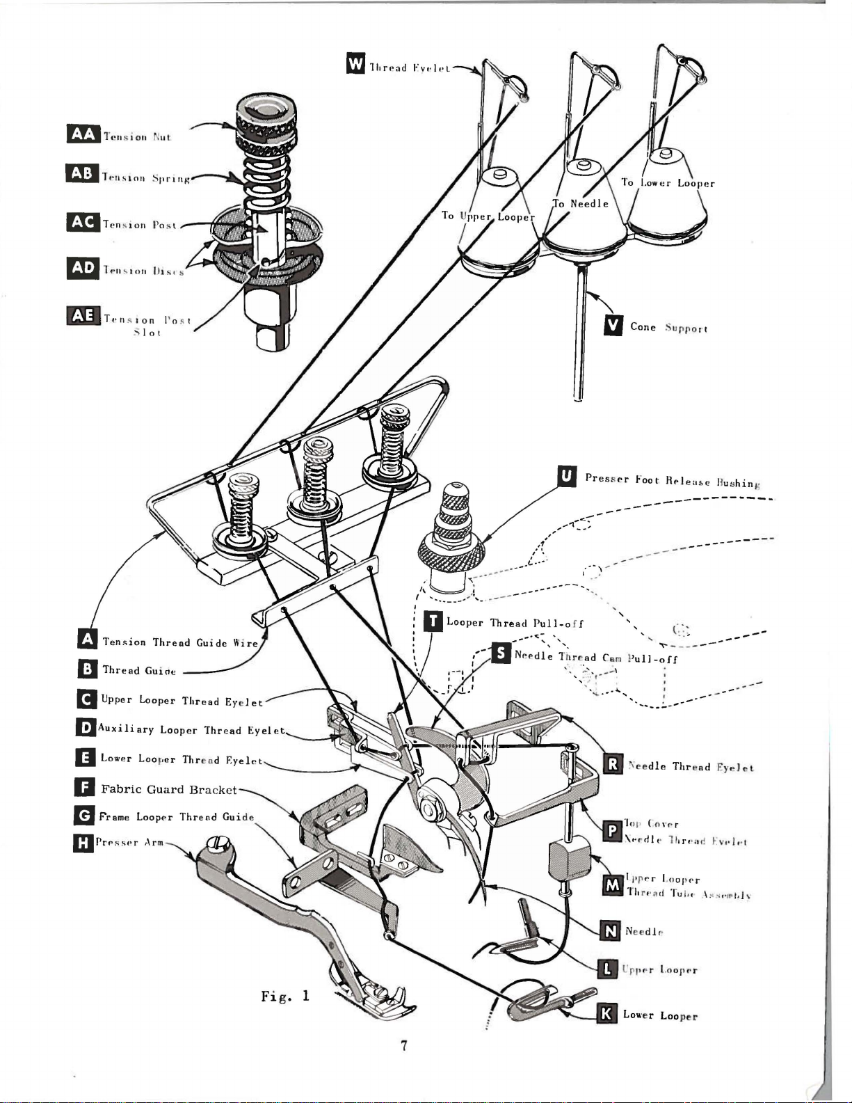
TO
THREAD
LOWER
LOOPER
Double end
e
yel
et
t
hread
of
frame
heel
of
from
are
left
in
Turn
thread
through
thread
looper
and
down
push
tube
CAUTION!
passing
Turn
highest
needle
hole
in
(E, Fig.
pull-off
looper
lower
left
to
hand.
looper
right.
handwheel
through
both
eyes
must
pass
thread
through
down,
from
handwheel
position.
thread
top
cover
of
thread
1)
from
(T).
thread
auxiliary
in
tube
thread
then
Be
tube
Insert
eyelet
needle
and
right
Lead
thread
guide
(K)
is
Left
eye
TO
until
of
upper
front
of
assembly
tube
insert
sure
upper
assembly
TO
in
operating
needle
(R),
thread
lead
to
left.
behind
(G).
all
the
of
lower
THREAD
point
of
looper
looper
looper
(M),
assembly
thread
looper
to
upper
THREAD
thread
under
eyelet
it
through
Note:thread
fabric
Turn
way
to
looper
UPPER
upper
thread
thread
thread
lead
through
thread
looper
THE
direction
from
neck
of
(P).
both
guard
handwheel
the
left;
can
LOOPER
looper
eyelet
eyelet
pull-off
thread
(M).
under
Pull
upper
is
eye.
NEEDLE
until
right
top
cover
Thread
eyes
must
in
then
be
threaded
(L)
(D)
(C)
(T).
looper
under
needle
to
casting;
of
pass
(F)
and
operating
thread
is
all
from
from
After
neck
thread
eye
lower
(N,
left,
needle
lower
in
front
through
through
easily
the
way
back
left
to
pulling
of
top
out
bottom
from
looper
Fig.
through
then
from
looper
of
both
direction
both
if
tweezers
left.
to
front,
right.
up
cover
of
front
to
thread
1)
is
both
eyes
down
through
front.
thread
looper
holes
until
eyes
Lead
then
Note;
upper
casting
tube;
back.
when
at
its
of
The
knurled
to
secure
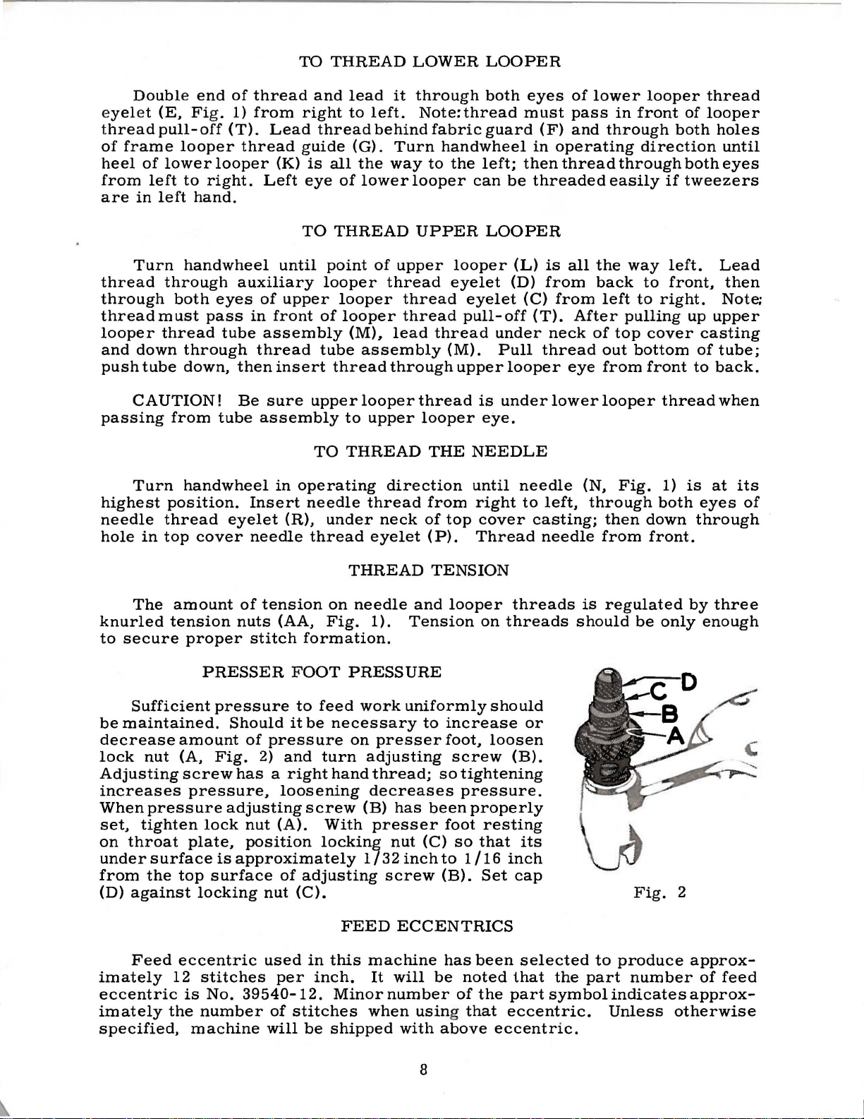
Sufficient
be
maintained.
decrease
lock
nut
Adjusting
increases
When
set,
on
under
from
(D)
pressure
tighten
throat
surface
the
against
Feed
imately
eccentric
imately
specified,
amount
tension
proper
PRESSER
pressure
amount
(A,
Fig.
screw
pressure,
lock
plate,
is
top
surface
locking
eccentric
12
stitches
is
No.
the
number
machine
of
tension
nuts
(AA,
stitch
formation.
FOOT
to
Should
of
it
be
pressure
2)
and
has a right
loosening
adjusting
nut
screw
(A).
position
approximately
of
adjusting
nut
(C).
used
per
in
inch.
39540-12.
of
stitches
will
be
THREAD
on
needle
Fig.
PRESSURE
feed
work
necessary
on
turn
adjusting
hand
decreases
(B)
With
locking
1/32
FEED
this
machine
It
Minor
when
shipped
TENSION
and
1).
Tension
uniformly
to
increase
presser
thread;
has
presser
nut
screw
been
(C)
inch
foot,
so
foot
to
(B).
ECCENTRICS
has
will
be
number
using that
with
above
looper
on
should
loosen
screw
tightening
pressure.
properly
resting
so
that
1/16
Set
been
noted
of
the
eccentric.
threads
threads
or
(B).
its
inch
cap
selected
that
the
part
symbol
eccentric.
is
regulated
should
to
produce
part
indicates
Unless
be
only
Fig.
2
number
otherwise
by
three
enough
approx-
of
feed
approx-
8
FEED
ECCENTRICS
(Continued)
Following
5, 6,
36,
trics
a
11
7,
40.
may
minor
39540-8
Before
guard.
upper
suggested
Fig.
stitch
8,
9, 10,
Only
one
be
ordered
number
11
•
assembling
knife
sequence.
3
number
11,
12, 13, 14,
eccentric
separately.
suffixed
to
ASSEMBLING
sewing
assembly,
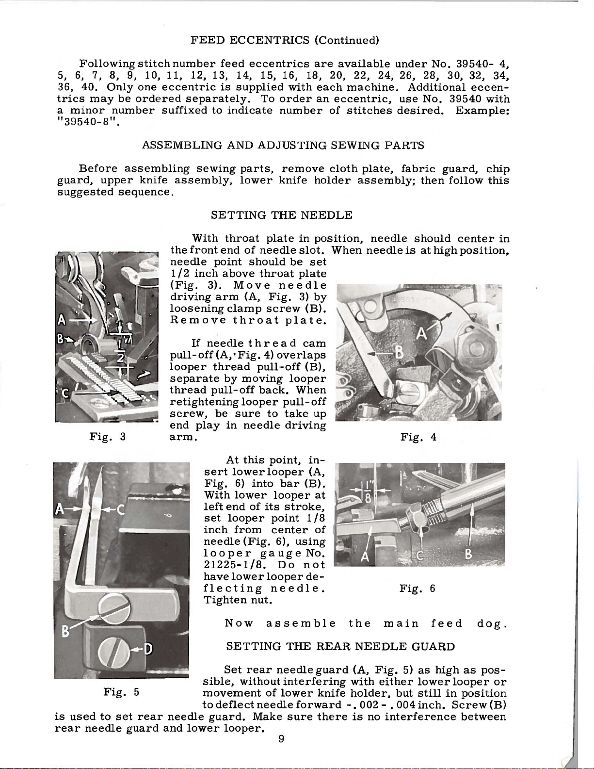
SETTING
With
the
front
needle
1/2
(Fig.
point
inch
3).
driving
loosening
Remove
If
needle
pull-off(A,•Fig.
looper
thread
separate
thread
pull-off
retightening
·
screw,
end
be
play
arm.
feed
is
supplied
indicate
AND
parts,
lower
throat
end
above
Move
arm
clamp
throat
by
sure
in
eccentrics
15,
16, 18,
with
To
order
number
ADJUSTING
remove
knife
THE
plate
of
needle
should
throat
needle
(A,
Fig.
screw
plate.
t h r e a d
4)
overlaps
pull-off
moving
looper
back.
looper
needle
pull-off
to
take
driving
are
each
an
holder
NEEDLE
in
position,
slot.
be
set
plate
3)
by
(B).
cam
(B),
When
up
available
20,
22.
machine.
eccentric,
of
stitches
SEWING
cloth
plate,
assembly;
When
needle
under
24,
use
desired.
PARTS
needle
No.
26,
28,
Additional
No.
fabric
then
should
is
at
high
Fig.
4
39540-
30.
32,
eccen-
39540
Example:
guard,
follow
center
position,
4,
34,
with
chip
this
in
is
rear
used
needle
Fig.
to
set
guard
5
rear
needle
and
lower
At
this
sert
lower
Fig.
With
left
set
inch
needle
6)
lower
end
of
looper
from
(Fig.
looper
21225-1/8.
have
lower
flecting
Tighten
Now
SETTING
Set
rear
sible,
without
movement
to
deflect
guard.
looper.
point,
looper
into
looper
its
point
center
6),
gauge
Do
looper
needle.
nut.
assemble
needle
of
needle
Make
in(A,
bar
(B).
at
stroke,
1/8
of
using
No.
not
de-
THE
REAR
guard
interfering
lower
knife
forward
sure the
9
the
NEEDLE
(A,
with
holder,
-.
re
is
main
Fig.
either
002 - .
no
interference
Fig.
GUARD
5)
as
lower
but
still
004
inch.
6
feed
high
in
dog.
as
looper
position
Screw
between
pos-
or
(B)