

Page 1
®
INDUSTRIAL
SEWING
FINEST QUALITY
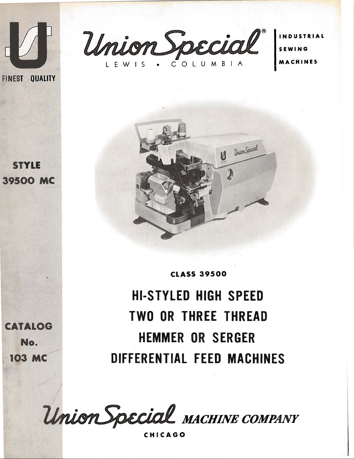
STYLE
39500
MC
LEWIS
•
COLUMBIA
MACHINES
•
CATALOG
No.
CLASS
HI-STYLED
TWO
OR
HEMMER
DIFFERENTIAL
CHICAGO
HIGH
THREE
OR
FEED
39500
SPEED
THREAD
SERGER
MACHINES
Page 2

Page 3
(Supplement
Catalog
to
Catalog
INSTRUCTIONS
FOR
No.
103
MC
No.
103
FA)
ADJUSTING
LIST
First
AND
OF
CLASS
Style
39500
OPERATING
PARTS
39500
MC
Edition
Union
Rights
Copyright
By
Special
Reserved
1969
Machine
in
All
Countries
MACHINE COMPANY
INDUSTRIAL
Printed
August,
1969
SEWING
CHICAGO
in
3
MACHINES
U.S.
A.
Co.
Page 4
IDENTIFICATION
OF
MACHINES
the
Each
machine.
Union
numbers
Example:
only
minor
dard
Style
Styles
which
3
95
junction
FA
differs
00".
This
are
catalog
therewith.
illustrated
illustration
and
the
number
numbers
ference
ber
listed
This
in.
Class
given
of
handwheel
numbers
It
can
39500.
from
only,
catalog
Special
Style
have
"Style
changes
number.
of
machines
from
will
and
in
the
also
References
the
operator's
is
machine
numbers
one
or
more
39500
are
MC".
made
Example:
similar
the
Style
is a
supplement
Only
and
listed
be
found a listing
of
pieces
merely
should
second
applies
be
away
never
column.
specifically
applied
from
is
identified
are
classified
letters
Special
in a standard
"Style
in
construction
number
APPLICATION
to
those
parts
at
the
of
required.
indicate
be
with
to
directions,
position
the
used
discretion
while
operator.
suffixed,
Style
39500
in
that
Catalog
used
back
the
of
parts,
Numbers
position
in
ordering
to
the
such
seated
by a Style
as
standard
but
numbers
machine~
MCZ".
are
grouped
it
contains
OF
CATALOG
No.
103
on
Style
this
39500
catalog.
with
in
of
that
their
the
parts.
standard
to
as
some
right,
at
the
Style
number
and
never
contain
a
"Z"
no
letters.
FA
and
MC,
On
part
first
part
Always
of
Special
left~
machine.
on a name
special.
contain
the
is
suffixed
the
letter
Standard
"Z".
to
under a Class
Example:
should
but
the
numbers~
column
in
the illustration.
machine
Styles
front~
be
not
page
use
as
of
back,
used
on
opposite
are
the
listed
machines
Operatin
plate
Style
letter
"Z".
When
the
stan-
number,
"Class
in
con-
Style
39500
the
description
reference
Re-
part
num-
here-
etc.,
g di
are
rection
on
in
Hi-Styled
Thread
Trimming
System.
39500
MC
thread
cotton~
505
inch.
Maximum
CAUTION!
filled
before
straight
should
be
Machine
sight
gauge
gauge
lines
Machine
main
reservoir
High
and
Two
Mechanism
Light
blind
flat
EFd-1.
Stitch
beginning
mineral
used.
is
on
when
is
Speed,
Looper
Single
Three
with
to
medium
hemming
and
ribbed
Standard
range 8 to
recommended
Oil
was
drained
to
oil
of a Saybolt
filled
front
with
of
machine.
machine
automatically
filled.
Check
STYLE
Curved
Thread
Spring
duty~
or
serging
knit
seam
30
per
speed 7 000
from
operate.
viscosity
oil
at
spring cap
Red
is
stationary.
lubricated.
oil
daily
OF
Blade
Pressed
two
way
small
materials.
width
for
inch.
OILING
machine
Oil
bulb
before
MACHINE
Needle~
Over
seaming
Lower
combination
diameter
hemming
Cam
R.
P.M.
capacity
of
2 00
in
on
oil
No
oil
the
One
Knife,
Seam
specifications
1 I 8
adjusted
when
top
shipped~
of
Class
to
250
cover.
level
ing
is
morning
Looper-One
Machine.
Automatic
machine,
light
weight
inch
main
and
39500
seconds
Oil
indicator
necessary,
start;
Differential
for
rayon~
503
and
for
different
so
reservoir
is
si?E,
at
100
level
should
other
add
oil
Spreader
Lubricatin
two
or
s
ilk,
EFc-1~
sergin
ial
must
ounces.
Fahrenheit
is
checked
show
between
than
keepin
as
required.
Two
Feed~
g
three
wool~
or
g 3 I
16
feeds.
be
A
at
g
The
oil
It
is a magnetic
have
entered
drain
the
plug
screw
crank
screw
designed
case.
is
located
It
to
accumulate
should
at
back
be
4
of
machine
possible
removed
foreign
and
near
cleaned
bottom edge
materials
periodically.
of
which
base.
may
Page 5
NEEDLES
Each
denotes
number,
in
thousandths
size
number
packaged
Class
needle
for
available
Type
154
sample
on
No.
GAS
To
label.
have
needle,
Selection
should
pass
Success
of
needles
reputation
more
than
Union
the
kind
Special
of
stamped
of
represent
and
sold
39500
machines
Style
of
the
recommended
Round
struck
025, 027,
needle
or
A
complete
of
proper
freely
in
the
packaged
for
producing
three-quarters
shank,
on
the
an
inch,
the
by
Union
39500
shank,
groove,
029,
orders
the
type
order
through
operation
under
needle
has
point,
needle
shank,
midway
complete
Special.
use a curved
MC
is
Type
needle.
round
point,
spotted,
032, 036,
promptly
and
size
would
needle
size
needle
of
Union
our
brand
highest
of a century.
both
type
length,
groove,
denotes
between
symbol
blade
154
GAS.
Description
curved
chromium
040, 044, 049,
and
number
read:
is
determined
eye
in
Special
name,
quality
needles
and
largest
shank
which
needle.
Below
blade,
plated
accurately
should
"1
000
Needles,
order
to
machines
~
size
finish
number.
and
other
diameter
and
is
and
eye.
given
The
is
Sizes
Collectively,
on
the
standard
the
description
standard
and
is
available
054.
filled,
be
forwarded.
Type
by
size
of
produce a good
can
be
.
in
materials
The
details.
of
blade,
label
length,
an
empty
Use
154
GAS,
thread
stitch
secured
which
and
workmanship
type
number
The
measured
type
of
all
needles
recommended
and
sizes
single
in
groove,
sizes
package,
description
Size
used.
027".
Thread
formation.
only
by
is
backed
by
size
and
022,
a
use
a
for
Release
Fig. 1 or
direction
No.
21388AU,
Again
left,
To
insert
turn
replace
position,
nut.
Return
(AG).
After
up
through
thread
thread
back,
is
threaded
eyelet.
are
and
through
to
front.
post
slot
pressure
1A)
and
until
handwheel
needle
turn
presser
thread
the
threaded
then
through
the
middle
All
(K)
swing
needle
is
furnished
needle,
in
handwheel
comes
back
hole
Next,
through
through
the
hole
threads
in
tension
on
presser
presser
at
its
until
leave
holder
until
arm
from
of
the
the
lower
upper
from
then
post
CHANGING
arm
lowest
with
machine,
needle
needle
until
holder
(U)
to
cones
thread
upper
the
upper
hole
front
continue
(G)
foot
by
(U)
out
point
is
at
high
holder
it
rests
is
position
THREAD
on
cone
eyelet
looper
hole
hole,
of
to
from
the
back
between
and
on
NEEDLES
turning
of
position.
of
travel.
loosen
position;
at
high
against
again
and
at
re-lock
STAND
support
(B),
thread
of
tension
back
tension
and
then
the
through
presser
needle
position
stop
its
low
(A,
then
(505
to
front.
thread
through
tension
eyelets
foot
Turnhandwheel
Using
hexagonal
clamp
withdraw
and,
pin.
point
Keeping
of
presser
Fig.
down
1
through
STITCH
thread
guide
The
guide
(C)
the
discs
in
front
release
nut
needle.
with
travel;
foot
release
or
1A)
the
only)
(C)from
lower
from
lower
(J),
through
thread
bushing
in
socket
about
the
needle
then
it
front
and
looper
back
hole
operating
wrench
1/4
turn.
flat
to
in
tighten
bushing
is
brought
hole
the
needle
front
thread
to
front,
from
back
tension
guide
(AG,
the
this
of
to
(M).
NOTE:
Refer
to
Fig.
1
for
threading
503
stitch
stitch.
5
or
Fig.
1A
for
threading
505
Page 6
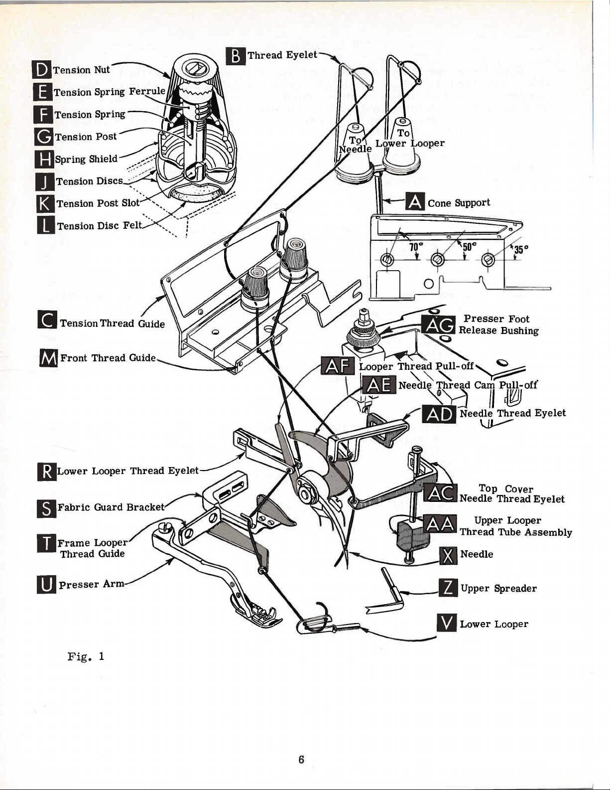
li]
Tension Nut
~~
Tension
II
Tension Spring
[!]
Tension
IIJ
spring
Spring
Post
Shield _
Fer~
---,~/
nlh~l\d:\\
~~
Thread
Eyelet
O Tension
P!.ll
Tension
..
II
Tension
f1J
Front
I:J
Lower
Discs
Post
Disc
Thread
Looper
< .
Slot .
••.
Felt
Thread
'......
. ..
--~;:::.:"
·-~"">"
. j
~~~
Presser
Release
0
Foot
Bushing
BJ
D)
Fabric
Presser
Fig.
Guard
1
6
......
Top
Needle
Upper
Thread
Cover
Thread
Looper
Tube
Assembly
Eyelet
Page 7

li]
Tension Nut
(I
Ten
IJ
Tension
[!]
Tension
IIJ
spring
sio
n Spring
Fer
~
Spring~
Post
Shield
r..-~:=-h'\.1
g Tension
~~Te
II
[i
f1J
~~~
I:J
nsion
Tension
Tension
Front
Upper
Lower
Discs
Post
Disc
Thread
Thread
Looper
Looper
-<:
.
Slot ·.
Felt
Guide
Guide
Thread
Thread
Cone Support
·.
Eyelet
Eyelet
Frame
D
Thread
m
Presser
Looper
Guide
Arm
7
M~:.
Top
Needle
Thread
Upper
Lower
Thread
Upper
Tube
Looper
Looper
Cover
Eyelet
Looper
Assembly
Page 8

Only
Parts
It
are
will
quence
The
recommended
looper
parts
placed
simplify
of
threading
second
involved
in
their
the
the
sequence
and
the
in
threading
relative
threading
lower
needle
of
looper
of
threading
third.
THREADING
are
shown
positions
these
first
for
machines
and
the
in
clarity.
the
505
threading
to
follow
needle
stitch
is
diagram
the
second
lower
(Fig. 1 and
recommended
for
the
503
looper
first~
1A).
se-
stitch.
upper
Before
ting
direction
foot
by
position.
Be
tween
posts
for
tension
should
the
Double
(M,
Fig. 1 or
let
(R~
thread
thread
(V)
is
all
eye
of
Double
Fig.
to
the
1A).
left.
front,
NOTE:
beginning
turning
sure
the
be
different
end
Fig. 1 or
pull-off
guide
lower
the
{T).
way
looper
end
Turn
Lead
then
through
Thread
until
needle
presser
threads,
discs
(J)
positioned
threads
of
thread
1A).
1A)
(AF).
Turn
to
TO
of
thread
handwheel
thread
must
to
thread,
foot
as
and
as
TO
and
Then
lead
from
Lead
handwheel
the
left,
can
be
THREAD
and
through
both
eyes
pass
swing
(X)
is
at
release
they
in
tension
so
the
indicated
THREAD
lead
thread
right
to
thread
then
threaded
THE
lead
until
of
in
front
cloth
high
bushing
come
post
tension
in
THE
it
through
through
left.
behind
in
operating
thread
easily
UPPER
it
through
point
auxiliary
upper
of
looper
plate
position.
(AG)
from
the
slots
post
Fig. 1 and
LOWER
the
both
NOTE:
fabric
through
if
tweezers
LOOPER
the
of
upper
looper
looper
thread
open
Now
and
tension
(K)
in
slot
will
1A.
LOOPER
right
eyes
thread
guard
direction
both
left
eyelet
looper
thread
thread
pull-off
and
turn
release
swing
thread
tension
be
at
eyelet
of
lower
must
(S)
and
until
eyes
are
(505
of
(W~
eyelet
handwheel
pressure
presser
guide
posts
the
approximate
of
front
looper
pass
through
heel
from
in
left
left
STITCH
front
Fig.
1A)
eyelet
{N)
from
(AF).
arm
(G).
in
front
of
to
hand.
ONLY)
thread
(P)
in
on
(U)
(C)~
The
thread
thread
of
frame
lower
right.
guide
is
all
from
left
to
opera-
presser
out
are
be-
tension
angle
guide
eye-
looper
looper
looper
Left
(M~
the
way
back
right.
of
to
After
of
top
bottom
looper
Double
(M,
at
its
needle
in
top
The
nuts
stitch
pulling
cover
of
tube;
from
front
end
Fig. 1 or
highest
thread
cover
needle
amount
(D,
Fig. 1 or
formation.
up
casting
push
to
needle
1A).
position.
eyelet
thread
of
tension
lA).
upper
and
tube
back.
thread
Then
Insert
(AD),
looper
down
through
down
TO
and
turn
needle
under
eyelet
on
the
Tension
thread
tube
thread
and
then
THREAD
lead
it
handwheel
thread
neck
of
(AC).
THREAD
needle
on
and
threads
assembly
tube
insert
THE
NEEDLE
through
in
operating
from
top
cover
Thread
TENSION
looper
should
8
assembly
thread
middle
right
casting;
needle
threads
be
(AA),
throu
eyelet
direction
to
left,
from
is
only
enough
lead
thread
(AA).
gh
of
front
until
through
then
down
front.
regulated
Pull
the
eye
thread guide
needle
both eyes
throu
to
secure
under
thread
of
gh
by
tension
proper
neck
out
upper
(X)
is
of
hole
Page 9

PRESSER
FOOT
PRESSURE
Sufficient
should
or
loosen
Adjusting
creases
pressure
lock
position
be
maintained.
decrease
lock
screw
pressure.
adjusting
nut
(A).
locking
proximately
adjusting
Feed
screw
eccentrics
approximately
feed
eccentric
39540
of
chine
B-8.
stitches
will
obtainable
be
Generally
of
stitches
and
direction
produced;
presser
the
nut
(A.
has a right
With
nut
1 I 32
(B).
14
is
Minor
shipped
speaking,
of
stretch
foot
amount
Fig.
loosening
screw
presser
(C)
inch
to
Set
used
stitches
No.
39540
numbers
when
with
main
pressure
Should
2)
of
and
it
pressure
hand
decreases
(B)
has
foot
so
that
1 I
16
inch
cap
(D)
FEED
in
Style
per
inch.
B-14.
of
the
using
above
differential
(left
hand)
of
material
to
feed
be
necessary
on
turn
adjusting
thread.
so
pressure.
been
properly
resting
its
under
from
the
against
ECCENTRICS
39500
while
that
MC
It
will
that
part
eccentric.
symbol
combination
(right
feed
eccentric
being
work
to
presser
screw
tightening
set.
on
throat
surface
top
locking
machines
be
noted
of
the
of
hand)
sewn.
uniformly
increase
foot~
(B).
in-
When
tighten
plate.
is
ap-
surface
nut
of
(C).
have
that
the
differential
indicate
Unless
eccentrics.
feed
eccentric
is
selected
or
type
of
been
part
selected
number
feed
eccentric
approximately
otherwise
specified.
determines
in
relation
operation.
Fig.
to
of
the
2
produce
the
main
is
number
number
to
degree
No.
ma-
Following
-6.-7.
-36,-40.
may
be
number
-8.
-9.
Only
ordered
suffixed
stitch
-10. -11.
two
eccentrics
separately.
to
indicate
number
-12,-13.
feed
eccentrics
-14. -15.
are
supplied
To
order
number
of
ASSEMBLING
Before
remove
knife
ming
cloth
assembly~
guide
quence.
With
should
needle
112
or
driving
(B).
is
inch
set
Remove
center
the
arm
properly
-16.
-18,-20.
with
an
eccentric.
stitches
assembling
plate.
assembly;
SETTING
throat
in
at
high
above
height
(A,
throat
and
are
available
each
AND
lower
plate
the
position.
throat
above
Fig.
clamp
-22. -24.
machine.
use
desired.
ADJUSTING
and
fabric
knife
then
THE
assembled
front
end
needle
plate
(Fig.
throat
3)
by
plate.
screw
under
No.
-26. -28.
39540
-30.
Additional
No.
39540 B with a minor
Example:
"39540
SEWING
adjusting
guard,
holder
follow
this
sewing parts.
chip
guard,
assembly.
suggested
NEEDLE
in
position.
of
3).
plate.
loosening
after
(B)
needle
has
needle
point
should
To
mov
clamp
has
been
slot.
ali
B-4.
-5.
-32. -34.
eccentrics
B-8".
PAR
TS
upper
hem-
se-
ne
edle
When
be
set
gn ne
e ne
edle
edle
screw
been
set
tightened.
At
this
Fi
g. 3
bar
(B).
set
looper
using
looper
ble
differential
point.
With
point
looper
gauge
deflecting
9
insert
lower
3 I 32
No.
needle.
(front)
looper
inch
2122
feed
lower
at
from
5-3 I 32.
Tighten
dog.
looper
left
center
nut
(A~
end
of
Do
(C).
Fig.
of
its
needle
not
have
Now
4)
into
stroke~
(Fig.
4)
lower
assem-
Page 10

looper
u?til
moves
the
Fig.
needle
4
to
the
springs
right,
forward
its
possible,
looper
in
position
inch.
Make
needle
point
from
SETTING
Set
rear
or
Screw
sure
guard
Now
finish
should
rear
THE
needle
without
movement
to
deflect
(B)
there
and
SETTING
lower
be
set
guard
surface
REAR
guard
interfering
of
lower
needle
is
used
is
no
lower
THE
looper
into
the
NEEDLE
(A,
Fig.
with
knife
forward
to
set
rear
interference
looper.
LOWER
needle
another
LOOPER
adjustment.
scarf
GUARD
5)
as
high
either
holder,
needle
between
. 002 - • 004
but
• 002 - • 004
As
(A.
Fig.
as
lower
still
guard.
rear
lower
6)
inch.
Assemble
looper
guard
(D)
is
setting.
guard
Fig.
the
right
position
end
of
upper
SETTING
is
springing
as
close
used
to
make
and
differential
SETTING
6
end
the
upper
the
upper
looper
or
front
as
possible
adjust
sure
THE
of
its
looper
spreader
THE
FRONT
needle
needle
and
set
there
feed
UPPER
Insert
upper
(B)
holds
in
its
looper
out.
or
upper
shaft,
(C.
Fig.
looper
and
allows
justed
Preliminary
stroke,
looper
or
guard
off
back
to
needle
front
is
no
dog.
LOOPER
spreader
the
holder.
or
turned
looper
if
not
7)
or
spreader
laterally.
the
or
spreader
spreader
holder
NEEDLE
(C.
Fig.
guard.
without
needle
interference
OR
upper
spreader
on
upper
and
around
or
already
clamp
holder
Setting:
upper
shank
(Fig.
looper
in
spreader
holder
to
looper
shank
7).
GUARD
5).
When
set
front
touching.
guard.
between
SPREADER
(A.
its
holder.
looper
permits
to
collar
be
be
pushed
its
shank.
in
place.
rotated
When
or
slightly
should
or
holder
holds
in
needle
Screw
After
needle
Fig.
Screw
spreader
the
Insert
Screw
the
or
the
upper
spreader
back
extend
lower
this
7)
or
upper
in
or
into
upper
shaft,
ad-
of
1 I 32
looper
holder
vertical
to
or
1 I
Fig.
spreader
should
(Fi
16
inch
5
be
g.
above
7).
is
set
at
to
Top
the
As
the
Fig.
7
upper
the
point
should
approximately
or
spreader
Turn
at
the
upper
extend
and
also
If
resetting
spreader
of
pass
the
left
end
looper
about
be
holder
15
looper
the
upper
just
behind
• 002
and
the
handwheel
of
its
or
the
5132
inch
I 32
inch
is
necessary.
(A,
or
looper
inch
lower
until
travel.
lower
to
the
above
Fig.
spreader
or
the
eye
clearance
looper
the
At
point
left
the
do
it
9).
10
the
upper
this
of
of
top
by
moves
Vee
of
the
between
(Fig.
looper
position.
the
upper
the
centerline
of
the
moving
from
notch
lower
8).
throat
the
right
of
the
looper.
the
upper
or
spreader
the
point
spreader
of
plate
upper
to
spreader
looper
of
should
the
needle
(Fig.
looper
left.
with
is
the
9).
or
Page 11

SETTING
THE
UPPER
LOOPER
OR
SPREADER
(Continued)
Fig.
SETTING
Now
feed
chaining
all
1 0)
teeth
plane.
by
with a straight
assemble
dogs
with
rotating
bar.
dog
feed
so
the
all
sighting
should
throat
8
THE
assemble
(B,
feed
dogs
top
lie
This
across
throat
now
plate
feed
FEED
main
Fig.
dog
(C).
(A,
B,
surfaces
in
the
can
be
the
edge.
plate.
be
surface
tilting
Now
ference
spreader
downstroke.
upper
looper
slightly
tance
left
end
justments,
reduce
looper
set
to
and
9.
DOGS
(back)
10)
and
Set
C,
Fig.
of
the
same
checked
teeth
Now
Feed
leveled
by
adjusting
check
between
and
looper
or
and
counterclockwise,
of
the
clearance
or
spreader
maintain
pin
setting
the
the
If
needle
or
spreader,
spreader
rotate
machine.
in
opposite
dimension
(D).
This
needle
looper a short
and
to
avoid
upper
on
rubs
out
These
between
the
pin
the
pull
of
looking
movement,
needle.
of
raises
inter-
looper
the
needle
back
the
upper
its
holder
same
the
upper
Figs.
Fig.
or
or
of
dis-
from
ad-
will
Re-
8
10
lowers
the
Fig.
back
9
end
of
feed
The
teeth
feed
and
throat
surface
ing
(A,
sleeve
bracket
and
manually
(D)
throat
hexagonal
Lower
So
trim
tightening
first
tilting
differential
plate,
Replace
the
lower
Fig.
(B)
holder
should
plate
knife
no
lateral
is
changed
Lower
feed
dogs
appear
adjusting
and
of
throat
SETTING
lower
knife
11)
so
seats
(C) a free
assembly
pressed
be
set
surface.
head
is
spring
adjustment
knife
screw
should
above
pin
feed
chaining
plate.
THE
knife
holder
that
when
against
lateral
is
at
its
with
screw
may
be
(E)
be
set
throat
in
dog
holder
obtained
upper
the
Adjustments
which
pressed
is
secured
against
plate.
place.
teeth
feed
LOWER
assembly.
assembly,
the
face
the
throat
motion
corner.
cutting
necessary
level
Screw
Now
3/64
dog
teeth
KNIFE
of
plate
of
the
when
edge
are
holds
against
in
any
knife
at
the
set
inch
flush
In
tighten
the
lower
the
Lower
flush
made
lower
upper
when
position
holder
time
(E)
locks
the
main
above
with
replac-
screw
flange
mounting
knife
knife
knife
with
with
knife.
knife.
width
shaft.
the
the
on
is
the
of
by
Fig.
11
11
Page 12

knife
Set
to
the
desired
the
needle~
SETTING
width
lock
of
the
THE
trim
lower
LOWER
by
measuring
knife
holder
KNIFE
from
shaft
(Continued)
the
right
with
screw
edge
(E).
of
the
lower
Replace
ting
nut
bottom
1/64
inch
against
After
tightened
when
upper
Length
feed
eccentrics
actuates
eccentric
In
assembling feed
ing
each
Tighten
To
(D)
from
direction
Using
tries
back
hooked
as
and
upperknifeassembly.
(G)
to
of
its
below
the
upper
upper
to
lock
knife
SETTING
of
main
(B)
other.
nut
(C)
change
end
until
shown
forth
hold
stroke~
clamp
front
cutting
knife
knife
upper
is
and
has
knife
replaced.
THE
stitch
(rear)
used.
is
determined
Outer
feed
actuates
eccentrics,
Be
careful
securely.
feed
eccentrics,
of
shaft
key
(E).
slot
eccentric
and
withdraw
slightly
during
SETTING
(H)
in
cutting
edge
of
slightly
been
holding
STITCH
(left)
dog,
the
differential
not
remove
Turn
in
eccentric
extractor
eccentrics.
extraction.
THE
Clamp
its
most
edge
lower
knife.
back
set
for
block
LENGTH
by
the
eccentric
while
the
(front)
be
sure
to
damage
nut
handwheel
is
toward
(F)~
supplied
UPPER
upperknife
clockwise
of
upper
The
from
proper
(K)
the
width
in
place.
combination
(A,
Fig.
inner
feed
hubs
are
shaft
(C)
in
or
and
operating
the
with
It
may
KNIFE
(F~
Fig.
position
knife
cutting
chain
of
should
guard
edge.
trim~
This
of
12)
(right)
dog •
fac-
key
.
washer
front.
machine~
be
necessary
11)
against
extend
should
screw
will
simplify
Fig.
reach
to
in
position,
upper
not
be
(J)
12
behind
move
set-
knife.
less
set
should
At
than
down
be
resetting
eccen-
handwheel
If
eccentrics
and
washer
connection
clamp
screw
required.
The
foot
sure
the
presser
unlocked.
are
(D)
from
(H).
Then
Fig.
(G)
13
and
Retighten
lifter
arm
unusually
shaft
continue
then
collar
lever
arm
does
tight
(E)~
it
as
shift
the
screws
(A,
not
bind
fitting,
may
be
helpful
originally
Assemble
With
into
align
throat
needle
sewing position
needle
plate.
presser
needle
that
throat
hole
the
plate.
realigned
foot
lifter
shaft,
and
Fig.
foot
clamp
and
loosen
lifter
14)
rise
in
addition
to
suggested.
SETTING
the
in
high
holes
The
foot
must
in
throat
bottom
If
with
throat
lever
collar
lever
screw.
and
the
when
to
removing
remove
THE
presser
nut
PRESSER
foot
position,
and
set
(front
front
be
of
the
necessary~
shaft
and
edge
aligned
plate.
presser
plate
(H,
Fig.
It
presser
slots
screws
shaft
collar
presser
to
(B) s
foot
the
ecure
nut
(G)
and
to
swing
the
presser
back)
of
with
is
foot
14).
(B~
left
release
(
C~
feed
FOOT
presser
presser
and
needle
front
also
be
flat
foot
by
shifting
To
Fig.
or
the
bushing
Fig.
13)
driving
arm.
arm
foot
to
flat
on
hole
edge
in
of
important
on
the
can
be
the
move
shaft.
14)
right
the
and
as
Be
is
12
Page 13

SETTING
THE
PRESSER
FOOT
(Continued)
NOTE:
1A.
With
and
in
the
Operate
moves
While
of
needle
increase
1A)
farther
thread
off
thread
thread
Fig.
Be
middle
machine
tongue
sewing
to
the
14
sure
machine
tensions
of
its
slowly
freely.
NEEDLE
on
material.
required
drawn
rear.
light.
front
for
on
the
presser
upper
the
inch
presser
should
nut
guard
turnhandwheel
es
is
threaded
set
lower
to
back
with
location.
presser
THREAD
check
the
stitch
downstroke.
Adjust
lifter
foot
looper
nut
(D).
free
motion
foot
be
made
(F).
Re-assemble
and
cloth
its
highest
STARTING
according
looper
foot
in
CONTROL
needle
should
thread
be
position
lever
can
be
raised
or
spreader
There
begins
of
with
should
foot
to
screw
the
plate.
until
To
upper
position.
TO
OPERATE
to
threading
thread
place;
eyelet
make
(505 STITCH)
control
drawn
needle
on
thread
stop
no
will
be
lifter
rise.
(E)
chip
assemble
knife
diagram
(R)
sure
as
follows:
needle
screw
(C)
higher
permit;
from
lever
This
and
locked
1/16
before
adjustment
guard.
chip
assembly
Fig. 1 or
about
chain
horizontal
forms
About
downstroke.
eyelet
(AD.
so
than
then
to
fabric
guard.
reach-
that
the
lock
1/8
the
with
and
60%
To
Fig
•
Set
ward
in
Frame
inch
its
right
stroke.
With
to
rest
thread
Position
upper
To
lower
While
needle
should
slightly
stroke.
(AE)
just
needle
lower
its
slot.
looper
of
material
on
top
is a little
looper
reduce
looper
sewing
thread
be
just
if
excessive
position
contacts
thread
LOWER
looper
LOOPER
thread
thread
lower
looper
UPPER
under
of
lowerlooperthread
slack
presser
when
POSITIONING
of
lower
thread
amount
thread
looper
tensions.
of
lower
tension.
NEEDLE
on
material.
is
drawn
tight
on
enough
thread
needle
needle
eyelet
thread
thread.
(AD, Fig. 1)
eyelet
guide
(V)
(T)
heel
LOOPER
upper
thread
thread
THREAD
check
needle
to
feed
is
pulled
eyelet
THREAD
(R. Fig. 1A)
should
be
eyelet.
THREAD
foot.
set
eyelet
looper
THE
at
the
in
upper
(R).
reaches
SQUARE
edge
the
CONTROL
needle
down
chain
To
farther
stroke.
off
on
the
(AD.
Fig.
increase
to
CONTROL
about
set
with
when
lower
CONTROL
looper
and
back
the
EDGE
is
located
stitch.
or
(503 STITCH)
thread
stitch
up
1) so
thread
the
At
top
tongue.
stroke.
rear.
control
that
drawn
(505 STITCH)
horizontal
its
eyelet
looper
and
is
(505 STITCH)
left
thread
far
end
eyelet
enough
of
(505 STITCH)
by
balancing
close
of
the
edge
as
follows:
needle
Stitch
With
needle
needle
thread
on
downstroke.
all
the
way
approximately
at
the
left
(N.
Fig.
so
upper
its
stroke.
needle and
more.
increa
Usually
stroke.
tends
to
at
cam
thread
pull
bottom
pull-off
position
for-
1/8
end
of
1A)
looper
se
all
down
of
13
Page 14

LOWER
LOOPER
THREAD
CONTROL
With
and
left
Frame
inch
left
Before
Moderate
SKIPPING:
1.
2.
3.
material
down
position.
to
the
end
of
Recheck
Recheck
Upper
Check
looper
far
enough
Lower
looper
right
its
proceeding.
change
Looper
clearance
or
of
travel.
in
For
occasional
lower
upper
spreader
under
thread
or
presser
so
thread
looper
heel
these
looper -needle
looper
Spreader".
between
thread
guide
eyelet
balance
tensions
SPECIAL
skipping.
or
needle
moves
foot.
is a little
(T)
of
THREAD
both
spreader
far
set
eyelet
should
looper
tensions
will
setting.
and
enough
lower
slack
(R)
be
(V)
TENSIONS
not
ADJUSTMENTS
check
-
lower
upper
left
looper
when
should
set
with
at
the
to
markedly
and/
or
See
"Setting
looper
looper
past
time
give a normal
adjust
needle.
thread
spreader
be
about
its
eyelet
lower
effect
the
as
the
crossing.
or
spreader.
eyelet
horizontal.
looper
outlined
Needle".
(R,
reaches
approximately
appearing
purl.
See
See
Fig.
its
is
at
below:
"Setting
that
1)
back
extreme
1 I 8
extreme
stitch.
the
upper
Setting 1 and 2 should
appearance
thread
to
bend
tension
CAUTION:
its
extreme
Make
Assemble
by
means
guide
the
slightly
stop
support
differences
amount
removing
the
Fig.
(D)
right
When
to
screw
bracket
Under
of
spring
15).
eyelet
in
looper
as
much
sure
the
of
screw
so
that
feed
slot
the
edge
the
right
(A,
normal
in
the
movement
lock
screw
and
pin,
Replace
that
skip
(R,
Fig.
thread
as
Looper
left
position,
SETTING
that
lock
hemming
(B.
the
left
in
the
guide
of
Fig.
16)
(E,
Fig.
conditions,
material
and
(B,
located
lock
is
definitely
1)
by
pull-off
possible
thread
THE
screw
guide
Fig.
parallel.
15).
side
throat
tip
is
located
15).
thickness.
the
Fig.
in
screw
be
made
lowering
(AF).
without
must.
or
HEMMING
(A,
of
plate.
in
the
pressure
16)
the
and
as
stitch
Fig.
support
With
its
tip
this
This
towards
edge
and
hinge
tighten
quite
not a needle
before,
will
bracket
the
is
position.
adjustment
guide
For
applied
adjusting
carefully.
it
slightly
After
distorting
appear
GUIDE
15)
is
knurled
even
the
block
with
front
is
example,
and
securely.
loop
and
this
stitch.
be
slightly
tight
SUPPORT
loose,
onto
the
adjusting
and
the
front
can
of
spring
to
the
the
edge
If
skip.
bringing
change,
slack
on
then
lower
parallel
or
be
the
hinge
loaded
as
in
edge
screw
guide
it
can
be
reposition
eyelet
increase
as
top
side.
BRACKET
proceed
knife
screw
to
leading
made
going
by
block
to
compensate
guide
which
support
over
tip
determined
lower
holes
looper
spreader
as
follows:
support
(C),
set
the
right
edge
positioning
and
edge
seams.
can
presses
bracket
looper
in
close
thread
reaches
bracket
the
side
should
guide
for
be
set
against
by
edge
of
be
the
the
The
by
(E,
14
Page 15

SETTING
THE
lock
against
HEMIVITNG
If
movement
screw
set
screw
pin
GUIDE
(B.
and
and
of
Fig.
lock
lock
SUPPORT
the
edge
16),
screw.
screw
guide
set
BRACKET
is
not
screw
Be
sure
is
tightened
required,
and
spring;
set
(Continued)
then
then
screw
against
is
set
remove
replace
tightened
screw.
the
thickness
screw
the
hinge
tween
tighten
and
adjust
so
that
the
center
screw
Fig.
(C,
the
screws
the
(F)
15
of
Fig.
block
edge
stop
tip
of
the
and
the
material
16)
(E)
guide
(C)
screw
of
the
edge
tighten
Adjust
adjusting
folded
point
re-tighten
Adjust
(F,
Fig.
between
edge
and
to
and
and
guide
holding
obtain
the
(D).
that
overhanging
guide
against
FINAL
the
screw
edge,
yet
the
15)
its
guiding
(D)
to
be
hemmed.
screw
the
proper
overhanging
Remove
is
in
front
guide
vertically.
stop
screw.
ADJUSTMENT
edge
guide
(C)
do
not
screw
so
show
(A,
(D,
that
overhanging
so
that
the
edge
and
corresponds
Loosen
(D),
now
distance
guide.
lock
of
lock
is
screw
screw,
located
Replace
OF
Fig.
the
on
Fig.
guide
space
the
with
set
move
be-
Re-
(F)
at
lock
HEMMING
15)
stitches
the
face
15)
securely.
by
of
GUIDE
turning
are
located
the
fabric.
Fig.
the
16
knurled
in
the
At
this
15
Page 16

16
,:l
~
I
,(..
~)~
.
~
?-
«
16
Page 17

The
parts
represent
illustrated
the
parts
that
on
are
pages
used
16
on
and
Style
18,
39500
and
described
MC,
but
not
on
used
this
on
page
Style
and
39500
page 19
FA.
Those
to
Use
this
parts
Styles
Catalog
catalog.
39500
Reference
descriptions.
Ref.
No.
1
Part
No.
39592
39592
39592
2
3
4
5
6
7
8
9
10
11
12
39520
39530
22738
22768
39530
39597
22738
39530
39505
39540 B-8
39540
13
14
15
16
17
39560
39508
39505
39526
39526
18
19
20
21
22
23
24
25
26
27
28
29
30
31
39505
39563
39556
22798
39556
605
39501
22657
39501
22513
39532
39582
39582
39582
shown
FA
No.
103
numbers
indicate
AE-4
AE-4
AE-4
AX
E
B
F
B
G
B-14
93 A
A
B
F
AY
AX
H
J
M
L
AS
D-12
K
D
AR
H
J
in
phantom
and
FA
that
they
views
MC.
(Style
are
39500
inside a bracket
are
component
Looper
Looper
Needle
Thread
Presser
Presser
Screw,
Screw.
Hinge
Stitch
Screw.
Chip
Chaining
Differential
Main
Screw,
Upper
Lower
Main
Feed
for
Spreader,
Looper----------------------------------
Feed
Differential
Differential
Chaining
Needle
Chain
Thread
Cutting
Screw,
Chain
Screw.
Cloth
for
Plate-------------------------------------
Screw.
Cloth
Screw.
Latch
Side
Cover-------------------------------------
Spring
Rivet
and
FA)
bearing
for
parts
all
on
no
reference
parts
the
not
picture
illustrated
of a complete
number
plates
and
part
are
or
described
have
or
assembly.
common
indented
Description
Thread
Thread
Foot---------
Spring
Tension
Tension
Tension
Foot
for
chain
for
stitch
Tongue,
for
chip
Spring.
Spring.
for
for
503
505
Spring--------------------
-
-------------------------
Chain
Shield-------------------
shield----------------------
tongue
---------------------
------------------------------marked
guard
"DV"
-----------------
-----------------------
stitch-----stitch------
Guard---------------------------------
Feed
Feed
Dog,
Feed
Driving
main
Dog,
Feed
Feed
Dog.
Cam
Knife
for
chain
Cutter
chain
for
cloth
Plate
for
Stud
latch
Spring
------------
marked
Driving
"S".
for
Eccentric---------------
Eccentric---------------------
feed
marked
dog
marked
Dog.
Dog,
marked
Pull-off
------------------------
"E".
"F"
for
for
for
503
---------------------
503
stitch
505
stitch--------------
"U",
for
---------------------
----------------------------cutter
Blade
cutting
plate
--knife
blade
---
----------------
----------------
-----
-----------------------
---
---------------------------spring----------------------
-------------------------------
-
------------------------
503
stitch
stitch-------
-------------505
stitch----
---
-----
----
----
----
- - - - - - - - - - - - - - - - - - - - - - - - - - - - - - - - - - - - - - 2
in
Amt.
Req
1
2
1
1
1
1
1
1
1
1
1
1
1
1
1
1
1
1
1
1
1
1
1
1
1
2
1
1
1
2
1
1
1
.
17
Page 18

42
36
18
~
t!
37
38
Page 19

THROAT
PLATES6 NEEDLE
LOWER
KNIFE
PARTS
GUARDS,
AND
THROAT
HEMMING
PLATE
GUIDE
SUPPORT
ASSEMBLY
BLOCK,
Ref.
No.
1
2
3
4
5
6
7
8
9
10
11
12
13
14
15
16
17
18
19
20
21
22
23
24
25
26
27
28
29
30
31
32
33
34
35
36
37
38
39
40
41
42
Part
No.
22559
39550
39550
39550
H
J
K
v
AS22 D
39524
39524
39525
22585
39525
AX
AY
E
G
D
90
39580
AG
88 B
22593
29481 L
39589
39589
22513
39503
22729
39589
39589
AH
AG
c
L
A
AJ
AB
73 c
HA73 B
39589
AF
222 D
22743
39589
AA
222 D
39589
39568
AL
J
79077
39589
22799
22873
39589
AD
B
c
AC
61303 D
303
39589
39589
39589
39580
AK-1
AKAK-1/2
E
3/4
Adjusting
Knife
Spring
Lower
Screw---------------------------------
Pressure
Cover------------------------------------
Knife
Screw6 for
Throat
Throat
Needle
Screw,
Needle
Plate,
Plate,
Guard6 rear
for
Guard,
Screw6 for
Throat
Plate
Screw6 for
Screw6 for
Hemming
Guide
Holding
Sleeve,
Screw,
Edge
Guide
Screw,
Hemming
Hinge
Set
Screw,
Stop
Screw 6 for
Hemmer
Screw,
Screw 6 for
Overhanging
Screw6 for
Pin6 for
Spring6 for
Stop
Screw6 for
Edge
Guide
Hinge
Adjusting
Hemming
Cup
Washer,
Screw,
Overhanging
Overhanging
Overhanging
Throat
Plate
Description
Holder
throat
marked
marked
Equalizing
-----------------------------
plate
Spring
-------------------------"CD",
"CE
for
11
for
6
-----------------------------
locking
side
cover
front-----------------------------
needle
Support
lower
hemming
Spring
for
for
for
Block
guard--------------------------
Block-----------------------
knife
Assembly
holder
guide
assembly
-----------------------
-------------------------
edge
edge
----
hemming
Guide
guide
guide
-----------------------
-----------------------
--------guide
Stop-------------------------
--------------------------------
for
No.
22729 A ------------------
overhanging
Guide
for
edge
End
Plate
hemmer
edge
Guide
guide
guide
Hinge
overhanging
guide
edge
tension
guide
edge
tension
Block ---
guide-----------------
tension
guide-------------------
Support-----------------------
Screw,
for
for
overhanging
Screw 6 for
Attachment
for
screw
edge
guide
edge
Base-------------------
No.
support---------------Guide6 for 1 inch
Guide6 for
Guide6 for
Support
3/4
1/2
Block
inch
inch
Shim------------------
-----------------
505
503
stitch
stitch
--------
--------
--------------------
--------------------
--------------
-------------------stop---------------
guide
hinge
block
-------------------end
plate
spring
spring
-----------
----------
----
--------
------------
----------------
guide
guide
303
hem
hinge
support
-------
--------------
--------------hem-----------hem--------------
-----
-
block
Amt.
Req.
1
1
1
1
1
-1
1
2
1
1
1
1
1
--
1
- 1
1
1
1
1
1
- - 1
1
1
1
1
1
1
1
1
1
1
1
1
2
1
1
1
1
1
1
1
2
19
Page 20

.,.o
..
..
'
0
WORLD'S
,_alE
FINEST
QUALITY
*
INDUSTRIAL
SEWING
MACHINES
UNION
SPECIAL
maintains sales
and
facilities throughout the world. These offices
aid
you
in
the selection of the right sewing
equipment for your particular operation. Union
Special representatives
tory trained
promptly
tion,
there
and
and
is
a Union Special Representative to
serve you. Check with
ATLANTA,
BOSTON,
CHICAGO,
DALLAS, TEXAS
LOS ANGELES, CAL.
NEW
PHILADELPHIA,
GA.
MASS.
YORK,
ILL.
N.
Y.
PA.
efficiently. Whatever your loca-
are
and
service men
able
to serve your needs
him
today.
MONTREAL, CANADA
TORONTO,
BRUSSELS, BELGIUM
LEICESTER,
LONDON,
PARIS, FRANCE
STUnGART,
service
will
are
fac-
CANADA
ENGLAND
ENGLAND
GERMANY
400
Representatives
MACHINE
N.
FRANKLIN
industrial
and
cities
distributors
throughout
COMPANY
ST.,
CHICAGO,
in
the
all
Important
world.
ILL.
60610
 Loading...