

Page 1
CATALOG
NO.
Adjusting
instructions
and
1O3WA
First
SERIES
8M
Edition
illustrated
parts
list
\
U
Finest
Quality
Maximum
-High
with
thumbscrew
Performance
speed
Z7Ut.aISE
differential
adjusted
8M
feed
Series
overseamers
feed
Page 2
CATALOG
NO.
103
WA
39500
39500
39500
39500
39500
39500
39500
39500
39500
MAXIMUM
WA
WC—l.98
WE
WF
WK-l.98
WP
WW
CWA
CWC—1.98
ADJUSTING
INSTRUCTIONS
AND
ILLUSTRATED
FOR
PERFORMANCE
STYLES
39500
39500
39500
39500
39500
39500
39500
39500
39500
PARTS
—
LIST
8M
CWE
CWF
CWK—1.98
CWP
SWA
SWC—L98
SWE
SWF
SWK—1.98
SERIES
39500
39500
39500
39500
39500
39500
39500
39500
39500
SWP
CSWA
CSWC-1.98
CSWF
CSWK—1.98
CSWP
SWAL
SWFL
SWPL
Union
Rights
First
Copyright
Special
Reserved
Printed
October,
Edition
1983
By
Corporation
in
in
US.A.
1983
All
Countries
2
Page 3
FORWARD
This
new
UNION
adjusting
reliability
The
setting
functions
reference
Adjustments
plished.
the
function
Implementation
ficant
downs.
machine,
designed
assure
technical
SPECIAL
these
machines
designed
Adjusting
for
each
of
the
letters
Some
adjustments
of
other
improvements
Whenever
be
sure
specifically
long
lasting
manual
machine.
and
Instruction
of
the
machine.
to
point
are
presented
related
of
in
it
becomes
insist
to
for
service.
has
been
Careful
will
enable
built
into
portion
components
Figures
out
specific
in
performed
parts.
preventative
operator
necessary
on
genuine
your
machine
prepared
attention
you
every
of
related
are
used
sequence
out
maintenance
productivity
to
UNION
and
to
to
to
maintain
UNION
this
forming
to
to
items
so
of
discussed.
that
sequence
by
make
repairs
SPECIAL
manufactured
guide
the
instructions
the
SPECIAL
manual
illustrate
a
logical
may
procedures
avoiding
Repair
you
in
superior
machine.
explains
the
stitch
the
have
can
costly
or
replace
Parts.
with
the
maintenance
for
performance
in
detail
and
adjustments
progression
an
adverse
bring
equipment
parts
These
utmost
precision
operating
the
completing
using
is
accom
effect
about
signi
break
your
on
parts
of
your
and
and
proper
the
on
are
to
To
exploded
VIEW
which
illustrated
TO
PREVENT
—
All
justing
—
Wear
simplify
views.
power
safety
These
presents
on
this
THIS
SAFETY
PERSONAL
sources
or
replacing
glasses.
indentification
illustrations
the
mechanisms
page
will
SYMBOL
INJURY:
to
the
machine
parts.
of
repair
will
of
the
appear
shaded
SAFETY
CAUTION!
INDICATES
MUST
usually
machine
A
YOUR
TURNED
be
parts,
in
the
RULES
PERSONAL
the
mechanisms
be
shown
assembled.
KEY
VIEW.
SAFETY
OFF
before
in
conjuction
The
IS
threading,
are
illustrated
with
specific
INVOLVED.
oiling,
parts
a
by
KEY
ad
—
All
sheilds
—
DO
NOT
tamper
and
with
guards
safety
MUST
shields,
be
in
position
guards,
3
before
etc.,
operating
while
machine.
machine
is
in
operation.
Page 4
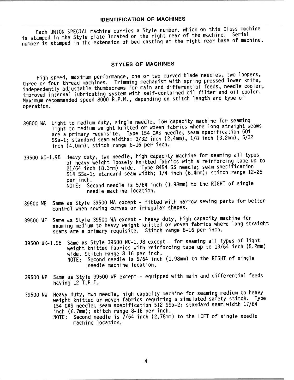
IDENTIFICATION
MACHINES
OF
Each
stamped
is
number
is
High
four
three
or
independently
improved
Maximum
internal
recommended
operation.
39500
39500
WA
WC-1.98
UNION
the
in
stamped
speed,
thread
adjustable
Light
light
a
are
SSa—1;
inch
SPECIAL
Style
the
in
maximum
machines.
lubricating
speed
medium
to
medium
to
primary
standard
(4.0mm);
Heavy
of
duty,
heavy
21/64
SSa—1;
514
inch.
per
NOTE:
machine
plate
extension
performance,
thumbscrews
8000
duty,
weight
requisite.
seam
stitch
weight
inch
(8.3mm)
standard
Second
needle
located
system
two
needle
machine
carries
of
STYLES
Trimming
R.P.M.,
single
knitted
Type
widths:
range
needle,
loosely
wide.
seam
a
on
bed
OF
one
for
with
depending
needle,
3/32
8—16
high
knitted
width;
is
5/64
location.
Style
the
casting
or
number,
right
at
MACHINES
curved
two
mechanism
differential
main
and
self—contained
on
low
GAS
inch.
fabrics
needle;
(2.4mm),
or
154
per
woven
inch
capacity
fabrics
Type
8454
1/4
inch
(1.98mm)
rear
the
with
stitch
capacity
machine
with
GS
needle;
inch
which
the
of
right
blade
spring
oil
length
machine
where
seam
1/8
a
(6.4mm);
to
this
on
machine.
base
rear
needles,
pressed
feeds,
filter
and
and
long
specification
inch
for
(3.2mm),
seaming
reinforcing
seam
specification
stitch
RIGHT
the
Class
two
lower
needle
type
for
straight
of
machine
Serial
of
machine.
loopers,
cooler,
cooler.
oil
of
seaming
504
5/32
all
tape
range
single
knife,
seams
types
up
12—26
to
39500
39500
39500
39500
39500
Same
WE
control
Same
WF
seaming
seams
WK-l.98
WP
Same
having
Heavy
WW
weight
154
inch
NOTE:
Style
as
when
Style
as
medium
are
Same
weight
wide.
NOTE:
as
Style
12
duty,
knitted
needle;
GAS
(6.7mm);
Second
machine
sewing
primary
a
as
knitted
Stitch
Second
needle
T.P.I.
two
39500
39500
to
Style
39500
or
stitch
needle
location.
WA
curves
WA
heavy
requisite.
39500
fabrics
range
needle
machine
WF
needle,
woven
seam
except
or
except
weight
WC—1.98
with
per
8—16
is
5/64
location.
except
capacity
high
fabrics
specification
7/64
8—16
inch
range
is
fitted
-
irregular
heavy
—
knitted
Stitch
except
reinforcing
inch.
inch
equipped
—
requiring
per
(2.78mm)
512
inch.
with
shapes.
duty,
woven
or
range
for
-
(1.98mm)
with
machine
a
SSa—2;
narrow
high
fabrics
8—16
seaming
tape
to
main
for
simulated
standard
the
to
sewing
capacity
per
to
up
the
and
seaming
LEFT
parts
machine
where
inch.
types
all
13/64
RIGHT
differential
medium
safety
width
seam
of
single
for
long
of
inch
of
single
stitch.
better
for
straight
light
(5.2mm)
feeds
heavy
to
17/64
needle
Type
4
Page 5
MACHINE
STYLES
(Continued)
39500
39500
39500
39500
39500
39500
39500
39500
39500
39500
CWA
Same
CWC-1.98
CWE
CWF
Same
Same
CWK—1.98
CWP
SWA
Same
Same
162
SWC-1.98
SWE
Same
162
SWF
Same
162
as
Style
Same
chain
as
Style
Style
as
Same
chain
as
Style
as
Style
SAS)
which
Same
NEEDLE
as
Style
SAS)
which
Style
as
SAS)
which
as
cutter.
as
cutter.
as
(Type
39500
Style
39500
39500
Style
39500
39500
reduces
Style
39500
reduces
39500
reduces
WA
39500
WE
WF
39500
WP
WA
39500
162
WE
WF
except
WC—1.98
except
except
WK—1.98
except
except
needle
WC—1.98
SDS)
except
needle
except
needle
—
-
—
—
cutting.
which
-
cutting.
—
cutting.
fitted
except
fitted
fitted
except
fitted
designed
except
reduces
designed
designed
with
—
with
with
—
with
to
-
needle
to
to
Power
fitted
Power
Power
fitted
Power
use
designed
use
use
hlAir_KlipphDchain
with
Power
“Air—Klipp”
“Air—Klipp”
with
Power
“Air—Klipp”
SHORT,
to
STIFF
use
SHORT,
cutting.
SHORT,
SHORT,
STIFF
STIFF
cutter.
“Air
Klipp”
chain
chain
cutter.
cutter.
“Air—Klipp”
chain
NEEDLE
cutter.
(Type
STIFF
NEEDLE
NEEDLE
(Type
(Type
39500
39500
39500
39500
39500
39500
39500
39500
39500
39500
SWK—1.98
SWP
Same
162
CSWA
Same
CSWC—1.98
CSWF
Same
CSWK—1.98
CSWP
SWAL
Same
Same
seam
SWFL
Same
seam
SWPL
Same
seam
Same
NEEDLE
as
Style
SAS)
which
Style
as
Same
chain
Style
as
Same
chain
as
Style
as
Style
width
Style
as
width
Style
as
width
as
as
as
cutter.
1/8
1/8
1/8
Style
(Type
39500
reduces
39500
Style
cutter.
39500
Style
39500
39500
39500
39500
inch
inch
inch
39500
162
WP
SWA
39500
SWF
39500
SWP
SWA
(3.2mm).
SWF
(3.2mm).
SWP
(3.2mm).
WK—1.98
SDS)
except
needle
except
SWC—1.98
except
SWK-.1.98
except
except
except
except
which
—
cutting.
except
reduces
designed
—
fitted
except
—
fitted
except
—
fitted
—
equipped
—
equipped
—
equipped
—
designed
needle
to
with
—
with
—
with
with
with
with
use
Power
fitted
Power
fitted
Power
to
cutting.
SHORT,
“Air—Klipp”
with
‘Air—Klipp”
with
“Air—Klipp’
Latch
Latch
Latch
SHORT,
use
STIFF
STIFF
NEEDLE
chain
Power
“Air—Klipp”
chain
Power
“Air—Klipp”
chain
Tacker.
Tacker.
Standard
Standard
Tacker. Standard
(Type
cutter.
cutter.
cutter.
5
Page 6
SPEED
RECOMMENDATION
39500
maximum
lower
rated
speed.
recommended
Machine
the
must
machine
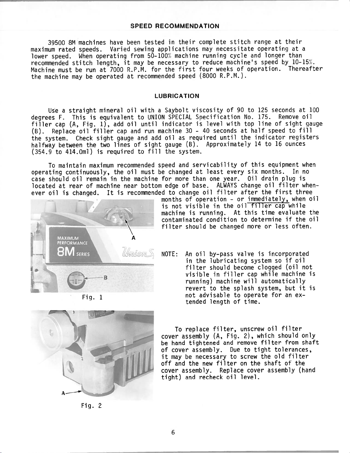
Use
degrees
filler
(B).
the
halfway
(354.9
F.
cap
Replace
system.
between
to
To
maintain
operating
case
ever
located
should
at
oil
8M
machines
speeds.
When
stitch
be
run
may
be
a
straight
This
Fig.
(A,
oil
Check
the
414.Oml)
continuously,
remain
oil
of
rear
is
changed.
have
Varied
operating
length,
7000
at
operated
mineral
is
equivalent
1),
filler
sight
two
required
is
maximum
machine
It
been
sewing
from
it
may
R.P.M.
at
oil
oil
add
and
cap
gauge
lines
of
recommended
the
oil
in
the
machine
near
recommended
is
tested
in
applications
50—100%
be
necessary
the
for
recommended
LUBRICATION
Saybolt
UNION
until
run
sight
fill
a
indicator
machine
add
SPECIAL
oil
gauge
the
with
to
and
to
speed
must
be
changed
for
bottom
edge
months
is
machine
contaminated
filter
their
machine
first
speed
as
system.
and
more
to
change
not
to
viscosity
Specification
is
30
—
required
(B).
servicability
at
than
of
base.
operation
of
visible
is
should
complete
may
necessitate
running
reduce
weeks
four
(8000
R.P.M.).
level
40
seconds
until
Approximately
least
one
year.
ALWAYS
oil
filter
the
in
running.
condition
changed
be
stitch
cycle
machine’s
of
operation.
of
90
No.
with
top
at
the
of
every
Oil
change
after
or
—
oil
this
At
to
more
ranqe
at
operating
longer
and
speed
125
seconds
to
175.
of
line
half
speed
indicator
14
this
six
16
to
equipment
months.
drain
oil
first
the
immediately,
filler
cap
time
determine
or
less
their
at
than
by
10-15%.
Thereafter
Remove
sight
to
registers
ounces
In
plug
filter
when
while
evaluate
if
often.
a
at
oil
fill
when
no
is
when
three
the
100
gauge
oil
the
oil
is
oil
NOTE:
An
in
filter
visible
e_B
running)
revert
Fig.
1
not
tended
replace
To
hand
cover
may
and
assembly
tightened
assembly.
be
the
assembly.
and
cover
be
of
it
off
cover
tight)
A
—-
Fig.
2
-
by—pass
lubricating
the
should
in
to
advisable
length
filter,
(A,
necessary
new
recheck
machine
the
filter
Replace
filler
Fig.
and
oil
valve
become
splash
to
of
unscrew
remove
Due
to
screw
on
level.
system
cap
will
operate
time.
2),
to
the
cover
incorporated
so
clogged
while
automatically
system,
for
oil
which
filter
tight
the
tolerances,
old
shaft
assembly
if
(oil
machine
but
an
filter
should
from
filter
of
oil
it
ex
the
(hand
not
is
is
only
shaft
6
Page 7
NEEDLES
Eich
of
shank,
on
the
shank
and
which
To
sample
packages.
Size
110/044”.
ine
covered
needles
most
their
satisfactory
description,
NEEDLE
154
GAS
162
SAS
needle
is
given
have
needle,
are
TYPE
needle
point,
eye.
orders
A
complete
by
available,
has
lenqth,
shank,
Collectively,
the
on
promptly
or
the
The
type
this
catalog
results.
and
both
groove,
denotes
label
type
order
numbers
but
the
Round
blade,
groove,
chromium
Round
blade,
struck
plated.
a
and
the
sizes
type
the
type
of
all
and
size
would
are
ones
The
shank,
shank,
and
size
finish
largest
and
size
needles
accurately
number
read
as
of
the
given
in
indicated
type
number
available
DESCRIPTION
round
standard
struck
plated.
round
Class
“D”,
groove,
number.
and
other
diameter
number
packaged
filled,
should
follows:
needles
the
of
are
point,
length,
groove,
point,
single
spotted,
The
details.
of
represents
be
recommended
machine
are
those
the
recommended
listed
curved
single
spotted,
curved
groove,
chromium
type
blade,
and
sold
forward
given.
“1000
style
recommended
below:
number
The
size
measured
the
Union
by
the
empty
See
Needles,
for
each
description.
needle,
denotes
number,
midway
complete
Special.
package,
description
Type
style
to
produce
together
SIZES
AVAILABLE
055/022,
070/027,
080/032,
100/040,
125/049,
150/060.
055/022,
01O/07,
080/032,
100/040,
the
symbol,
154
GAS,
of
Other
065/025,
075/029,
090/036,
110/044,
140/054,
065/025,
075/029,
090/036,
110/044.
kind
stamped
between
a
on
mach
the
with
162
SOS
8454
OS
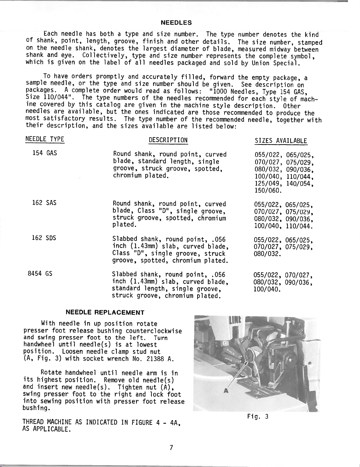
With
presser
and
swing
handwheel
position.
(A,
Fig.
Rotate
its
highest
and
insert
swing
into
presser
sewing
bushing.
THREAD
AS
MACHINE
APPLICABLE.
needle
foot
presser
until
Loosen
3)
new
NEEDLE
in
release
foot
needle(s)
needle
with
socket
handwheel
position.
needle(s).
foot
position
INDICATED
AS
Slabbed
inch
Class
groove,
Slabbed
inch
standard
struck
REPLACEMENT
position
up
bushing
the
to
is
clamp
wrench
until
needle
Remove
Tighten
the
to
with
right
presser
IN
shank,
(1.43mm)
“D”,
round
slab,
single
spotted,
shank,
(1.43mm)
round
slab,
length,
groove,
chromium
rotate
counterclockwise
left.
at
stud
No.
old
and
FIGURE
lowest
nut
21388
arm
needle(s)
nut
lock
foot
Turn
A.
is
(A),
foot
release
4—4A,
point,
curved
groove,
chromium
point,
curved
single
in
.056
blade,
struck
plated.
.056
blade,
groove,
plated.
055/022,
070/027,
080/032.
055/022,
080/032,
100/040.
Fig.
065/025,
075/029,
070/027,
090/036,
3
7
Page 8
C,)
Ui
D
I
4
Ui
LI
z
-J
0
0
C-)
z
4
z
0
w
0
-J
w
Cl)
u-i
>
Cl)
z
I-
4
C.)
D
-J
I—
D
0
-J
0
8
Page 9
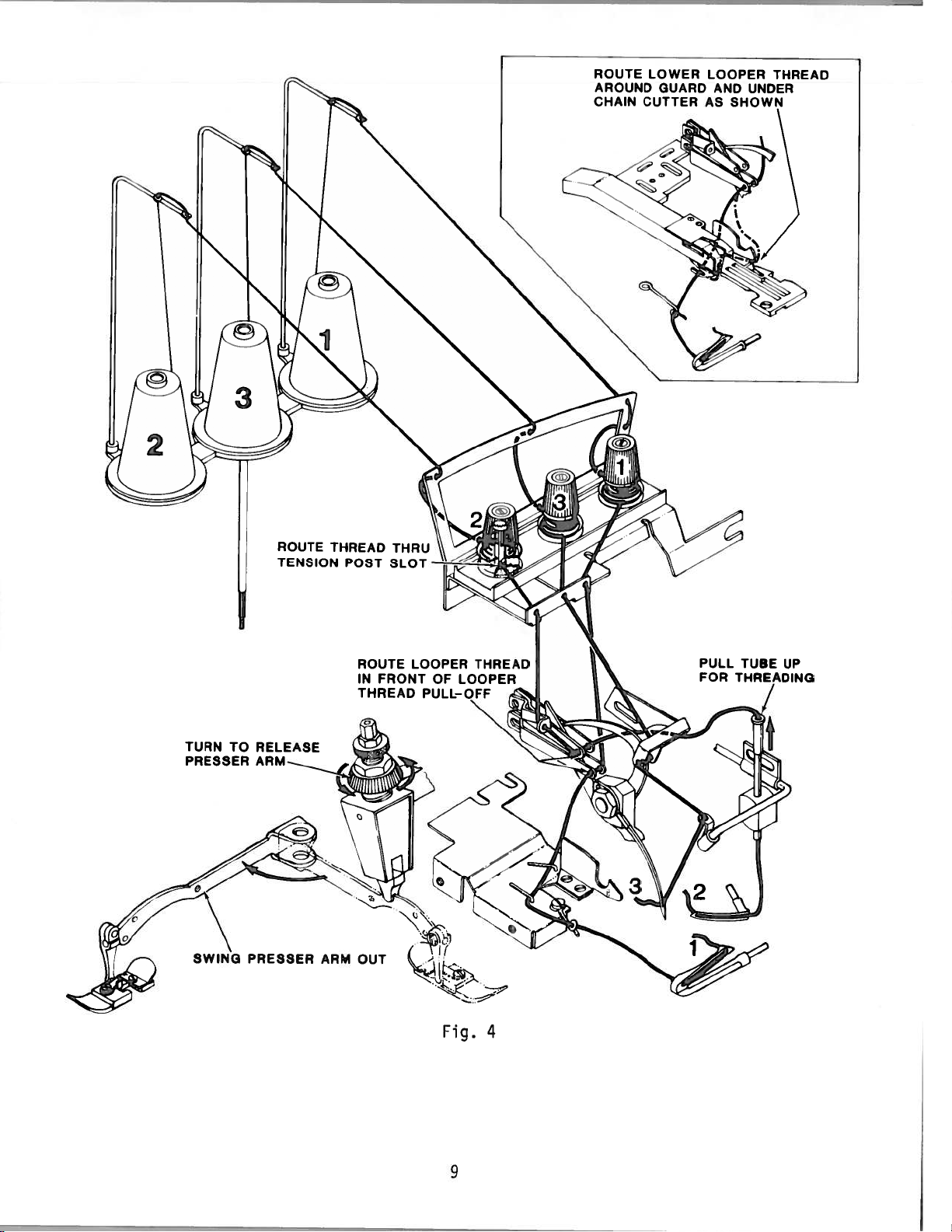
ROUTE
AROUND
CHAIN
LOWER
GUARD
CUTTER
LOOPER
AND
AS
SHOWN
THREAD
UNDER
TURN
PRESSER
TO
PRESSER
ROUTE
TENSION
RELEASE
ARM
THREAD
POST
ARM
SLOT
ROUTE
IN
FRONT
THREAD
OUT
LOOPER
OF
PULL-OFF
THREAD
LOOPER
UP
DING
4
Fig.
9
Page 10
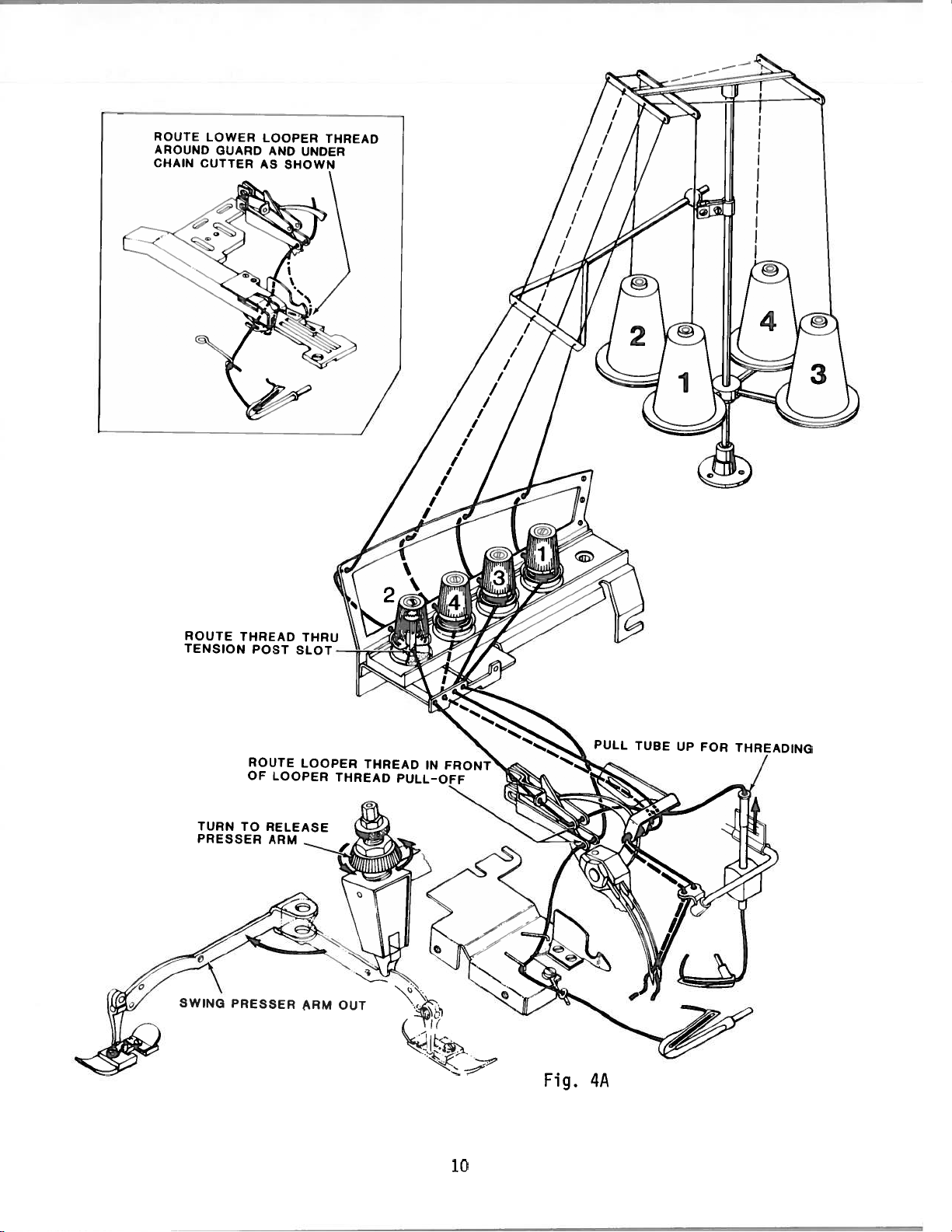
ROUTE
AROUND
CHAIN
LOWER
GUARD
CUTTER
LOOPER
AND
AS
SHOWN
THREAD
UNDER
TURN
PRESSER
SWING
TO
RELEASE
PRESSER
ARM
ARM
OUT
10
Fig.
PULL
4A
TUBE
UP
FOR
Page 11
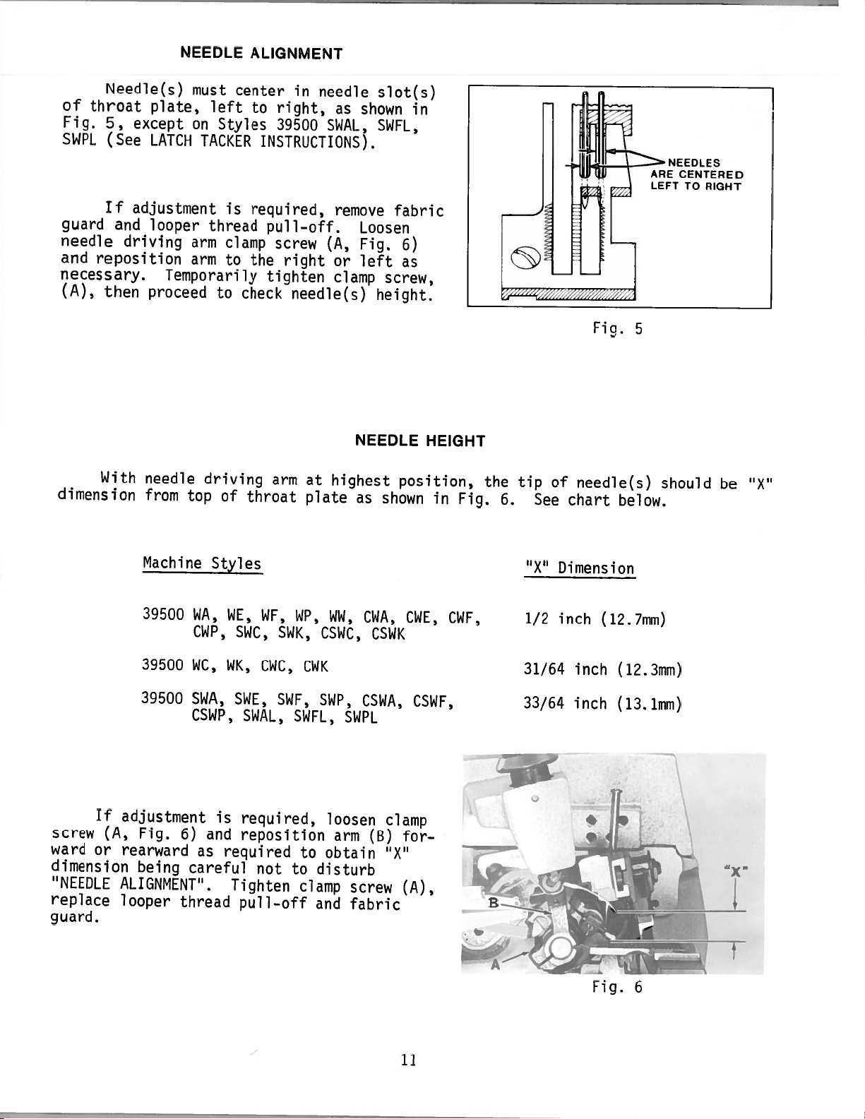
NEEDLE
ALIGNMENT
Needle(s)
of
throat
Fig.
5,
SWPL
guard
needle
and
necessary.
(A),
dimension
(See
If
reposition
then
With
plate,
except
LATCH
adjustment
and
looper
driving
proceed
needle
from
must
left
on
Styles
TACKER
is
thread
arm
clamp
arm
to
Temporarily
to
driving
top
of
center
to
required,
the
check
throat
in
needle
right,
39500
INSTRUCTIONS).
pull—off.
screw
right
tighten
needle(s)
arm
at
plate
as
shown
SWAL,
remove
Loosen
(A,
Fig.
left
or
clamp
NEEDLE
highest
as
slot(s)
in
SWFL,
fabric
6)
as
screw,
height.
position,
shown
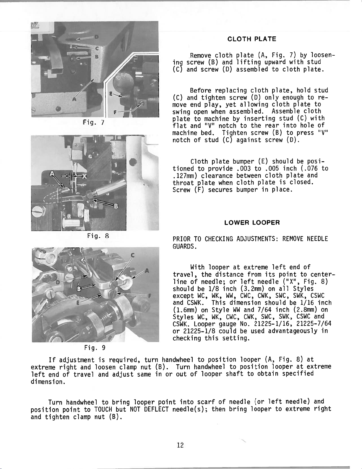
HEIGHT
in
Fig.
the
6.
tip
See
of
chart
Fiq.
needle(s)
below.
5
LEFT
should
TO
RIGHT
be
“X”
If
screw
ward
dimension
‘NEEDLE
replace
guard.
(A,
or
Machine
39500
39500
39500
adjustment
Fig.
rearward
being
ALIGNMENT”.
looper
WA,
CWP,
WC,
SWA,
CSWP,
6)
and
as
careful
thread
Styles
is
WE,
WF,
SWC,
WK,
CWC,
SWE,
SWAL,
required,
reposition
required
not
Tighten
pull—off
WP,
SWK,
CWK
SWF,
SWFL,
to
to
clamp
WW,
CSWC,
SWP,
SWPL
loosen
arm
obtain
disturb
screw
and
fabric
CWA,
CSWK
CSWA,
clamp
(B)
“X”
CWE,
CSWF,
for
(A),
CWF,
“X”
1/2
31/64
33/64
Dimension
inch
inch
inch
(12.7mm)
(12.3mm)
(13.1mm)
1
11
Fig.
6
Page 12
in
(C)
Remove
screw
and
(B)
screw
cloth
and
(D)
CLOTH
plate
lifting
assembled
PLATE
(A,
upward
Fig.
to
7)
with
cloth
by
stud
plate.
loosen—
_z]_
Fig.
L
Before
and
(C)
end
move
swing
plate
flat
machine
notch
open
to
and
of
Cloth
tioned
.127mm)
throat
Screw
8
PRIOR
(F)
TO
replacing
tighten
play,
when
machine
‘V’
notch
bed.
stud
plate
to
provide
clearance
plate
when
secures
CHECKING
screw
yet
assembled.
Tighten
(C)
LOWER
cloth
(D)
allowing
inserting
by
to
the
screw
against
bumper
.003
to
between
cloth
bumper
LOOPER
ADJUSTMENTS:
only
rear
screw
(E)
.005
cloth
plate
in
plate,
cloth
Assemble
(B)
should
place.
hold
enough
plate
into
to
(D).
(C)
press
stud
be
inch
plate
closed.
is
REMOVE
to
cloth
with
hole
posi—
(.076
and
NEEDLE
stud
re
to
of
“V’
to
GUARDS.
If
extreme
left
end
dimension.
Turn
position
and
tighten
adjustment
right
of
and
travel
handwheel
point
to
clamp
Fig.
TOUCH
9
is
loosen
and
to
nut
required,
clamp
adjust
bring
but
(B).
nut
same
looper
NOT
turn
handwheel
(B).
in
or
point
DEFLECT
With
travel,
line
of
should
except
and
CSWK.
(1.6mm)
Styles
CSWK.
or
Looper
21225—1/8
checking
Turn
out
handwheel
of
into
needle(s);
looper
the
needle;
be
WC,
on
WC,
this
position
to
looper
scarf
distance
1/8
WK,
This
Style
WK,
gauge
could
of
then
at
or
inch
WW,
dimension
14W
CWC,
setting.
to
shaft
needle
bring
extreme
from
left
needle
(3.2mm)
CWC,
CWK,
and
7/64
CWK,
No.
21225—1/16,
be
used
looper
position
to
obtain
(or
looper
end
left
its
point
(“X”,
all
on
SWC,
should
be
inch
SWC,
SWK,
advantageously
Fig.
(A,
looper
specified
left
to
needle)
extreme
of
to
center
Fig.
Styles
SWK,
1/16
CSWC
inch
(2.8mm)
and
CSWC
21225—7/64
at
8)
at
extreme
and
right
8)
on
in
12
Page 13
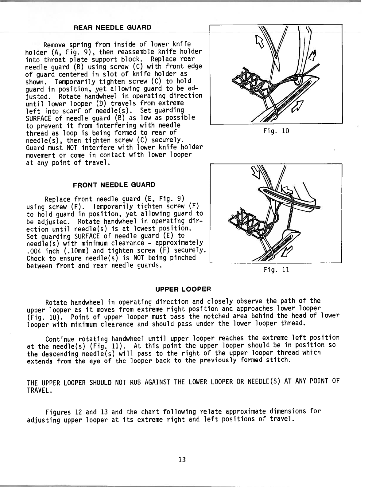
REAR
NEEDLE
GUARD
Remove
holder
throat
into
needle
of
guard
guard
shown.
guard
in
justed.
until
left
lower
into
SURFACE
prevent
to
thread
needle(s),
Guard
must
movement
at
any
Replace
using
to
be
screw
hold
adjusted.
ection
Set
guarding
needle(s)
inch
.004
Check
to
between
spring
Fig.
(A,
plate
(B)
centered
Temporarily
position,
Rotate
looper
scarf
needle
of
from
it
as
loop
then
NOT
come
or
guard
of
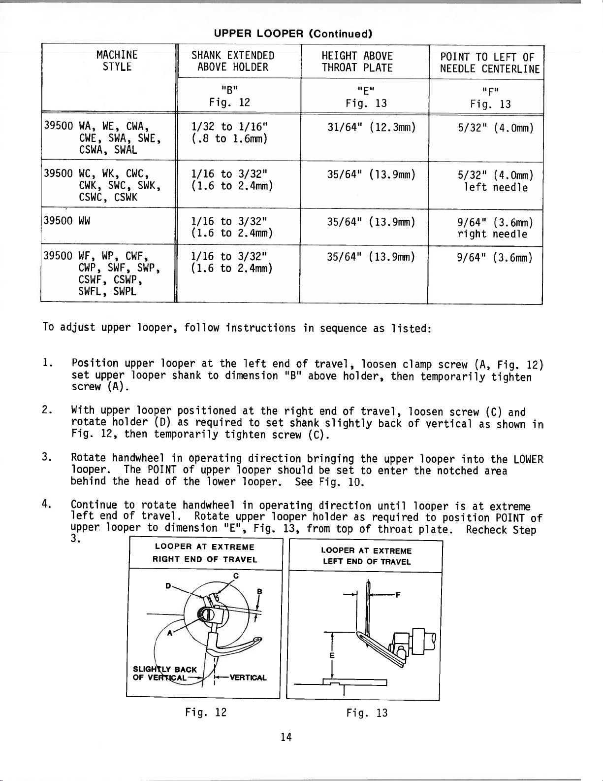
FRONT
front
(F).
in
point
Rotate
until
needle(s)
SURFACE
with
(.10mm)
ensure
front
and
from
then
9),
support
using
slot
in
tighten
yet
handwheel
CD)
needle(s).
of
guard
interfering
being
is
tighten
interfere
contact
in
travel.
NEEDLE
needle
Temporarily
position,
handwheel
of
minimum
and
needle(s)
rear
inside
reassemble
block.
screw
of
allowing
in
travels
(B)
formed
screw
with
guard
yet
at
is
needle
clearance
tighten
is
needle
of
with
(C)
knife
screw
guard
operating
from
Set
low
as
with
to
(C)
lower
with
GUARD
(E,
tighten
allowing
in
lowest
guard
screw
NOT
guards.
lower
knife
knife
Replace
front
holder
to
to
hold
be
(C)
direction
extreme
guarding
possible
as
needle
of
rear
securely.
knife
lower
looper
Fig.
screw
guard
operating
position.
(E)
—
approximately
securely.
(F)
being
pinched
holder
rear
edge
as
ad
holder
9)
to
(F)
dir
to
Fig.
Fig.
10
11
Rotate
upper
(Fig.
looper
10).
looper
Continue
at
the
the
descending
extends
THE
UPPER
TRAVEL.
Figures
adjusting
handwheel
Point
with
minimum
needle(s)
from
LOOPER
upper
as
it
rotating
needle(s)
the
12
and
looper
in
moves
upper
of
clearance
handwheel
(Fig.
eye
11).
of
SHOULD
13
and
at
operating
from
looper
At
will
looper
the
RUB
NOT
the
its
extreme
must
should
and
until
this
pass
AGAINST
chart
extreme
UPPER
direction
right
pass
upper
point
the
to
back
to
THE
following
right
LOOPER
and
position
the
pass
looper
the
right
the
LOWER
and
13
closely
notched
under
upper
of
the
previously
LOOPER
relate
left
observe
approaches
and
area
lower
the
reaches
looper
upper
formed
OR
approximate
positions
the
lower
behind
the
looper
extreme
the
should
looper
be
thread
stitch.
NEEDLE(S)
dimensions
travel.
of
path
head
thread.
left
in
AT
of
the
looper
of
position
position
which
POINT
ANY
for
lower
so
OF
Page 14
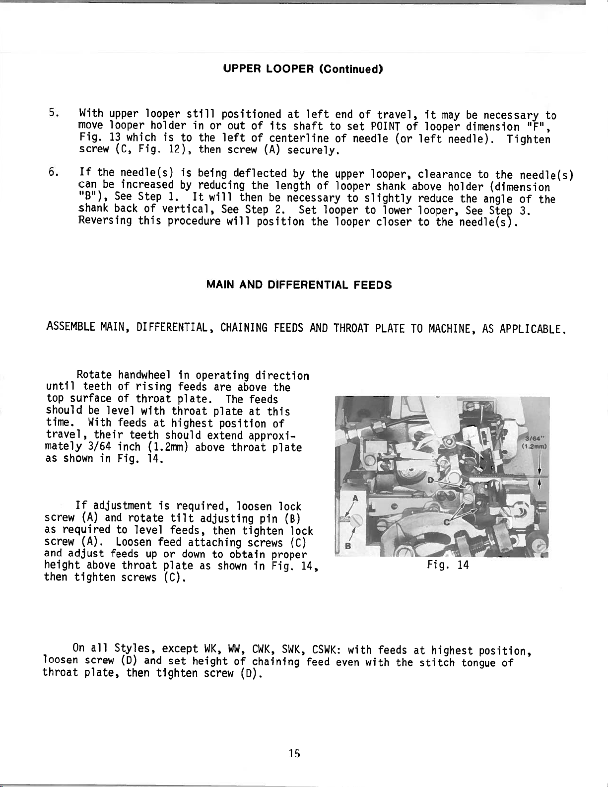
UPPER
LOOPER
(Contirwed)
39500
39500
39500
39500
To
adjust
MACHIN[
STYLE
WA,
WE,
CWE,
CSWA,
WC,
WK,
CWK,
CSWC,
WW
WP,
WE,
CWP,
CSWF,
SWFL,
upper
CWA,
SWA,
SWAL
CWC,
SWC,
CSWK
CWF,
SWF,
CSWP,
SWPL
SWE,
SWK,
SWP,
looper,
SHANK
ABOVE
1/32
(.8
1/16
(1.6
1/16
(1.6
1/16
(1.6
follow
EXTENDED
HOLDER
Fig.
12
to
1/16”
to
1.6mm)
to
3/32”
to
2.4mm)
to
3/32”
to
2.4mm)
to
3/32”
to
2.4mm)
instructions
in
sequence
HEIGHT
THROAT
Fig.
31/64”
35/64”
35/64”
35/64”
ABOVE
PLATE
13
(12.3mm)
(13.9mm)
(13.9mm)
(13.9mm)
as
listed:
POINT
NEEDLE
Fig.
5/32”
5/32”
left
9/64”
right
9/64”
TO
LEFT
OF
CENTERLINE
F”
13
(4.0mm)
(4.0mm)
needle
(3.6mm)
needle
(3.6mm)
4.
1.
2.
3.
Position
set
upper
screw
With
upper
rotate
Fig.
12,
Rotate
looper.
behind
Continue
left
end
upper
3.
upper
looper
(A).
looper
holder
then
handwheel
The
the
head
to
of
looper
looper
CD)
temporarily
POINT
of
rotate
travel.
to
dimension
LOOPER
RIGHT
at
shank
positioned
as
required
operating
in
of
upper
the
handwheel
Rotate
AT
END
the
dimension
to
tighten
lower
“E”,
EXTREME
OF
TRAVEL
left
at
to
direction
looper
looper.
in
upper
C
end
the
set
screw
should
operating
looper
Fig.
“B
right
shank
13,
of
above
(C).
bringing
See
from
travel,
end
slightly
set
be
Fig.
direction
holder
top
LOOPER
LEFT
loosen
holder,
of
travel,
the
to
10.
as
of
AT
END
back
upper
enter
until
required
throat
EXTREME
OF
TRAVEL
then
clamp
temporarily
loosen
of
vertical
looper
the
looper
to
plate.
screw
screw
into
notched
is
position
(A,
tighten
(C)
as
the
area
at
extreme
POINT
Recheck
Fig.
and
shown
LOWER
Step
12)
in
of
Fig.
12
Fig.
14
13
Page 15
2:
5.
With
move
Fig.
screw
6.
If
the
can
“B”),
shank
Reversing
ASSEMBLE
upper
looper
13
which
(C,
needle(s)
be
increased
See
back
MAIN,
looper
holder
Fig.
Step
of
this
still
in
is
to
12),
is
by
1.
It
vertical,
procedure
or
the
then
being
reducing
will
MAIN
DIFFERENTIAL,
UPPER
positioned
out
left
screw
LOOPER
of
of
(A)
deflected
the
then
See
Step
will
position
DIFFERENTIAL
AND
CHAINING
left
at
its
shaft
centerline
securely.
by
length
be
necessary
2.
Set
FEEDS
(Continued)
end
to
of
the
upper
of
looper
looper
looper
the
AND
THROAT
of
set
needle
to
FEEDS
travel,
POINT
looper,
shank
slightly
lower
to
closer
PLATE
of
(or
it
looper
left
clearance
above
reduce
looper,
the
to
MACHINE,
TO
may
needle).
holder
the
needle(s).
be
necessary
dimension
to
the
(dimension
angle
See
Step
AS
APPLICABLE.
“F”,
Tighten
needle(s)
of
3.
to
the
until
top
should
time.
travel,
mately
as
screw
as
required
screw
and
height
then
loosen
throat
Rotate
teeth
surface
shown
If
(A)
(A).
adjust
tighten
On
screw
plate,
handwheel
of
of
be
level
With
feeds
their
3/64
in
inch
Fig.
adjustment
and
to
Loosen
feeds
above
all
Styles,
rising
throat
with
teeth
rotate
level
throat
screws
CD)
then
throat
at
highest
should
(1.2mm)
14.
is
tilt
feeds,
feed
up
or
plate
(C).
except
and
set
tighten
operating
in
feeds
plate.
extend
above
required,
adjusting
attaching
down
as
WK,
height
screw
are
The
plate
position
throat
then
obtain
to
shown
WW,
of
direction
above
feeds
at
approxi-.
loosen
tighten
screws
in
CWK,
chaining
(D).
this
pin
the
of
plate
lock
(B)
lock
(C)
proper
Fig.
SWK,
14,
CSWK:
feed
with
even
with
feeds
the
at
stitch
Fig.
highest
14
tongue
position,
of
15
Page 16
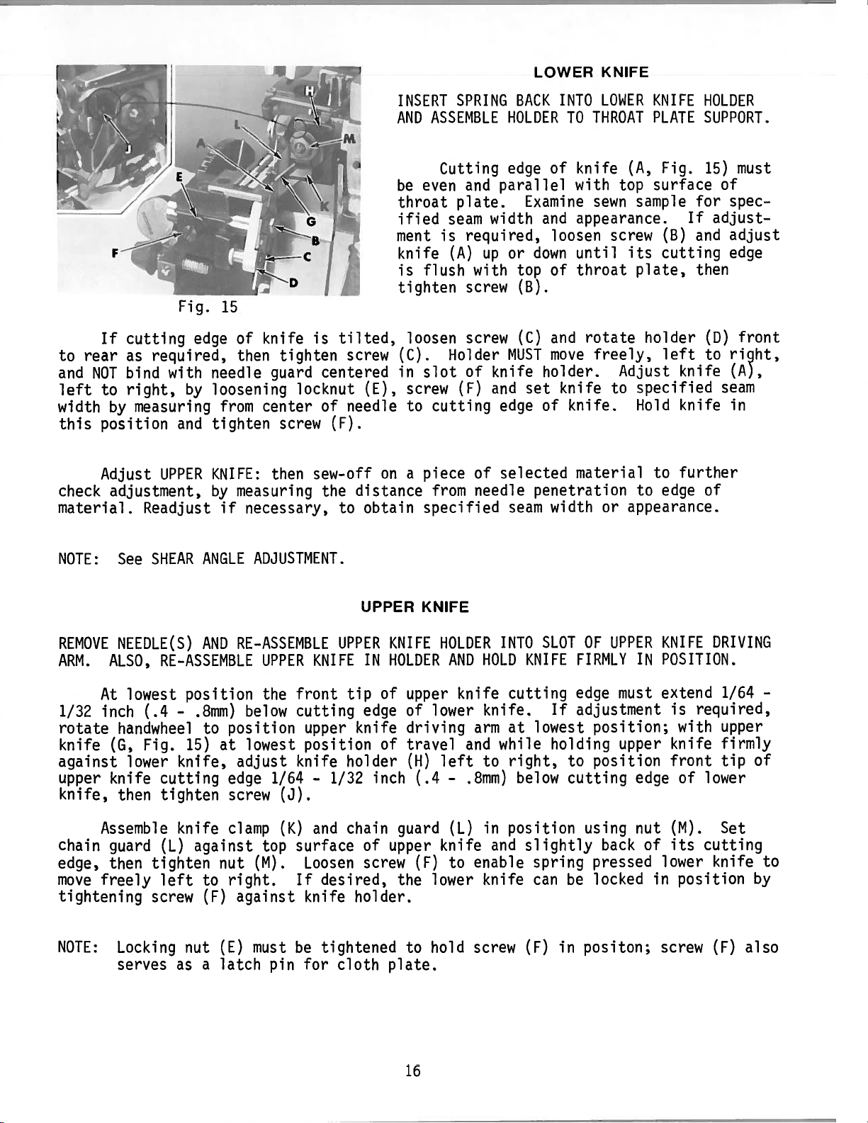
LOWER
KNIFE
rear
to
and
NOT
left
to
width
this
position
Adjust
check
material.
If
cutting
required,
as
bind
right,
measuring
by
adjustment,
Readjust
Fig.
edge
with
by
and
UPPER
15
of
then
needle
loosening
from
tighten
KNIFE:
by
measuring
if
necessary,
knife
tighten
guard
center
screw
then
is
centered
locknut
of
(F).
sew-off
the
tilted,
screw
needle
distance
obtain
to
(E),
INSERT
AND
be
throat
ified
ment
knife
is
tighten
loosen
(C).
in
screw
to
a
on
SPRING
ASSEMBLE
Cutting
even
and
plate.
seam
is
required,
up
(A)
flush
with
screw
screw
Holder
slot
of
(F)
cutting
from
of
needle
piece
specified
BACK
HOLDER
edge
parallel
Examine
width
or
top
(B).
(C)
MUST
knife
and
set
edge
selected
seam
INTO
THROAT
TO
of
knife
with
sewn
and
appearance.
loosen
down
until
of
throat
and
rotate
move
freely,
holder.
knife
of
knife.
material
penetration
width
LOWER
(A,
top
sample
screw
its
plate,
holder
Adjust
to
specified
Hold
to
or
appearance.
KNIFE
PLATE
Fig.
surface
If
(B)
cutting
left
knife
knife
to
further
edge
HOLDER
SUPPORT.
must
15)
of
spec
for
adjust
adjust
and
edge
then
front
(D)
ri9ht,
to
(A),
seam
in
of
NOTE:
REMOVE
ARM.
ALSO,
At
1/32
inch
rotate
knife
(G,
against
upper
knife
knife,
Assemble
chain
edge,
move
guard
then
freely
tightening
NOTE:
SHEAR
See
NEEDLE(S)
RE-ASSEMBLE
(.4
position
—
lowest
handwheel
Fig.
15)
lower
knife,
cutting
then
tighten
knife
CL)
tighten
left
screw
Locking
serves
nut
as
ANGLE
AND
.8mm)
position
to
at
edge
screw
clamp
against
nut
right.
to
(F)
CE)
a
latch
ADJUSTMENT.
RE-ASSEMBLE
UPPER
the
below
KNIFE
front
cutting
upper
1/64
position
knife
—
1/32
lowest
adjust
(J).
(K)
and
surface
top
(M).
against
must
pin
Loosen
If
desired,
knife
be
tightened
for
UPPER
UPPER
IN
tip
edge
knife
holder
inch
chain
of
screw
holder.
cloth
KNIFE
KNIFE
HOLDER
of
upper
of
driving
of
travel
(H)
(.4
guard
upper
(F)
the
to
plate.
HOLDER
AND
knife
lower
arm
and
left
—
.8mm)
(L)
knife
to
enable
lower
screw
hold
INTO
HOLD
cutting
knife.
at
while
right,
to
in
position
and
knife
SLOT
KNIFE
lowest
below
slightly
spring
can
(F)
OF
FIRMLY
edge
If
adjustment
holding
to
cutting
using
be
positon;
in
UPPER
IN
must
position;
upper
position
edge
nut
back
pressed
locked
KNIFE
POSITION.
extend
is
with
knife
front
of
CM).
of
its
lower
in
position
screw
DRIVING
1/64
required,
upper
firmly
tip
lower
Set
cutting
knife
(F)
—
of
to
by
also
16
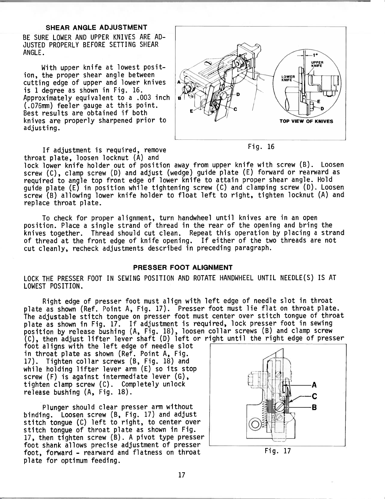
Page 17
SURE
BE
JUSTED
ANGLE.
SHEAR
LOWER
PROPERLY
ANGLE
AND
BEFORE
ADJUSTMENT
UPPER
KNIVES
SETTING
AD
ARE
SHEAR
1
With
the
ion,
cutting
is
1
degree
Approximately
(.076mm)
Best
knives
adjusting.
throat
lock
screw
required
guide
screw
replace
position.
knives
of
thread
cut
cleanly,
proper
edge
feeler
results
are
If
adjustment
plate,
lower
(C),
to
plate
(B)
throat
To
check
together.
upper
allowing
at
of
as
equivalent
are
properly
loosen
knife
clamp
angle
CE)
for
Place
the
recheck
knife
shear
upper
shown
gauge
obtained
holder
screw
top
in
plate.
proper
a
single
Thread
front
at
angle
and
Fig.
in
at
sharpened
is
required,
locknut
out
CD)
front
position
lower
edge
adjustments
lowest
between
lower
16.
a
if
and
knife
.003
point.
both
prior
(A)
of
edge
while
of
position
adjust
holder
knife
to
this
alignment,
strand
should
posit
knives
inch
to
remove
and
of
lower
tightening
turn
of
thread
clean.
cut
described
away
(wedge)
knife
to
float
handwheel
in
opening.
from
guide
screw
the
Repeat
in
preceding
to
left
If
upper
attain
(C)
until
rear
this
either
plate
to
of
Fig.
knife
(E)
proper
clamping
and
right,
knives
the
operation
of
the
paragraph.
16
with
forward
shear
tighten
are
opening
two
screw
screw
in
by
threads
(B).
or
rearward
angle.
locknut
an
bring
and
placing
(D).
open
are
Loosen
Hold
Loosen
(A)
the
a
strand
as
and
not
LOCK
THE
LOWEST
Right
plate
The
plate
position
(C),
foot
in
17).
while
screw
tighten
release
binding.
stitch
stitch
17,
foot
foot,
plate
as
adjustable
as
then
aligns
throat
Tighten
holding
Plunger
then
shank
forward
for
PRESSER
POSITION.
edge
shown
shown
release
by
adjust
with
plate
is
(F)
clamp
tongue
tongue
against
bushing
should
Loosen
tighten
allows
optimum
FOOT
of
(Ref.
stitch
in
lifter
the
as
collar
lifter
screw
(A,
screw
(C)
of
throat
screw
-
rearward
IN
presser
Point
tongue
Fig.
bushing
left
shown
screws
lever
intermediate
(C).
Fig.
clear
left
precise
feeding.
SEWING
foot
A,
17.
lever
edge
(Ref.
arm
Completely
18).
presser
Fig.
(B,
right,
to
plate
(B).
adjustment
and
PRESSER
POSITION
must
Fig.
presser
on
If
adjustment
Fig.
(A,
shaft
of
Point
(B,
Fig.
CE)
17)
as
A
pivot
flatness
17).
(D)
needle
so
lever
arm
and
center
to
shown
type
FOOT
align
foot
18),
left
Fig.
A,
18)
its
(G),
unlock
without
adjust
in
presser
of
on
ALIGNMENT
ROTATE
AND
with
Presser
must
required,
is
loosen
or
slot
and
stop
over
Fig.
presser
throat
HANDWHEEL
edge
left
must
foot
center
collar
right_until
over
lock
screws
of
lie
presser
the
—
UNTIL
needle
flat
stitch
(B)
right
Fig.
NEEDLE(S)
slot
on
foot
and
in
throat
tongue
in
clamp
edge
17
throat
plate.
of
sewing
screw
of
presser
-A
-c
-B
IS
throat
AT
-
17
Page 18

116”
(1.6mm>
Fig.
18
-.
/
p
PRESSER
Lift
and
rotate
Upper
any
loosen
screw
with
Loosen
upper
looper
point
locknut
(J)
upper
locknut
end
approximately
lifter
rise,
FOOT
lever
then
PRESSURE
PRESSER
presser
handwheel
must
of
travel.
(H,
so
presser
looper,
(K)
of
lifter
1/16
before
tighten
foot
in
not
Fig.
foot
then
and
lever
inch
presser
locknut
FOOT
to
LIFTER
highest
operating
contact
If
adjustment is
18)
and
will
tighten
set
stop
arm
(1.6mm)
foot
(K).
presser
adjust
not
locknut
screw
so
there
free
starts
position
direction.
foot
required,
stop
interfere
(F)
is
motion
at
(H).
on
in
to
spring
If
adjustment
and
18)
less
NOTE:
Sufficient
pressure
differential
and
turn
pressure,
Adjusting
Plunger
When
against
ment
is
adjusting
then
must
release
throat
must
pressure
will
required,
feeds
tighten
screw
clear
bushing
be
made.
cause
are
screw
CM)
plate.
must
feeds
rotate
positioned
(M)
locknut
will
presser
is
maintained
be
and
clockwise
effect
locked
If
these
presser
handwheel
below
(L).
the
arm
when
in
conditions
to
foot
in
throat
for
function
pressure
position,
feed
work
to
operating
plate.
more
pressure
of
release
presser
do
wear
pressure
not
uniformly.
prematurely
direction
Loosen
or
bushing
foot
exist
Excessive
when
until
locknut
counterclockwise
release
must
the
following
is
be
bushing
unlocked.
held
chaining.
both
(L,
main
Fig.
for
(A).
firmly
adjust
Lock
(N)
screw
and
(M)
presser
adjust
as
shown
nut
foot
(P)
in
in
up
Fig.
position
or
down
18.
so
Hold
with
its
nut
pressure
under
(P)
surface
in
release
position
18
bushing
is
and
1/16
inch
tighten
(A);
loosen
(1.6mm)
capnut
capnut
above
(N).
Page 19

The
usually
per
inch
distance
ing
above
The
to
a
great
The
differential
independent
gather
or
stitched.
On
(A,
Fig.
longest
indicates
To
clockwise
desired
tial
feeds,
SETTING
actual
measured
of
seam.
feeds
the
resulting
extent
of
stretch
the
graduated
19)
the
stitch
shortest
adjust
to
increase
stitch
also
stitch
as
travel
throat
feed
the
forward
length
stitch
length
check
STITCH
the
This
stitch
by
main
the
stitch
length
number
is
with
plate.
travel
travel
feed
fabric
scale
marking
and
length
feed
is
obtained
clearance
LENGTH
produced
of
determined
their
length
of
the
can
and
prior
of
indicator
rear
the
length.
turn
travel
is
stitches
by
teeth
is
be
is
“L”
both
or
check
between
protrud
determined
main
marking
feed.
adjusted
used
to
being
indicates
main
counterclockwise
the
sewn
the
to
plate
‘S’
and
clearance
the
differential
throat
to decrease
between
plate
thumbscrews
the
both
and
Fig.
feed
main
feeds.
19
travel.
and
(B
and
differen—
C)
After
If
an
the
handwheel
the
way
to
clearance
(18-20
MECHANISM.
differential
the
plate
stitch
thread
ed
barely
the
loosen
tion
If
bed
Needle
in
Moving
eyelet
and
cm/kg).
desired,
directly
and
length
cam
the
touch
screw
tighten
screw
adjustment
in
rear.
the
is
obtained.
feed
lower
pull-off
down
during
thread
needle
the
(C)
knife
slot,
eyelet
and
is
operating
Loosen
If
clearance
thumbscrews
or
by
above
and
screw
support
machine
controlled
is
(B).
front
thread
up
forward
position
the
(C).
necessary,
direction
nut
Hold
ferrule
cannot
can
tightening
main
bracket.
operation.
NEEDLE
Needle
to
cam
back
and
acts
thread
set
CD)
be
locked
be
pressure
feed
by
needle
thread
back.
pull—off
increases
the
the
until
and
rotate
in
position
obtained,
stitch
This
THREAD
eyelet
Raise
when
reverse.
eyelet
feeds
the
differential
eccentric
in
position
plug
regulating
will
CONTROL
thread
is
or
lower
needle
the
To
(A)
as
to
and
See
screw
prevent
eyelet
set
carrier
needle
adjust
required.
have
the
ferrule
torque
SETTING
by
tightening
for
the
screw
accidental
(A,
so
the
the
eyelet
thread
needle
same
feed
nut
DIFFERENTIAL
to
Fig.
securing
is
Hold
is
to
main
the
to
in
in
thread
travel,
positioned
(E)
16—17
nut
feed,
rear
changing
20)
and
screw
have
its
lowest
the
stitch,
eyelet
until
control,
then
in.
FEED
(F)
located
of
needle
needle
in
turn
all
maximum
lbs.
for
the
in
throat
of
is
center
thread
position.
moving
posi
19
Page 20

LOOPER
THREAD
PULL-OFF
When
will
be
looper
at
its
centered
Loosen
ing
slot
tighten
adjusting
eyelet
C
I
I
a
thread
extreme
screw
and
a
little
in
and
slot
normal
is
its
screw
set
back
Fig.
slack
held
left
adjusting
eyelet
(A).
and
of
20
amount
end
(A,
Loosen
set
lower
when
in
of
Fig.
in
eyelet
of
needle(s)
a
straight
travel.
slot
21).
a
screw
looper
LOOPER
looper
and
Center
horizontal
(C).
so
it
thread
THREAD
thread
line
The
set
rests
(0,
(B)
take—up
Loosen
pull—off
driving
obtained.
sure
shaft.
at
is
to
auxiliary
slightly
lower
position.
Center
on
eyelet
Clearance
Fig.
should
screws
to
CONTROL
is
drawn,
highest
the
looper
upper
the
eye.
20)
be
of
lever
shaft
take
lower
upper
above
top
between
and
only
looper
(E)
(F)
until
Before
up
upper
position.
looper,
a
thread
Hold
looper
surface
needle
enough
thread
rotate
and
front
proper
tightening
all
end
and
with
looper
horizontal
eyelet
eyelet
thread
of
looper
thread
to
as
back
to
clearance
play
lower
Position
the
thread
position.
(B)
(B)
in
eyelet
lower
thread
cam
ensure
shown
looper
screws
in
looper
lower
guide
in
position
looper
pull-off
in
on
needle
guide
its
CD)
pull-off
proper
Fig.
thread
needle
is
(E)
drive
threads
so
looper
should
adjust
and
in
thread
20.
be
the
be
its
guide
(D)
its
in
a
Center
so
auxiliary
and
set
To
extreme
straight
it
auxiliary
slightly
is
frame
end
left
line
Fig.
upper
lower
of
to
21
upper
above
looper
thread
travel
the
looper
lower
horizontal
a
thread
eyelet
and
looper.
thread
guide
(F)
position
guide
position.
CE)
loosen
the
Tighten
NOTE:
in
CE)
position
in
screw
eyelet
screw
Moving
increases
in
the
reduces
system.
its
Hold
(G)
so
(G).
eyelets
the
system
the
adjusting
lower
and
and
looper
the
(B
amount
and
amount
looper
tighten
move
and
moving
of
slot
lower
thread
D)
of
thread
and
thread
screw
looper
to the
looper
them
set
eyelet
(C).
is
held
rear
thread
forward
the
in
to
20
Page 21

POWER
“AIR_KLIPP”r
CHAIN
CUTTER
ADJUSTMENTS
SETTING
The
after
air
replacing
line
VALVES)
finger,
stops.
With
lower
from
loosen
knife
the
screws
positioned
right.
inch
(.4mm)
CAUTION!
knife
CROSS
cross
KNIFE
or
connected
depress
treadle
carefully
treadle
the
to
front
of
(B),
far
to
Retighten
clearance
Check
does
to
not
“AIR—KLIPP”
slight
at
point
OVER
over
sharpening
to
air
press
still
upper
the
upper
reposition
left
screws
between
ensure
strike
chain
clearance
(D).
is
motor
until
against
depressed,
knife
knife
slightly
or
(B)
that
against
cutter
must
set
knives.
air
is
air
and
front
lower
the
at
With
“AIR—KLIPP”
for
motor
moving
the
check
positioned
as
shown
motor
the
to
recheck
edge
knife
inside
tube.
be
provided
factory,
sewing
begins
drive
the
in
slightly
(C)
right
cross
of
air
of
A
however
motor
chain
operate,
to
link
knife
correctly,
Fig.
if
over.
tube
cross
22.
to
lower
and
adjustment
switch
cutter
(A,
over.
when
If
the
knife
There
rear
in
(See
and
in
22)
Fig.
The
the
adjustment
left
is
should
edge
will
“OFF”
SETTING
out.
until
cross
lower
is
lower
if
positioned
always
of
throat
necessary
be
position
PRESSURE
With
air
over
knife
required,
knife
be
fore
motor
of
is
2/3
is
too
1/64
plate.
and
the
far
SETTING
If
and
turn
wise
(a
operating
ing
with
are
cutting.
the
thread,
(F)
counterclockwise
lock
with
SETTING
Torsion
lifted
to
the
the
right
over
left
SETTING
Regulate
chain
cutter
Regulate
suction,
cutter
knives.
KNIFE
CUTTING
adjustment
knife
piece
knife
amount
lever
lower
small
a
As
shear
the
CE).
nut
KNIFE
PRESSURE
spring
knife.
the
(away
(towards
PRESSURE
valve
approximately
to
so
on
that
valve
yet
is
required,
adjusting
at
(G),
thread
of
soon as
angle
approximately
(H)
from
lower
lower
VALVES
on
pneumatic
pneumatic
the
time)
a
continuously
to
the
knives
is zero,
initially
More
pressure
knife);
knife).
control
FABRIC
loosen
screw
while
if
see
should
control
20—22
TO
(F)
knives
fail
turn
1/4
less
psi
device
BE
CE)
nut
clock
manually
check
to
screw
turn
be
be
can
pressure
device
(1.5
for
SEWN
will
cut
and
horizontal
obtained
for
when
bar)
the
not
by
—
by
air
air
suction
cut
be
in
its
bending
bending
motor
motor
air
by
Fig.
22
state
free
spring
spring
of
the
operating.
is
obtain
to
the
“AIR—KLIPP”
and
then
slightly
(H)
slightly
“AIR—KLIPP”
maximum
chain
to
21
Page 22

AC
23
Fig.
22
Page 23

1.
Position
(C)
and
washer
all
up
Shaft
end
(C)
components
washer
insert
(A)
should
ADJUSTING
(A,
shaft
against
play
by
turn
assembled
INSTRUCTIONS
Fig.
through
retaining
thrusting
freely
to
shaft
23),
retaining
casting,
bed
ring
collar
by
hand
loose.
(B)
(D)
with
FOR
ring
and
against
FEED
(B)
assembling
flush
against
right
left
no
DRIVE
differential
on
parts
to
MECHANISM
recess
of
side
right
as
illustrated.
inner
shake.
in
feed
bed
control
casting,
casting
Leave
the
shaft
With
take
wall.
other
NOTE:
2.
3.
NOTE:
4.
Torque
Assemble
screw (G),
to
link
(E)
drive
(N).
(L)
Torque
Assemble
screw
control
main
(S)
link
feed
(Y).
Do
not
(set
at
and
pin
With
large
(AB)
into
main
feed
bar
(F),
inner
lever
hole
casting
(AE),
in
right
approximately
washers
shaft
between
shown
(AC)
(AB).
the
in
operating
all
screws
differential
differential
with
the
to
nut
guide
into
block
main
(U)
drive
remove
factory),
washer
oil
hole
casting.
bar
(Q)
slide
shaft
wall
another
end
1/64
against
Position
edge
Fig.
24.
direction
to
feed
differential
opposite
to
16—17
(P)
feed
main
to
(X)
to
differential
however,
(AA)
to
facing
With
and
main
(AB)
and
collar
of
shaft
inch
inner
lever
of
feed
Tighten
to
19-21
drive
feed
end
in.
to
bar.
feed
the
opposite
align
upward
main
feed
through
assemble
(AD)
is
(.4mm)
walls
(AE)
drive
screw
recheck
in.
control
feed
of
lbs.
main
drive
feed
this
feed
facing
from
lever
clearance
lbs.
link
drive
drive
(18—20
feed
Assemble
link
end
bar
pin
and
thrust
and
drive
bar
guide
main
thrust
(1)
and
thrust
outer
of
casting
on
shaft
connecting
(AG)
(22-24
(E)
link
segment
bar
guide
is
to
feed
up
to
link
main
(V)
of
used
the
link
block
and
edge
(AB)
55
and
cm/kg)
to
differential
(H)
cm/kg).
with
(Q)
feed
with
segment
pin
in
rear
right,
(V)
drive
washer
washer
position
to
in.
assure
and
stud
(3)
(Z)
conjuction
of
(P)
of
casting.
remove
to
rod
lbs.
unless
differential
(K);
then
with
eccentric
screws
drive
main
(T)
segment
feed
with
unless
feed
bars.
insert
assembled
positioned
(X),
differential
(AC),
(1)
(Ac).
shaft
any
have
approximately
(AF)
(63
there
otherwise
feed
(R)
link
main
absolutely
with
feed
to
collar
check
so
Position
left
and
cheek
cm/kg),
are
bar
feed
secure
and
(T)
drive
shoulder
on
to
its
to
no
specified.
(F)
drive
differential
ferrule
thread
and
(W).
stud
feed
drive
necessary
tilt
adjusting
rocker
differential
feed
(AD),
ensure
left
collars
right
1/32
of
crankshaft
rotate
binds.
with
shoulder
segment
(NI)
shoulder
main
Assemble
link
screw
drive
feed
large
end
is
movement
inch
handwheel
and
feed
shaft
(S)
feed
(L),
drive
oil
recessed
(AD)
of
(.8mm)
as
(3)
feed
nut
stud
in
and
in
IMPORTANT:
5.
Thrust
bar
for
bars
which
NOTE:
If
repositioning
secured
rear
Link
pin
thrust
its
with
is
upper
This
SWC
front
mounting
pin
and
of
guide
tilt
secured
hole
CSWC.
adjusting
RE-ALIGNMENT
in
position
of
feed
bars
which
of
should
feed
(AH,
screws.
in
is
feed
connects
lever
be
bars
Fig.
position
necessary,
bar
guide
by
screw
as
previously
(AE)
in
into
23)
Thrust
pin
the
and
by
lever
for
lower
place
which
rear
washer
screw
it
pin
(AK).
described.
all
may
(Z)
(AE)
hole
with
is
of
(A3).
require
which
Thrust
to
Styles
feed
slotted
feed
(AA)
connecting
except
of
lever
is
(AE)
•
AR
8C
AT
AS
23
WC,
rod
BF
Auw
1
(AF)
CWC,
for
L•
BB
\
.•
must
swc
Styles
.
•AX
/
.
k
“\AL
\
Fig.
and
ii3’
•.
AP
‘A.AQ
14
AM
AN
be
cswc.
WC,
(.8mm)—_-...[.._
:
AF
‘
24
in
the
CWC,
G
Page 24

6.
ADJUSTING
Connect
feed
control
differential
link
INSTRUCTIONS
control
feed
(H)
with
screw
FOR
FEED
lever
(AM)
and
DRIVE
(AL,
nut
MECHANISM
Figs.
23
(AN).
and
(Continued)
to
24)
differential
NOTE:
7.
NOTE:
1.
Spring
Connect
(AT).
nut
with
(AS)
Spring
Rotate
Center
should
23)
required.
differential
(AL).
there
Manually
should
movement
feed
this
control
procedure
and
(AP)
main
feed
Connect
screw
(AV)
handwheel
punch
mark
be
Torque
feed
be
occurs,
shaft
(Au).
should
SETTING
until
“UP’
in
rotate
no
move
until
screw
control
main
not
flat
on
nut
drive
front
through
no
should
(AQ)
lever
feed
control
connected
be
DIFFERENTIAL
rocker
differential
of
position.
16—17
to
(N)
and
CL)
to
control
rear
feed
differential
its
feed
bar
(AR)
shaft
If
screw
movement
range.
movement
not
to
(AB)
not,
in.
shaft
feed
link
at
(AX)
be
main
(U)
this
FEED
is
feed
loosen
lbs.
(C)
of
bar
Check
is
connected
feed
main
to
time.
MECHANISM
in
its
drive
nut
(18—20
differential
in
through
differential
the
forward
no
for
obtained.
at
control
most
eccentric
(N)
cm/kg).
or
feed
this
link
feed
rearward
and
range.
its
rearward.
bar
time.
stud
control
ferrule
rotate
Snug
feed
control
feed
movement.
(AS)
link
position.
ferrule
screw
At
this
bar.
Again
with
stud
(M,
(AW)
lever
time,
If
rotate
Repeat
Fig.
as
in
NOTE:
2.
3.
4.
Screws
Manually
bar.
feed
left
any
ferential
until
no
Recheck
necessary.
Tighten
lbs.
(63
(AW
rotate
At
or
feed
left
for
screw
cm/kg).
and
this
right
drive
or
movement
no
(AX).
AX)
may
control
feed
time,
movement
and
right
Tighten
have
shaft
rotate
of
differential
movement
of
feed
screw
be
to
handwheel
links.
or
bar
loosened
until
If
feed
bind
described
as
(AW)
24
to
links
back
movement
control
the
in
differential
in
move
(E
and
links
in
and
forth
is
lever
the
J)
present,
is
Step
feed
are
and
left
present.
1.
feed
bar.
flush
observe
reposition
right
or
Readjust
drive
with
if
CL)
if
top
there
on
to
dif
shaft
55
of
is
in.
Page 25

SETTING
MAIN
FEED
MECHANISM
NOTE:
1.
NOTE:
2.
Main
control
Rotate
main
feed
against
move
main
stitch
occurs,
through
for
movement.
feed
bar
Screw
Manually
time,
rotate
movement
left
or
links.
feed
stitch
lever
handwheel
drive
main
feed
feed
indicator
main
move
its
entire
movement
(BA)
may
main
move
handwheel
of
links
right
on
indicator
(AR)
with
until
main
CX),
bar
(Q)
mechanism
as
CAY)
feed
adjustment
is
have
for
obtained.
to
Check
feed
(T
and
shaft,
the
rocker
feed
and
through
lever
bar
no
be
stitch
back
V).
until
CAY,
two
shaft
drive
snug
for
forward
range,
feed
loosened
indicator
and
If
there
Fig.
screws
CAB)
segment
screw
entire
its
movement
rearward.
or
using
bar
movement.
to
forth
and
movement
is
23)
move
no
should
(AZ).
is
in
CT)
(BA)
adjustment
of
main
feed
CAY)
observe
is
present,
left
its
in
main
feed
to
or
be
most
and
main
feed
Again
Repeat
bar.
its
if
right
attached
forward
main
feed
feed
range
bar.
move
stitch
this
forward
there
reposition
movement;
to
position.
drive
drive
using
by
If
main
indicator
procedure
position.
is
any
main
feed
link
CX).
main
movement
mechanism
feed
as
until
left
main
or
feed
bind
Push
(V)
Manually
feed
lever
no
this
At
or
right
drive
the
in
3.
4.
5.
6.
Recheck
necessary.
Tighten
Thrust
and
tighten
recheck
necessary.
A
bind
control
plate
for
(BH)
its
for
no
screw
collars
collar
for
no
could
lever
is
mounting
movement
(BA)
(BB
movement
occur
(AL)
not
screws
of
feed
BC,
feed
Figs.
in
and
main
screws. Rotate
of
feed
in
and
properly
main
the
differential
aligned.
(B3)
to
bar
drive
23
bars
feed
allow
described
as
CX)
to
or
24)
handwheel,
described
as
control
feed
indicator
Oversize
repositioning
55
against
check
lever
holes
in.
in
main
in
(AR),
lever
Step
lbs.
for
Step
are
to
eliminate
Readjust
1.
cm/kg).
(63
control
feed
1.
in
Readjust
binds
differential
(BG)
if
provided
feed
the
in
bind.
if
lever
links
if
feed
indicator
plate
(AR)
and
(BH)
25
Page 26

1.
NOTE:
2.
Remove
spring
tion
of
spring
Plug
access
(AP),
against
Reconnect
nut
(AN).
screw
with
screw
to
then
casting
differential
(AM)
(AP)
(BD,
screw
lock
CONNECTING
and
in
place
screw
Fig.
(AQ)
nut
wall
nut
(AQ)
23)
with
(BE)
and
feed
SPRINGS
(AN)
on
differential
as
shown
located
a
and
replace
control
from
differential
in
in
screwdriver.
into
inner
plug
link
TO FEED
feed
Fig.
24.
rear
of
wall
screw
(H)
MECHANISM
control
casting
Thread
of
in
to
feed
casting.
outer
lever
screw
control
lever.
can
(AQ)
casting.
(AL)
be
Tighten
with
lever
Secure
removed
through
screw
and
to
lock
posi—
other
gain
spring
nut
(AM)
end
and
3.
NEEDLE
THROAT
nut
assure
Remove
on
(AS)
(A,
Fig.
that
screw
with
/
PLATE
screw
(BF)
screw
26)
thread
(AU)
as
(AU).
and
repositioning
chain
from
shown
1.
2.
3.
4.
lies
main
in
Fig.
LATCH
(Styles
Needle
throat plate
Lift
stitch
presser
(tension
With
garment
Release
lie
in
feed
TACKER
39500
presser
edge
in
bracket
the
control
24.
should
tongue;
foot,
discs),
piece
presser
the
seam
Reconnect
INSTRUCTIONS
SWAL,
center
needle
foot
swing
down
trimming
as
seam.
(B)
when
link
stud
main
SWFL,
in
slot
and
chain
into
cutting
knife
near
foot
and sew.
Adjustment
the
to
sewn.
SWPL)
the
(See
pull
chain
off
in
as
possible
left
Tighten
(AS)
feed
radius
Sketch).
entire
sideways
clamp
excess
“UP”
can
or
and
control
thread
position,
to
Thread
be
right
nut
position
link
of
the
and
(A,
chain
the
chain
made
as
(A).
left
chain
around
Fig.
at
place
needle.
by
required
spring
to
(u)
side
off
under
25)
knife
next
should
loosening
(AV)
stud
of
(B).
now
to
5.
Adjust
material
clamp
being
tension
used.
Fig.
25
with
nut
(C,
Fig.
26
26)
according
to
the
Fig.
kind
26
of
thread
and
I
Page 27

EXPLODED
AND
VIEWS
DESCRIPTION
OF
PARTS
27
Page 28

311
m
16
7
25
.23
TORQUE
33
in.
cm/kg)
(38
TO
lbs.
4/4
28
Page 29

Ref.
Ne
1
2
3
4
5
6
7
8
9
—
-
10
11
12
13
14
15
16
17
18
19
20
-
21
22
23
24
25
26
27
20
29
30
31
32
33
-
34
35
35A
36
36A
37
38
—
39
40
41
—
—
—
42
—
43
44
45
46
47
48
49
50
51
—
52
53
54
55
56
57
—
58
Part
No
3955/
39557
39557
3955/
39557
31556
3955/
22569
21237
21237
21237
66(1—372
671
6/1—17
671
671
22585
21695
21695
39594
660-705
39582
39582
39582
22564
39502
22541
667
22565
22565
22571
29477
39560
39568
22743
39501
039501
22569
39582
39582
39582
39582
22569
39578
39578
138
22657
39501
GA39501
39501
39501
639501
6839501
39532
90
39593
39593
22569
22894
39593
660—243
39578
39578
39578
43443
660—210
39158
39878
39578
39578
22569
B
F
C
F
If
A
A
8
CR
DII
03
C—13
F—62
F—4
R
AT
AU
Y
ED
ET
05
D
07
D—8
S
E
6W
0
3
K
K
80
BT
88
BY
3
F
K
0—12
DL
DL
DLB
DLA
DL
DL
A
C
0
K
AE
H
AN
AV
AL
Q
U
C
AM
AU
0
Nut,
Nut,
Screw,
Nut,
Spri
ng,
Dushing,
Plunger,
Screw,
Cooler,
Cooler,
Cooler,
Screw
Bracket,
Shield,
Cap,
Ring
“0”
Cover,
Cover,
Gasket,
Screw,
Pin,
Screw,
Screw,
Screw,
Thread
Stud,
Stud,
Screw,
Gasket,
Gasket,
Cover,
Cover,
Screw
Guard,
SWC,
Guard,
Screw,
Screw,
Cloth
Cloth
Cloth
Cloth
Cloth
Cloth
Spring,
Screw
Float,
Indicator,
Screw,
Screw,
Gauge,
Ring,
Guard
Guard
Screw
presser
cap,
lncking
adjusting
lock,
presser
presser
presser
needle
needle,
needle,
needle,
Connector
Bushing,
Val
ye,
Elbow,
Fitting,
mounting
sewing
fill
oil
top,
top,
Plate,
Screw
top
top
dowel
spot,
set,
oil
Tube
Tube,
Spring,
Screw,
cloth
cloth
locking,
rear
for
rear,
for
fabric,
SWK
fabric,
all
cloth
Plate,
Plate,
Plate,
Plate,
Plate,
Plate,
latch
oil
oil
set,
oil
oil
seal
Assembly,
Assembly,
Base
Nut
Ring,
Spring
hinge
Pin,
Cover,
Cover,
MAIN
FRAME,
MISCELLANEOUS
spring
adjusting
foot
spring
cooler
all
for
for
reducer
control
adjustable
barb
Styles
all
for
Style
drip
oil
cover
cover
looper
upper
thread
upper
drain
plug
Assembly,
thread
tension
set
plate,
plate,
all
for
cloth
cover,
all
Styles
all
Styles
all
Styles
Styles
all
for
Styles
Styles
w/o
plate
Styles
for
Styles
for
for
Style
Styles
for
for
Styles
for
Styles
gauge
oil
gauge
gauge
lower
looper
chip,
chip,
retaining
for
No.
35578
No.
39578
for
screw
release
and
Styles
Styles
Style
WW
upper
plate
all
w/Power
Power
all
for
PRESSER
Oescri
p1
unger
thread
except
MC,
MW
except
drive
tube
looper
Styles
Styles
stud
Styles
w/Power
Power
w/o
w/o
WC,
“AIR—ELIPP”
WE,
WA,
WC,
WE,
MW
SWAL,
CRA,
CRC,
bar
Styles
Styles
AN
AV
COVERS
AND
ptiun
RELEASE
FOOT
eyelet
MC,
CRC,
WE,
MW
lever
assembly
except
MC,
WC,
WE,
w/o Power
“AIR—KLIPP”
“AIR—KLIPP”
“AIR—KLIPP”
“AIR—KLIPP”
Power
WE,
SWC,
WE,
WP,
SRC
SWPL
SRFL,
CRE,
CWF,
CSWC,
CSRK
driving
lever
except
WE,
WC,
chip
guard
chip
guard assembly
PARTS,
PLATES
MW,
WK,
CWK,
shaft
and
upper
WE,
SWC,
SRI’
“AIR—KLIPP”
chain
chain
SWE
chain
SWA,
CWK,
CWP,
shaft
WK,
MC,
CRC,
assembly
CRC,
SWC,
SWC,
chain
cutter
SWE,
CRE,
SWK,
looper
SWK
cutter
cuttar
chain
SWF,
CSWA,
CRC,
SRC,
CRK,
chain
cutter
CRK,
SRC,
CSRC,
drive
cutter
cutter
SWE, SRP
CSRF,
SRC,
SWE,
SWK,
CSRK
lever
except
CSWP
SWE,
CSWC,
CSWC,
shaft
WC,
CSWC,
CSWE
CSRK
WE,
CSWK
-
Amt.
1
1
1
1
1
1
1
2
1
1
1
1
1
1
1
1
2
1
1
1
1
1
1
1
9
1
8
2
1
2
1
1
1
1
1
1
1
1
1
1
1
1
4
1
1
2
1
1
1
1
1
1
1
1
2
1
1
1
2
1
1
1
1
1
2
2
1
1
1
1
2
29
Page 30

3—
5-
I0
14
6
5
TORQUE
33
in.
(38
cm/kg)
TO
lbs.
31
31
50
30
Page 31

BOTTOM
COVER,
LUBRICATING
AND
OIL
COOLING
PARTS
Ref.
No.
1
2
3
4
5
6
7
8
9
10
11
12
13
14
15
16
17
18
19
20
21
22
23
24
25
26
27
28
29
30
31
32
33
34
35
36
37
39
40
41
42
43
44
45
46
47
48
49
50
51
52
53
54
55
Part
No.
666-300
39593
56393
56393
39593
39582
39593
22569
39582
22652
39542
22650
39582
39582
39536
39536
22569
39595
39594
51295
22635
39582
22541
22806
22652
21237
21237
39541
21237
22541
22586
39582
21375
RM2813-1
39582
RM2813-1
21237
C50093
39582
RM2813—4
K
666—271
660—506
G
V
666—280
J
DU
L
D
F
D—6
660—828
A
CB-4
DV
DZ
CZ
DA
660—700
T
X
B
C—12
EN
A
660—716
B—12
79—33
DN
CW
660-726
D
DM
660—550
660—841
B
T
EP
BR
660—731
666—295
660—717
DT
CT
U
660—550
660—695
DP
Pad,
felt
Tube,
Tube,
Ring,
Filter,
Spring,
Tube,
Tube,
Gasket,
Spring,
Screw,
Extension,
Screw
Belt,
Pulley,
Gasket,
Cover,
Screw,
Isolator
Deflector,
Isolator
Screw
Cover,
Screw,
Screw,
“0’
Screw
Bal
Spring
Housing,
Key,
Blower,
Screw,
Screw,
Cover,
Cover,
Screw
Filter,
“0”
Cover,
Screw
Cover,
Gear,
Ring,
“0”
Cover,
Screw
oil;
oil;
retaining
oil;
oil
oil
Screw,
Plunger
Spring
Ring,
Ring,
1
Seal,
oil
Ring,
Bearing
Bumper
Ring
oil
retaining
Ring,
tygothane
brass
porex
tube
tygothane
pump
bottom
tube
tube
bottom
cooler
blower
internal
bottom
retaining
internal
oil
end
fan
bottom
bottom
oil
oil
oil
pump
transverse
retaining
bottom
bottom
bottom
pulley
oil
filter
oil
fan
pump
oil
oil
pump
Description
stiffening
connecting
cover
supporting
supporting
cover
drive
and
set
bottom
(internal)
bottom
flow
cover
cover
pump
pump
lip
shaft
cover
cover
pump
housing,
oil
spring
pump
cover
cover
end
Amt.
1
1
1
1
1
1
1
1
1
1
1
1
2
1
1
2
1
1
1
1
1
12
2
8
2
4
1
1
1
2
2
1
1
1
1
1
1
1
1
15
1
1
1
1
3
1
1
1
4
1
1
1
1
1
4
31
Page 32

I
;.
--—--
—
z
I
A
—NEEDlE
B—UPI’l
—Ul’PI
c
[)—L()\
11
Ii
ElI
I)E
f
JC)C)PER
KNI1’[
TODPfR
DEARINE
E
DR
DIlIVE
R
l
DllJ\
III
H
REAR
AH
BEAR
[NC;
>
33
[NE
INC
32
Page 33

CRANKSHAFT
MECHANISM
AND
BUSHINGS
Ref.
No.
1
2
3
4
5
6
7
8
9
10
11
12
13
14
15
16
17
18
19
20
21
22
23
24
25
26
27
28
29
30
31
32
33
—
34
35
36
37
38
39
40
41
42
43
44
45
46
Part
No.
39536
666—94
39690
39536
39573
39555
39555
39573
39594
39552
39552
39544
39590
39590
660—443
660—
39542
22650
39590
39590
39590
660—835
39590
22569
39521
22650
39521
22769
22569
22565
39590
97
29477
29477
29477
22768
22596
22587
51—228
30-106
22781
39591
22747
39591
39591
87
39594
FA
U
ET
K
P
R
AA
W
P
U
X
T
Y
764
CB-4
J
AA
Z
H
X
H
CD—4
D
B
Y
F
D
A
MT
MU
MC
C
H
M
A
B
B
A
K
C
N
Blk.
Bik.
and
differential
Spring,
crankshaft
differential
Bushing,
Wick
Bushing,
Bushing,
right)
oi
1
“0”
Seal
crankshaft
upper
foot
foot
upper
needle
needle
lower
crankshaft
crankshaft
Ring
,
Bushing,
Bushing,
Bushing,
Bushing,
Tube,
Bushing,
Bushing,
Bushing,
Bushing,
Bearing,
Pulley,
Screw,
Washer,
Plate,
Housing,
Bearing,
Plate,
thrust
retaining,
bearing
ball
retaining,
Screw
Pulley
Screw
pulley
Cap,
Screw
Screw
Screw
Bearing,
spl
Screw
Crankshaft
except
WA,
Crankshaft
WA,
WE,
CWA,
Needle
Plug,
Plug,
Screw
Counterweight,
Screw
Counterweight,
Counterweight,
Screw
Splasher,
oil
set
it
and
WE,
and
Driving
Screw,
Screw,
Screw,
vent
wood
oil
Description
oil
knife
lifter
lifter
knife
driving
driving
looper
(blower
crankshaft
crankshaft
Needle
CWA,
Needle
CWE,
SWA,
Arm
connecting
driving
connecting
crankshaft
crankshaft
crankshaft
rocker
rocker
(
feed
left)
feed
driving
shaft
shaft
(left)
(right)
driving
arm
arm
bar
intermediate)
(
intermediate)
(
and
Driving
CWE,
SWA,
Driving
SWE,
Crank
arm
(right)
(intermediate)
(left)
arm
arm
crank
crank
oil
ball
ball
Arm
SWE,
Arm
CSWA,
and
rod
crank
rod
shaft
shaft
(left)
(right)
(right)
(left)
pump
bearing
bearing
Crank
CSWA,
Crank
SWAL
Connecting
pin
(left)
(intermediate
drive)
Assembly,
SWAL
Assembly,
Rod
and
all
Styles
for
Styles
Assembly
Amt.
Req.
1
1
1
2
1
1
1
1
1
1
1
1
1
1
1
1
1
2
1
1
1
1
1
3
1
2
1
1
3
1
1
2
1
1
1
1
1
2
1
1
1
1
6
1
1
1
1
33
Page 34

88A
81
34
Page 35

FEED
DRIVE
MECHANISM
Ref.
No.
1
2
3
4
5
6
7
8
8A
9
10
11
—
12
13
14
15
16
17
18
19
20
21
22
23
24
25
—
26
27
28
29
30
31
32
—
33
33A
34
34A
35
36
37
—
38
39
40
41
42
43
43A
44
45
46
47
thru
99
Part
No.
39536
22651
CL21
39573
39551
22572
51236
39536
39536
40-139
22852
39540
39540
22894
39536
77
39536
39536
39535
22597
39536
98A
39535
39534
39536
39535
39536
39536
627A
80557
2256w
39534
39535
22569
39536
39536
39536
39536
39536
39536
22802
39535
39534
39534
39536
627A
80557
39536
39536
39534
39534
22569
EC
CD—2
A
N
B
A
EE
Ri
A
P
V
AA
AU
DU
DT
N
A
DS
V
SA
DG
L
EN
FE
C
Z
Y
U
ER
FF
EJ
FG
EA
FH
B
K
AB
AE
DY
DZ
E
H
AD
G
Shaft,
Screw,
Pipe
Washer,
Collar
Screw
link
Pin,
Lever,
Lever,
Washer
Screw
Eccentric,
CSWC
Eccentric,
Screw,
Connecting
Screw
Segment,
Link,
Pin,
differential
guide,
Screw,
Screw,
Screw,
Block,
Bar,
Feed
Washer,
feed
Pin,
Drive,
Drive,
Screw
Washer
Screw
Washer,
Guide,
Screw
Stud,
main
CSWC
Stud,
main
Segment,
CSWC
Segment,
Link,
main
CSWC
Link,
main
Screw,
Block,
Bar,
Feed
CSWC
Bar,
Feed
Drive,
Screw
Rasher
Ferrule,
Nut
Washer,
CRC,
NC,
Washer,
CSWC
SwC,
Screw
Dog,
Feed
Dog,
Feed
following
See
drive
feed
set
Cleaner,
thrust
drive,
feed
drive,
feed
differential
differential
spot
Rod,
differential
differential
for
guide
shoulder,
main
for
guide,
main
thrust
leveling
feed,
main
feed,
main
plate
feed
main
feed
feed
main
main
feed
feed
shoulder
guide,
differential,
differential,
differential
differential
thrust,
SWC,
thrust,
chaining
differential
rocker
differential
and
differential
feed
feed
all
for
bar
drive
drive
feed
feed
drive,
drive,
main
differential
CSWC
differential
page
Description
5
19/32
all
Styles
for
Styles
feed,
feed,
feed
drive
feed
feed
feed
guide
bar
bars
Styles
Styles
thrust
link,
link,
drive,
drive,
all
for
bar
feed
all
for
feed
feed
page
(See
(See
inch
127.0mm)
(
except
WC,
all
for
feed
drive
bar
adjusting
feed
block
except
CRC,
WC,
Styles
all
for
Styles
Styles
all
for Styles
Styles
Styles
Styles
Styles
drive
eccentric
feed
feed
45)
page
45)
WC,
CWC,
Styles
Styles
drive
pins
bar
WC,
except
WC,
except
WC,
except
WC,
bar,
bar,
CWC,
SWC,
except
NC,
CRC,
SWC,
except
NC,
CWC,
WC,
CWC,
CRC,
all
for
long
CSWC
CSWC
CWC,
NC,
SWC,
WC,
SWC,
Styles
Styles
SWC,
NC,
CWC,
SWC,
WC,
SWC,
CWC,
SWC,
CWC,
CSWC
CWC,
CSWC
CRC,
SWC,
CSWC
CWC,
CSWC
SWC,
SWC,
CSWC
except
WC,
CSWC
SWC,
CSWC
SWC,
CWC,
Anit.
1
2
1
2
2
1
1
1
1
1
1
SWC,
1
1
1
1
1
1
1
1
2
1
2
1
1
1
1
1
1
1
1
2
1
1
1
1
1
1
1
1
1
1
1
1
1
1
1
1
1
1
1
1
3
1
1
35
Page 36

TORQUE
in.
(63cm/k
TO
1b.
28
3’
79
Z
36
-
S
S
N.
Page 37

FEED
DRIVE
MECHANISM
(CONT)
Ref.
No.
1
47
48
49
50
51
52
53
54
55
56
57
57A
58
59
60
61
62
63
64
65
66
67
—
68
69
70
71
72
73
74
75
76
77
78
79
80
81
82
83
84
85
86
87
88
88A
89
90
91
92
93
94
95
96
97
98
99
thru
46
Part
No.
22528
94
22747
39538
39536
22781
39536
39536
22760
39536
39536
39536
39536
77
39536
39536
22760
39536
22652
11071
39536
39536
41071
40—144
660—466
28
39536
39536
39536
39536
39536
39536
22784
39536
22517
39536
93
39536
39536
531
39536
1096
39536
39536
39536
22580
61248
89
1025
39536
294
7947
39536
660-466
39536
A
ES
A
EB
EM
0
ED
FD
CJ
BV
DX
EW
E
EY
A—6
0
EH
FC
0
CC
BR
BP
BG
BF
BH
F
BS
EZ
BJ
BK
CL
EG
FB
CA
A
0
L
CF
EX
AP
See
preceding
Screw,
Feed
Dog,
Screw,
Screw,
Block,
Spacer
Screw
Stud,
Stud,
Screw
Link,
CSWC
Link,
Screw
Indicator,
Screw
Stud,
Link,
Screw
Lever,
Screw
Nut
Spring,
Spring,
Nut
Washer
Ring,
Screw
Spring,
Screw,
Plate,
Screw,
Screw,
Nut,
differential
Screw
Nut,
thumb,
Screw
Lever,
Screw
stop;
Nut,
Knob,
Screw
Collar
Screw
Lever,
CSWC
Lever,
Plug,
Screw,
Collar
Screw
Screw,
Spring,
Screw
Nut
Screw,
Ring,
Shaft,
differential
main
main
feed
chaining
feed
lift
feed
main
feed
main
feed
main
feed
main
main
Pin,
stitch,
differential
differential
differential
all
Styles
for
Styles
retaining
ratchet
lock,
stitch
stop;
differential
differential
differential
differential
differential
feed
main
feed
main
pressure
pressure
plug
differential
feed
main
retaining
control
feed
page
(See
dog
feed
link
control
control,
control,
feed
main
feed
feed
except
WC,
differential
indicator
differential
feed
feed
control,
control,
plug
stitch
Description
feed
dog
45)
page
dog
link
all
for
return
feed
link
control
control
WC,
CWC,
lever
feed
feed
stitch
control
lever
stitch
feed
stitch
all
for
w/nylok
feed
return
regulating
Styles
Styles
spring
CWC,
SWC,
control
control
Styles
Styles
insert
except
WC,
SWC,
CSWC
control
regulating
regulating
regulating
CWC,
CSWC
regulating
regulating
except
CWC,
WC,
WC, CWC,
SWC,
CWC,
WC,
SWC,
SWC,
CSWC
SWC,
CSWC
Aflit.
1
1
1
1
1
1
1
1
1
1
1
1
1
1
2
1
1
1
1
1
1
1
1
1
1
1
1
1
1
1
1
1
1
1
1
2
1
1
1
1
1
1
2
1
1
1
1
2
2
1
1
1
1
1
1
1
37
Page 38

TORQUE
TO
io-:i
in.
lbs.
24
2
38
TORQUE
TO
1Y-l
in.
(?-T4
cm/kq)
38
A2
lb
-47
Page 39

..
.
•
-
•
—
Ref.
+
*
*
*10
11
12
13
14
15
16
17
18
19
20
21
22
23
24
25
26
27
28
29
30
31
32
33
34
35
36
37
38
39
40
41
42
43
44
45
46
47
48
loo.
1
—
-
2
3
4
5
6
7
8
9
Part
No.
39500
039508
39508
39813
22760
39743
22768
1025
22565
39543
39543
39543
22503
39543
97
39544
482
22894
22565
39543
22565
39543
39543
22875
39543
39543
39543
39594
87
77
39544
39544
77
22894
482
22894
660—206
39544
39508
39151
39544
29126
39544
97
39544
22729
22729
39544
87
39594
A
AV
E
II
B
B
L
H
T
S
Z
F
E
3
C
C
X
5
W
AJ
L
p
AC
AF
N
C
B
D
AE
C
C
V
B
DF
U
N
D
E
5
C
N
UPPER
Looper,
CWK,
SWC,
Looper,
SWK,
SWC,
Looper,
Holder,
Screw
Clamp,
Screw
Screw,
Screw,
Follower,
Bushing
Shaft,
Screw,
Clamp,
Screw
Fork,
ball
Collar,
Screw,
Screw,
Shaft,
Screw,
Lever,
1
ar,
Col
Screw
Washer,
Connecting
Nut,
Splasher,
Screw
Screw
Link,
Pin,
lower
connecting
Screw
Screw,
Collar,
Screw,
Ring
“0’
Shaft,
Looper,
Nut
Bar,
lower
Looper
Lever,
Screw
Connecting
Fork,
Screw
Splasher,
AND
upper,
upper,
upper,
upper
upper
locking
spot,
cam
and
upper
upper
set
upper
spot
upper
clamp
thrust
barrel
oil
set
lower
lower
lower
Bar
Screw
Screw
oil
LOWER
Oecription
SWK,
CSWC,
looper
looper
bushing
Cam
looper
cam
cam
joint
looper
set
looper
looper
Rod
looper
looper
set
looper
looper
Driving
lower
guide
marked
CSWC,
marked
CSWK
marked
Guide
follower
follower
guide
link
looper
Rod
LOOPER
“CC”,
CSWK
“GC”,
“CJ”
and
drive
shaft
drive
drive
connecting
bar
driving
driving
Lever
DRIVING
all
for
guide
cam
locking
locking
lever
shaft
Connecting
and
driving
bar
PARTS
Styles
Styles
clamp
except
WC,
Rod
WC,
CWC,
WK,
Assembly,
WK,
CWC,
CWK,
lower
Ant.
1
1
1
1
1
1
1
1
1
1
1
1
1
1
2
1
1
2
1
1
1
1
1
1
2
1
4
1
1
1
1
2
1
2
1
2
I
1
1
1
1
1
1
2
1
2
2
1
1
1
Shipped
+
514
*
Assembly
with
SSa—2.
No.
Style
29126
39500
EP
is
WW
machine
recommended
for
for
converting
replacement
stitch
instead
39
type
512
of
SSa—2
individual
to
stitch
parts.
type
Page 40

I,
TO
TORQUE
19—21
in.
(22-24
2’
lbs.
cm/kq)
N
41
:zI
16
17
K
40
Page 41

UPPER
AND
LOWER
KNIFE
MECHANISM
Ref.
10
11
12
13
14
15
16
17
18
19
20
21
22
23
24
24A
25
-
26
27
28
29
30
31
32
33
34
35
36
31
38
39
40
—
41
No.
1
2
3
4
5
6
7
7A
8
9
Part
No.
39573
39571
22738
14077
39571
39571
39570
39570
39572
39573
39573
55235
6042
55235
39573
22587
22524
39550
39550
22588
605
39550
39550
39549
39549
39550
39550
22729
39550
14077
22892
22653
39580
39580
78
660—459
660-824
22652
39580
39880
22585
GA39525
39525
39525
G39525
39525
H
D
B
F
C
CJ
A
E
D
A
E
J
3
E
AD
3
A
AE
AC
C
C3
AF
AFA
B
C
B
B—12
F
K
D—12
AH
N
A
N
p
R
AW
N
Arm,
upper
Stud,
Screw,
Nut,
Guard,
Clamp,
Knife, upper,
Knife,
Block,
Washer,
Lever,
Connecting
Screw,
Throat
Spring,
Clamp,
Screw,
Screw,
Spring,
Plate,
Knife,
CSWC
Knife,
Holder,
CSWC
Holder,
Screw,
Stud,
Nut,
Screw,
Screw
Washer
Bracket,
Screw
Bracket,
Screw,
Guard,
Guard,
Guard,
CWC,
Guard,
upper
clamp
clamp
upper
upper
CSWC
upper,
upper
upper
upper
Stud,
Washer
Nut
Screw
throat
Plate
lower
lower
lower
lower
lower
lower
lower,
lower,
lower
lower
locating
locating
locking
locking,
rubber
Screw,
Ball,
Bumper,
throat
Bumper,
needle
needle
needle
needle
CWK,
needle
SWC, SWK,
Guard,
needle
jpon
knife
stud
locking
Rod,
set
nylon
driving
knife
knife
knife
knife
knife
knife
cloth
rubber
clamp
stud
knife
all
Styles
for
Styles
knife
knife
knife
plate
(See
knife holder
knife
all
for
knife,
knife,
guard
(rear),
(rear),
(front),
driving
upper
page
clamp
clamp
guide
Styles
Styles
stud
lower
bumper
plate
plate
SWC, SWK,
(front),
CSNC,
CSWK
(front),
chain
holder
driving
knife
clamp
all
for
knife
and
all
for
CSWC,
except
WC,
arm
driving
45)
spring
except
WC,
Styles
Styles
holder
mounting
lower
Styles
Style
all
Styles
CSWK
for
Styles
for
Style
NW,
NW,
NC,
CWC,
WC,
CWC,
except
NC,
knife
except
WW
except
NC,
WW
NW,
SWC,
WW,
SWC,
NC,
CWC,
support
WK,
CWC,
CWC,
SWC,
WW
NC,
CWC,
SWC,
CSWC
SWC,
CSWC
CWC,
CSWC
WK, NW,
CWK,
Amt.
Req.
1
1
1
1
1
1
1
1
1
1
1
1
1
1
1
2
1
1
1
1
1
1
1
1
1
1
SWC,
1
1
1
1
1
1
2
2
1
1
1
1
1
1
1
2
1
1
1
1
1
41
Page 42

2O
4
1
27-
-
V
V
50
49
42
Page 43

PRESSER
FOOT
LIFTER
AND
NEEDLE
DRIVE
PARTS
Ref.
10
11
12
13
14
15
16
17
18
19
20
204
20B
21
22
23
24
25
26
27
28
29
30
31
32
33
34
35
36
3
37
38
39
40
41
42
43
44
45
46
47
48
49
50
51
52
53
54
No.
1
2
3
4
5
6
7
8
9
—
—
—
—
—
—
6A
Part
No.
2584
22791
39555
12865
39555
627
12538
22597
660—1’12
39855
39555
39555
39555
22566
22571
39530
39530
22781
39556
39556
22704
39556
99360
95956
21695
39656
41358
39552
22596
14077
39551
61351
39551
14077
39551
154
154
162
162
8454
39552
39552
39552
39552
39552
22596
39551
39551
39568
39568
39552
660—207
39543
22782
39594
39552
C50043
22513
87
39563
88
88
87
H
5
C
C
B
D
F
B
D
AH
AJ
T
K
H
AR
A
AC
C
A
8
K—625
3
A
H
GAS
GAS
SAS
SDS
GS
7
AJ
AH
AK
AD
E
L
3
AH
AC
B
AG
Y
A
N
C
R
H—029
D
C
AC
Nut
Pin,
screw
Shaft,
Coil
ar,
foot
thrust
Screw,
Arm,
lifter
Screw
Nut,
Screw,
Pin,
cotter
Lever,
Spring,
Lever,
Link,
Screw,
Screw,
Presser
Shank,
Shank,
foot
foot
foot
connecting
foot
plug
Foot (See
presser
presser
Screw
Arm,
presser
SWK,
chain
for
presser
CSWC,
Knife,
Screw,
Plate,
Screw
Washer
Guard,
Knife,
Washer,
Arm,
CSWC,
needle
finger
chain
CSWK
for
Screw
Nut
Spacer,
Pin,
Stud,
Nut,
needle
Washer,
Needle,
Needle,
Needle,
Needle,
Needle,
Arm,
CWF,
Arm,
CSWF,
Arm,
Arm,
needle
CWP
needle
CSWP,
needle
needle
Pin,
needle
for
for
for
for
for
stop
Screw
Spacer,
Stud,
Pull-off,
Lever,
needle,
needle
looper
looper
Screw
Seal
,
oil
Ring
“0”
Collar,
thrust
Screw
Splasher, oil
Screw
Shaft,
Washer,
Screw,
Screw,
Cam
needle
thrust
looper
needle
Pull—Off,
set
lock
No.
CSWK
Styles
driving;
stop
needle
clamp
Styles
Style
Styles
Styles
Styles
driving;
driving;
driving;
driving;
lifter
lever
set
lifter
lifter
lifter
lifter
foot;
foot;
cutting;
39556
foot
cutting;
needle
clamp;
SWAL,
clamp,
thread
driving
collar
thread
thread
needle
lever
lever
(intermediate)
lever
page
hold
WC,
clamp
stud;
WA,
WW
SWA,
SWC,
WC,
SWFL,
for
Styles
for
thread
pull—off
pull-off
cam
thread
I)escription
45)
marked
marked
K
marked
knife
“AD’,
“AC”,
‘3’,
down,
marked
marked
all
WK,
all
WE,
“AC”
CRC,
“N’,
Styles
Styles
WF,
SWE, SWF, SWP,
SWK,
CSWC,
WK,
CRC,
marked
marked
“K”,
‘S”,
SWPL
marked
marked
“R”,
“T’,
WC,
all
Styles
pull—off
all
CWK,
for
except
WP,
CWK
for
for
for
for
WK,
Styles
all
for Styles
for Style
Styles
for
Styles
SWC,
Style
except
WW
CWA,
CWE,
CSWA,
CSWK
Styles
Styles
Styles
Styles
CWC,
CWK,
except
WW
except
SWK,
WW
WW
WA,
SWA,
WC,
SWC,
WW
except
WE,
WC,
CSWC,
CWF,
CSWF,
WE,
WK,
SWC,
CWE,
WC,
WK,
CWP
CSWP,
SWE,
SWK,
SWK,
WE,
CWE,
SWE
WK,
CRC,
CRC,
CSWK
SWAL,
WF,
WP,
SWF, SWP,
CRC,
CWK
CSWC,
CSWC,
CWK,
CWA,
CSWK
CSWK
SWE
CWK,
SWC,
SWFL,
SWC,
EWE,
CSWA,
SWK,
SWPL
Aint.
1
1
1
1
2
1
1
2
2
2
1
1
1
1
1
1
1
1
1
1
1
1
1
1
2
2
1
1
1
1
1
1
1
1
1
1
1
2
1
2
2
1
1
1
1
1
1
1
1
1
1
2
1
1
1
1
1
1
1
1
1
1
1
43
Page 44

C.D
çt
--
c.n
I
Page 45

FEED
DOGS,
THROAT
PLATES
AND
PRESSER
FEET
41
Re
20
21
25
26
27
29
35
36
37
38
39
40
42
43
44
45
46
47
48
10
11
12
13
14
15
16
17
18
19
22
23
24
28
30
31
32
33
34
No.
1A
2
3
4
5
6
7
8
9
—
—
—
—
—
-
—
I
P
r
No.
39520
39520
39530
22738
39597
39530
22768
22738
39530
39524
39524
39524
39524
39505
39505
39526
39526
39505
639520
639530
639530
22798
839597
39530
22768
G39524
639505
839526
639505
39520
39520
22768
39530
39530
39597
39597
39524
39524
39524
39524
39505
39505
39526
39526
39505
839520
639530
39530
22738
639597
39530
22768
39530
22738
839524
639530
639505
639526
I
AW
AV
B
BS
P
B
A
B
B
[
[—3/32
[—1/8
[-5/32
BE-1/8
BP
AY
AP
AE
BR
SB
SB
BB
A
AW
B
SB
SB
SB
JB
BP
H
B
6
BP
H
BP-3/32
BP—1/8
BP—5/32
H
BA
WA
BP
W
BB
AY
BA
P
B
B
[
B
AW
AW
AV
Presser
CSWC,
Presser
Throat
SWP,
Throat
SWP,
Throat
SWP,
Throat
Feed
SWF,
Feed
Feed
[WE,
Feed
CSWP,
Feed
[HF,
Presser
Throat
Feed
Feed
Feed
Presser
Presser
Throat
Throat
Throat
Throat
Feed
Feed
Feed
Feed
Feed
Presser
Throat
Feed
Feed
root,
CSWK,
Foot,
Guard,
Screw,
Tongue,
Spring,
Screw,
Screw,
Shield,
Plate,
CSWA,
Plate,
CSWA,
Plate,
CSWA,
Plate,
Dog,
CSWA,
Dog,
Dog,
SWA,
Dog,
SWPL
Dog,
CWP,
Foot,
Bottom,
Guide,
Screw
Tongue,
Spring,
Screw,
Plate,
Dog,
Dog,
Dog,
Foot,
Foot,
Screw
Spring,
Spring,
Tongue,
Tongue,
Plate,
Plate,
Plate,
Plate,
Dog,
Dog,
Dog,
Dog,
Dog,
Foot,
Bottom,
Guard,
Screw
Tongue,
Spring,
Screw,
Shield,
Screw
Plate,
Tongue,
Dog,
Dog,
all
SWAL,
for
chip
for
chip
tch,
sti
hinge
for
stitch
for
chain
chain;
3/32
CSWF,
1/8
[SWF,
5/32
CSWF,
for
marked
main,
CSHF,
marked
main,
differential,
SWF,
CSWA,
differential,
chaining,
SHE,
SWA,
for
presser
tape
stitch,
hinge
hinge
for
marked
marked
main,
differential,
chaining,
for
for
hinge,
hinge,
stitch,
stitch,
3/32
1/8
5/32
for
marked
main,
marked
main,
differential,
differential,
chaining,
for
presser
presser
stitch,
hinge
hinge
for
chain
for
stitch
marked
main,
differential,
Styles
SWFL,
Styles
guard
marked
shield;
for
gauge,
CSWP
gauge,
CSWP
gauge,
CSWP
Styles
SWAL,
[SHE,
marked
SWP,
Styles
foot
marked
spring
“HQ”
marked
Styles
Style
for
for
marked
marked
gauge,
gauge,
gauge,
Style
marked
Styles
foot
foot
marked
spring
Styles
Decription
except
WC,
SWPL
SWFL,
SWAL,
‘DS’
tongue
and
for
39520
No.
Styles
for
for
Styles
for
Styles
SWFL,
SWAL,
‘FW”,
16
t.p.i.,
SWEL
‘PH”,
marked
12
t.p.i.
“AP,
SWAL,
marked
“AE”,
“SW’,
[SHE,
CSWA,
W[,
[W[,
“WY”
and
Styles
,
for
“JX”,
12
t.p.i.,
marked
3W”,
“JY”,
WE,
[WE,
WW
No.
39520
39520
No.
for
for
for
“FA”
“EF”
Styles
Styles
Styles
,
,
WH
16
t.p.i.,
“P[”,
“WA”,12t.p.
marked
marked
“BP”,
‘AT”,
“PD”,
WK,
[WK,
“WY”
and
[WK,
WK,
22
t.p.i.,
“GN’,
“GM’,
marked
hinge
No.
B
SWFL
16
SW[,
stitch
12
SHE
BP
W
for
for
16
SWK,
stitch
SWK,
WE,
SWPL
39520
presser
WA,
WA,
WA,
SWPL
,
16
12
t.p.i.
CSWP,
[SW[
W[,
12
t.p.i.
presser
presser
No.
No.
WE,
WE,
WE,
I.,for
16
12
t.p.i.
[SWK
[SWK
22
WK,
spring
WF,
HF,
WF,
for
for
t.p.i.,
t.p.i.,
,
tongue
[W[,
for
t.p.i.,
,
39520
39520
[HE,
[WE,
[WE,
for
t.p.i.,
t.p.
,
tongue
for
t.p.i.
WW,
presser
B
foot
WP,
HP,
WP,
Styles
Styles
for
SWAL,
SW[,
Styles
for
foot
foot
SWE
SHE
SHE
Styles
Style
i.,for
for
Styles
,
CWC,
only
[WA,
CWA,
CWA,
for
for
Styles
SWFL,
for
Styles
BP
W
presser
WW
for
Styles
WK,
for
[WE,
foot
CWF,
[HF,
CWF,
WA,
WP,
Styles
Styles
[SW[
W[,
Styles
presser
WE,
Styles
Style
Styles
WE,
CWP,
WA,
SWPL
[W[,
W[,
[WE,
WE,
[WK,
CWK,
only
[HP,
CWP,
CWP,
CWA,
SWP,
WA,
WP,
WE,
SW[,
W[,
CW[,
foot
foot
SWE
WE,
WH
[WE,
SWK,
WK,
SWC,
SWA,
SWA,
SWA,
CWF,
CSWP,
WF,
CWP,
WP,
CSWC
[W[,
SW[,
[WE,
SHE
[SWK
[WK,
SWE,
SWE,
SHE,
SWF,
SWA,
[WA,
SWP,
[WA,
SHE,
[SW[
SHE
SHK,
SWK,
SWPL
[SW[
CSWK
AniI.
1
1
1
1
1
1
1
1
1
i
1
1
1
1
1
1
1
1
1
1
1
1
1
1
1
1
1
1
1
1
1
1
1
1
1
1
1
1
1
1
1
1
1
1
1
1
1
1
1
1
1
1
1
1
1
1
1
1
——
45
Page 46

----
a
=
/
Co
H:
)
LI,
z1-
Page 47

THREAD
TENSIONS,
EYELETS
AND
LATCH
TACKER
Ref.
N.
10
11
15
16
17
18
19
20
21
22
23
24
244
24B
25
26
27
274
28
28A
*29
30
31
32
33
34
35
36
37
38
39
40
41
*
2
2A
3
3A
4
5
6
7
8
—
—
9
—
—
—
—
12
13
14
—
No.
which
49457
are
Part
No.
39592
39592
39592
39592
39592
8372
39592
39592
39592
39592
39592
39592
39592
39592
39592
39592
39592
39592
39592
376
39568
39568
39568
39568
22569
43139
39563
22569
39582
22569
87
39578
G39578
39578
39578
J87
52
22569
22569
39582
39582
A9457
41071
87
39656
43443
49457
51959
35178
51959
G1346
22513
22847
22806
G—Latch
not
All
AG-3
AG—S
AM
AN
A
AL
AF
AD
AR-5
AR-8
AR—B
AK
Z
AA
48
AC
AR—el
AR—5
A
E
B
L
D
B
A
H
D
EU
C
B
8
N
AF
S
J
A
D
D
EV
EZ
G
G
U
A
Q
GA
D
D
B
D
B
A
illustrated
Nut,
Bracket,
SWE,
Bracket,
58K,
Bar,
CSWC,
Bar,
Washer,
Post,
Eel
Disc,
Spring,
CSWA,
Spring,
CSWF, CSWP,
Spring,
SWK,
Ferrule,
Nut,
CWK,
Nut,
Nut,
Nut,
Spring,
CSWC,
Spring,
SWK,
Screw
Eyelet,
Eyelet,
Eyelet,
Bracket,
Screw
Nut
Eyelet,
Screw
Shield,
Screw,
Screw,
Guard,
Guard,
Guard,
Guard,
Screw
Eyelet,
Screw,
Screw,
Shield,
Cover,
Latch
Screw,
Screw
Screw
Tacker
tension
tension
SWK,
tension
CSWC,
tension
CSWK
tension
tension
tension
tension
t,
thread tension
needle
SWAL
needle
needle
CSWC,
tension
needle
SWC,
needle
upper
lower
looper
CSWK
looper
CSWC,
auxiliary
lower
upper
looper
needle
oil
all
all
fabric,
fabric,
fabric,
fabric,
lower
for
for
oil
side,
Tacker
Nut
Screw
Knife,
Nut
Bracket
Nut
Spring
Disc
Post,
for
(complete),
or
required
post
CSWC,
CSWK
post,
post,
disc
thread
thread
SWFL,
thread
CSWK
thread
SWK,
thread
looper
looper
thread
thread
ESWK
looper
looper
thread
(upper),
Styles
Styles
for
for
for Styles
for
looper
39582
No.
39582
No.
(end),
for
(complete),
marked
tension
39582
No.
for
post
CSWK
post
all
for
post
SWPL
spring
tension;
CSWC,
tension
thread
thread
looper
thread
w/o
w/o
Styles
Styles
Style
all
Styles
“AC’
includes
this
Decription
mounting,
mounting,
Styles
Styles
tension,
tension,
tension,
CSWK
tension
tension
tension,
tension,
thread
thread
thread
eyelet
pull—off
all
Styles
Power
Power
WA,
WC,
WE,
WW
thread
EV
oil
EZ
side
Styles
w/Power
for
EV
oil
(1)
installation.
all
Styles
for
Styles
except
WC,
8K,
for
Styles
Styles
for
for Styles
left
(yellow),
(green)
(blue)
(red)
for
Styles
all
Styles
mounting
Power
w/o
“AIR—KLIPP”
“AIR—KLIPP”
WF,
WP,
WK,
SWC,
SWE
shield
cover
Power
w/o
“AIR—KLIPP”
Styles
SWAL,
shield
each
Nos.
except
WC,
8K,
WC,
CWC,
8W,
WA,
WE,
WC,
for
WC,
except
“AIR—KLIPP”
chain
chain
SWA,
SWF,
SWK
“AIR—KLIPP”
chain
SWFL,
DA2196,
WC,
8W,
WK,
CWC,
88,
CWK,
WE,
CWA,
WP,
EWE,
WK,
WW,
Styles
WK, CWC,
WE,
cutter
cutter
SWP,
cutter
SWPL
49457
8K,
CWC,
CWK,
SWC,
EWE,
CWP,
EWE,
WC,
CWK,
WK,
chain
SWAL,
chain
GE,
WW,
CWK,
SWE,
SWK,
SWA,
58K,
CWK,
WK,
SWC,
CWC,
cutter
SWFL,
cutter
14077,
CWC,
SWC,
58K,
CSWC,
SWE,
SWP,
SWC,
WW,
SWK,
CWK,
SWPL
22528;
CWK,
CSWK—1
CWC,
SWC,
Amt.
or
3
1
1
1
3
or
3
or
3or4
or
6
1
1
2
3or4
1
1
1
1
2
2
2
1
1
1
1
1
2
1
1
1
2
2
1
1
1
1
1
1
1
2
1
1
1
1
1
1
1
1
1
1
2
1
2
1
1
4
4
4
8
47
Page 48

N
61
)
[1
H’1
91
LI
Page 49

POWER
“AIR—KLIPP”
CHAIN
CUTTER
Ref.
No.
1
2
3
5
6
7
8
9
10
11
12
13
14
15
16
17
18
19
20
21
22
23
24
25
26
27
28
29
30
31
32
33
34
34A
Part
No.
V29941
671
671
671
671
671
39536
671
660—763
999—141
671
41071
671
39573
22588
60078
39573
39536
99697
22825
99669
99670
22716
99676
22541
80175
39278
12935
22588
99664
22716
22716
99677
99677
99677
99677
99665
99665
B
H-i
H—iD
H—iF
H—iA
H—1H
DC
H-lB
H-1E
G
H—1G
AC
K
Z
AB
DB
DA
K
L
N
B
C
A
C
A
HA
HB
HD
HE
B
Power
Guide,
Screw
Screw
Inlet
and
to
Inlet
and
to
Inlet
and
such
Inlet
and
machines
Guard,
CSWA,
Guard,
Decription
‘AIR—KLIPP”
Air-Motor
Screw,
Bumper,
Vibrator
Washer,
Stud
Housing
Muffler
Elbow,
Screw,
Nut
Bushing
Link,
Screw,
Nut
Lever,
Pin
Spring,
Screw
Knife,
Knife,
Screw
Tube
Screw
Screw
Washer
Screw,
Screw
looper
Part,
.169
40/4
Part,
.138
size
Part,
.205
as
Part,
.236
fabric,
CSWC,
fabric,
lower
knife
torsion
lower
upper
Assembly
aligning
thread
marked
inch
marked
inch
70/3
marked
inch
30/6
marked
inch
with
CSWF,
Chain
Assembly
plug
rubber
shock
union
plug
drive
knife
driving
“GS”,
(4.3mm)
“GF”,
(3.5mm)
“GV”,
(5.2mm)
“GW”,
(6.0mm)
sewing
for
Styles
CSWK,
for
Style
Cutter
adjusting
has
opening.
has
opening.
has
opening.
has
opening.
threads
CWA,
CSWP
CWK
Assembly
.028
a
a
.020
a
.039
.059
a
For
heavier
CWC,
For
For
For
inch
threads
inch
thin
inch
heavy
inch
two
than
CWE,
(.7mm)
(.5mm)
threads
(1.0mm)
threads
(1.5mm)
needle
CWF, CWP,
slot
60/3
slot
slot
slot
50/3
Amt.
Req.
1
1
1
1
1
2
1
1
1
1
1
1
1
1
1
1
1
1
1
1
1
1
2
1
2
2
4
2
2
1
2
3
up
1
up
1
1
1
1
1
49
Page 50

-1
0
,CC
,
0-0
—10>
-I
0
:ij
Ci)I
mmm
—z—
C-)’
C)C-I
—I
-
z
m
—IC)
cz
C-)
0
m
0
cJ,
.
cz
C,
(71
Page 51

VENTURI
(Styles
TUBE,
equipped
PNEUMATIC
w/Power
CONTROL
DEVICE,
ATh-KLIPP”chain
TREADLE
cutter)
ROD
VALVE
Ref.
No.
10
11
12
13
14
15
16
17
18
*19
20
21
22
23
24
25
26
27
28
29
30
31
32
33
34
35
36
37
Part
No.
1
2
3
I
5
6
7
8
9
671
D-5
RM3320—1
660-403
RM4098—1
660-401
671
D-15
99683
CC
660—392
RM2997
671
D
B-12
998—332
671
B—li
671
D-2
99675—1500
671
D—9
999—217
RM3287—2
RM2850
D
RM3384-1
99683
HC-155
999—146
Filter,
Nipple,
Muffler
Valve,
Elbow,
Gauge,
pilot
900
pressure
Bracket,
Tube,
Tube,
Tube,
air,
air,
suction
Holder,
Tube,
discharge
Venturi
Tube,
venturi
Regulator,
Connector
Nipple,
Tee,
pipe
Tee, union
Valve
Assembly,
Link
95250
95250
95073
99683
99683
110-4
999—127
999-140
999—139
99683
95151
99563
671—2
91
671
11635
RM2871
660—870
671
671
3
K
E
A—155
0
C—16
B
B
F—i
F—6
Block,
Screw
Stud,
Nut
Tie,
Mount,
Fitting,
Bushing,
Nut
Screw
Stud
Guide
Spring
Elbow,
Muffler
Valve,
Connection
Screw
Rod
mounting
mounting
cable
cable
Decription
air
line
reducing
mounting
1/4
1/4
venturi
pressure
hex
Nut
90°
cam,
(Not
tie
barb,
reducing,
inch
inch
supply
treadle
3/2
Shown)
(Not
air
O.D.
O.D.
way
filter
air
x 6
(specify
rod
Shown)
inlet
filter
1/2
inlet
inches
(Not
length)
Shown)
(Not
(165.1mm)
Shown)
long
as
Amt.
Req.
1
1
1
1
5
2
1
—
1
Req.
1
1
1
1
1
2
1
1
2
1
1
2
1
3
2
1
1
1
2
1
1
1
2
2
1
2
2
2
4
4
1
1
*
Item
not
shipped
with
machine
or
“AIR—KLIPP”
kit.
Extra
51
send
and
charge
item.
Page 52

9L
61
IL
.
08
c9
Ji
B
-
hol
1L
:9
U
L
-El’
91
/61
O
81
Page 53

Ref.
*10
*11
*12
*15
*18
48
49
50
51
52
53
54
55
56
57
58
59
60
61
62
63
64
65
66
61
68
69
/0
71
12
73
14
75
76
11
78
19
80
-
a
STANDS,
THREAD
ar
lie.
*1
2
3
*4
*7
*9
13
14
16
17
19
20
21
22
23
24
25
26
27
28
29
30
31
32
33
34
35
36
37
38
39
40
41
42
43
44
45
46
47
21177
1349
22647
21178
21217
8372
22569
23306
23306
21104
21114
22651
21114
22651
21114
21104
5C330
21114
22651
21114
22651
21114
22810
21114
22651
21114
21114
21104
21104
21130
22650
22650
21113
21104
21104
652
WA9A
651
21315
660—264
21388
660-240
39899
115
421
5C333
39578
39578
39518
5C288
29480
660—264
421
38294
21371
1453
28562
22508
21662
43137
22807
SC333
39536
22557
1460
421
21664
A
A-S
K-24
A
A
93
153
A
152
188
0
A
0
AX
AV
25
B
8—20
AQ—4
CO-4
A
660—738
CO—$
U
652—16
H
A
660-738
CD—4
T
CD—4
S-4
0-4
CD—S
258A
652—16
W
V
8-20
W-3
CB-4
CE—6
F
V
69S
AA
1—24
652
J-16
A-16
80
88
AU
A
0—34
A
AS
AK
AP
SA
0—28
V
MZ
3
A
W
E
A
AD
A
AC
0—18
C
Collar,
Sprieg
Thumbscrew
Disc,
Screw,
Cone,
Support,
Axle,
Thumbscrew,
Washer,
Screw,
Guide,
Guide,
Rod,
tape
Support,
Screw
Base,
Cap
Screw
it
Spl
Washer,
Nut,
for
Screw,
Base,
Cap
Screw
Ball
,
Screw
Eyelet,
Screw,
Support,
Screw
tAut,
for
Washer,
for
Disc,
Pin,
spool,
Pad,
thread
Rod,
thread
Support,
Screw
Screw
Eyelet,
Pad,
thread
Pin,
spool,
Rod,
thread
Washer,
Washer,
Washer,
Nut,
for
Screw
Guard,
Hook,
“S’,
Wrench,
Tweezers,
Wire,
threading
Wrench,
Chain,
Screw,
Extension,
Chute,
Insert,
Screw,
Kit,
foot
Hook,
Chain
Rod
Lever,
Washer
Screw
Screw
Washer,
Screw
Plate,adapter
Chain
Bracket
tape
tape
for
axle,
adjustable,
support,
for
for
elastic
eyelet,
tape
Socket,
for
two
for
thread
lead
lead,
for
spool
two
for
cone,
thread
for
for
lock,
single
belt
socket,
thread
open
presser
all
chip,
chip
all
lifter,
Assembly,
Joint,
Rod,
Connection,
Screw
hol
Styles
Styles
Screw
reel
reel
two
eyelet
two
two
two
for
cone,
stand,
cone,
for
stand,
single
single
all
Styles
chip
Styles
1511
foot
spring
reel
der,
for
for
Styles
elastic
,
ball,
two
needle
stand,
for
,
needle
needle
stand,
for
Styles
end,
foot
all
chute
pitrian
spring,
for Styles
WC,
Styles
for
Styles
Styles
WC,
WC,
(top
for
for
,
for
needle
machines
needle
socket,
two
needle
for
machines
needle
two
needle
for
for
for
single
for
single
for
needle
needle
single
needle
for
3/8
for
lifter,
w/o
chute,
Styles
(tableboard),
w/o
for
pitman
connecting
lifter
WK
WC,
for
WC,
WV
WK
cover),
stop
Styles
two
Styles
for
two
machines
machines
for
two
needle
machines
needle
two
machines
machines
two
two
for
single
needle
single
machines
except
inch
9/32
Power
all
w/o
Power
Styles
pitman
needle
ACCESSORIES
Oecription
for
Styles
WC,
WV
Styles
WC,
WC,
WK
WV
for
Styles
WC,
WV
needle
machines
WC,
WV
needle
needle
for
two
machines
machines
machines
needle
needle
needle
single
needle
machines
needle
machines
machines
machines
SWAL,
(9.5mm)
inch
(7.
32
3/64
“AIR—KLIPP’
Styles
Power
all
“AIR—VLIPP”
SWAL,
rod
WC,
WV
WV
WC,
machines
machines
needle
machines
machines
machines
needle
machines
machines
machines
SWFL,
nut
1mm)
nut
inch
chain
zower
w/o
“AIR-VLIPP”
Styles
chain
SWFL,
SWPL
AND
WK
WV
machines
SWPL
(812.8mm)
cutter
“AIR—KLIPP’
chain
w/o
cutter
TOOLS
long;
Power
all
chain
cutter
“AIR—KLIPP”
Styles
cutter
chain
except
cutter
SWAL,
SWFL,
SWPL
Art.
L
1
1
1
2
2
1
1
1
1
1
1
1
2
1
1
1
1
1
1
1
2
1
1
3
1
1
1
1
1
1
1
1
2
8
4
4
4
4
1
1
1
3
3
3
1
1
1
1
1
2
1
2
1
1
1
1
-———
1
4
1
1
4
1
4
1
1
2
2
2
4
1
1
2
4
1
1
1
1
*
Extra
send
and
charge
items.
53
Page 54

NUMERCIAL
INDEX
OF
PARTS
No.
WA)
CL21
25
28
30—106
40-139
40—144
51—228
524
69S
77
78
19—33
80
01
81
387
88
88
89
90
91
93
93A
94
97
97A
98A
110—4
116
138
154
162
162
188
258
SC288
294
S6330
SC333
376
421
421
421
482
531
605
627
627
651
652—16
652
652
660—142
660—206
660—207
660—210
660—240
660—243
660—264
660—372
660—392
660—401
660—403
660—443
660—459
660—466
660—506
660—550
660—695
660—700
660-705
660—716
660—717
660—726
660—731
660—738
660—763
660—764
660—824
A
B
C
U
3
B
0
GAS
SAS
SOS
0
A
A
A
0—18
0—28
0-34
C
A
A
A—16
3—16
3—24
Bik
Bik
Page
No.
53
35
53
37
33
35
/
33
41
53
35,31,39
41
31
53
33,39,43
47
47
43
43,47
37
29
51
37
53
37
39
33
35
51
53
29
43
43
43
53
43,53
53
37
53
53
47
53
53
53
39
37
41
43
35
53
53
53
53
43
39
43
29
53
29
53
29
51
51
51
33
41
37
31
31
31
31
29
31
31
31
31
53
49
33
41
Part
No.
(60—828
660-835
660-841
660—810
666—94
666—211
666—280
666—295
666—300
667
671—2
671-17
671
671
611
671
671
671
671
671
671
671
671
671
671
671
671
671
671
671
671
611
752
753
998—332
999—127
999—139
999—140
999-141
999—146
999—217
1025
L
1096
01346
0
1349
A—5
1453
3
1460
AC
RM2813-1
RM2813—4
RM2850
0
RM2871
B
RM2997
0
RM3287—2
RM3320-1
RM3384—1
RM4098—i
6042
A
7947
8372
A
8454
GS
A9457
G
A9457
GA
11635
B
12538
12865
12935
A
14077
14077
A
21104
B-20
21104
H
21104
V
21104
AA
21113
F
21114
21114
A
0—4
21114
21114
S—4
21114
T
21114
U
21114
W
0-8
5—11
5-12
C-13
C-16
0-2
0-5
0-9
0-15
P-i
F-4
F—6
F-62
H-i
H-lA
H-lB
-I-iD
H-iL
H-iF
-1-10
H—iH
Piqe
No.
31
33
31
51
33
31
31
31
31
29
51
29
51
51
29
51
51
51
51
51
51
29
51
49
49
49
49
49
49
49
49
53
53
51
51
51
51
49
51
51
37,39
37
47
53
53
53
31
31
51
51
51
51
51
51
51
41
37
47,53
43
47
47
51
43
43
49
41
43
53
63
53
3
53
53
53
53
53
53
53
53
Part
No.
21114
AQ—4
W—3
21130
21177
A
21178
A
21217
A
21237
CR
21237
CT
21237
CW
21237
OH
21237
03
1)
21237
21237
05
21371
MZ
21375
BB
21375
BR
21388
AU
21662
W
21664
C
21695
AT
21695
AU
21695
4W
22503
F
9
22508
22513
22513
22517
22524
22528
22541
22541
22557
22564
22565
22565
22565
22565
22566
22569
22569
22569
22569
22569
22569
22569
22569
22569
22569
22569
22571
22571
22572
22580
22585
22585
22586
22587
22587
22588
22588
22588
22596
22596
22597
22597
22635
22647
22650
22650
22650
22651
22651
22651
22652
22662
22652
22652
22653
22657
22704
D
B
A
0
F
H
S
B
B
C
D
0
3
K
T
U
X
Y
D
E
B
A
A
R
T
3
M
3
K
E
H
A
P
C—12
K—24
CB—4
CO—4
CE—6
CO—2
CO—4
CO-S
4—6
3—12
0—6
0—12
B—12
0—12
Iage
No.
53
53
53
53
53
29
31
31
29
29
31
31
53
53
31
53
53
53
29
29
43
39
53
47
43
37
41
37
29,31
31,49
53
29
29,39
33
39
29,39
43
29
29,47
35,47
29,31,41,
53
35
29
29
31
35
33
33
43
29
35
37
41
29
31
41
33
49
41
49
43
33
35
43
31
53
31,33,53
33
53
35
53
53
37
31
31
41
41
29
43
Part
No.
22716
22116
22729
22729
22729
22738
22738
22743
22747
22747
22760
22760
22168
22768
22769
22781
22781
22782
22784
22791
22798
22802
22806
22807
22810
22825
22847
22852
22875
22892
22894
22894
22894
23306
23306
28562
29126
29126
29477
29477
29477
29477
29480
V2994i
35178
38294
39151
39158
39278
39501
39501
39501
39501
039501
G395D1
0439501
GB39501
39505
39505
39505
39505
39505
39505
039505
639505
039505
39508
39508
39508
039508
39520
39520
39520
39520
039520
639520
39521
39521
39524
39524
A
B
0
E
B
B
E
0
B
C
B
A
A
F
H
A
B
A
B
A
L
B
C
44
AE
AV
AX
A
OF
PP
OW
MC
MT
MU
SA
B
D
V
U
C
K
DL
DLA
OLB
K
DL
OL
DL
AY
BA
SB
BP
BR
WA
AV
38
SB
A
B
C
AV
B
W
BP
BS
AY
SB
0
H
C—3/32
C—i/8
Page
No.
49
49
41
‘Ii
45
29
33
37
39,45
33
33
43
33,37
43
37
43
45
35
31,47
53
53
49
47
35
39
41
39
35
29,39
53
53
53
39
39
29
33
33
33
53
49
47
53
39
29
49
29
29
29
29
29
29
29
29
45
45
45
45
45
45
45
45
45
39
39
39
39
45
45
45
45
45
45
33
33
45
45
9
7
54
Page 55

I’d
r
I.
No.
9574
.19524
:8)524
39524
39524
1)524
(130524
039524
39525
39525
39525
G39525
GA39525
39526
39526
39526
39526
039526
039526
39530
39530
39530
39530
39530
39530
039530
039530
039530
039530
39532
39534
39534
39534
39534
39534
39534
39535
39535
39535
39535
39535
39536
39536
39536
39536
39536
39536
39536
39536
39536
39536
39536
39536
39536
39536
39536
39536
39536
39536
39536
39536
39536
39536
39536
39536
39536
39536
39536
39536
39536
39536
39536
39536
39536
39536
39536
39536
39536
39536
39536
C—
51:1:’
W
81—1/11
BP-3/3?
SI-i/lI
HP—5/3?
6W
SB
N
P
R
6W
N
W
AE
AP
BP
69
SB
C
G
P
All
Ad
AW
BA
RB
SB
A
H
Z
AB
AD
AE
SA
K
L
N
V
Y
E
AD
AP
AU
BE
50
BH
BJ
BK
BP
BR
55
BV
CA
CC
CF
Cd
CL
CZ
DA
05
DC
DO
DS
DT
0U
DX
DV
DZ
[A
ES
EC
ED
EE
ES
EH
Cd
EM
EN
NUMERCIAL
No
45
45
45
45
45
45
45
41
41
41
41
41
45
45
45
45
45
45
45
45
45
45
43
43
45
45
15
45
29
35
35
35
35
35
35
35
35
35
35
35
35
53
37
35
37
37
37
37
37
37
37
37
37
37
37
37
37
37
31
31
49
49
35
35
35
35
37
3S
35
35
37
35
37
35
37
37
35
37
35
Part
No.
3953
39536
39536
39536
39536
39536
39536
39536
39536
39536
39536
39536
39536
39536
39536
39536
39538
39540
39540
39541
39542
39542
39543
39543
39543
39543
39543
39543
39543
39543
39543
39543
39543
30544
39544
39544
39544
39544
39544
39544
39544
39544
39549
39549
39550
39550
39550
39550
39550
39550
39550
39551
39551
39551
39551
39551
39552
39552
39552
39552
39552
39552
39552
39552
39552
39552
39555
39555
39555
39555
39555
39555
39555
39556
39556
39556
39556
39557
39557
39557
T
A
C
M
U
7
AC
AD
AG
AH
Ad
AK
B
C
D
F
p
R
S
A
H
K
[1
FR
ES
FT
1W
EX
[V
EZ
IA
lB
FC
FD
FE
FF
EG
FF1
Ed
A
P
V
0
A
F
p
5
T
W
X
Y
7
AC
AF
Ad
B
0
3
N
S
U
V
X
C
Cd
C
1
AC
AD
AE
AF
AFA
0
H
3
L
P
R
INDEXOFPARTS
‘age
No.
37
33
37
37
37
37
33
37
37
37
35
35
35
35
35
37
35
35
31
33
1
39
39
39
39
39
39
43
39
39
39
39
9
9
39
39
39
39
39
39
33
41
41
41
41
41
41
41
41
41
43
43
43
43
35
33
43
33
43
43
43
43
43
43
43
43
43
43
43
33
33
43
29
43
43
43
29
29
29
Part
No.
39557
39557
39563
39563
39568
39568
39568
39568
39568
39568
39568
:10568
39510
39570
39571
39571
39571
39572
39573
39573
39573
39573
39573
39573
39573
39573
39578
39578
39578
39578
39578
39518
39578
39578
39578
39578
39578
39578
39578
039518
39580
39580
39580
39582
39582
39582
39582
39582
39582
39582
39582
39582
39582
39582
39582
39582
39582
39582
39582
39582
39582
39582
39590
39590
39590
39590
39590
39590
39590
39590
39591
39591
39591
39592
39592
39592
39592
39592
39592
DZ
ED
EN
EP
CT
EU
EV
EZ
0
H
3
T
U
Y
Z
AA
A
8
K
Z
AA
AS
AC
AD
AF
F
F
11
H
AC
B
0
0
3
L
AC
AN
C
Cd
B
D
F
A
E
H
3
K
AA
AS
AC
F
K
M
S
AF
AK
AL
AM
AN
AP
AS
AU
AV
M
F
K
AN
F
SD
BT
BU
BY
BZ
DP
Os
DT
flU
DY
[‘age
No.
29
47
43
47
29
43
43
41
41
41
41
41
41
35,41
41
41
41
33
33
49
49
29
29
47
41
47
53
29
29
29
53
53
29
29
47
41
41
41
31
29
29
29
29
29
31
29
31
31
31
31
29
31
31
29
47
47
47
33
33
33
33
33
33
33
33
33
33
47
47
47
47
47
47
Par
No.
39592
60-3
39592
AG-S
39592
All
39592
AK
39592
AL
39592
I
/
0
/
3
AM
39592
AN
39592
AR—4
39592
All—S
39592
AR—B
39593
C
39593
0
39593
H
39593
3
39593
K
39593
L
39594
N
39594
N
39594
X
39594
Y
39595
39597
A
39597
W
39597
SP
039597
AW
39656
A
39743
39843
H
39855
39878
C
39880
N
39899
Il
41071
0
41358
43137
E
43139
A
43443
Q
C50043
H—029
C50093
U
51236
A
51295
B
51959
B
51959
0
55235
D
55235
E
56393
G
56393
V
60078
Z
61248
0
61351
K—625
80175
80557
95073
95151
95250
95956
99360
99563
A—155
99664
C
99665
99665
B
99669
K
99670
L
99675—1500
99676
N
99677
HA
99677
NB
99677
HO
99677
HE
99683
E
99683
3
99683
K
99683
CC
99683
HC—155
99697
DA
Page
No.
47
47
/
41
/
47
47
47
41
29
29
29
31
31
31
33,39,43
33
31
29
31
45
45
45
45
43,47
39
39
43
29
41
53
37,47,49
43
53
47
29,47
43
31
35
31
47
47
41
41
31
31
49
37
43
49
35
51
51
51
43
43
51
49
49
49
49
49
51
49
49
49
49
49
51
51
51
51
51
49
55
Page 56

/
77kt./’
/
I
N\W
WORLDWIDE
Union
service
offices
sewing
Union
servicemen
serve
Whatever
Corporation
with
It
COLUMBIA®
Special
most
machines.
him
is
important
Special
will
equipment
Special
your
Corporation,
complete
Corporation
facilities
aid
you
Corporation
are
factory
needs
your location,
representative
today.
to
machines
line
throughout
in
the
for
your
trained
promptly
there
remember
are
thus
of
the
I
I
\
SALES
maintains
the
selection
particular
representatives
and
and
is
to
serve
that
also
products
offering
Finest
I
1
I
1I]d//-7V
AND
world.
Union
a
LEWIS®
the
Quality
sales
of
operation.
are
efficiently.
you.
industry
These
the
able
Special
Check
of
Union
sewing
and
right
and
to
and
the
WI,
%g.j
SERVICE
Norcross,
Chicago,
Dallas,
York,
New
Representatives
partsofthe
TX
France
Kong
Japan
Commerce,
Philadelphia,
Opa-Locka,
Montreal,
Toronto,
Brussels,
Leicester,
Paris,
Stuttgart,
Hong
Osaka,
Other
all
GA
IL
CA
NY
PA
FL
Quebec
Ontario
Belgium
England
Germany
W.
world
/
throughout
22s,riaI
Quality
Finest
Union
Union
Special
Special,
CorporaLon,
GmbH,
400
Schwabstrasse
N
Franklin
33
Street
D-7000
Chicago,
Stuttgart
Sewing
IL
1.
West
Equipment
60610,
USA.
Germany
Printed
in
U
S.A
 Loading...