

Page 1
®
INDUSTRIAL
SEWING
FINE
ST
STYLE
39500
QUALITY
MA
LEWIS
•
COLUMBIA
MACHINES
CATALOG
No.
103
MA
HI-STYLED
SINGLE
TOE
CLASS
NEEDLE
DIFFERENTIAL
CLOSING
CHICAGO
39500
HIGH
SPEED
MACHINES
FEED
Page 2
(Supplement
Catalog
INSTRUCTIONS
to
No.
Catalog
FOR
103
MA
No.
103
FA)
ADJUSTING
LIST
CLASS
First
AND
OF
Style
39500
OPERATING
PARTS
39500
MA
Edition
Union
Rights
Copyright
By
Special
Reserved
1969
Machine
in
All
MACHINE COMPANY
INDUSTRIAL
Printed
SEWING
CHICAGO
in
2
MACHINES
U.S.
Co.
Countries
A,
February,
197
3
Page 3
IDENTIFICATION
OF
MACHINE
Each
the
machine.
numbers
"Style
changes
number.
which
39500".
junction
Style
herein.
Class
are
direction
39500
Styles
differs
This
39500
This
39500.
taken
Union
Style
have
one
MA".
are
made
Example:
of
machines
from
catalog
therewith.
GS
are
catalog
It
can
also
References
from
of
handwheel
Special
or
is a supplement
applies
the
machine
numbers
more
Special
in a standard
"Style
the
Only
illustrated
be
letters
Style
39500
similar
Style
applied
operator's
is
number
APPLICATION
those
specifically
to
directions,
away
is
are
classified
suffixed,
numbers
machine,
MAZ".
in
construction
to
parts
and
listed
with
STYLES
discretion
position
from
identified
but
contain
a
in
that
OF
Catalog
which
at
the
to
the
such
while
operator.
OF
MACHINES
by a Style
as
standard
never
the
"Z"
is
are
it
contains
CATALOG
No.
103
are
used
back
standard
to
some
as
right
seated
number
and
contain
letter
suffixed
grouped
no
letters.
FA
and
on
Style
of
the
Style
Special
and
left,
at
on a name
special.
the
letter
"Z".
to
under a Class
should
39500
book.
of
Styles
front
the
machine.
Standard
"Z".
When
the
standard
Example:
be
MA,
machine
of
and
plate
Example:
only
minor
number,
"Class
used
in
and
not
as
listed
machines
back,
Operating
on
Style
Style
con-
on
in
etc.
,
Hi-Styled
seaming
Lower
39500
filled
straight
should
sight
tween
main
It
is a magnetic
have
Knife,
MA
specification
ing
on
feeds.
CAUTION I Oil
before
mineral
be
Machine
gauge
gauge
Machine
reservoir
The
oil
entered
High
Speed,
machine.
Automatic
Light
material.
Maximum
beginning
used.
is
filled
on
front
lines
is
automatically
filled.
drain
screw
the
Single
Differential
duty
machine,
505-
EFe-1
Stitch
recommended
was
to
oil
of a Saybolt
with
of
machine.
when
plug
crank
machine
Check
screw
designed
case.
Curved
Feed,
Lubricating
for
inverted.
range
drained
operate.
oil
15-
from
viscosity
at
spring cap
is
lubricated.
oil
daily
is
located
to
accumulate
It
should
Blade
toe
100
Red
stationary.
Needle,
Trimming
System.
closing
Standard
per
speed
OILING
machine
Oil
capacity
bulb
No
before
at
back
be
removed
on
inch.
7000
when
of
90 to 125
in
on
oil
oiling
the
of
possible
Two
Looper,
Mechanism
women's
seam
R.
top
width
Cam
adjusted
P.
M.
shipped,
of
Class
cover.
level
is
necessary,
morning
machine
and
seamless
1/16
seconds
Oil
indicator
start;
near
forei
gn
cleaned
Three
with
to
main
so
reservoir
39500
at
level
other
add
bottom
materials
periodically.
Thread,
spring
hosiery.
3/32
and
is
six
100°
is
should
oil
as
edge
Over-
pressed
Seam
inch
depend-
differential
must
ounces.
Fahrenheit
checked
show
than
keepin
required.
of
base.
which
be
A
at
be-
g
may
3
Page 4
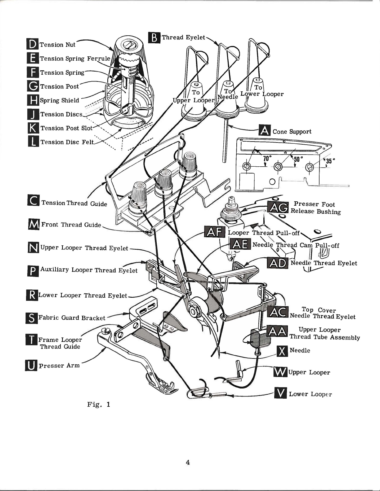
li]Tension
Nut
~
~~Thread
Eyelet
IJTension
IJTension
[!]Tension
IIJspring
OTension
(3
Tension
(I
Tension
~Front
Spring
Spring---....._~
Post~
Shield
Discs·
Post
Disc
Thread
Ferrule
~~~~
> ·--'
Slo~--
Felt--
',,_
..
Guide
lfJLower
(iJFabric
DFrame
Thread
m
Presser
Looper
Guard
Looper
Guide
Arm
Thread
Bracket
Fig.
Eyelet
1
4
........
m
Top
Needle
Upper
Thread
Upper
Lower
Cover
Thread
Looper
Tube
Looper
Loop r
Eyelet
Assembly
Page 5
NEEDLES
Each
number
size
number,
sured
number
of
all
This
is
Type
chromium
and
0
To
sample
label.
Union
denotes
in
thousandths
and
needles
machine
154
plated,
60.
have
needle,
A
complete
Selection
Thread
should
mation.
Success
of
needles
for
producing
packaged
three-quarters
Special
the
kind
stamped
size
number
packaged
uses a curved
GAS.
It
available
needle
or
type
order
of
proper
pass
in
the
under
highest
of a century.
needle
of
on
the
of
an
represent
and
is
standard
orders
and
would
needle
freely
through
operation
our
quality
has
shank,
needle
inch
sold
in
sizes
promptly
size
read:
of
brand
needles
both a type
point,
midway
by
blade
length,
shank,
the
complete
Union
needle.
length,
denotes
between
Special.
single
022, 025, 027, 029,
and
accurately
number
size
needle
Union
name~
"1000
is
Special
in
materials
should
Needles
determined
eye
number
groove,
largest
shank
symbol
Standard
grooved,
be
in
order
machines
and
and a size
finish
diameter
and
which
needle
struck
032,
filled,
forwarded.
Type
154
by
the
to
produce a good
can
which
is
workmanship
and
eye.
is
for
groove.
036,
an
Use
GAS,
size
be
secured
backed
number.
other
of
The
details.
blade,
Collectively,
given
Style
on
39500
the
spotted
040,
empty
044,049,
package.
description
Size
027".
of
thread
stitch
only
by a reputation
for
more
type
The
mea-
type
label
054,
used.
for-
by
than
MA
and
a
on
use
Release
Fig.
1)
direction
No.
21388
Again
turn
To
left,
insert
position,
nut.
Return
(AG).
After
through
eyelet.
front
Next
to
NOTE:
first
front
through
to
pressure
and
swing
until
AU,
handwheel.
replace
needle
turn
presser
thread
the
back
it
back
The
and
lower
the
back,
presser
needle
is
furnished
until
needle,
in
holder
handwheel
arm
comes
hole
of
is
threaded
then
through
looper
upper
and
third
on
presser
at
its
with
needle
leave
until
(U)
from
thread
through
thread
hole
through
CHANGING
foot
arm
(U)
lowest
machine,
is
needle
until
it
holder
to
position
THREAD
cones
eyelet
the
lower
is
from
back
the
by
out
point
at
holder
rests
is
on
(B),
the
thread
to
lower
NEEDLES
turning
of
position.
of
loosen
high
position
at
against
again
and
STAND
cone
then
upper
hole
ed
front,
hole
presser
travel.
needle
high
at
its
re-lock
support
down
hole
from
through
s e
cond
back
Turn
Using
and
position
stop
pin.
low
point
presser
(A,
through
of
tension
back
to
the
through
to
front.
foot
release
handwheel
hexagonal
clamp
withdraw
and,
Keeping
of
foot
Fig.
the
thread
front.
tension
the
nut
needle.
with
travel,
1)
front
thread
middle
bushing
in
socket
about
the
needle
then
release
it
is
hole
guide
(AG.
operatin
wrench
1/4
turn.
flat
to the
in
thi
tight
bushin
brought
of
thread
(C)
fro
guide (C),
hole
from
g
s
en
g
up
m
All
slot
(K)
threads
in
tension
then
post
continue
(G)
and
between
on
through
the tension
front
thread
discs
5
(J),
guide
through
(M).
tension
post
Page 6

THREADING
Only
Parts
It
are
will
threading
Before
direction
turning
presser
Be
tension
should
the
be
different
Thread
double
Fig.
(AF).
thread
(V)
eye
is
of
end
1)
Lead
guide
all
lower
parts
placed in
simplify
lower
beginning
until
sure
the
discs
positioned
threads
lower
of
thread
from
right
thread
(T).
the
way
looper
involved
looper
needle
foot
threads,
(J)
and
to
their
threading
to
release
in
so
as
looper
and
to
left.
behind
Turn
the
can
in
threading
relative
first,
upper
thread,
(X)
is
at
bushing
as
they
tension
the
tension
indicated
TO
thread
lead
it
Note:
fabric
handwheel
left;
then
be
threaded
positions
Style
39500
looper
swing
high
position.
(AG),
come
post
slot
post
in
Fig.
THREAD
through
through
thread
guard
in
operating
thread
easily
are
for
MA
second,
cloth
and
from
(K)
slot
1.
LOWER
right
both
must
(S)
and
through
if
shown
clarity.
to
follow
plate
open,
Release
swing
the
tension
in
tension
will
LOOPER
eyelet
eyes
of
pass
through
direction
both
tweezers
in
threading
and
pressure
presser
thread
be
at
of
front
lower
in
front
eyes
are
diagram
recommended
needle
turn
third.
handwheel
on
arm
(U)
guide
post
(G).
The
the
approximate
thread
looper
of
looper
eyelet
until
from
in
hole
heel
left
left
hand.
presser
out
(C)
tension
guide
thread
thread
of
frame
of
lower
to
(Fig.
sequence
in
operating
foot
of
position.
are
between
posts
angle
(M).
eyelet
pull-off
looper
looper
right.
1).
of
by
for
Then
(R,
Left
Thread
Turn
through
of
front
bly
tube
thread
handwheel
auxiliary
upper
oflooper
(AA),
assembly
through
CAUTION!
ing
from
Thread
handwheel
Insert
(AD),
thread
needle
under
eyelet
upper
looper
lead
tube
needle
in
operating
neck
(AC).
looper
until
looper
thread
thread
the
(AA).
upper
thread
Be
pull-
Pull
looper
sure
assembly
thread
thread
of
from
top
Thread
TO
thread
point
of
thread
eyelet
off
(AF).
under
thread
eye
upper
to
upper
TO
through
direction
right
cover
needle
THREAD
through
upper
eyelet
(N)
(P)
from
After
neck
out
of
bottom
from
looper
looper
THREAD
middle
until
to
left,
casting;
from
UPPER
left
looper
from
left
pulling
top
front
thread
eye.
THE
eyelet
needle
through
then
front.
LOOPER
eyelet
(W)
back
to
right.
up
cover
of
tube,
to
back.
is
under
NEEDLE
of
(X,
down
of
front
is
all
to
upper
casting
push
front
Fig.
both
through
thread
the
front,
NOTE:
looper
and
tube
the
needle
thread
1)
is
eyes
hole
way
then
Thread
down,
at
of
guide
left.
through
thread
down
thread
guide
its
highest
needle
in
top
(M,
Lead
both
must
tube
through
and
then
when
(M).
Then
position.
thread
cover
Fig.
thread
pass
ass
thread
insert
pass-
eyelet
needle
1).
eyes
in
em-
turn
6
Page 7

The
is
regulated
threads
formation.
amount
by
should
THREAD
of
tension
the
tension
be
only
TENSION
on
nuts
enough
needle
(D~
to
and
Fig.
secure
looper
1).
Tension
proper
threads
on
stitch
FiQ'. 2
locking
the
top
Feed
nut
(C)
surface
eccentrics
approximately
feed
39540
of
stitches
chine
eccentric
B-30.
obtainable
will
be
Generally
of
stitches
and
direction
produced;
should
or
lock
ing
pressure~
adjusting
(A).
so
that
its
of
adjusting
used
30
stitches
is
No. 39540 B-30
Minor
numbers
when
shipped
speaking~
with
differential
main
of
stretch
of
Sufficient
decrease
nut
screw
With
under
screw
in
Style
per
of
using
above
(left
material
PRESSER
presser
be
maintained.
amount
(A~
Fig.
has a right
loosening
screw
presser
surface
(B).
FEED
39500
inch.
and
the
that
is
Set
ECCENTRICS
MA
It
will
that
part
eccentric.
combination
(right
hand)
feed
being
FOOT
foot
pressure
Should
of
pressure
2)
and
turn
hand
decreases
(B)
has
been
foot
resting
approximately
cap
(D)
against
machines
be
noted
of
differential
symbol
indicate
Unless
of
eccentrics.
hand)
feed
eccentric
sewn,
or
type
PRESSURE
it
adjusting
thread
pressure.
properly
1/32
have
that
feed
approximately
otherwise
eccentric
is
selected
of
to
feed
be
necessary
on
presser
screw
so
tightening
set~
on
throat
inch
locking
been
selected
the
part
eccentric
determines
in
operation.
work
uniformly
to
increase
foot~
(B).
Adjust-
increases
When
tighten
plate~
to
1/16
nut
number
specified~
(C).
to
is
the
pressure
lock
position
inch
produce
of
also
number
number
relation
to
loosen
nut
from
main
No.
ma-
degree
Following
-5~-6,-~-~-9,-10~-11,-12,-13,-14~-15,-16,-1~-20,-2~-24,-26,-28,-30~-3~
-34,-36,-40,-50,
Additional
39540 B
Example:
with a minor
"39540
Before
chip
suggested
SETTING
should
needle
1/2
needle
needle
screw
clamp
guard,
With
center
is
inch
or
driving
(C).
screw
sequence:
THE
throat
at
above
set
stitch
eccentrics
number
-60~
-70,-100.
may
be
number
feed
Onlytwoeccentricsare
ordered
suffixed
B-30".
ASSEMBLING
assep1bling
upper
knife
and
adjusting
assembly,
AND
NEEDLE
in
high
the
arm
plate
the
position,
throat
height
assembled
front
end
needle
plate
above
(B,
Fig.
of
(A,
the
3)
in
position,
needle
point
Fig.
throat
by
loosening
Mterneedlehasbeenproperly
(C)
and
remove
throat
eccentrics
separately.
to
ADJUSTING
sewing
lower
parts,
knife
needle
slot.
should
3).
To
plate,
clamp
set
tighten
plate.
are
indicate
SEWING
remove
holder
When
be
set
align
move
available
under
No. 39540
suppliedwitheachmachine.
To
order
number
an
eccentric,
of
stitches
PARTS
cloth
assembly,
plate,
Fig.
then
3
fabric
follow
B-4
use
No.
desired.
guard,
this
~
7
Page 8

SETTING
If
needle
overlaps
moving
tightening
up
end
play
At
this
into
bar
stroke.
needle
Do
nut
not
(C).
(Fig.
have
THE
looper
looper
looper
in
point,
(B).
set
looper
5).
lower
NEEDLE
thread
thread
thread
pull-
needle
insert
With
lower
using
looper
cam
off
driving
point
looper
(Continued)
pullpull-off
pull-
off
screw,
arm.
lower
looper
1 I 8
deflecting
looper
inch
gauge
off
(B),
back.
be
sure
at
left
from
No.
needle.
(A,
Fig.
separate
When
to
(A,
Fig.
end
of
center
212 2
5-1
Tighten
4)
by
re-
take
5)
its
of
I 8 •
Now
SETTING
Now
moves
scarf
rear
to
(A,
guard
assemble
Fig.
THE
finish
the
right,
Fig.
surface
LOWER
lower
7)
differential
5
LOOPER
looper
its
point
until
the
another
(front)
possible,
looper
in
inch.
Make
needle
adjustment.
should
needle
• 00
2-.
springs
004
feed
SETTING
Set
rear
or
movement
position
Screw
sure
guard
As
be
set
inch.
dog
•
THE
needle
without
to
deflect
(B)
there
and
low
er
into
the
forward
REAR
guard
interfering
of
is
used
is
no
lower
looper
needle
from
NEEDLE
(A,
Fig.
with either
lower
needle
interference
looper.
to
knife
forward • 002-.
set
rear
Fig.
holder,
4
GUARD
6)
as
but
needle
between
high
lower
still
004
guard.
rear
as
SETTING
Fig.
THE
7
FRONT
Fig.
ing
front
to
is
g
there
needle
dog.
NEEDLE
As
6).
needle
needle
needle
used
uard.
is
GUARD
semble
When lower
without
to
After
guards
front
off
rear
guard
adjust
this
no
interference
needle guard ( C,
looper
needle
as
close
touching.
and
set
setting
and
differential
8
guard,
as
front
make
is
spring-
possible
Screw
needle
between
set
(D)
sure
feed
Fig.
6
Page 9

SETTING
THE
UPPER
LOOPER
looper
0.
004
As
the
heel
looper
Fig.
point
8
to
clearance
the
upper
of
the
head
with
Fig.
pushed
holder
Screw
shaft.
1/32
upper
shank
casting.
shaft
cross
lower
(Fig.
looper
up~er
1f64
Insert
8)
to
When
Be
9).
moves
looper
to
1/32
upper
holds
in
or
into
(C,
Fig.
Locate
1/16
the
looper
back
of
sure,
By
and
by
looper
toward
should
inch
looper
upper
out
or
turned
upper
upper
inch
looper
8)
on
beyond
looper
upper
holder
vertical
there
adjusting
turning
to
the
the
pass
clearance.
(A,
Fig.
looper
in
its
around
shaft,
clamp
looper
holds
in
holder
should
(Fig.
its
is
be
8).
holder
(Fig.
at
is a clearance
looper
the
left
top
behind
looper
of
the
of
holder
lower
its
stroke,
the
8)
in
holder,
its
shank.
if
it
the
upper
the
set
to
between
in
around
lower
its
and
is
not
so
that
8).
right
position
or
its
looper
holder.
permits
Insert
already
looper
the
end
heel
out
of
shank,
eye
Screw
upper
holder
shank
of
its
upper
of
looper
upper
with
it
looper
in
place
extends
stroke,
looper
looper
set
0.
002
(B,
to
be
in
the
and
upper
to
•
Next,
travel;
to
needle
do
it
by
For
ing
upper
of
machine;
looper
changes
slightly
turn
handwheel
check
dimensions
and
throat
moving the
example,
looper
dimension
holder
are
to
Fi
g.
left,
made,
maintain
10
until
of
plate
upper
(Fig.
looper
dimension
holder
counterclockwise
5/32
out
it
the
inch
of
may
condition
When
it
can
be
upper
upper
looper
looper
bottom
level
(Fig.
with
11).
Check
between
downstroke.
upper
looper,
slightly
counterclockwise,
machine.
Figs.
9,
looper
upper
10).
31/64
upper
be
the
checked
of
the
upper
and
Reset
10,
is
looper
If
resetting
holder
is
increased
inch
(A,
is
looper
necessary
shown
in
correct
quickly
is
moving
eye
centers
needle
top
surface
setting
to
looper
If
needle
pull
looper
rotate
looper a short
looking
to
maintain
11.
at
the
point
Fig.
increased
looking
bypulling
shaft.
to
turn
Fig.
setting
to
eye
should
of
avoid
and
needle
rubs
out
left
end
with
is
respect
necessary,
10).
by
from
left
Mter
upper
9.
is
obtained,
as
follows:
the
right,
on
the
needle,
be
upper
interference
on nee
the
back
of
its
distanc
from
left
dimensions
of
its
turn-
end
upper
these
looper
As
when
about
looper
dle
holder
end
of
e
of
of
Fig.
around
Fig. 11
9
its
shank
9
Page 10

SETTING
THE
FEED
DOGS
Now
Set
Fig.
feed
12)
dogs
plane.
sighting
straight
throat
now
plate
be
surface
tilting
pin
raises
end
of
same
time.
The
the
throat
and
differential
inch
above
assemble
the
feed
so
the
all
This
can
across
edge.
plate.
Feed
leveled
adjusting
or
both
feed
feed
dogs
plate.
throat
dogs
top
surfaces
lay
in
be
checked
teeth
Now
dogs
with
by
rotating
pin
lowers
bars
should
Screw
feed
plate.
main
(A~ B ~
the
(back)
same
with
assemble
should
throat
feed
(D).
This
the
back
at
(E)locks
dogs
of
by
a
the
be
set
so
that
knife
flush
made
knife.
knife~
width
feed
level
feed
the
Replace
dog.
at
tilting
top
(A~
with
with
Lower
so
no
of
trim
the
time
adjusting
surface
SETTING
lower
Fig.
13)
throat
hexagonal
knife
lateral
is
changed.
Fig.
the
top
pin
of
feed
THE
LOWER
knife
should
plate
head
is
spring
adjustment
12
surfaces
in
place.
dog
holder
be
set
surface.
screw
pressed
first
Now
will
rise
KNIFE
assembly.
with
Adjustments
which
against
is
necessary
appear
set
the
about
cutting
holds
above
main
3/64
Lower
edge
are
lower
upper
when
(F)
in
its
cutting
1/64
guard
slightly
edge
inch
(D)
back
After
trim~
holding
when
screw
block
upper
SETTING
Fig.
most
of
below
should
from
upper
(H)
(J)
knife
THE
13
clockwise
upper
knife
cutting
be
set
the
cutting
knife
should
in
place.
is
replaced.
STITCH
tightening
port
latch
always
tightened
(D~
position
should
edge
down
has
be
LENGTH
of
against
edge.
been
tightened
This
Lower
bracket.
pin
be
Replace
Fig.
against
extend
lower
the
set
for
to
will
knife
screw
for
the
locked
against
SETTING
upper
13)
in
upper
not
knife.
upper
proper
lock
upper
simplify
may
be
secured
(B)
and
locking
Because
cloth
with
lower
knife
position~
knife.
less
The
knife
width
plate
nut
knife
THE
than
chain
and
screw
(C)
UPPER
assembly.
setting
At
bottom
of
nut
(B)
latch
even
holder.
KNIFE
nut
knife
resetting
in
any
position
(C)
against
also
spring~
when
Clamp
(E)
of
its
serves
screw
upper
to
hold
stroke~
it
by
sup-
as
should
is
not
knife
clamp
front
feed
Length
eccentrics
of
stitch
used.
is
determined
Outer
(left)
by
the
eccentric
10
combination
(A~
Fig.
of
14)
Fig.
14
Page 11

SETTING
THE
STITCH
LENGTH
(Continued)
eccentrics.
extraction.
If
eccentrics
washer
driving
(D#
connection
SETTING
Assemble
With
arm
foot
flat
hole
edge
needle
into
to
align
on
throat
in
presser
of
needle
important
be
flat
onthethroatplate.
foot
can
be
shifting
To
Fig.
foot
clamp
move
16)
lifter
screw.
the
and
Fig.
It
may
Fig.
THE
PRESSER
the
in
sewing
needle
plate.
hole
that
the
realigned
foot
the
shaft,
clamp
lever
15
be
are
15)
(H).
presser
high
position
holes
foot
must
in
bottom
lifter
loosen
screw
shaft
necessary
unusually
from
shaft
Then
FOOT
foot
position#
and
(front
The
front
be
throat
of
If
necessary#
with
throat
lever
shaft
collar
(G)
to
the
to
tight
(E)#
continue
to
presser
swing
set
the
and
edge
aligned
plate.
the
presser
plate
(H#
and
then
left
or
actuates
(right)
(front)
In
are
facing
shaft
To
and
washer
wheel
eccentric
centric
reach
move
fitting#
it
may
as
presser
presser
back)
of
needle
with
It
is
presser
slots
Fig.
screws
shift
right
main
eccentric
feed
dog.
assembling
each
or
key.
change
(D)
in
operating
is
toward
extractor
behind
handwheel
in
be
helpful
originally
arm.
and
front
also
foot
by
16) •
(B
#
the
as
required.
(rear)
feed
(B)
feed
other.
Tighten
feed
from
nut
eccentrics#
end
direction
the
(F)#
eccentrics
back
addition
to
suggested.
Retighten
dog;
actuates
eccentrics#
Be
careful
(C)
securely.
of
shaft
front.
Using
supplied
as
shown
and
forth
to
removing
remove
Fig.
16
collar
while
the
be
not
remove
(E).
until
with
and
slightly
nut
the
inner
differential
sure
to
hubs
damage
nut
Turn
key
hand-
slot
hooked
machine#
withdraw
during
nut
(C)
(D)
and
feed
screws
(C)
in
ec-
and
and
The
foot
sure
the
lifter
presser
lever
arm
arm
does
not
(A#
bind
Fig.
and
16)
rise
and
when
the
presser
unlocked.
Adjust
than
upper
1/8
inch
adjustment
chip
guard#
until
upper
Be
With
about
horizontal
free
sure
thread
lifter
looper
motion
should
fabric
knife
machine
lever
will
be
stop
permit:
of
foot
made
guard
assembly
is
tensions
and
in
the
screw
then
lifter
with
and
cloth
reaches
STARTING
threaded
light,
middle
(C)
lock
lever
screw
plate.
its
according
set
upper
of
their
so
that
with
before
(E)
and
To
highest
TO
and
front
presser
nut
(D).
the
presser
locked
assemble
position.
OPERATE
to
threading
lower
to
looper
back
11
collar
foot
There
with
chip
diagram
locations.
(B)
foot
can
should
foot
nut
guard,
thread
secure
release
be
raised
begins
(F).
Re-assemble
(Fig.
eyelets
be
turn
the
shaft.
bushing
no
from
to
rise.
handwheel
1).
(N
higher
1/16
This
the
and
Be
is
to
R)
Page 12

STARTING
TO
OPERATE
(Continued)
Operate
forms
Swing
While
of
needle
To
Fig.
thread
thread.
ward
inch
of
1)
Set
Frame
to
its
and
increase
farther
eyelet
lower
in
its
the
stroke.
machine
moves
presser
sewing
thread
to
(AD),
looper
slot.
looper
right
slowly,
off
the
foot
on
material,
required
thread
the
rear.
so
LOWER
thread
thread
of
lower
UPPER
tongue
into
position,
NEEDLE
for
drawn
With
that
guide
looper
without
freely.
check
the
on
needle
needle
LOOPER
eyelet
(T)
heel
LOOPER
presser
insert
THREAD
needle
stitch
downstroke,
thread
(R,
Fig.
should
eyelet,
materials,
should
at
the
cam-off
THREAD
1)
be
THREAD
foot
in
place,
CONTROL
thread
position
bottom
about
set
when
control
be
drawn
of
(AE)
CONTROL
horizontal
with
lower
CONTROL
and
needle
its
its
to
make
sew
as
on
stroke,
just
eyelet
looper
sure
slowly.
follows:
needle
thread
contacts
and
all
approximately
is
About
downstroke
eyelet
position
the
the
at
the
that
way
left
chain
60%
•
(AD ,
needle
needle
for-
1/8
end
With
rest
on
top
thread
upper
increase
forwarded
wise
is a little
Position
looper
To
reduce
Prices
directed.
material
of
lower
of
thread
amount
lower
are
f.
o.
b.
A
under
slack
lower
tensions.
looper
net
cash
shipping
charge
presser
looper
looper
thread
thread
when
of
upper
POSITIONING
thread
lower
tension.
and
point.
is
made
foot,
eyelet,
looper
looper
subject
Parcel
to
set
THE
at
the
thread
TERMS
to
cover
upper
(R)
reaches
SQUARE
edge
in
change
Post
posta
looper
and
back
the
left
EDGE
is
located
the
stitch,
without
shipments
ge
and
insurance.
thread
far
enough
end
by
or
notice.
are
eyelet
so
of
its
balancing
close
insured
the
All
(N,
Fig.
upper
stroke.
needle and
edge
shipments
unless
1)
to
looper
more,
are
other-
12
Page 13

used
The
on
parts
Style
illustrated
39500
MA.
but
and
are
describ
not
used
ed be
on
Style
low
represent
39500
GS.
the
par
ls that
ar
e
Those
common
Use
in
this
Ref.
No.
1
2
3
4
5
6
parts
to
Styles
Catalog
catalog.
Part
No.
39592
39592
39524
39526
39505
39540
39540
shown
39500
No.
AR-5
AR-4
AV
AB
AB
B-30
B-30
103
m
GS
FA
phantom
and
(Style
Looper
Needle
Throat
Differential
surface---------------------------------------
Main
Main
Differential
feed
Feed
surface-----------------------------------
Feed
MA.
39500
Thread
Thread
Plate.
Dog.
Drive
views
GS)
Tension
Tension
marked
Feed
Feed
and
bearing
for
all
parts
Description
Spring--------------------
Spring--------------------
"BZ"
Dog.
marked
Eccentric-----------------------
Drive
vulcanized
"AG".
Eccentric-----------------
no
not
----------------------
vulcanized
reference
illustrated
rubber
numbers
feed
rubber
or
described
are
Amt.
Req
2
1
1
1
1
1
1
•
~1
2
13
Page 14

Helpful,
c
icnt
machine sewed
Sales
esting,
obligation
authoritative
types
of
Promotion
illustrated
are the
information
equipment
article
is
available
Department.
bulletins
following:
for
making
from
Among
that
are available
on
the
virtually
Union
the
many
most
effi·
Special's
inter-
without
any
HERE
ARE
HELPFUL
No.
240,
"Men's,
No.
249,
"Rainwear"
No.
250,
"Men's
No.
251,
"Service
No.
252,
"Men's
No.
253,
"Overalls, Coveralls, and Dungarees"
No.
254,
"Men's
No.
256,
"Knit
No.
259,
"Men's
No.
260,
"Work
No.
262,
"Cotton,
Bags"
No.
263,
"Men's
No.
264,
"Men's
No.
265,
"Women's
No.
266,
"Women's
No.
267,
"Corsets, Girdles, Brassieres"
No.
268,
"Children's
No.
269,
"Mattresses,
Upholstery"
No.
271,
"Awnings,
No.
273,
"Curtains & Drapes"
No.
610,
"Kiipp-it"
No.
710,
"MCS
No.
730,
"MCS
Hemmer"
No. 740,
No.
No.
No.
"Columbia
i
ng
No.
"MCS
750, " Fusing Presses"
1100,
"Lewis
stitch,
1105,
"Button
1500,
Blindstitch,
"Alteration
Machines"
Women's,
Dress
Shirts"
Shirts
and
Shorts
Outerwear"
Sports
Gloves"
Clothing"
Women's,
ForMation
Automatic
Automatic
Machines"
and Pajamas"
Knit
Underwear"
Shirts"
Burlap,
Wear"
Wear
And
Wear"
Slip
Canopies, Tents,
Blindstitch,
Sewers- T i
Saddle
Department
Children's
Pants"
Jute,
and
Children's
High Fashi
Covers,
Unit"
Dual
Underfront
Rib-Knit
Chainstitch,
cket
Stitch,
Footwear"
Multiwall
Jackets"
on"
Furniture
Tarps"
Cuff
Machine"
Lock·
Tackers"
and
Tie
Machines"
Paper
Shirt
Clos·
BULLETINS
TO
SEWING
HELP
YOU
PROBLEMS
and
CATALOGS
SOLVE
®
Page 15

BOOST
PRODUCTION
WITH
WORK
UNION
THESE
AIDS
SPECIAL
FROM
PNEUMATIC
convenlional Class
sci
ssor-aclion
positi
ve cui.
AIR
FABRIC
signed
to
remove curls from top and
knit materials as fabric passes
area.
Style
CHAIN·CUTTER-Io
mechanism
Style
lor
Class
2899
B-1
39500
and
2899
A-1
UNCURLER-
39500
machines, uses air
that
bottom
r use on
39600
is
a durable
makes a clean
This
unit, de-
plies of flat
through
jets
sewing
PNEUMATIC
operated
machines
simply by knee-touch ing an actuating swit
CHAIN
small pneumatic chain cutter
lor
instalialion as an accessory unit on Class
36200
Flatseamers. Sty le 2899A-6
FOOT
loot
lifter
allows
CUTTER-
lor
the operator to raise the
The above photo
LI"ER-The
use
on
that
Class
shows
is
ava
air-
39500
loot
ch.
the
ilable
KNIFE
GRINDER
type knives, is simple and easy
nates defecti
sharpens
ve
garments caused by
straight
to
operate, elimi-
dull
or
®
u
fi
NEST
QUALITY
MAcH
IN
E
wheel
insuring
ELECTRONIC
to
move the needle up
better
NEEDLE
control,
uniform quality and increased
POSITIONERS
or
down
•••
AMCO
angle
knives.
this
allows the oper
HEAT
DISPELLER-Union
unit (arrow) is an effective means
oil temperature where heavy duty servi
qu
ores
it
. Style
2899
E-1
eliminate
the
productio
necessity
ator
to
keep both hands on the wo rk,
n.
Special's auxiliary
of
reaching
lor
for
the ha
reducing
ce
re-
nd-
Page 16

.,.o
..
...
'
Q
WORLD'S
,..,lf
FINES
T
,,
QU
ALITY
"'
*
INDUSTRIAL
SEWING
MACHINES
UNION
SPECIAL
maintains sales
and
facilities throughout the world. These offices
aid
you
in
the selection of the right sewing
equipment for your particular operation. Union
Special representatives
tory trained
promptly
tion, there
serve you.
ATLANTA,
BOSTON,
CHICAGO,
DALLAS,
LOS ANGELES, CAL.
NEW
PHILADELPHIA,
GA.
MASS.
TEXAS
YORK, N.
and
is
Check with
ILL.
Y.
PA.
and
a Union Special Representative to
efficiently. Whatever your loca-
are
and
service men
able
to serve your needs
him
today.
MONTREAL, CANADA
TORONTO, CANADA
BRUSSELS, BELGIUM
LEICESTER,
LONDON,
PARIS, FRANCE
STUnGART,
service
will
are
fac-
ENGLAND
ENGLAND
GERMANY
400
Representatives
MACHINE
N.
FRANKLIN
industrial
and distributors
cities
throughout the
COMPANY
ST.,
in
all
important
world.
CHICAGO,
ILL.
60610
 Loading...