

Page 1
®
INDUSTRIAL
SEWING
FINES,T
STYLE
39500
QUALITY
JR
LEWIS
•
COLUMBIA
tf
.
..
MACHINES
~
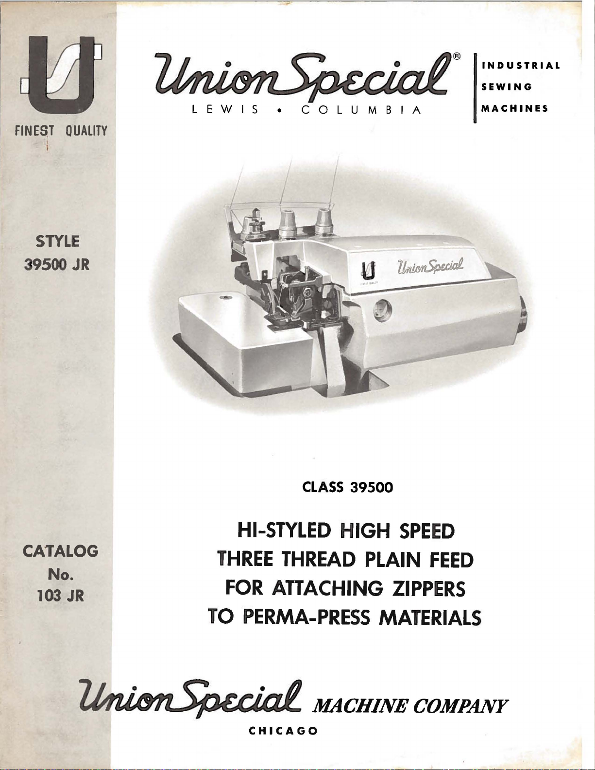
CLASS
HI-STYLED
CATALOG
No.
103
JR
THREE
FOR
TO
PERMA-PRESS
CHICAGO
THREAD
ATTACHING
39500
HIGH
SPEED
PLAIN
FEED
ZIPPERS
MATERIALS
Page 2
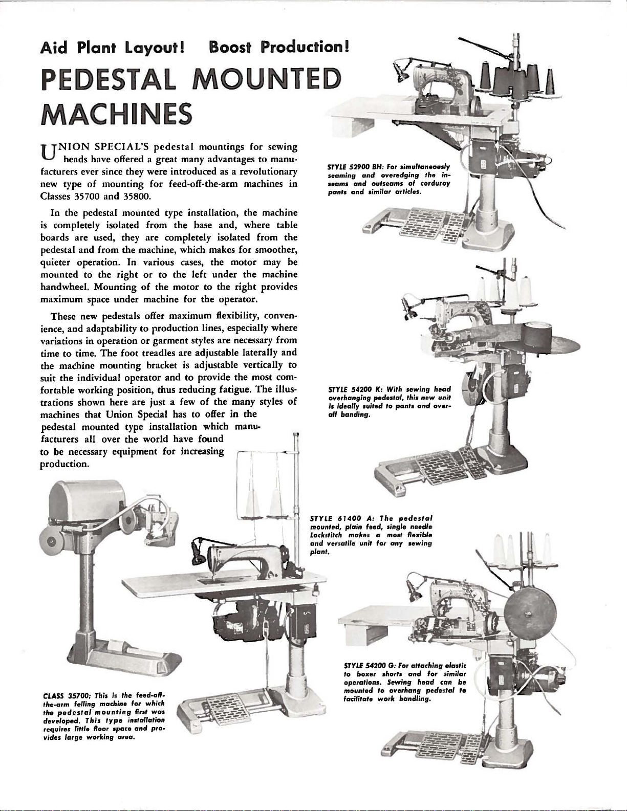
Aid
Plant Layout!
Boost Production!
PEDESTAL
MOUNTED
MACHINES
UNION
heads have offered a great many advantages
facturers ever since they were introduced as a revolutionary
new type
Classes 35700 and 35800.
In the pedestal mounted type installation, the machine
is
completely isolated from the base and, where table
boards are used, they are completely isolated from the
pedestal and from the machine, which makes for smoother,
quieter operation. In various cases, the motor may be
mounted to the
handwheel. Mounting
maximum space under machine for the operator.
These new pedestals offer maximum flexibility,
ience,
variations in operation
to
time
the machine mounting bracket is adjustable vertically to
suit the individual operator and
fortable working position, thus reducing fatigue.
trations shown here are just a few
machines that
pedestal mounted type installation which
facturers all over the world have found
to
be necessary equipment for increasing
production.
of
and
adaptability
time.
SPECIAL'S
pedestal
mountings for sewing
to
mounting for feed-off-the-arm machines
right
or
to the left under the machine
of
the
motor
to
production lines, especially where
or
garment styles are necessary from
The
foot treadles are adjustable laterally
to the
to
provide the most com-
right
providt>s
The
of
the many styles
Union
Special has
to
offer
in
the
manu-
r-
1
I
manu-
in
conven-
and
illus-
of
STYlE
52900
seaming
seams
pants
STYLE
overhanging
is ideally
all
and
and
and
54200
banding.
SH
: For simultaneously
overedging
outseams
similar articles.
K:
With
pedestal,
suited
to
pants
the
corduroy
head
and
over·
in-
of
sewing
this new unit
CLASS
35700:
the-arm
the
pedestal
developed.
requires
vides
large
This
is
the
type
space
feed-off-
first
installation
and
area.
was
pro-
felling machine for which
mounting
This
little floor
working
STYLE 6 J
mounted, plain feed, single
Locbtitch
and
plant.
400
A:
make
versatile unit for
s a most flexible
STYLE
54200
to
boxer
operations.
mounted
facilitate work handling.
The
any
G: For
shorts
Sewing
to
overhang
pedestal
needle
sewing
attaching
and
head
elastic
for
similar
can
pedestal
be
to
Page 3
Catalo
g
No
.
103
JR
(Supplement
ADJUSTING
to
Catalog
INSTRUCTIONS
FOR
AND
LIST
CLASS
OF
Style
39500
PARTS
39500
JR
No.
OPERATING
103
FJ)
January,
1968
F
irst
Copyri
E
dition
g
ht
1968
By
Union
Rights
Special
Reserved
Machine
in
All
MACHINE COMPANY
INDUSTRIAL
Printed
SEWING
CHICAGO
in
MACHINES
U.S.A.
Co.
Countrie
s
3
Page 4
IDENTIFICATION
OF
MACHINE
Each
the
machine.
numbers
"Style
changes
ber.
39500
are
Example: "Style
Styles
which
differs
39500".
This
junction
F J
are
therewith.
illustrated
illustration
and
the
number
numbers
ference
ber
numbers
listed
This
in.
It
can
39500.
from
References
the
handwheel
Union
Special
Style
have
one
JR".
made
of
machines
from
catalog
will
only~
in
and
the
catalog
also
be
operator's
is
away
machine
numbers
or
more
Special
are
letters
Style
in a standard
39500
similar
the
Style
number
APPLICATION
is a supplement
Only
and
be
found a listing
of
pieces
merely
should
second
applies
applied
to
those
listed
at
required.
indicate
never
column.
specifically
with
directions~
position
from
operator.
is
identified
classified
suffixed~
numbers
machine~
JRZ".
in
construction
in
that
to
Catalog
parts
the
of
used
back
the
parts~
Numbers
the
position
be
used
discretion
while
to
such
seated
in
the
to
as
by a Style
as
standard
but
never
contain
a
"Z"
is
are
it
contains
OF
CATALOG
No.
on
Style
of
this
with
of
ordering
standard
some
right~
at
the
contain
the
suffixed
grouped
103
FJ
39500
catalog.
their
in
the
that
parts.
Style
Special
left~
machine.
number
and
special.
the
letter
to
"Z".
the
under a Class
no
letters.
and
should
JR~
but
On
part
first
part
column
in
Always
of
machine
Styles
front~
back~
Operating
on a name
Standard
letter
''Z''.
When
standard
only
Style
Example:
be
used
not
on
Style
the
page
numbers~
opposite
description
are
the
illustration.
use
the
part
as
listed
of
machines
etc.,
direction
plate
on
Style
Example:
minor
num-
number~
"Class
in
con-
39500
the
reference
Re•
num-
here-
in
Class
are
given
of
Hi-StyledHigh
seaming
Knife,
39500
Machine.
Automatic
JR
flies
and
or
and
similar
SSj-1.
Medium
adjusted
CAUTION!
filled
straight
should
before
mineral
be
used.
Machine
gauge
lines
on
front
when
machine
Machine
main
reservoir
SpeedSingle
Plain
Lubricating
to
heavy
zipper
tapes
operation
Standard
feed.
Maximum
Oil
was
beginning to
oil
of a Saybolt
is
filled
of
with
machine.
is
is
automatically
filled.
STYLE
Curved
Feed,
System.
duty
to
pants
of
Perma-Press
seam
width
recommended
drained
operate.
oil
at
spring
Red
stationary.
lubricated.
Check
oil
Blade
Trimming
machine
fronts;
3/16
from
Oil
viscosity
bulb
on
daily
OF
MACHINE
Needle~
Mechanism
for
also
material.
inch.
OILING
machine
capacity
of
cap
in
oil
level
No
before
Two
Looper,
simultaneously
attaching
Seam
speed
when
200
top
cover.
Stitch
of
to
range 6 to
6500
shipped,
Class
250
indicator
oiling
the
is
necessary~
morning
with
Spring
zippers
Specification
R.
P.M.
so
39500
seconds
Oil
level
should
start;
Three
Pressed
attaching
to
right
16
per
reservoir
is
si:'&
at
100
is
checked
show
between
other
add
oil
Thread
right
flies
504-SSa-1
inch;
must
ounces.
Fahrenheit
at
than
keeping
as
required.
Over•
Lower
pants
only
cam
be
A
sight
gauge
The
oil
It
is a magnetic
have
entered
drain
plug screw
screw
the
crank
is
designed
case.
located
to
accumulate
It
should
at
be
back
4
of
machine
possible
removed
and
near
foreign
cleaned
bottom
edge
materials
periodically.
of
which
base.
may
Page 5
NEEDLES
Each
denotes
number,
ed
in
thousandths
size
les
number
packaged
Class
needle
available
Type
154
No.
GAS
To
sample
on
label.
Selection
should
Success
of
needles
putation
more
than
Union
the
kind
stamped
represent
and
39500
for
Style
of
the
Round
groove,
sizes
have
needle
needle,
A
complete
of
pass
freely
in
the
packaged
for
producing
three-quarters
Special
of
shank,
on
of
sold
machines
39500
the
an
needle
point,
needle
inch,
the
complete
by
Union
use a curved
JR
is
recommended
shank,
struck
022, 025,
orders
or
the
type
order
proper
needle
through
operation
under
highest
of a century.
has
length,
shank,
midway
Special.
Type
needle.
round
groove,
027,
promptly
and
size
would
size
needle
of
Union
our
brand
quality
both
between
symbol
154
De
point,
spotted,
029,
and
number
read:
is
determined
eye
in
Special
name,
type
groove,
denotes
blade
GAS.
scription
and
finish
largest
shank
which
needle.
Below
curved
chromium
size
and
is
and
blade,
number.
and
diameter
eye.
given
The
is
the
Sizes
plated
other
on
standard
standard
032, 036, 040, 044, 049,
accurately
should
"1000
order
~
needles
Needles,
to
machines
in
filled,
be
forwarded.
by
size
produce
can
materials
Type
of
a g
be
which
The
type
details.
of
blade,
Collectively,
the
label
recommended
description
length,
and
is
054.
an
empty
Use
154
GAS,
thread
ood
used.
stitch
secured
is
backed
and
workmanship
number
The
size
measur-
type
and
of
all
need-
and
sizes
single
available
package,
description
Size
032".
Thread
formation.
only
by
use
by a re•
for
in
a
CHANGING
Release
Fig.
1)
direction
No.
21388
Again
turn
To
left,
insert
position,
nut.
Return
replace
pressure
and
swing
until
AU,
handwheel
needle
turn
presser
on
presser
needle
is
furnished
until
needle,
in
holder
handwheel
arm
presser
at
its
with
needle
leave
until
(U)
arm
lowest
needle
until
holder
to
foot
(U)
out
point
machine,
is
at
holder
it
rests
is
position;
THREAD
After
through
eyelet.
front
•
that
the
through
and
third
tension
front
thread
back
Next
to
back
lower
the
through
discs
thread
hole
it
is
and
looper
upper
(J),
guide
comes
of
thread
threaded
then
through
thread
hole
the
lower
through
(M).
from
back
cones
eyelet
through
the
is
threaded
to
front,
hole
back
tension
on
(B),
the
lower
to
post
NEEDLES
by
turning
of
of
loosen
high
ag
again
re-lock
cone
then
upper
holes
through
second
front.
slot
presser
position.
travel.
needle
position;
at
high
ainst
at
its
presser
STAND
support
down
holes
from
the
through
All
(K)
in
Turn
Using
withdraw
position
stop
pin.
low
(A,
through
of
tension
back
tension
the
threads
tension
foot
handwheel
hexagonal
clamp
and,
point
foot
Fig.
the
to
front.
thread
middle
then
post
release
nut
needle.
with
Keeping
of
travel;
release
1),
front
thread
It
guide
hole
continue
(G)
bushing
in
socket
about
the
needle
then
bushing
it
is
hole
guide
should
front
between
and
operatin
wrench
1/4
turn.
flat
to
in
tighten
(AG).
brought
of
thread
(C)
from
be
noted
(C),
first
to
back
on
through
(AG,
g
the
this
up
the
5
Page 6

li]
Tension
IJ
Tension
II
Tension
[!]
Tension
IIJ
spring
O Tension Discs -c
13
Tension
II
Tension Disc
Nut
Spring
Spring--../
Post
----
Shield
Post
Slo~
Felt
Ferrule
,.
:;
:
-
.
--..
·· ..
~
~
'.:~~~
~
1
;
J1:l,
~
m
~
~
Thread
Eyelet
fiJ
Front
im
upp
m Lower Looper
m
Fabr
D
Fram
Thread Guide
ID
Pr
Thread
er Looper
ic Guard
e Looper
esser
Arm
Guide
Thread Eyelet
Thr
ead E
yelet
Bra
cket
~)
~~~~
~
1J11~
..
u.;:iill
Top
Needle Thr
Thread Tube Assembly
Cover
ead Eyelet
Upper Looper
Fig
. 1
6
Page 7

THREADING
Only
are
placed
It
will
threading
Before
direction
turning
Be
sure
tension
Double
(R. Fig.
off
(AF).
looper
looper
Left
thread
(V)
eye
Turn
through
of
upper
of
looper
(AA)..
lead
sembly
throu
gh
parts
in
their
simplify
lower
beginning
until
presser
threads,
discs
(J)
end
1)
from
Lead
guide
is
all
of
lower
handwheel
auxiliary
looper
thread
thread
(AA).
upper
Pull
looper
involved
relative
threading
looper
to
needle
foot
release
and
in
of
thread
right
thread
(T).
the
way
looper
until
looper
thread
pull-off
under
thread
eye
in
threading
first,
thread,
(X)
is
as
they
diagonal
TO
and
to
left.
behind
Turn
to
can
TO
point
thread
eyelet
(AF).
neck
out
from
positions
this
upper
swing
at
high
bushing
come
slots
THREAD
lead
Note:
fabric
handwheel
the
left;
be
threaded
THREAD
of
upper
eyelet
(N)
from
After
of
top
bottom
front
are
for
machine
looper
position,
(AG);
from
it
through
thread
then
cover
of
to
shown
clarity.
second,
cloth
plate
and
the
(K)
in
LOWER
must
guard
in
thread
easily
UPPER
looper
(P)from
left
to
pulling
casting
tube
back.
in
threading
to
follow
open,
release
swing
tension
tension
LOOPER
both
eyes
pass
(S)
and
operating
through
if
tweezers
LOOPER
(W)
back
right.
up
upper
and
and
push
and
presser
thread
posts
of
in
through
is
all
to
front,
Note:
looper
down
tube
diagram
recommended
needle
turn
third.
handwheel
pressure
arm
guide
(G).
lower
front
looper
of
looper
eyelet
direction
both
are
the
eyes
way
until
in
left.
then
thread
must
thread
through
down;
(Fig.
on
presser
(U)
out
(C),
thread
hole
heel
from
left
hand.
through
pass
tube
thread
then
insert
1 ).
sequence
in
operating
foot
of
position.
are
between
eyelet
thread
of
frame
of
lower
left
to
Lead
thread
both
in
assembly
tube
thread
Parts
by
pull-
r ig
ht.
eyes
front
as-
of
CAUTION!
passing
from
Turn
position.
eyelet
needle
(AD),
thread
The
regulatedby
on
threads
formation.
Sufficient
should
be
decrease
nut
(A,
screw
sure,
has a right
loosening
properly
locking
the
top
nut
surface
Be sure
tube ass
handwheel
Insert
needle thread
under
eyelet
THREAD
amount
of
three
should
PRESSER
presser
maintained.
amount
Fig.
2)
decreases
set,
tighten
(C)
so
that
of
embly
in
operating
neck
(AC).
tension
knurled
be
only
FOOT
foot
Should
of
pressure
and
turn
hand
thread
lock
its
adjusting
upper
to
upper
TO
from
of
top
cover
Thread
TENSION
on
needle
tension
enough
PRESSURE
pressure
it
be
on
adjusting
so
pressure.
nut
(A).
under
surface
screw
looper
THREAD
direction
nuts
to
necessary
presser
thread
looper
right
castin
needle
and
(D,
secure
to
feed
screw
is
eye.
THE
to
looper
until
left,
g;
from
Fig.
NEEDLE
needle
throu
then
front.
threads
1).
proper stitch
work
to
increase
foot,
loosen
(B).
uniformly
tightening increases
With
(B).
When
presser
is
pressure
foot
approximately
Set
cap
(D)
under
lower
(X.
gh
both
down
through
is
Tension
or
lock
Adjusting
pres-
adjusting
resting
1 I 32
against
looper
Fig.
eyes
screw
on
throat
inch
locking
1)
of
hole
to
nut
is
at
needle
Fig.
(B)
plate,
1 I
16
(C).
thread
its
in
top
2
has been
position
inch
when
highest
thread
cover
from
7
Page 8

The
imately
entric
dicates
Unless
the
numh~r
feed
12
on
eccentric
stitches
Style
39500
approximately
otherwise
of
stitches
used
per
inch.
JR
is
the
specified#
as
outlined
FEED
in
this
It
No.
39540
number
machine
machine
will
of
above.
ECCENTRICS
has
be
noted
B-12.
stitches
will
be
that
Minor
produced
shipped
been
the
selected
part
number
when
with
the
to
number
of
the
using
eccentric
produce
of
the
part
symbol
that
to
approx-
feed
ecc-
in-
eccentric.
produce
Following
-6~
-7~
-8~
-36~
-40.
may
be
number
Before
chip
guard,
suggested
With
should
needle
1/2
needle
needle
screw
inch
If
needle
center
is
or
driving
{C).
separate
screw,
..
9~-10#
Only
ordered
suffixed
assembling
upper
sequence:
SETTING
throat
at
high
above
set
the
Remove
by
moving
be
sure
stitch
-11#
one
separately.
to
knife
plate
in
the
position,
throat
height
arm
thread
to
take
number
-12,13#
eccentric
feed
-14~
is
To
indicate
number
ASSEMBLING
and
adjusting
assembly,
THE
NEEDLE
assembled
front
end
of
needle
plate
above
{B,
throat
cam
looper
up
Fig.
plate.
pull-off
thread
end
{A~
the
3)
play
eccentrics
-15#
...
supplied
order
of
AND
sewing
lower
in
position,
needle
point
Fig.
should
3).
throat
by
loosening
(A,
Fig.
pull-off
in
needle
are
available
16
..
-18~
-20,
with
each
an
eccentric~
stitches
desired.
ADJUSTING
parts,
knife
remove
holder
needle
slot.
plate,
To
When
be
set
align
move
clamp
4)
overlaps
back.
When
driving
under
-22~
-24,-26,
machine.
use
No.
Example:
SEWING
cloth
assembly,
looper
retightening
arm.
No.
39540
-28
..
-30,-32,
Additional
B-4,
·34,
eccentrics
39540 B with a minor
"39540
B-12".
PARTS
plate,
thread
then
Fig.
looper
fabric
follow
3
pull-off
guard~
this
{B),
pull•off
-5~
Screw
between
Fig.
(B)
rear
is
4
used
needle
to
guard
set
rear
and
At
this
into
bar
stroke,
needle
Do
not
nut
have
{C).
Now
set
{Fig.
assemble
SETTING
Set
rear
possible~
per
or
movement
position
needle
lower
to
guard.
looper.
8
point,
{B).
looper
5),
lower
needle
without
deflect
insert
With
lower
point
using
looper
the
THE
guard
interfering
of
lower
needle
Make
lower
looper
1 I 8
looper
gauge
deflecting
main
REAR
feed
NEEDLE
{A..
with
knife
forward . 002-.
sure
there
looper
at
left
inch
from
No.
needle.
dog.
GUARD
Fig.
6)
either
holder~
is
no
interference
{A~
Fig.
end
of
center
21225-1/8.
Tighten
as
high
lower
but
004
loo-
still
inch.
5)
its
of
as
in
Page 9

SETTING
THE
LOWER
LOOPER
Now
looper
into
the
springs
.
002-.
SETTING
Assemble
lower
set
front
without
set
front
sure
there
and
main
finish
moves
needle
forward
004
inch.
looper
needle
touching.
needle
is
feed
lower
to
the
scarf
from
THE
front
is
FRONT
needle
springing
guard
Screw
guard.
no
interference
dog.
looper
right,
(A,
rear
as
close
its
upper
mits
ed
looper
if
(C,
looper
upper
shank
holder
adjustments.
its
point
Fig.
7)
guard
NEEDLE
guard
(C,
needle
as
possible
(D)
is
used
After
this
between
SETTING
Insert
holder.
looper
it
to
be
around
holder
it
is
not
Fig.
8)
holder
looper
extends
(Fig.
should
until
surface
GUARD
Fig.
off
back
to
setting
needle
THE
upper
Screw
in
pushed
its
intoupper
already
on
clamp
in
1 I
8).
As
the
another
6).
to
adjust
guards
UPPER
looper
(B,
its
holder,
in
shank.
in
in
the
its
holder
16
to
lower
be
set
needle
When
guard,
needle
and
make
(A,
Fig.
or
out,
Insert
looper
place.
holds
shaft.
3 I 32
LOOPER
Fig.
8)
and
or
8)
holds
per-
turn
upper
shaft,
Screw
the
upper
Locate
so
that
inch
beyond
in
e
the
Fig.
5
As
the
heel
looper
Next,
travel;
needle
do
it
10
represents
Fig.
the
head
check
and
by
6
upper
of
the
with
turn
dimensions
throat
moving
looper
up_per
1/32
looper
to
handwheel
plate
the
the
(Fig. 1 0).
upper
dimensional
When
right
holder
looper
(Fig.
looper
of
upper
shank,
left
of
(Fig.
moves
1116
until
of
upper
looper
end
should
shank
8).
and
looper
set
the
9)
toward
should
inch
looper
holder
setting
the
upper
of
its
stroke,
be
slightly
Be
sure,
the
casting.
shaft
upper
lower
the
pass
clearance.
is
at
looper
If
resetting
(A,
looper
set
to
looper
looper
top
behind
the
point
Fig.
for
Style
upper
position
back
there
By
and
point
eye
of
left
with
is
10).
is
at
the
looper
upper
of
vertical
is a clearance
adjusting
by
turning
to
cross
its
the
end
respect
with
stroke,
lower
of
its
to
. 002
necessary,
Figure
39500
JR.
looper
the
looper
lower
to
Fig.
between
holder
around
looper
. 004
7
heel
in
or
out
its
to
the
clearance
of
9
Fig.
8
Page 10

SETTING
THE
UPPER
LOOPER
(Continued)
NOTE:
point
at
left
upper
9/64
shaft.
around
the
needle.
downstroke.
slightly
of
machine.
12).
throat
pin
appear
adjusting
point
should
feed
The
and
31 I 64
end
looper
inch
After
its
When
upper
Check
Assemble
raises
The
Main
plate
of
be
dog
the
the
and
feed
above
travel,
teeth
dimensions
of
its
holder
is
increased
these
shank
correct
looper
eyes
setting
If
rotate
Reset
SETTING
chaining
feed
by
or
lowers
dogs
the
pin
in
3/64
inch
(B)
are
inch
rotating
from
travel.
counterclockwise.
by
pullingupper
changes
slightly
is
of
to
needle
looper a short
to
dog should
should
throat
place.
the
top
above
flush
to
setting
moving
the
avoid
rubs
maintain
THE
feed
feed
the
back
be
plate.
With
of
the
the
with
9/64
top
For
are
maintain
is
to
upper
interference
the
FEED
dog
be
set
throat
the
inch
of
throat
example.
made,
obtained,
the
right
looper
back
distance
dimensions
DOGS
to
main
levelled
tilting
end
of
level
Screw
the
feed
teeth
top
from
plate
dimension
looking
looper
it
the
condition
it
and
and
between
of
upper
feed
with
adjusting
the
feed
at
the
(D)
dogs
on
the
plate.
of
the
throat
center
to
upper
from
holder
may
can
the
needle
looper.
counterclockwise,
of
Figs.
dog
respect
pin
bar.
time
locks
at
their highest
main
Now
line
looper
31/64
left
end
to
the
be
necessary
shown
be
checked
upper
upper
(A,
(C).
teeth
feed
feed dog (A)
set
plate.
in
looper
should
looper
pull
9, 10,
B, Fig.
to
the
Thi
fir st
tiltin
chain
ing
of
needle
is
of
left.
Fig.
quickly
align
looper
11.
s
g
to
point.
increased
machine;
out
of
to
turn
9.
as
eye
exactly
and
needle
out
looking
upper
when
by
dimension
upper
upper
follows:
centers
(Fi
on
of
its
from
looper
looper
turning
looper
looper
on
g. 11 ).
needle
holder
left
is
As
the
end
pin
with
Fi
g.
10
for the
nut
(C)
cloth
even
SETTING
bly.
be
set
plate
with
lower
pressed
lateral
width
Lower
position
locking
Be cause s
plate
when screw
latch spring,
Replace
Lower
with
surface.
hexagonal
knife.
against
adjustment
of
trim
knife
by
nut
cr
is
not
THE
lower
knife
cutting
Adjustments
head
Lower
is
tightenin
(C)
again
ew (B)
it
should
tighten
LOWER
knife
(A,
edge
screw
knife
upper
is
necessary
changed.
may
be
g s
st s
also
always
ed agains t
holder
Fi
g.
flu
sh
which
knife,
sec
ured
crew
upport
ser
ves
KNIFE
assem-
13)
should
with
throat
are
made
holds
is
sprin
so
no
when
in
any
(B)
and
bracket.
as
latch
be
lock
ed
lower knife
g
holder.
Fi
g. 9
Fig.
11
10
Page 11

SETTING
THE
UPPER
KNIFE
be
tightened
ting
when
Length
entric
the
B
sure
edge
the
over the
to
used
feed
...
12.
In
assembling
the
of
left side,
dama
Fig.
to
lock
upper
SETTING
of
stitch
in
machine.
eccentric
hub
and
feed
ge
hub
shaft
eccentric
so
on
12
upper
knife
the
the
or
is
THE
STITCH
is
for
Style
the
feed
oil groove
spacer
undercut
feed
key.
knife
replaced.
determined
Note
eccentric
eccentric.
holding
LENGTH
that
39500
is
to
(B)
on
by
the
JR
(A,
the
should
the
block
the
part
number
is
No.
Fig.
left.
spacer
Be
careful
Clamp
position,
(F)
against
stroke,
knife
inch
The
against
back
proper
(J)
feed
39540
14),
Beveled
also
will
Replace
After
in
ecc-
of
be
be
to
be
not
upper
in
its
upper
should
below
chain
the
from
width
place.
setting
most
front
extend
cutting
guard
upper
the
upper
of
This
upper
knife
nut
knife.
cutting
(G)
cutting
knife
trim,
will
knife
(D,
Fig.
(E)
to
clockwise
At
bottom
edge
not
less
edge
of
lower
should
knife
be
and
edge.
has
been
screw
simplify
assembly.
13)
hold
clamp
position
of
of
upper
than
1 I
knife.
set
down
slightly
set
(H)
should
reset-
in
its
64
for
Tighten
To
washer
wheel
entric
extractor
eccentric
be
necessary
slightly
Assemble
presser
and
back)
be
aligned
the
bottom
can
be
15).
a
collar
nd
To
then
nut
(C)
securely.
change
(D)
and
in
operating direction
is
toward the fr
(E),
as
during extraction.
arm
and
reali
move the shaf
shift the
screws
feed eccentrics,
feed eccentric
suppli
shown and
to
move
the pres
into sewi
flat
on
throat
with
front
of
the
presser
gned wi
th
foot lifter l e
and
clamp screw.
ed
throat plate s
ont.
with
withdraw
handwheel
SETTING
ser
foot
ng
position
plat
ed
ge
foot
t,
loosen
remove
spacer
until
Using
machine,
eccentric.
to
presser
and
e.
The fr
of needle
be
flat
lots by shifting the
coll
ver
sha
(B).
key
slot
hooked
reach
back
THE
set
ont edge
hol
e in
on the
ar
scr
ft
to the left
nut
Turn
PRESSER
the
hand
in
ecc-
eccentric
behind
It
may
and
forth
arm.
pre
sser foot
thro
thro
at p
ews (B,
With
(C),
of
at
or
...
FOOT
needle
needle
plate.
late.
foot
Fig.
r i
to
alig
hole
It
If
necessary,
lifter
15)
ght
as
Fi
in high
n needle hol
in
presser
is
also
lever
and
clamp screw
required.
g. 13
position, swin
es (fr
foot
must
important
presser foot
shaft
(H,
Fig
Retight
g
ont
that
.
(G)
en
11
Page 12

SETTING
The
(B)
secure
bind
locked.
and
foot
rise
lifter
the
THE
shaft.
when
PRESSER
lever
arm
Be
presser
sure
foot
FOOT
(A.
Fig.
the
release
(Continued)
15)
and
presser
bushing
arm
the
does
collar
not
is
un-
without
freely.
While
needle
be
just
if
excessive
tion
needle
contacts
Fig.
presser
Swing
sewing
thread
tight
thread
needle
14
foot
presser
on
is
drawn
enough
thread
thread.
in
place,
material,
on
to
feed
is
pulled
eyelet
then
foot
guard,
its
thread
foot
needle
(AD.
Adjust
can
be
lock
inch
screw
guard.
diagram
of
free
begins
(E)
highest
Be
eyelets
their
to
make
into
position.
NEEDLE
check
down
chain
on
off
the
Fig.
lifter
raised
the
motion
to
and
fabric
turn
handwheel
position.
sure
(Fig.
front
sure
THREAD
needle
stroke.
stitch
up
stroke.
1)
lever
no
higher
nut
(D).
of
rise.
locked
guard
STARTING
machine
1).
(Nand
to
so
This
With
back
that
insert
CONTROL
thread
At
tongue.
With
that
needle
chain
stop
screw
than
There
foot
lifter
adjustment
with
nut
and
cloth
until
is
R)
locations.
material.
upper
TO
threaded
thread
about
forms
control
top
of
Stitch
needle
thread
(C)
upper
should
lever
(F).
OPERATE
horizontal
needle
Re-assemble
plate.
knife
according
tensions
Operate
and
and
sew
as
follows:
stroke,
tends
at
bottom
cam
so
that
looper
be
from
before
should
To
assembly
light.
and
machine
moves
slowly.
to
pull
of
pull-off
presser
will
permit;
1/16
the
presser
be
made
the
assemble
reaches
to
threading
set
in
the
off
the
Usually
thread
down
stroke,
slightly
(AE)
foot
to
1/8
with
chip
chip
looper
middle
slowly,
tongue
all
should
posi-
just
It
pull-off
a
tor)
needle
LOWER
With
looper
so
thread
pull-off
tion.
1/8
inch
pull-off
should
inch
to
the
time
its
travel.
is
desirable
eyelet
to
delay.
thread.
material
thread
is a little
(AF)
Looper
distance
(AE).
be
set
right
lower
to
adjust
well-forward
slightly,
LOOPER
under
eyelet
reaches
thread
with
of
slack
behind
Frame
its
lower
looper
(R.
its
pull-off
eyelet
looper
the
(toward
the
THREAD
presser
Fig.
looper
is
1)
when
most
(AF)
needle
approximately
(V)
at
extreme
needle
the
tightening
CONTROL
foot.
back
looper
rearward
thread
is
thread
heel
set
far
set
guide
eyelet
left
thread
operof
the
lower
enough
thread
posi•
about
cam
(T)
1/8
at
end
of
12
Fi
g.
15
Page 13

LOWER
LOOPER
THREAD
CONTROL
(Continued)
While
portion
looper
the
tension
eyelet
Before
three
will
draw
is
pull-off
Fig.
to
all
that
to
edge.
tensions
not
During
upper
drawn,
To
1)
have
If
end
it
form
sewing
of
lower
thread
while
(R) down,
proceeding
markedly
needle
looper
upper
reaches
move
should
slightly
it
becomes
play
is
in
higher
near
on
looper
comes
to
the
be
more
needle
over
top
off
lower
keeping
give a normal
effect
down
thread
looper
its
most
purl
raised,
necessary
edge.
material,
thread
upper
looper
the
UPPER
to
adjust
the
purl.
stroke,
through
thread
rearward
more
pull-off
drive
throat
keeping
If
upper
under
to
plate
check
should
looper.
thread
same
LOOPER
upper
appearing
forward
the
will
POSITIONING
upper
move
shaft
than
looper
drawing
be
To
is
amount
looper
tension.
have
position.
the
edge,
the
same
thread
looper
before
recommended
is
on
THREAD
stroke
almost
off
drawn
increase
upper
of
stitch.
THE
amount
than
thread
tightening.
too
through
looper,
pull-off
thread
Moderate
of
When
all
PURL
both
on
low,
of
looper
the
amount
move
action.
CONTROL
eyelet
looper
normal
slack
looper
of
lower
pull-off
the
thread
taken
thread
pull-off.
thread.
(AF),
If
upper
in
Fig.
purl
will
thread
tension
of
thread
lower
(N.
Fig.
change
amount
up
Usually
looper
1
o.
form
as
before
drawn
looper
1)
in
these
pull-off
of
looper
as
looper
eyelets
be
sure
is
the
purl
nearer
follow
lower
through
thread
balance
tensions
(AF)
thread
thread
(N
and
it
is
better
to
take
located
will
bottom
s: A
all
will
R.
up
so
tend
The
being
ble
should
purl
forwarded
wi
Union
Company,
ing
efficiency
pair
your
sewn.
without
is
Prices
se
directed.
Success
Special
to
the
Genuine
parts
guarantee
be
pulled
needle
In
causing
increased
are
f.
o.
in
its
most
and
needles
are
thread
general,
too
far
net
b.
shipping
A
the
Needles
subsidiaries
scientific
durability
stamped
of
tension
needle
as
over
cash
charge
USE
GENUINE
operation
and
are
the
highest
THREAD
required
lower
long
and
is
principles,
are
packaged
with
looper
thread
as
the
top.
subject
point.
made
of
Repair
and
authorized
assured.
the
quality
thread
to
be
the
elasticity
TERMS
to
Parcel
to
cover
NEEDLES
these
Parts
and
with
Union
in
machines
labels
materials
TENSIONS
is a function
tension
pulled
change
post
as
distributors.
are
Special
down.
of
the
without
shipments
postage
AND
furnished
made
REP
can
with
marked
trade
and
of
needle
should
chain
and
AIR
be
by
utmost
mark.
workmanship.
be
Upper
increases,
notice.
are
insurance.
PARTS
secured
the
They
~.
thread
set
as
looper
All
insured
only
Union
are
precision.
Special
designed
Each
and
material
high
as
possi-
thread
shipments
unless
with genuine
trade
tension
or
until
other-
Machine
accord-
Maximum
Genuine
mark
the
are
re-
is
13
Page 14

~
~
49
(~
1
lv
" r
-
~l~
~
-
47
(
~
t_.;.,P--:.
21
~
~
~
::
J.__
--
~
...
....
...
r'
;:·-
~
,;,
-;
,
_'j
~---
.
,
)-"'"
-~
,_.:-_,.;
)
41
~
23
""
14
Page 15

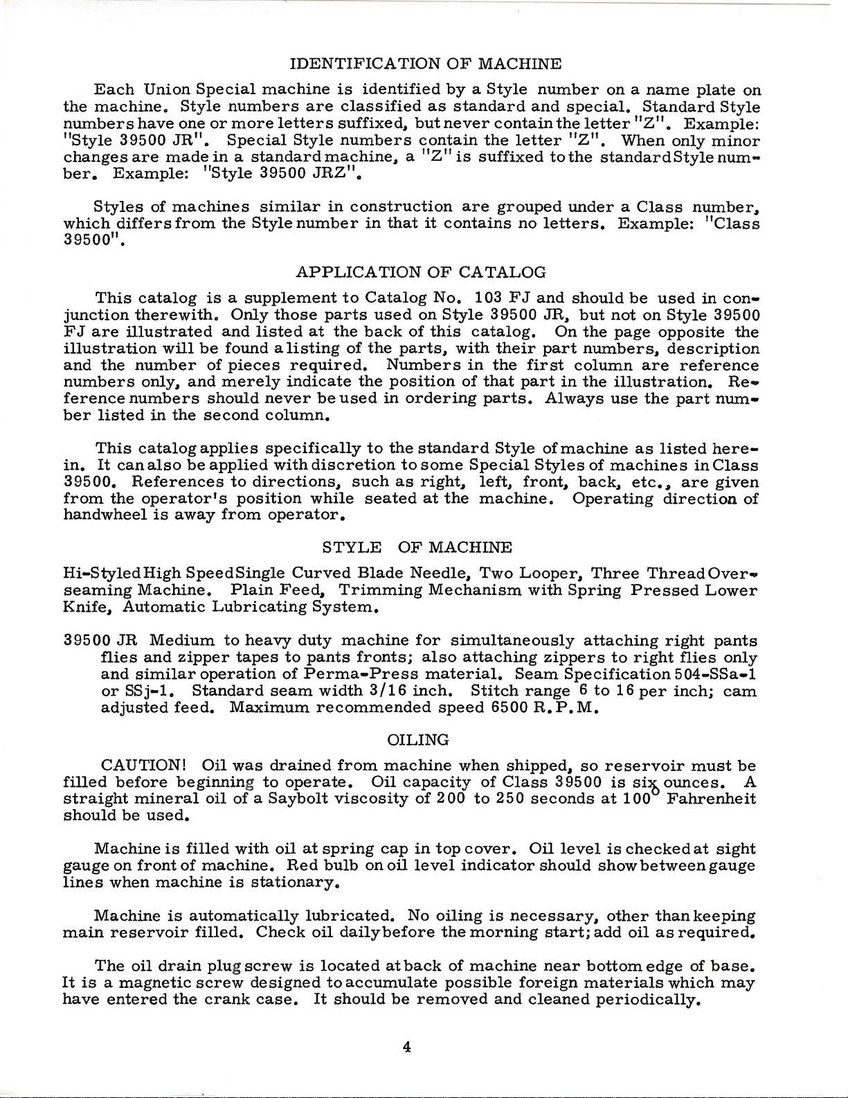
The
Style
parts
39500
illustrated
JR,
but
not
on
the
preceding pa
used
on
Style
ge
39500
and descr
FJ.
ibed
below,
represent
the
parts
that
are used
on
Those
and
39500
Use
Catalog No.
Re
fe r
indicate
Re
f.
o.
1
2
3
4
5
6
7
8
9
10
11
12
13
14
15
16
17
18
19
20
21
22
23
24
25
26
27
28
29
30
31
32
33
34
35
36
37
38
39
40
41
42
43
44
4
46
47
48
49
50
51
52
parts shown
FJ.
ence
numbers
they
are
Part
N
o.
39
592
39592
39592
39592
39 592 AE- 4
39592 AE-8
39592
39
592 AD
39592
39592
8372 A
39592 AH
39578
22569
39563
39551 A
154
39563
87
39508
39549
39550
39570
39525
39578
39580
29477
29477
22596 G
22587 M
39516-62
39516-626
39516-627
30-92 Blk.
C067
40-46
258
39
541 A
5
39
540 B
22528
22 KH
39
505 AM
39
505 AF
39
524 AK
39520
39530
39530
395
30
87 u
28
39
563 H
43139
39
568 L
39
568 B
3
76
39
568 E
in
phantom
103
F J
that
component par
AB
AA
AC
AK
AJ
AF
AL
are insi
s
B
F
GAS
G
u
A
s
TA
A
KE
JN
5
E
1-22
8 Blk.
-7
AJ
v
w
A
A
views
(Style
Upper Looper Tension
Needle
Lower
Tension
Upper and
Needle
Spr
ing
Thread
Tension
Tension
Washer, for
Nut,
Fabric
Screw, for
Top
Needle
Needle
Needle
Screw,
Upper
Lower
Lower
Upper
Needle
Chip Gua
Throat
Crankshaft
eed
F
Screw, for main
Screw, for
Main Feed Dog, marked
Chaining Feed
hroat Plate,
T
Presser Foot,
Needle
Nut,
Upper Looper Thr
Lower Looper Thread Eyelet--------------------------------------Screw,
Auxiliary
and
bearing no
39500
de a bracket
ts
for
Cover
Needle Driving
Needle Bear
Needle Bear
Needle Bear
Wood
Cork
Washer
Nut
F
Vent
Driving Eccentric--------------------------------------------
Presser
E dge
Hinge
Screw, for
Screw,
for
FJ)
for
of a complete
Ten s
ion
Looper
Spr
ing F
Low
Thread
Shield
Tension Disc
Disc Felt----------------------------------Post-----------------------------------------------------
tension post
Guard
top
Needle Thr
Clamp
----------------------------------------------------------
Thread Cam
for
needle
Looper,
Knife-----------------------------------------------------Knife Holder-----------------------------------------------
Knife------------------------------------------------------
Guard,
rd
------------------------------------------------------
Plate
and
Plug--------------------------------------------------
Plug--------------------------------------------------
--------------------------------------------------------
eed
Driving
Plug---------------------------------------------------
cha
Guide, mar
Spring
Thread Eyelet
looper thread
for
looper thread
Looper Thread Eyelet------------------------------------
or
Nut, green
Tension
errule
er
Looper Threa
Tension
----------------------------------------------------
tension
---------------------------------------------------cover
Washer---------------------------------------------
thread
marked "CC"
front-----------------------------------------------
and
Lower
Needle Driving Arm Crank Assem
Screw, for
Screw, for
ing, .
ing, .
ing, . 0627 i
----------------------------------------------------
feed dog------------------------------------------
in ing f
Dog,
m ar
ked "BX"-----------------------
with
Foot Bottom, mark
------------------------------------------------
hinge s
for edge gui
ead Eyelet---------------------------------------
refe
rence num
all
parts
not illustrated
box
on
part
----------------------------------------------
post
---------------------------------------------
needle
ead
Pull-off
Arm
Eccentr
eed dog
mar
bottom
---------------------------------------------
the picture
or
assembly.
Description
Nut,
blue
-----------------------------------
----------------------
Nut,
red------------------------------------
-------------------------------------------
Spr
Kni
needle driving
needle
0625 inch diameter-------------------------0626 inc
"CT",
ked "CJ",
ked
pring----------------------
eyelet
d T ension Spr
ing
-------------------------------------
------------------------------------------
thread
Eyelet
cam
Crank
"H"
de----------------------------------------
eyelet------------------------------------
-----------------------------------
--------------------------------------pull-o
--------------------------------------
fe
Suppo
and
driving arm
h di
nch diam
ic
Key-----------------------------
--------------------------------------teeth
mark
ed
-------------------------------------
screw---------------------------------
ber
s,
are
common
or described
plate
and
hav
ing
--------
eyelet---------------------------
ff
------------------------------
rt Bracket-----------------------
Connecting Ro
arm crank
ameter------------------
eter--------------------------
cut
22
teeth
cut
"AV"
ed
----------------------------
"AV"---------------------------
bly
d A
--------------------
connecting rod
per inch------------------
22
per inch---------------
e i
-
-----------------
----------------ssem
-
----------------
-
to
Styles
in this
ndented descripti
-
------------
-
-------------
bly--------
-----------
---------
-
-------
-
39 5
catalog.
-
----
-----
00
ons,
Amt.
Req.
3
1
2
1
1
1
1
1
1
1
1
1
1
1
1
1
2
28
28
28
1
1
1
1
1
1
1
1
1
1
1
1
1
1
1
1
1
1
1
2
1
1
2
1
JR
1
1
1
3
2
1
3
6
3
3
3
1
1
15
Page 16

,...o
...
...
'
Q
WORLD'S
,..,lf
FINEST
QUALITY
*
,,
•'
INDUSTRIAL
SEWING
MACHINES
UNION
SPECIAL
maintains sales
facilities throughout the world. These offices
aid
you
in
the selection of
equipment for your
Special representatives
tory trained
promptly
tiolJ,
there
and
is
serve you. Check with
ATLANTA,
BOSTON,
CHICAGO,
DALLAS, TEXAS
LOS ANGELES,
NEW
PHILADELPHIA, PA.
MASS.
YORK,
GA.
ILL.
N.
CAL.
Y.
particular operation. Union
and
and
are
able
efficiently. Whatever your loca-
a Union Special Representative
him
the
service men
to
serve your needs
today.
MONTREAL,
BRUSSELS, BELGIUM
LEICESTER,
LONDON,
PARIS, FRANCE
STUTTGART, GERMANY
and
service
will
right sewing
are
fac-
to
QUEBEC
ENGLAND
ENGLAND
400
Representatives
MACHINE
N.
FRANKLIN
industrial
and
cities
distributors
throughout
COMPANY
ST.,
CHICAGO,
in
the
all
Important
world.
ILL.
60610
 Loading...