

Page 1
FEED
ECCENTRICS
(Continued)
The
- 4,
- 26, -
-5,
28, -30, -32
machine.
use
number
sired.
After
t
hrough
threaded
wire
and
(A).
on
through
following
- 6, -
7,
Additional
39540
Example
INSTRU
thread
back
thread
down
Then
stitch
number
- 8, - 9, , -
34
, -
eccentrics
B
with a minor
:
"39540
B-5"
CTIONS
comes
from
eyelet,
through right
thre
thread
ad
continues
guide
feed
10, -11,
36, -40.
may
number
FOR
THREADING
THREAD
cone
then
hand
down
hole
between
(B).
eccentrics
-12,
- 13, -
Only
be
ordered
suffixed
STA
on
thread
through
of
each
14, -15
one
separately
to
STY
ND
stand
front
pair
tension
ar e
available
, -
eccentric
indicate
LES 39500
(R,
thread
of
holes
discs
under
16, -18,
is
supplied
.
To
order
number
J & K
Fig. 1),
eyelet
in
tension
(AD),
through
- 20, -
of
it
is
(S).
No.
39540
22, -24,
with
an
eccentric,
stitches
brought up
Next
thread
slot
guide
(AE)
B:
each
de
-
it
is
,
Only
Parts
It
are
will
threading
Before
ing
by
position
direction
turning
.
Be
tension
discs
Double
(C,
Fig
. 1)
pull-off
looper
lo
oper
right.
thread
(
Rig
parts
placed
lower
sure
(D).
II)
ht
involved
in
their
in
relative
simplify threading
looper
beginni
until
presser
threads
(AD)
ng
and
first
to thread
needl
foot
,
as
in
e (L) is
release
they
diagonal
TO
end
is
of
from
Lead
guide
all
eye
thread
right
to
thread
(F).
the
way
of lower
and
left
behind
Turn
to
looper
threading
positions
th
is
,
needle
,
swing
at high
come
THREAD
lead
.
it
NOTE:
handwheel
the
left;
can
THREADING
are
shown
for cla
machi
second
ne
to
. )
clo
th
plate
position; release
bushing
from
slots
(AE)
(P) and
the
in
LOWER
through
both
Thread
fabric
be
gua
in
then
threa
r d
operating
thread
ded
in
threading
rity
.
follow
open, turn
swing
tension
tension
LOOPER
eyes of
mu
st
pass
(E)
and
direction
through
easily
if
diagram
recommended
handwheel
pressure
presser
thread
posts
lower
in
thr
ough
guide,
(AC). C
looper
front
both
until
both
twee
eyes
zers
on
arm
of
looper
holes
are
(Fig.
sequence
in
ope
presser
(G)
are
between
thread
thre
of
heel
of lower
from
in
left hand.
1).
of
rat-
foot
out of
eyele
t
ad
frame
left
to
~
•
•
"
<
~
•
•
(
~
c
C'
~
•
~
11
~
TO
•
position
eyelet
thread
tension
proper
Turn
.
(N),
pull-off
The
amount
nuts
stitch
handwheel
Insert
under
need
neck
eyelet
of
tension
(A.A, Fig
for
matio
in
operating
le
thread
of
top
(M).
. 1) .
n.
on
THREAD
from
cover
Thread
THREAD
needle
Tension
THE
direction
back
casting
needle
TENSION
and
on
looper
threads
7
unt
to
,
then
from
NEEDLE
il needle
front
, t
right
front
.
threads
shou
(L,
Fig
hrough
to
left
is
regulated
ld
be
. 1)
eye
through
only
enough
is
of
by
at
its
needle
hole
in
two
to
highe
st
thread
needle
knurled
sec
ure
Page 2
Be
sure
machine i s
STARTING
threaded
according
TO
co
OPERA
thre
TE
adi
~LES
ng
diagram (Fig
39500
J & K
. 1, page 8).
front
freely
required
position
•
>-
...
z
0
With thr
to
Operate machine
.
Swing
While sewmg
ead
tensions
back
for
needle thre
location
presse
the
r foot
on
stitch
ligh
t ,
set looper thread
.
slowly, without
mater
ad
eye
into
shou
position;
ial,
let
ld
check
be
(N)
LOWER
presser foot
insert
NE
EDLE
needle thread
drawn
farther
on
needle
to
LOOPER
eyelet
in
place,
materi
THREAD
the rear.
al;
control
downstroke
THREAD CONTROL
(C) about
to
sew
slowly.
CO
NT ROL
as
. To
horiz.ontal
make
follows: About
sure
increase
chain
thread
and m
forms and moves
75%
the
middle
of
needle thread
draMl
on
downstroke,
of its
off
tongu
:.:
o5
..,
enough
<)'
elet
Wi
th
material
so
thread
(C)
should
0 Frame lo
0
of
looper
11'1
(H)
o-
M
11'1
...
...
>-
....
Ill
tl>ese
Before
tensions
•
SKIPP
oper
heel
proce
will
I
1\
G:
under
is
a
be about
tl>read
eyelet
eding,
not markedly
For
presser
little
guide
t>alance
occasional
foo t ,
slack
horizontal.
(f)
at
the
time lower
both
effect
skipping,
set
when
should
spreader reaches
tensions
SPECIA
lower l
be
set
looper
THREAD
to
the purl.
L
check
ooper thread
its
extreme
with
give
its
left
i s at extreme
TENSIONS
a normal app
ADJUSTMENTS
and/
or
adj
ust
eyelet (C, fi
left
hand
left
earing
as
outlined
eyelet
end
stitch
g.
1)
back and do•n
position
approximately
of
its
below:
. Looper
travel.
. Moder
1/8
ate
change 1n
far
thread
inch
right
!.
Recheck lower
2. Recheck
3.
Check
past
Settings
sk
ip
is
definitely
sli¢>t!y one! bringing
change,
C..\l'
left
increase
TION:
position, or
spreader
clearance
needle
1 and 2
not a needle
loope
l.oo
!'er thread
stitch
looper -needle
-
lo~<
er
between
.
should
eyelet
r thread tens
be
ho
nust, as
will
appear
les
setting
loopel' ctossinf_.
needle
made
loop
in
ion
and
quite
skip,
close
as
before
tisht
spreader
carefu
reposition
to
much
, be slightly
on top
.
See
:Oee "Setting tloe
lly.
bend in
as
possible
side
16
"Setting
.
See that
If
it
can be determi ned by appearance t
looper
looper thread
slack as
.
thread
without di
tl>e
Needle",
spreader
eyelet
spreader
page
Spreacet·",
moves
(C) by lowering i t
pull-off
storting
reaches its
11.
page
far
(D).
stitch
12.
enough
After th
.
extreme
left
hat
i s
Page 3
Be
sure
machine
STARTING
is
threaded
TO
OPERATE
according
to
threading
STYLES
diagram
39
500 L & M
(Fig
. lA,
p.
9).
ll~th
and
in
Operate machine
off
the
Sw·ing
llhile
required
To
the
rear.
thread
the
middle
tongue
presser
sewing on
for
incre
the
ase
tensions
of
freely
foot
stitch
thread
light,
their
slowly,
.
material,
front
1nto
should
dr~n
set
upper and low
to
back
without
position,
locations
presser
ins
NEEDLE
check
be
on downstroke,
needle
drawn on
foot
ert
in
materia
THREAD
thread
needle
position
do~nstroke.
er
looper
.
place,
l,
and
CONTROL
control
needle
thread
to
sew
as
follows
thread
make
slowly
eyelets
sure
.
: About
eyelet
(C &
that
chain forms
60?1
(R, Fig.
E)
about
of
lA)
hori
needle
farther
wntal
and
thread
rooves
to
•
>
-
2
c
right
lower
upper
Set
lower
Frame
of
lower
1\lth
looper
looper
loope~
looper
looper
material
thr
ead
reaches
thread
thread
heel
under
eyelet
the
LOWER
eye
let
guide
(G)
eyelet,
should
when
UPPER LOOPER
presser
(E), and back
left
end
foot,
of
LOOPER
(E,
Fig. lA)
be
lower
set
upper
far
its
stroke.
THREAD
about
set
with
looper
is
THRE
looper
enough so upper
CONTROL
horiwntal
its
left
at
the
AD
CO
thread
and
hand
left
eyelet
end
NTROL
eyelet
looper
thread
all
of
(C,
the
way
forward
approximately
its
stroke.
Fig. lA)
is
a
to
little
1/8
rest
slack
in its
inc
on
top
when
slot.
h
of
:E
Oi
-
c
c
"
0
f':
..
"
-
>
...
"
Position
thread
looper thread
tensions
To
reduce mount
of
l
o~~r
.
tension.
looper
of
lower
POSITIONING
thread
looper
at
the
thread
THE
edge
1n
is
the
SQUARE
located
stitch,
17
EDGE
by
balancing
or
close
the
needle
edge
more,
and upper
1ncrease
looper
lower
Page 4
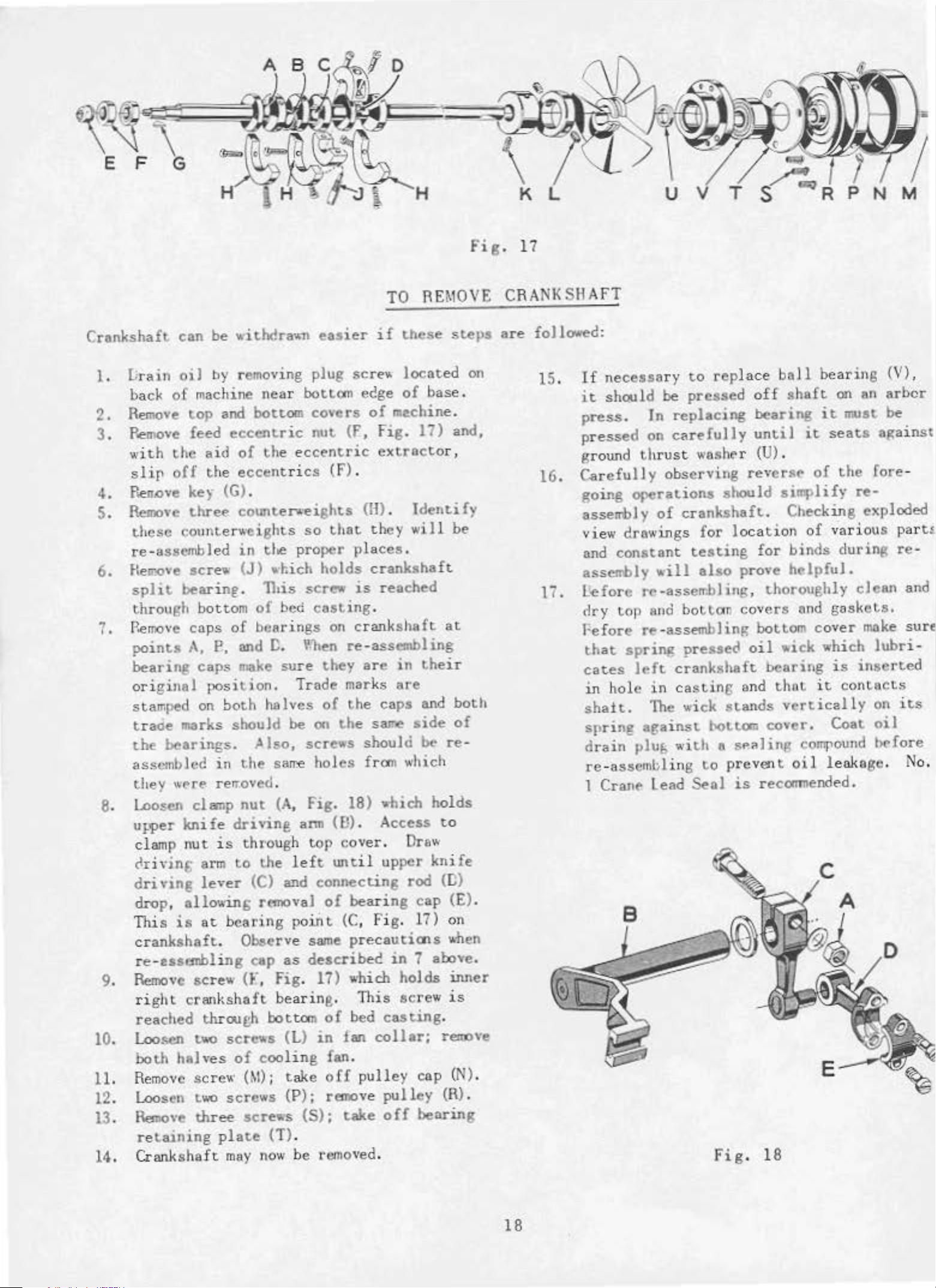
Fig.
17
Crankshaft
1.
~
rain
back
2.
Remove
can
oil
of
machine
top
be
by
and
3. Remove feed
with the aid
slip
4 . Ren.ove ke)· (G) .
5.
Remove
these
re-a
6.
Hell'Ove
split
through
7.
P.emove ca
points
off
the
three
counterweigh
ssembl
ed
sere
..
bearinr
bottom
ps
A,
£?,
bearing caps
ori
gin
al
posil
stamped
trade
the
assembled
they
8. Loosen
uwer
clamp
clri vin& arm
driving
drop,
This
crank
re-usanb
9.
Remove
right
reached
10
.
l...oo
sen
both
1
1.
Remove
12. Loosen two
13
.
Remo•·e
retaining
14
. Crank
on
both
marks
bearings.
in
WP
rf!
rerroved.
clsnp
knife
nut
is
lever
allowing rEmOval
is
at
shaft
. Observe
ling cap
screw
crankshaft
through
two
halv
es
screw
three
plate
sha
ft
with<!ra"n
remov
eccentric
of
eccentrics
coiDite,.,...eights
in
·
(J)
.
of
and!:.
make
should
t.he sarre
nut
drivine
through
to the
bearing
ing
near
bottom
the eccentric
ts
the
..
hich
This
of
bed
bea
rings
sure they are in
..
ioo.
halves
~)so,
(A
(C)
and
eaner
plug
bott<ltn
covers
nut
so
proper
holds
screw
cMting
¥-l•en re-as
Trade
of
be
on
screws
holes
,
Fig
arm
top
left
connecting
of
poii>t (C,
same
as
describe<!
(F,
Fig
.
17)
bearin
bottom
scr.,..s
of
coo
(M);
screws
screws
may
now
(L)
lin
take
(P);
(1')
of
in
g fan.
(S)
.
be
removed.
TO
if
screw
ecge
of
(f,
fig.
extra
(f).
(1-1)
.
that
on
.
(B)
IDitil
g.
off
remove
;
they
places.
crankshaft
is
reached
.
crankshaft
sembling
mar
ks are
the
caps
the
sarre
should be
from which
18)
which
. Ac
cover
. Draw
upper
bearing
Fig.
precauticns
which
This
bed
casting.
fan
collar;
pulley cap
pulley
take
off
REMOVE
these
locat
of
me.chine.
cess
in
holds
screw
ed
base.
11)
cto
r,
Identify
will
at
their
and
side
re·
holds
to
knife
rod
<nl
cap
17)
on
,.h
7 a bove.
is
rem:~ve
(R).
bearing
steps
on
and,
be
both
of
(E)
.
en
inner
(N
).
CRANK
are
foJJ....,d:
15. If
16. Ca
l7
SH
AFT
necessa
it
sh<~ll
press
pressed
ground thrust
going
asserrbl y of
.
refull
r y
to
d
be
pressed
In
replacing
on
car~fu)]y
washer
y
observing
orerations
crankshaft.
replace
revers~
should
view drawings for location
and
assembly
.
L'efore
dry top
Fe
that
cates
in
sha
sprin8
d
rain
re-ass
1
constant
re
ond
fore
re-assembling
spring
]rft
hole
it.
in cas
The wi
against
plu(; witlo a
embli
Cran~
lead
testing
,·ill
-
also
assen.bl
bottor
pressea
crankshaft
tin
ck
~~tom
ng tO
Seol
Fig.
prove
ing, thoroughly
covers
oil
s
And
stands
sP.a!in~
prevent
is
boll
off
bearing
until
(U) .
simplify
for
bottom cover
•ick
bearing
thot
vertically
bearing
shaf
t
on
on
it
must be
it
seats
of
the
re-
Checking
of
binds
h~lpful.
ond
which
it
exploded
various
during
clean
gaskets.
make
is
inserted
contucts
cover. Coat oiJ
compound l>t'fore
oil
leakage
recomnended.
18
(V)
,
arbcr
against
fore
-
pa
r t~
re·
and
sure
lubri
on
-
its
.
No
.
18
Page 5
ILLUSTRATIONS
ORDERING
REPAIR
PARTS
•
This
various
position
the
parts
particular
Numbers
position
ordering
Component
by
indenting
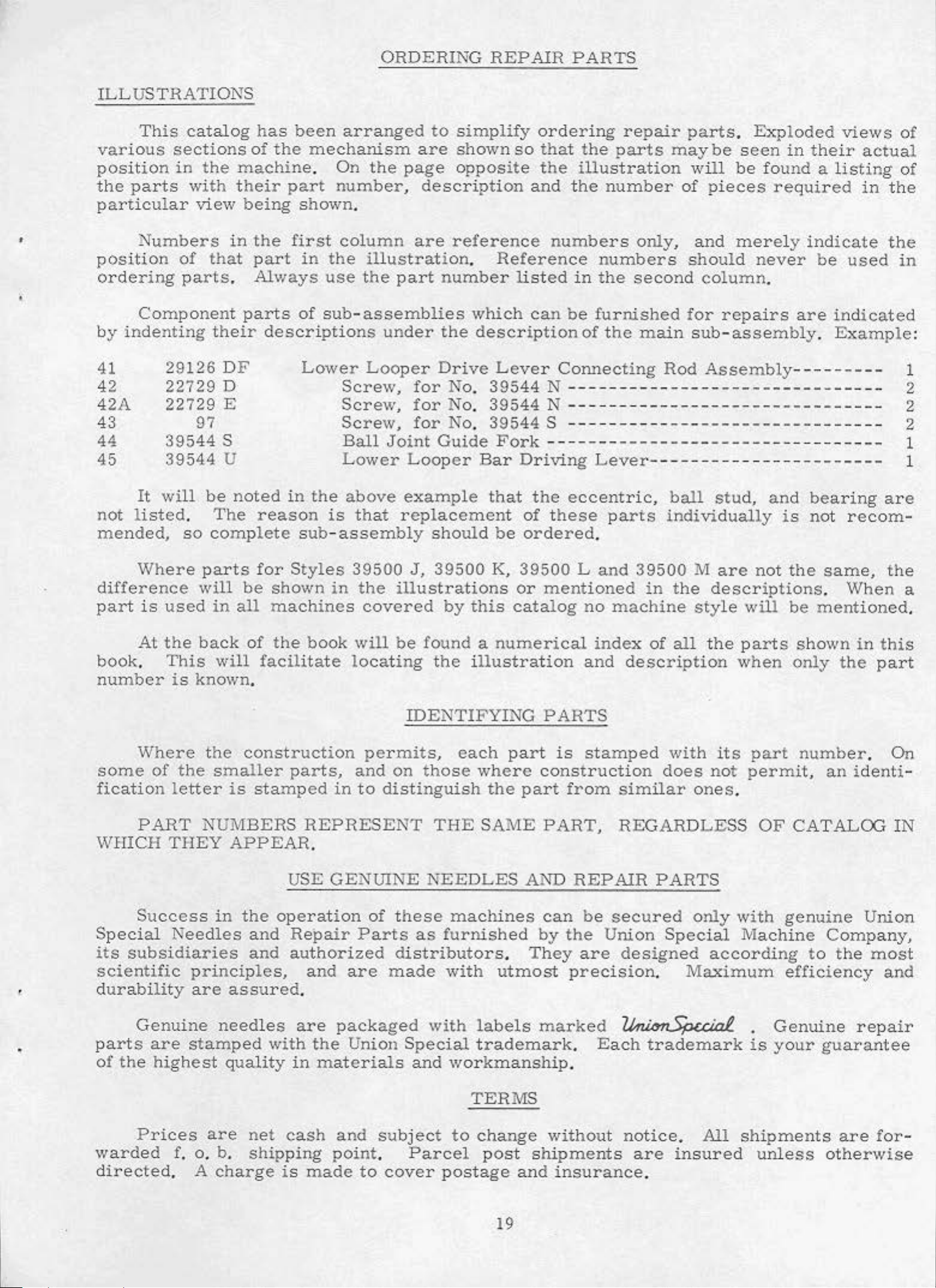
41
42
42A
43
44
45
29126
22729
22729
39544
39544
catalog
sections
in
the
with
view
in
of
that
parts
.
their
DF
D
E
97
s
u
has
of
machine
their
being
the
part
Always
parts
been
the
part
shown.
first
in
of
descriptions
Lower
arranged
mechanism
.
On
the
page
number,
column
the
use
sub-assemblies
illustration.
the
Looper
Screw,
Screw,
Screw,
Ball
Lower
are
part
under
for No.
for
for
Joint
Looper
to
simplify
are
shown
opposite
description
reference
Reference
number
which
the
description
Drive
No. 39544 N ----------
No.
Guide
Lever Connecting
39544 N ---------39544 S ----------
Fork
Bar
ordering
so
that
the
and
numbers
listed
can
---
Dr
iving
be
repair
the
parts
illustration
the
number
numbers
in
the
furnished
of
- ---------------Lever-
second
the
may
only,
main
Rod
-----
--------
-
--
of
--
------
parts
wi
and
should
for
sub-assembly
.
Exploded
be
seen
ll
be
found a
pieces
mere
column.
repairs
Assembly
-----------
------------
required
never
- -
------
- -
-----------
--
------
in
their
ly
indicate
be
are
.
-----
views
actual
listing
in
used
indicated
Example:
----
- -
---
- -
---
-----
- -
- 2
----
of
of
the
the
in
1
2
2
1
1
It
will
not
mended,
difference
part
book
number
some
fication
WHICH
listed.
Where
is
used
At
the
.
This
is
Where
of
letter
PART
THEY
be
noted
The
so complete
parts
will
in
back
will
known.
the
the
smaller
NU
reason
for
be
all
of
facilitate
construction
is
stamped
MBERS
APPEAR
in
the
is
sub-
Styles
shown
machines
the
parts,
assembly
in
book
in
REPRESENT
.
above
that
39500
the
covered
will
locating
permits,
and
to
example
replacement
illustrations
be
on
distinguish
that
of t
should
J,
39500
by
found a
the
IDENTIFYING
each
those
THE
be
ordered
K,
39500 L and
or
this
illustration
catalog
numerical
par t
where
the
part
SAME
the
eccentric,
hese
mentioned
PARTS
is
construction
from
PART,
parts
.
no
machine
index
and
stamped
similar
REGARDLESS
ball
individually
39500
in
of
description
M
the
style
all the
with
does
ones
descriptions
not
stud,
are
will
parts
when
its
permit,
.
and
not
part
OF
bearing
is
not
the
be
shown
only
number
CATALOG
recom-
same,
.
When
mentioned
in
the
an
identi
are
this
part
.
the
a
.
On
-
IN
Success
Special
its
subsidiaries
scientific
durability
Genuine
parts
of
warded
directed
the
Prices
are
highest
in
Needles
principles,
are
stamped
f. o. b.
. A
assured
needles
quality
are
charge
USE
the
operation
and
and
net
shipping
Repair
authorized
.
are
with
in
cash
is
GENUINE
of
Parts
and
the
made
are
packaged
Union
materials
and
point
to
NEEDLES
these
distributors.
made
Special trademark.
and
subject
.
Parcel
cover
machines
as
furnished
with
with
labels
workmanship
TERMS
to
change
post shipments
postage
utmost
19
AND
can
by
They
marked
without
and
REPAIR
be
secured
the
precision
insurance
are
.
Union
designed
~
Each
PARTS
Special
.
Maximum
trademark
notice.
are
insured
.
only
with
Machine
according
is
All
shipments
genuine
efficiency
.
Genuine
your
unless
Union
Company,
to
the
most
repair
guarantee
are
otherwise
and
for-
Page 6
20
Page 7
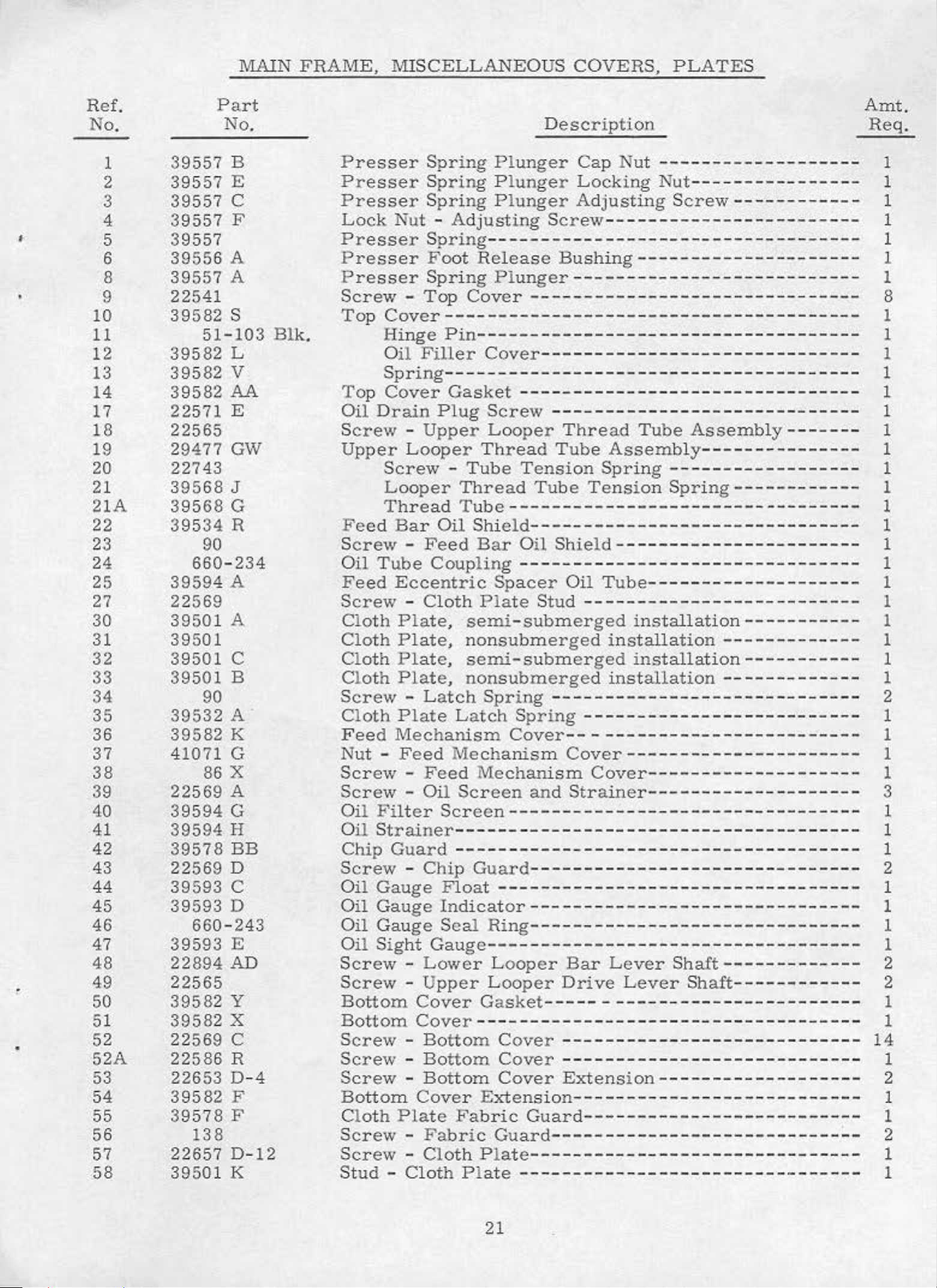
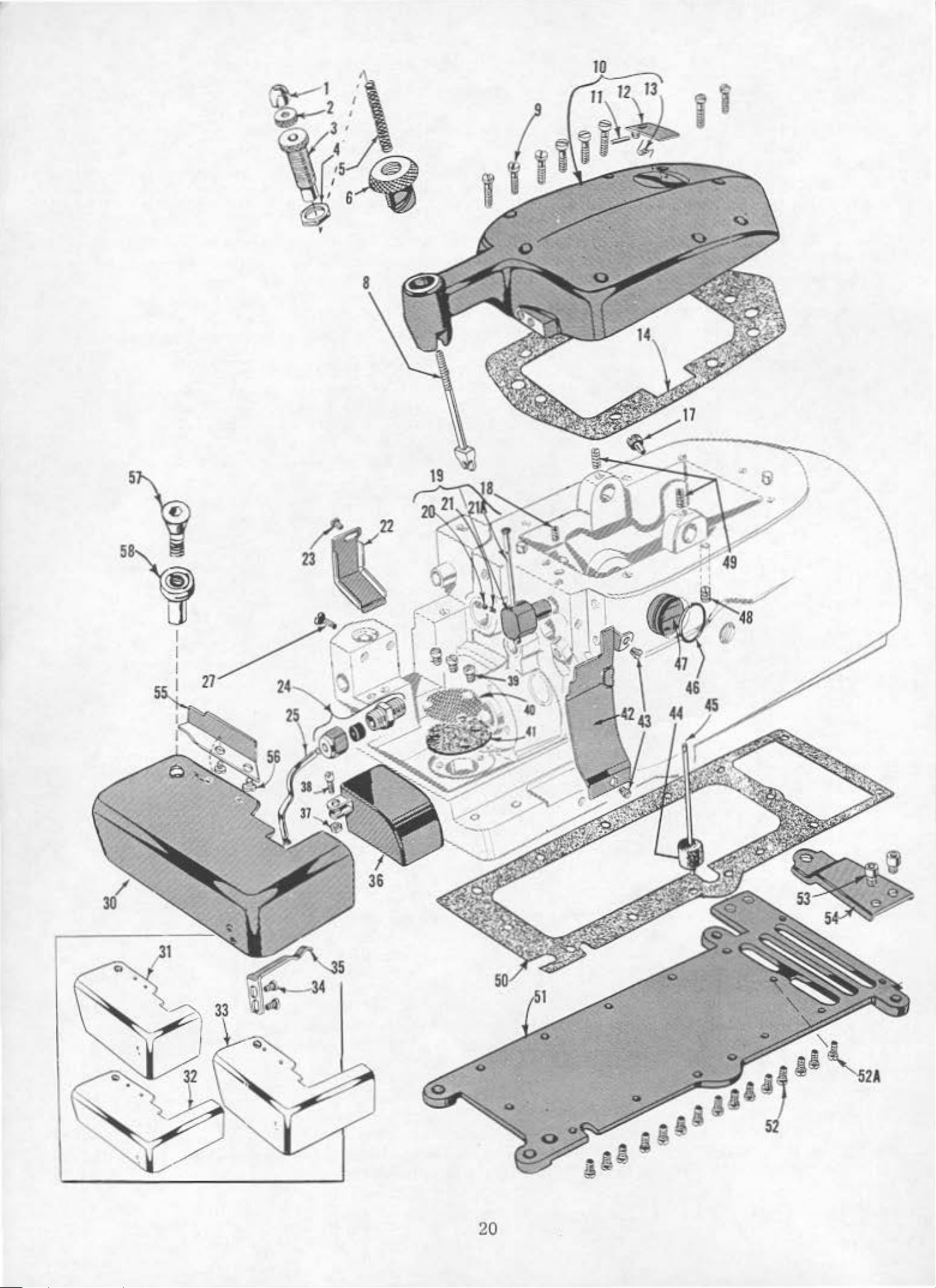
MAIN
FRAME,
MI
SCELLANEOUS
COVERS,
PLATES
•
•
Ref.
No.
1
2
3
4
5
6
8
9
10
11
12
13
14
17
18
19
20
21
21A
22
23
24
25
27
30
31
32
33
34
35
36
37
38
39
40
41
42
43
44
45
46
47
48
49
50
51
52
52A
53
54
55
56
57
58
Part
No.
39557 B
39557 E
39557
c
39557 F
39557
39556
A
39557 A
22541
51
s
- 103
39582
39582 L
39582 v
39582
All
.
22571 E
22565
29477
GW
22743
39568
39568
J
G
39534 R
90
660-234
39594 A
22569
39501 A
39501
39501
c
39501 B
90
39532 A .
39582 K
41071 G
86 X
22569 A
39594 G
39594 H
39578
BB
22569 D
39593
c
39593 D
660- 243
39593 E
22894
AD
22565
39582
y
39582 X
22569 c
22586 R
22653 D- 4
39582
F
39578 F
138
22657 D-
12
39501 K
Blk.
Pre
Presser
Presser
Lock
Presser
Pres
Presse
Screw
Top
sser
Nut
ser
r
-
Cover
H
inge
Oil
Spring
Spring Plunger
Spring
- A
djust
Spring----------------
Fo
ot
Release
Spring
Top
Fill
Cover--
-----
Pin---
er
Cover------------------------------
Spring------
Top Cover
Oil
Drain
Sc
rew
Upper
Feed Bar Oil
Screw
Oil
Fe
ed
Screw-
Cloth
Cloth
Cl
oth
Cl
oth
Screw-
Cloth
Feed Mechanism
NutScrew
Screw
Oil Filter
O
il Strainer
Chip
Screw
Oil
Oil
Oil
Oil
Screw
Screw
Bottom
Bottom
Screw
Screw
Screw-
Bottom
Clo
Screw
Screw
Stud-
Looper
Screw
Looper
Thread Tube
-
Tube
Eccentric
Plate
Plate,
Plate,
Plate,
Plate
Feed
-
-
Guard-----
-
Gauge
Gauge
Gauge
Sight
-
-
-
-
th
Plate
- F
-
Cloth
Gasket
Plug
Upper
Thread
-
Tube
Thread
Shield
Feed
Coupling--------------------------------
Cloth
Latch
Feed
Oil
Bar
Plate
,
semi-submerged
nonsubmerged
semi-submerged
nonsubmerged
Spring
Latch
Mechanis
Mechan
Screen
Screen
-----
Chip
Gauge--Lowe
Upper
Cover
Cover---
Bottom Cover
Bottom
Bottom
Cover Extension--
Cloth
Guard-------------------------------
Float ----
Indicator
Seal
r L
Gasket------
Fa
bric
abric
P l
P l
ate--
Description
Plunger
Plunger
ing
Plunger
--
- -
---
Cap
Locking
Adjusting
Screw------------
Bushing
----
-----------------------
----------
-----
Nut -------------------
Nut
----
Screw--
--
--
--
----------
--
----
- - - -
-
-----------
- -
---------------
-------------------
----------------------------
-------------
Screw
Looper
- -
Spacer
Sp
Cover--
---------------
----------------------------Thread
Tube
Tension
Tube
----------
------
Oil
Sh
Oil
Stud---
-- -
ring
m
Cover-
ism
and
Str a
Assembly------
Spring-
Tension
- - -
ield
-----------------------
Tube-------
-
installation---
installation-
--
-----
--------------------------
-
--------
Cover----
iner-
-------------
-
-----
---------
Ring
Loop
Guard-------
-----
-------
ooper
er
-
--------
Cover--------------------------Cover
Guard---
ate-
-
----------
-
-------------------------
-
----
-
--
Bar
Drive
---------------------------Extension----------------
--
--
-- -
---
----
Lever
Lever
-
-
--------
- - - -
------
--
--
-
------------------
Tube
- - -
--
------
------installation
installation
- -
-
- - - -
- - -
- -
--
--
- - -
--- ---
- - -
- -
---------------------
Assembly-------
-
-----
Spring-
----
- -
----
--
--
- -
--
- -
----------
-
-------
-
-------------
----------------
- - -
------
--
- - - -
-------------------
-
--
--
------
-----------
-----Shaft----
Shaft
------
-
---------
--
-
----
------------
-------------
-----
- - - - -
--------
--
-
------
--
--
-----
-------
-
--------
-
------
-
-- --
-
--
-------
-
----------
-------
--
---
-------
---------
-
------------
------------
-----------
------
--------
-
--
- - -
------
- - -
-
-----
--
----
--------
--
-----------
-
-------
-
-----
- - -
---
- - - - - - 1
- -
-------
------------
--
- -
-------
---
--
--------
----
- -
- - -
--
-----
----
----
- - - -
---
----
-
-
----
--
----
Amt
-
-
-
---
-
--
-
-
-
--
- -
-
- -
--
---
--
- 1
- 1
-
--
- - 1
- 1
.
Req.
1
1
1
1
1
1
1
8
1
1
1
1
1
1
1
1
1
1
1
1
1
1
1
1
1
1
1
1
2
1
1
1
1
3
1
1
1
2
1
1
2
2
1
1
14
2
1
2
1
21
Page 8
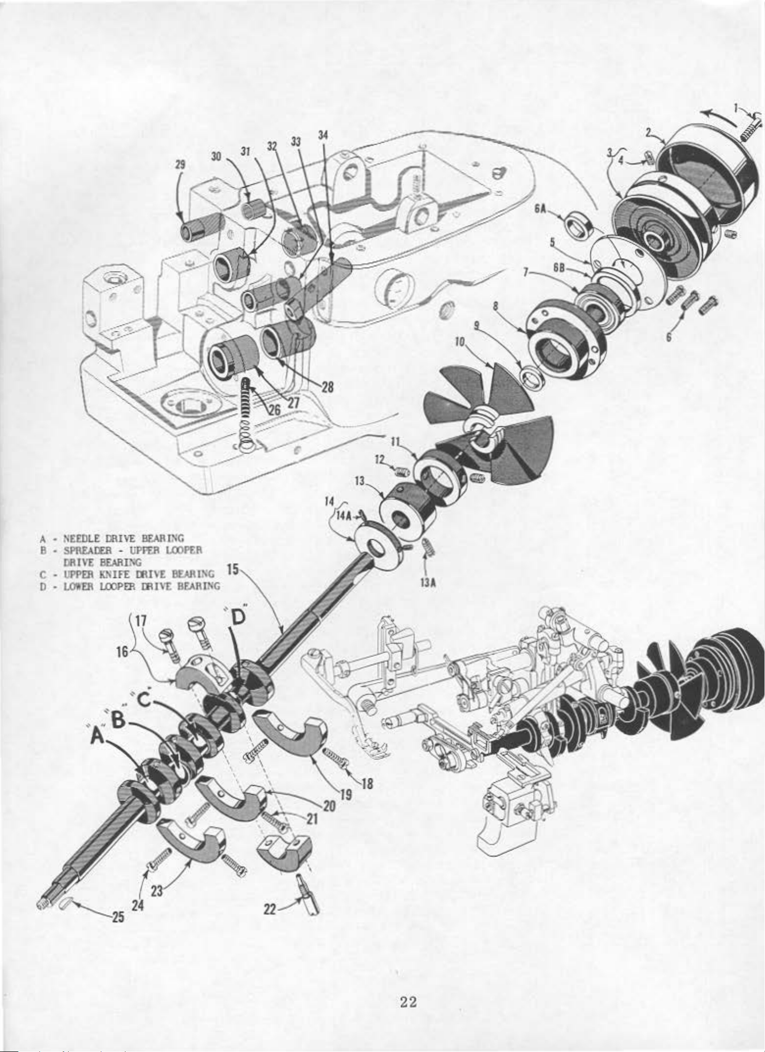
A -
~EED L£
8 -
SPRfADER -UPFER
DR
C -
lJPPEil
D -
LO'!Eil
DfU
IV£
llEARII'G
KNIFE
J.OOI'!ll D\JV[
\'1:
BEAR lNC
D\l'E
LOOPER
llEARJNG
BEARING
22
Page 9
CR.J\.NKSH.J\.FT
MECHANISM
AND
BUSHINGS
'
Ref.
No.
1
2
3
4
5
6
6A
6B
7
8
9
10
11
12
P3
13A
14
14A
*15
16
17
18
19
20
21
22
23
24
25
26
27
28
29
30
31
32
33
34
Part
No.
22769
39521
39521
95
39590
22569
39590
39590
660-268
39590
39590
39591
39591
22894
22565
39590
77
39590
97
22747
39591
39591
22747
39590
39691
22747
3
9541
666-94
39590
39590
39555
39142
39573
39573
39552
39544
A
A
H
s
R
G
J
L
H
D
F
p
Q
D
A
B
B
A
B
N
B
c
E
G
K
AA
B
L
Screw
Pulley
Pulley
Cr
Screw ---
Spacer
Ball
Crankshaft
Crankshaft
Thrust
Cr
Crank
Screw-----
Crankshaft
Screw
Oil
Crankshaft
Cr
Screw
Cra
Crankshaft
Screw
Stud,
Crankshaft
Screw
Feed
Oil
C
ra
Crankshaft
Foot
Foot
Upper
Upper
Needle
Lower
,
for
Cap-----
--------------
Screw
ank
shaft
Collar-
Bearing
Washer
ank
ankshaft Spl
Ch
Chamber
--------------------------------------------
Slinger
Screw
Screw,
,
for cranks
nkshaft
,
for
for crankshaft
,
for
Driving
Wick
nks
haft
Lifter
Li
fter
Knife
Knife
Drivi
Looper
Descr
pulley
-----------------------------------
-----------------------
Ball
- -
-----------------------
Ba
Ball Bear
amber
-----------------------
Bearing,
Collar
----------------------------------------
---------------------------------------for
Counterweight,
Counterweight,
cra
Counterweight, left---------cranks
and
Bushing, left--------Bus
Shaft
Shaft
Driving
Driving
ng
Bearing
-----------------------
Stop
ll
Bearing
-
-------------
Cooling
Cooling
it
Bearing
split
nks
Eccentric
Spring
hin
Ar
Bar
ipt
ion
cap
Collar----
----------------------------------
haft
haft
haft
g,
Bus
Bushing,
m
------
----------------------------Retaining
-
ing
inner
bearing---
split
--------------inner left
hing, left--------------
Ar
Arm
Crank
Bushing
Housing
Fan
Fan Collar------------------
-----------------------
counterweight
counterw
co
unterwei
Key-----------------
m
-
---
-------- ---
Plate
- -
-------
--------------------------
--------------------
--------------------
------------------------
right
right----------middle---------
bearing
right
Bus
Bushing
Bushing---
----------------------
---
------
eight
-------
ght--------------
-------------------
----
----------------
hin
g, left----
,
- -
----
------------------
-----
--------------
-----------------
------------------
rig
- -
-----
--------------
-
--
----------
----------
-
--------------
--
--------------
-
---
---
-----
-
-----------
----------
-
---------
--
- -
--
- -
----------
- -
---
---------
ht -
---
---------
---------------
-------
--
----
-----
-------
------
- -
-
---
Amt.
- 1
---
---
- 1
- - 1
---
-
--
---
--
- 1
- 1
--
--
- 1
Req
1
1
2
1
3
1
1
1
1
1
2
1
1
1
2
1
1
2
2
1
1
2
1
1
2
l
1
1
1
1
1
1
.
:t
Discontinued
*
Discontinued
-
For customer
-
For
Sub-Assembly
customer
repair,
repair,
N
o.
29477
order
order
23
Kit
Crankshaft
JA.
of
Parts
No. 29
and
480
Needle
LB
.
Driving
Crank
Page 10

26A
17
16 15
24
Page 11

Ref.
No.
Par
No
NEEDLE
t
.
DRIV
E Al'ID
FEED
MECHANISM
Description
Am
He
t.
q.
'
1
2
3
4
5
6
7
8
9
10
11
12
13
14
15
16
17
18
19
20
21
22
23
24
25
26
26A
27
28
29
30
34
35
36
37
38
39
40
43
44
45
46
47
48
49
50
51
52
53
55
56
57
58
59
60
61
62
63
87
39578
39578
M
R
22569 B
8372 A
39578
p
22565 F
39
535 c
39
535 F
53634
c
22569
39535
39535
53634
J
D
c
22569 8
22569 G
39534 H
39538
39534
G
39505 J
22528
39505 K
22768
39536
B
A
39540 B- 5
39540 J
18
20
39
536 E
39
536 c
39536 D
39536 B
14077
39563 z
39552
22596 E
50- 774
39551 F
22564
39
568 A
395
68 y
88
B
3955 2
39552
c
A
39552 E
22587
J
39594 N
77
660 - 207
22569 c
39503 c
22758
E
12957 E
39503 D
604
39503
A
22570
39503
Blk
Screw -Fabric
Fabric Guard
Fabric
Screw-
M
ounting
Fabric
Screw-
Feed
Main
Feed
Screw
Fe
ed
Feed
Feed
Screw
Screw
Gaurd, for
M
ounting
Bracket
Guard
Adjusting Pin---
Tilti
Feed
ng
Bar
Bar Guide
-
Feed
Ba
r G
uide
Bar
Bar
Guide, right---------Guide
-
Feed
-
Thrust
Feed Bar Thru
Feed Lift
Main
Main
Feed
Feed
Screw
Chaining
Screw
Main
M
Fe
Feed
ain
Feed Dr
ed
Eccentric
Bloc
Bar---Dog ----
-
Main
F'ee
-
Chaining
Bar
Nut-Crankshaft-----W
ashe
r - - -
---
Nut-Feed Bar Driving
Feed
Fe
Feed
ed
Bar
Bar
Bar
Driving
Spacer
Driving Stud
Nut-Needle
Needle
Thread
Needle--------
Needle
Drivin
Screw -Needle
.
Stop
Needle
Screw
Looper
Looper
Screw
Pin
Clamp Stud-----
-
Looper
Thread
Thread ?ull-off
- Looper
Needle Driving
Needle Drivi
Nee
dle
Driving
Screw
Oil Spla
Screw
-
Oil Seal
Scr
ew
-
Edge
Scre
Swing
Edge
Guide
w -
ing
Guide
Screw -Ad
Edge
Scre
Guide, adjustable, for Style
w - S
-
sher-
Oil
Ring------------
Mounting
Swinging
Arm
justable
tationary
Edge Guide, stationary
, f
Guard
or
-------Style
Styles
Bracket-Washer
Mo
unting
Adjusting
Bracket
Pin-
Guide, left
Washer
Bar
Guide,
Block
----------
Washer
Bar
Gu
Washer
st
Washer-
k--
- - --
ide,
- - - -------
------------
- -
--------------
------
Feed
d Dog - -- -
Dog--
Feed
---------Dog----
Driving
iving
Eccentric
Sp
acer
and Oil
---------------
--
---
- - -
-----
Connection
--------
- -
Clamp
Stud---
Pull-off
-
----
g A
- -
rm-----
----
Driving
-
Needle
Th
Pull-off
Driving Arm-------
read
----
Thread
ng
Arm
Arm
Arm
Crank
Crank
Crank
Connecting
- - -
-----
---
Splasher-------
Bracket------
Mounting
Bracket
Arm, for
Spring
Swinging
Washe
Arm
Edge
Edge
,
-
-----------
39500 J
39500
----
K,
--
- - - -- -
--
-------
L,
- - -
-
------
-----------
--
- - -
-------
-- --
--------left---
- -
--
-
-----
- ----------------------
- -
- -
------
---- - - - -
right-------
- - -
------------
---
-------------
-----
- -
-----------
--
-
--------------------
Connect
ion------
, . 124 i
Slinger-
Stud
-----
--Bus
- - -
---hing-----------------
---------------
------------
- - - -
Eyelet
----
----
---------
------
- -------Arm
----
--
---
- - -
----
Pull-off--- - -
--
Leve
----
r---
--------
- - - - - - - - -
Pull-off Lever-
Thrust
- - - - - Connec
Rod
- -
- - -
--------
W
---tin
----
------
- -
--
- - -
-----------
-----
---
- ---- -
Styles
r,
, f
or
Guide
395
for
Styles
Styles
, f
or
s 39500 J & L --
Guide, for
for Styles
39500 K & M - -
-
-
-------
M - ----
------------
----
- -
--------
----
----
--
- - - - - -
- - -
-
-
----
------
- ------------
-
- -
-- --
------
--
- - - --
-----
-----
-
----
-------
--
---------------------
- - - ---- - -
--
--
- - ----
------
-- - - - ----
--
-----
-
----------
- - -
---
- - -
-
-- --
- -
--
nch
- -
- ---- -
--
--
throw-----
- - - - - - - - -
-------
---
----------------
--
---
--
- -
---.
---
-----------
- - - -
- ---- - -
- - -
---
--
--
---
------------
--
- -
--------
--
-------------
------
- -
-------- -----
-----
----
--
- ----
---
--
-----
------
---- -
------
- ---- - -
- - - - - - 1
-----
------
- - - - - - - 1
--
--------
- - -
--
---
--
--------
- ---- - - - - -
--
--------
---
-----
-
-------
--
- -
-
--------
-----------
---
-----
--------
- - - ----
----- -
---
------------
- -
------
asher--
- -
----
g Hod
-----
------ --
-
-------
---- - -
--
--
-------
-
---
- ---- -
------------
---
- - -
---
--
---
- -
-------
-- - - - - -
----
--- ---
-----
- ~
--------
00 J & L -- - - -
39500 J & L
39500 J & L --------
Styles
35900 J & L
--------
Styles 39500
K & M - -
----
---
--
-
----
--
--
-- --
-
---
- -
--
----
- - - - 2
----
---
-----
----
---
- - - - 1
---
--
----
--
--
-----
- - - 1
---
-----
--
---- 1
--
---
- - 1
---
- - 2
--
--
--
--
----
--
---
--
- - 1
----
---
- -
--
- - l
- - - 1
-- --
---
--
- - - - l
2
1
- 1
2
2
1
1
1
1
2
1
1
2
2
3
1
1
1
1
1
1
1
1
1
1
1
1
1
1
1
l
l
1
1
1
2
1
- 1
2
1
1
2
- 1
1
2
l
2
25
Page 12

m
Tenaion
Nut
~
•
>-
...
z
0
~
oil
...
0
0
11'1
().
I")
Ill
...
...
>-
._
Ill
Tenston
Slot
Tcn~Jion
D
lbrud
Post
Thread
Guld•·-----
--
'
•
-
-
--
~--
Presser
--
.~·
.....
' .
..
'•.
-
'
--
'
Cone
Foot
--
---
---
'
'
..
...
3vpport.
Hcl
cue
---
_
.........
(.:~
.
..
.,.
-
___
Bubia
-------
___
-
____
......
...
-
1
,
•
B Lower
m
Looper
0
fabn.e
IJ
fre.ae
~~
Presser
Looper
Thrud
Looper
Ar•
Thread
Pull-of!
Thrud
Eyelet
Gaide
____
._ ~
"
"'•
Needle
PuJl
Needle
.. o
Tbrud
ff
£yC!Ile t.
Fis.
1
8
Page 13

~\
9
29/
~
28
26
Page 14

Ref
No .
SPREADER
.
Part
No .
/U
PPER
LOOPER
AND
LOWER
Description
LOOPER
DRIVING
PARTS
Am
Req
t.
.
)
•
1
2
3
4
5
6
7
8
9
10
11
12
13
14
15
16
17
18
19
20
21
22
23
24
25
26
27
28
29
30
31
32
33
34
35
36
37
38
39
40
41
42
42A
43
44
45
46
47
48
49
482 c
22894 c
22565
7446 A
1280
39543 R
43143 N
39543 H
29126
CG
22559 A
77
39594
N
22747
41255
B
39543 M
22562 A
39543 p
39543 K
39543 s
22565 H
39543 T
39543 E
22503 F
22
KH
39543 A
39543
22564
G
39560 A
39508 A
22539 K
482 c
22894 c
22894 AD
51235 B
39508 B
39151
39544
77
39544 D
39544 B
29126
DF
22729 D
22729 E
97
39544
s
39544 u
39594 N
77
22539
K
666-255
39594 p
Spreade
Sc
rew -Spreader/Upper
Spreader/Upper
Nut Locking
Locking Stud
Spreader/Upper
Spreader/Upper
Rod
r/Upper
Screw-
Locki
Stud
Assembly
Looper
Collar---------------------------
Lo
oper
ng
Stud-
---------------------
Washer---
-
Spreader/Upper
Looper
L
ooper
-----------
Screw -Connecting
Screw -Oil
Oil Splash
Screw -Guide
Ball
Collar
D
rive
Joint
Assembly------------
Clamp-----
Screw -Collar
Spreader
Spreader/Upper
Bushing
Screw-
Cam
Cam
Follower
Follower
Screw -Locking
Splasher----------
er
--------------------Fork
Guide
/Upp
Fork
er
Looper
Looper
and
Cam
Cam
Guide--
Guide----------------
-----------------------Lo
cking
Clamp
-----------
--
----
Clamp-
Screw -Spreader/Upper
Spreader/
Spreader/Upper
U
pper
Looper
Looper
Screw -Spreader/Upper
Spreader-
Upper
Plug
ower
L
Looper-
Screw-
Looper
Screw
Screw-
Lower
Looper
Lower LooperNut
Lower
-
Lower
Looper
Screw -Connect
L
ower Looper
Lower Looper
Lower
Rod
Looper
Assembly---------
Screw,
Screw,
Screw,
Ball
Lower
Oil
Splasher
Screw,
Plug
Felt,
Oil
Screw
for
Collector
Styles
Styles
Lower
Shaft
-
Collar-
Lower
Looper
Bar
------------------------------
Looper
Bar--
ion Link Pin
Bar
Bar
Bar
upper
lower
for
No
Joint
Gui
Looper
------
for
No.
-
39594 N
Lower Looper
No. 39544 N-
Pla
te
39500 J & K
Looper
Collar-
---------------
Driving
Bar
-- --
Connection
Connection
Dri
--------------------------
-------. 39544 S
de
Fork-----
Ball
--
---
(Not
Shaft
Looper
Drive
-----------
Collar
Drive
Lever
-----------
Shaft
-
---------
Looper
Drive
Drive
Rod Ass
Lever--------------Lever
-
---------
----
embly
Connecting
----
------------------
-------
--------------------
- Spreader
-----/Upper
--
-------------
--
--
--
--
-------
----------------------------
Shaft Thrust Washer
Shaft-
-
Clamp-
-- -------------------
--
- -
-----------------
-
-------------
- - -
---------
----------------Looper Holder
Hol
der
Holder
Looper
39500 L & M
Co
--------Holder
------
Shaft-
--
--
lla
------
---------
---
-------
r---
-
-----
-----
Bar
Driving
Le
-----
--
--------
ver
-
--
Lever Shaft-
Shaft
--------------------
- -
--------------------Link
Pin---
Linl<---------------------
ving
Lever
----------
-
--
- -
and
Connecting
--------------------
---
--
---------------------------
----
Driving
- -
----------------------------
Lever
--
-------------------Shaft-
-------Illustrated)
-----
--
- - -
- -
--------------------
-
Lever
Shaft---
--------------
- -
---
--
-
------
Dr
ive
Lever
-----------
-
----
---------Looper
--
----------
- -
--
- -
------------
- -
---
-----------
-
--
---
-
----
------
Collar--
---
-----
.
-----------
----------------
--
-----------
-------
- -
-----
- -
-----------
--------------
---------
-------
----- -----
--
-----
--
-----
--
------------
-
--
--------------
-----------
-----
-- -----------
-
---
------------
-----------------
--
----
--
----
----
-------
----
----
--
------
---
----
----
----
-
--
- -
--
-------
------
-
------
- -
---
-- --
----
------
--
----
------
-------
-
-
--
----
-------
----
--
--
- - -
--
---
---
--
---
---
--
--
--
---
1
2
2
1
1
1
1
1
1
4
1
1
1
1
1
1
2
1
1
1
1
1
1
1
1
1
-
1
1
1
1
-
1
2
2
1
-
1
1
1
2
2
1
1
2
2
2
1
1
1
l
l
1
1
27
Page 15

12
14
1
28
Page 16

UPPER
AND
LOWER
KNIFE
ME
CHANI
SM
•
Ref.
No.
1
2
3
4
5
6
7
8
9
10
11
12
13
14
15
16
17
18
19
20
21
Part
No.
39573
22587
39573
55235
6042
55235
39573
39573 H
39571
39572
22738
39570
39571 F
39571
14077
22585
39525
22585
39525
22524
39524
J
J
E
D
A
E
A
c
A
J
B
A
A
A
J
Upp
Upper
Upper
Upper
Upper
Upper
ScrewUpper
Upper
Upper
Nut
Screw-
Needle
Screw-
Ne
Screw
Throat
er
Screw
Locking
WasherNut-
-
edle
Knife
Knife
Knife Driving
Knife
Knife
Knife
Holder
Knife,
Knife
Knife
Upper
Needle
Guard,
Needle
Guard,
-
Throat
Plate,
Driving
-
Connecting
Driving
Stud-
Driving
Driving
Driving
Clamp
Holder
Block
for
Styles
Clamp
Chain
Knife
Guard,
front
Guard,
rear-
Plate
3
/16 inch
Description
Connecting
Rod
Lever
Driving
Lever
Leve
r----------------
Arm
------------
Washer
Arm--
Stud
Block
-------
Guard
Assembly
------
-------------------
----
-
Clamp
39500
------
-------------
front
----------
rear------------------------
- -
----
-----wide
Rod
---------
Le
ver--------
----
--
--------------
-----Nut
J & L
--
-----
--------
--------
----
-----
seam,
---
------------
- -
----
-----------------
----only
-------
------
-----------------
for
------------
------
-
--
------
-
--------
---------
---------
--------
--------
-------
------
-----
---------
-----
------------
----------
----------------
----------------
-
-----Styl
-
------
-------
es
-------
---
---
---
----
-----
----
-----
--
--
- 1
- 1
- 1
--
Arnt.
Req
.
1
2
1
1
1
1
1
1
1
1
1
1
1
1
1
1
1
21A
22
23
24
25
26
27
28
29
30
31
32
33
39524
39550
39550
39549
39550
39550
22588
22729
39550
14077
22892
39580
22653
K
E
B
J
M
L
A
B
c
B
A
B-12
39500J
Throat
39500
Lower
Lower
Lo\ver
Knife
Lower
Screw
Screw-
Lower
Nut -Locking
ocking
L
hroat
T
Screw
& L
P
lat
K & M
Knife
Knife
Knife
Clamp
Knife
-
Lower
Lower
Knife
Screw
Plate
-
Support
e,
----------3/16
inch
--------
Spring
Holder
------------
Spring
Clamp
Knife
Knife
Holder
Screw-
-
Lower
and
Lower Kni
Brac
------
wide
-
--
---------------
----------
---
seam,
--------
-----
-----------
--
----------
Holde
Holder
Locating
Lower
ket
r
-----
Locking
Stud
Knife
Knife
-----------
Holder--------------
fe
Support
----------for
-
-
-----------
Styles
--
----
---------
-----
----------
-----
---------------------
---
--
---
-------------
--------------------
-----------------Stud
---Holde
Bracket
-----------------
----
------------r
-----------
--
------
-----
--
-----
--------
--
--
--
- 1
1
1
1
1
1
1
- 1
- 1
1
1
- 1
1
2
•
29
Page 17

..
14--Ql
'
30
Page 18

FOOT
LIFTER
,
THREAD
TENSIONS
AND
MISCE
LL
ANEOUS
EYELETS
'
Ref
No
1
2
3
4
5
6
7
8
9
10
11
12
13
14
15
16
19
20
24
28
29
36
37
.
.
Part
No.
39555
39555
39555
660
:39555
B
D
-1
I~
42
22566 B
39555
c
627
22597
E
12538
12865
88
39555
22791
258
39556
39520
39597
A
H
A
D
L
L
22819
39530
22768
B
108
108
512
92 F-2
51292 F- 2
51292 F- 4
51292 F
51292
-4
F- 8
Foot
Foot
Foot
Cotter Pin
Foot
Lifter
Lifter
Lifter
Lifter
Lever
Lever
Intermediate
Lever
Screw -Foot
Foot
Lif
ter
Lever
Screw-
Foot
Screw
Lock
Lifter
- Lev
Nut
Lever
Scre\v -
Foot
Screw
Nut
Presser
P
Ten
Tens
Low
39500
L
Looper
Need
for
Lower
Lifter
-
-
Presser
Lever
Presser
Arm
resser
Foot
Presser
Screw -
Presser
Screw-
sion
er
ion
Need
Pos
Post
le
J & K
ower Looper
Thread
le
and
Styles
Upper
39500
Looper
Description
----------
Spring
Connecting
Connecting
Lifter
Lever
Arm
Lever
-
Arm
er
Arm
Lever
Shaft
Collar------
Shaft
Arm
Arm
----------------
----------
Foot
Stitch
Foot
Hinge
t Nut,
Nut,
Thread
--------------
Thread
Tension
Thread
----
Stitch
Tongue
Hinge
Spring
for
for
Looper
L &
---------------
--------
Lever
Link
--------
------------------
Li
nk
--------
-------
------------
---------------
-------
Arm
-----------------------
Collar
------
----------
--------
--------
-------------
-------------------
Tongue
------
Spring
--
Styles
Sty
les
Tension Spr
Tensi
Sp
on
ring,
Thread
l\'1
--------
Tension
----------
----------
----
------39500
39500
----------
Spring,
for Sty
Spring,
--
----------
--
------
----------------
---------------
---------
----
-------------------
--
---------
----------
--------------
----------
-
----------
-
----------
---- ----
-----
---------
-
---
--------
--------
-----
----------------
-----------------
------
---------
-
------------
--------------------
--
-----
----
-
--
J & K
L & M
ing, for
Tension
---
---------
------------
--------
----------------
---
--------------
----------------
Styles
------------------
for
le
Style
39500
39500
J
Spring,
------------
for
Styles
--------
----------
-------
-----
-----
-----
-
--
-----
-
-----
I<
----
----
---
--
--
--
---
--
---
Amt
Req
- 1
1
1
- 2
1
- 1
1
- 1
2
2
1
2
1
1
1
- 1
1
1
1
1
1
2
3
1
1
1
2
.
.
,
38
39
40
41
42
43
44
45
46
47
48
49
50
51
52
53
54
56
107
107
109
109
35792
35792
39592
H
H
F
22891
22565
22565
c
c
90
39563 s
22569
39568
39568
39568
39568
376
376
43139
43139
39568
73
B
D
L
B
E
A
A
A
A
X
w
22569 D
39563
D
39500
Tension
Tension
Tension
Tension
Ten
Ten
Tension
Screw
Screw -Ten
Screw Screw -
ThreadGu
sion
sion
-
L &
:i\1
Post
Post
Disc,
Disc,
Post,
Post,
Post
Tension
sion
Tension
Thread
ide
Ferrule,
Ferrule,
i\1ounting
Screw -Eyelet
Looper Thread
ooper
L
Looper
Auxiliary
Th
read
Thread
Looper
Screw -Looper
Screw
Nut -Looper
::>iut-Looper
Screw
Frame
Screw
Needle
-
Looper
-
Frame
Thread
-
Needle
Thread
Thread
Thread
--------
for
Styles
for
Styles
for
Styles
for
Styles
Post
Post
, fo r
Post,
Guide
----
---
Mounting
Eyelet
Eyelet
Eyelet,
Thread
Thread
Thread
Eyelet,
Thread
Guide-
Thread
Eyelet
----------
for
Styles
for
Styles
39500
39500
39500
39500
Bracket
Mounti
ng
Styles
for
Styles
----------
-------Bracket
Mounting
-----for
----------------
Styles
Eyelet,
Eyelet,
Eyelet,
Eyelet,
for
for
Guide
--
Lower Loop
Eyelet
--------
----
39500
39500
J &
I<
--------
L & i\1
J &
L &
-----
I<
----------
i\1
- -
Bracket
39500
39500
-
------
------
---------
-----------
Bracket
39500
for
Styles
for
Styles
for
Styles
Styles
Styles
----
----
-----------
er
Thread
---
-----------
----
J &
L &
-
-------
I<
-------------
i\1
- -
---
----------------
----------
--------
-
-----------------
J & K
----------
L & M
-
--
--------------
-------------
-------
L & i\1
39500
39500
39500
39500
39500
J & K
L &
---
---------
----------------
--
------
------
-----
-----------
-----------
--------
----
------
------
--
------
- -
--------
----
------------
-
-------
L & M
J
&.
K
L &
!\t
--------
:11
-----
----------
--------
-----------
--
-----
---
----
-
--
---
-----
----
--
--
1
2
- 3
4
- 6
2
3
1
1
2
3
1
1
1
1
1
1
1
1
2
1
2
- 2
1
1
1
31
Page 19

2
3----
4
32
Page 20

THREAD
STAND
AND
MlSCE
LLAJ
-IEOUS TOOJ..'5
'
•
Ref.
No.
l
2
3
4
4A
5
6
7 2J. I
8
9
10
11
12
13
14
*15
16
Part
No.
21113
2!113
21104
21104
69
69
21130
21130
22650
22650
22650
04AA
652
652 J -16
WA9 A
651
116
660-240
21227
21202
21388
F
F
v
v
s
s
W-2
W- 3
CB-4
CB
-4
CE-6
.r
-24
A-
16
BF
AU
Thread
Thread
Pad,
Pad,
Spool
Spool
Cone
Cone
Thread
Washer -Thread
Washer-
Lo
ck
Nut -Th
Wrench,
Thread
Feed
Screw
Socket
Eyelet
Eyelet
for
Styles
for
Styles
Pin, for
Pin,
Sup
port,
Support,
ScrewScrew-
Screw-
Stand
Thread
\Vash
read
for
Tweezers
Eccentric
Driver
Wrench,
for
Cone
Cone Support, for
Cone Support,
Rod
er
-~----------------------
Stand
9/32
,
Description
and
Support
and
Support
39500
39500
Styles
Styles
for
for
Stand
Stand
E><tractor
3/16
for
J & K
L & M
39500
39500
Styles
Styles
Support, for
-----------------
Rod--
inch
----------------inch
3/8
Rod,
Rod, for Styles
----------
----
J & K
L & M -
39500
39500
Rod-
Rod
----------
nut
-----------Hook
diameter,
inch
J &
L & M
Styles 39500
Styles
for
all
----------
---------- -----
--------
nut
for
Styles
---------
------
---------------------
------------
-----
K--------
----
39500
Styles
---
--
---------------------------
-
------------------------------
--------
-----------
-----------------------
10
3/4
holding
feed
39500
39500
J &
K-----------
L & M
-----------------
----------------
--------
-----------------
J & K
L &. M
----
-----
-----------------
--
-----
inches
eccentrics-------------
------------
---
-------------------
----------
-----------------
--------------
-------------
---------------
--------------
-----------------long------------
-------
------
------
-----
-
-----
------
--
----
--------
---
----
----
-
------
----
Amt
Req
--
- 2
--
--
--
- - 1
---
- l
--
.
.
3
2
3
2
3
1
1
2
3
1
1
1
1
1
1
1
1
1
•
"'
Not
21227
21233
21261
21261
21261
21377
21377
21695
39556
39556
605
39595
39598
52978
21371
21371
21371
21371
21371
21371
21371
21371
21371
21371
furnished
BG
DR
M-360
M-380
l\1-400
BA
Bl•'
u
B
c
J
Ul
l
PJ-48
RD-48
RF-48
RJ-48
RG-48
RK-48
RC-47
RE-47
RH-47
with
3/4
3/4
3/4
machine
ACCESSORIES
Needle
Light
by
No
. 1
No
. I
No. 1 "V''
Tray,
Tray
to
Finger
Presser
P r
esser Arm
P r
esse
Isola
Knife
Chip
Individua
Table
in
dividual power
Nonsubmerged
Table
Table
no
Table
Table
Table
Table
for
Nonsubmerged
Table
Table
.
Curva
Fixture
"Electro
"V"
Belt,
"V''
Belt, 38
Belt, 40
1
3/4
, 1
3/4inches
right
Protector
Arm
r A
rm
tor,
Dispos
chip
line
rubber
Grinder,
l Power
Top,
Top, same
Top,
chute
Top, same
Top, same
Top, same
Top
, 4 7
s
haft
Top, sam
Top,
1\
Vl\ll"ABLE
ture
Drive"
inches
al
48
same
same
Gauge
A~sembly,
which
36
inches
inches
inch<'&
high,
high,
Chain
Chain
Chain
complete
Chute
x 20 x I
3/4
installations
e e x
Cutting
Cutting
Cutting
Table
table
-
no
except
except
except
except
except
x 16 x l
-
no
cept
except
chip
chip
AS
EXTRAS (Not
including
blue
supplies
long, for
long,
long,
for
semisubme
for
semisubmergedinstallations
Knife, lower
Knife, upper
Knife
3/4
inches, for
installation;
chute
Nonsubmerged
Nonsubmerged
Semisubmerged
t>uUy
Fully
3/4
chute
Nonsubmerge
Scmisubmerged
fully
for
scmisubmerged
for
nonsubmerged
Screws
submerged
submerged
inches,
lens, machine
the
current
subme
rged
(two needed)
-
d
illust
rg
ed
installation
rated)
mounting
individual
individual
individual
Belt
Right
14
10
10
with
Slot
of
Board
7
l/2
7
1/2
1/2
7
1/2
l/2
7
1/2
7 1/ 2
7
1/2
for
power
power
power
front
to
8dgc
inch
inch
inch
inch
inch
inch
inch
inch
inch
machines
table
table
table
section
installation
installation
installation
Cloth Plate
Fro
of
3/8
3
3/8
2
l/4
2
l/4
2
3/8
3
2 l
driven
extended
nt
Edge
Board
inch
inch
inch
incb
inch
l/4lnch
inc
inch
/4
inch
to
h
33
Page 21

NUMERICAL
I
NDEX
OF
PARTS
Part
No
.
WA9 A
18
20
22
50·774
51·103Blk
69 s
73
77 •.•.••....
77
86
87 .
88
88
90
95
97
97
107
1
08
1
09 ... .•.....
116
138
258A
376A
482C
604 ..........
627
651 A- 16
652
652
660·142
660
660-2
660-240
660·
660·
666·
666
1280 . .
6042A
7446A
8372A
12538
12865
1
2957E
14077
21104 v
21104
21113 F .... , ...
21130
21130
21202
21227
21388
22503 F ...
22524
22528
22539 K ........
22541
22559 A ... .
22562 A
22564
22564 G
22565
22565
22565 F
.......
..........
..........
KH
...•
Blk
........
X
••••
Q
....••.•
X
........
.....
..........
B
........
..........
..........
..........
A
.••••.•.
..........
..........
......
.....
..........
J-16
J-24
·207
243
268
94
· 255
.....
........
..........
AA
\\'
\\'·3
..........
BF
AU
..........
...
..........
..........
..........
c
.... .
........
......
...
.....
...
.....
...
. .
... ' ..
34
.....
......
......
......
.......
......
........
.....
........
........
. ....
.....
........
.......
· 2
....
......
.......
.......
.....
.......
......
.......
.......
........
.•
.•..
....
....
....
..
...
....
Page
.
33
25
25
. 27
..
25
..
21
33
31
25,27
23
21
25
31
25
21. 31
23
27
23
31
31
31
33
21
31
..
31
27
25
31
..
33
33
..
33
31
25
'
21
33
21
23
23
27
27
. 29
27
25
31
. .
31
25
25,
33
33
33
•.
33
33
33
33
33
27
29
25
27
21
27
. , 27
25
, 27
21, 27
. 31
23, 25
1\o.
29
Part
No.
22565
22566 B .......
22569
22569
22569 B .......
22569
22569 D .......
22569 G
22570
22571 E
22585
22586 R
22587 J .
22588
22596 E .......
22597 E
22650
22650
22653
22653
22657
22729 B
22729 D .......
22729 E
22738
22743
22747
22747 B .......
22758 E .......
22768 B .......
22769 A . .
22791 II
22819
22891 . .... .... 31
22892
22894 c
22894 D
22894 AD
29126 CG
29126
29477
35792 H .......
39142 G ..
39151
39501
39501 A
39501 B
39501 c .
39501 K
39503
39503 A .......
39503
39503 D .....
39505 J .......
39505
39508 A .......
39508 B .......
39520 L .......
39521
39521 A ... ....
39524 J .......
39524 K .......
39525
39525 A .......
39530
39532 A
39534 G
H
•.•..•
.........
A
.•.•..•
c
.......
.......
......
.......
A
•..•••.
.......
..
....
A
•••••••
......
CB
- 4
....
CE-6 ....
8·12
D· 4
D-12
.........
...
.........
.........
B
....
.....
....
....
.......
..
.....
.......
......
. .
.......
.......
......
......
DF
......
Gil'
.....
. .
.........
.........
.......
.......
......
......
........
c .
.....
K .
...
.........
....
.
....
....
•
....
.......
.......
...
...
..
...
..
. . .
. 27
31
21,
21
25,
21,
2
1,
25
25
21
29
21
25
29
25
. 31
33
33
29
21
21
29
27
27
29
21
27
23
25
25
23
31
31
.
29
27
23
21.
27
27
21
31
23
27
21
21
21
21
.
21
. 25
25
.
25
25
25
25
27
27
31
23
23
29
29
29
29
31
21
25
Page
No
.
23,
31
25
31
, 29
, 31
27
Q5
Part
No
.
39534
39534
39535
39535 D ......
39535
39535
39536
39536 B ..........
39536
39536 D ..........
39536
39538
39540
39540
39541
39543
39543
39543 E .......
39543 H ..........
39543 K ..........
39543 M ..
39543
39543 R ....
39543
39543 T
39544
39544 B ..........
39544 D .....
395
395
395
39549
39550
39550
39550 E ....
39550
39550
39551 F
39552 ... ....
39552 A ......
39552
39552 c
39552 E ..........
39555 ...
39555 A ......
39555 B ..........
39555
39555 D ..........
39555 E ..........
39555 F ..
39556 A ...
39556 D ........
39557
39557 A ..........
39557 B ....
39557
39557 E ..........
39557 F ....
39560 A ......
39563 D ..........
39563
39563
39568
395
39568
395
39568 G ..
H
........•
R
•.•..
c
..........
F .
J
......
A
•....••..•
c
..........
E . .... .
....
B· 5
J
....
.....
............
A
..••••.•
p
.........
s
...........
...
.....
44 L .........
44
s ... ......
44
u
....
..
.........
....
.
....
........
.
......
.
....
....
. .
.....
.......
. . .
..
.
....
.... 27
....
....
J ... .... . .
B .
... -..
c .......... 29
.
.....
L ....•..
J\1 .•.••...••
....
B .
•
..
.......
.....
.....
.
..........
...
...
.
c
..........
........
....
.......
c
..........
s
...........
z
........
A ..........
68
B . .
D ..........
68 E .....
•....
.
.....
.
.....
..
......
.
....
. . • . . .
Pag
No
. 25
•..
21
25
...
25
25
. 25
25
25
25
25
25
...
25
25
25
..
23
27
• . 27
.
..
27
27
27
. 27
27
27
. . 27
27
27
..
27
. 23
..
27
27
..
29
...
29
29
..
. 29
29
25
25
...
25
23
25
25
. . . 31
...
31
31
31
31
23
31
.
..
21
..
31
21
21
21
21
21
21
..
27
31
31
.. 25
25
..
31
31
31
..
21
e
.
Part
No.
39568
39568
39568
39568
39570
39571 B
39571 c
39571 F
39572 A ........
39573
39573
39573
39573
39573
39573
39578 F ......
39578
39578 P ....
3957 8 R
39578
39580 A ....
39582 F .....
39582 K ........
39582 L ........
39582
39582
39582 X ..
39582 Y ....
39582
39590
39590
39590 D ....
39590
39590 H ........
395
39590
·
39590 P .....
39590 R .....
39590
39591 A
39591 B
39591 H
39591 L
39592 F ........
39593
39593 D ..
39593 E ....
39594 A ........
39594 G ........
39594 H ..
39594 K ........
39594 P .....
39597 L ... , ....
39691
41
41255 B ........
43139 A ........
43143 K ........
51235 B
51292·
51292
51292
53634
55235 D ....
55235 E .....
J
...
L
........
\\'
y ........
J
........
........
........
........
A
...
E
........
H
........
J
........
K ........
AA ...
~I
.......
BB ......
s
.....
v
........
AA
.........
c ...
c
........
90 J
........
K . . .
s. ' .... ..
....
........
........
........
c .
...
071 G ..
.....
F-2
F-4 ......
F-8 ...
c
........
. '
....
•••.•
.......
....
....
...
....
...
.....
.
.....
.
.....
. .
......
... ' ..
......
.....
Page
...
21
31
... 31
25
29
29
29
29
29
29
29
29
29
23
...
23
..
21
25
25
. 25
21
29
...
21
21
21
.. .
21
21
...
21
21
... 21
. 23
23
...
23
23
23
23
23
.
..
23
.
..
23
23
...
23
23
23
23
31
' .
21
....
21
.
...
21
21
21
21
25, 27
...
27
31
' 23
21
27
31
27
..
. 27
31
31
...
31
25
.... 29
..
. 29
No
.
34
Page 22

•
---
---
---.
---
--·
. . .
...
/
.~!
' .
(.
...
•••
.........
-
--
~.
--
-
---
--
---
_.,..--
-----
B
Up~r
I!J
Auxiliuy
IJ
Lower
Looper
Looper
Looper
D F abd c Gua n3
m
fn~~:c
CJ
Prf'sser
Loopt!r
Thrud
Threa.d
----
Thread
Eyelet
lhrud
Eye h
---...,...,~
Eyel
.
....._
__
____
...
..
·
·':
..
- . '
,.......
•
' ' .
,,.
, I
' • I ' . , '
"·:
-·
·
--
·~
.
':'
I'
' ' '
•,
'
'
'
'
-·
..
....
;-~.•,,·
..
~
'·..!
•• ·'·
...
'
-. :.
JIJ't'r
Thrl";)d
"""-------
....
-·-
Thrt'ed
-
off
Fydet
Loorf'r
TuLf'
---
---
--
-·.
.-·
<\$•t~•ll'toh
fig.
lA
9
Upper
Low
er
1
oorf'
Looptr
r
Page 23

INSTRUCTIONS
FOR TH
READIN
G
STYLES
39
500
L & M
•
>-
...
z
0
~
Af
eyelet,
of
eac
h pai r
tinu
con
Only
th
eir relati
It
first,
Gefore beginning
need
le
bushing
Be
in dia
ter thr
then
es
will simplify
upper
(M)
(U) ; swing
sure
gonal
ead
do~n
of holes
between
parts
ve
positions for
loo
i s
at high
threads,
slots
comes from cone
through
tension
invo
lved
per
second, and n
pr
(AE)
fron t
in
tension
discs
in
threading
threading
to
thre
posi
tion
esser
as
in tension posts
arm
they
on
thread
thread ey e
thread
( .4C), t
clarity
ad: swing
;
come from
.
thi
s machine
eedle
release
(H)
out
THREAD
stand
let
(II')
guide
hro
are
third
cloth
press
of
the tens
(/C).
wire
ugh
slot ( AE),
THREADING
shown
to
.
plate
ure
position.
STAND
(V, Fig. lA) ,
. Next
(A), and up
in
threading
follow
open;
on
ion
thread
it
and on
recomnended sequence
presser
it
i s
threaded
through
through
diagram
turn
foot
guide,
is brought
(Fig
hand
wheel in
by
turning
are
between tension
down
left
thread
. lA).
up
through
through right
hand
of
hole
guide
Parts
threading
operating
presser
. Then
([3) .
foot
discs
back threa
hand
threa
are
placed
lower
direction
relea
(AD)
hole
loop
unt
se
and
d
d
in
e1
:
oil
...
0
0
11'1
0.
C')
11'1
...
...
>-
...
11'1
J:buble
fr
om right
behind
operat
both
left
auxiliary
thread
(T) .
casting
T
urn
thro
CAUT
to
upper looper
fabric
ing
eyes from
han d .
Turn
eyelet
After
and
hand•t.eel unt.il
ugh eye from
ION
end
of
threa
to left . Note thr
gua
rd
(f)
direction
left to
han~!leel
loop
er thread
(C)
pulling
down
:
Be
sure
eye.
until
so
from left
up
through
point
front
upper
d and lead
ead
and
thro
heel
right
that
eyelet
upper
to
. Right eye
needle
to
looper
thread
of
upper
back.
loop
er
TO
it
must
ugh both
of low
TO
(M,
(D) fr
righ
tube
om
t . Note
thread
loo
thread
THR
pass
er
THR
assembly
EAD LOWER
through
in
holes
looper (K)
of
EAD UP
Fig. lA)
back
tube
per (L)
is und
both
front
lower
to
that
.
er lower
eyes
of
franc
is
looper
PER
is
again
front,
thread must pass in
assembly (N),
Pull
is
all
LO
of
of
looper
loo
all the
LOO
and then
thread
the
looper
OPER
lower
per
can
at
way
loo
thread
thread
way
to
be
threaded
PER
high
out
posi
through
lead thread
bottom
to t he
thread
per thread
pull-off
guide
the
tion.
front
of tube;
left;
when
(G). T
left;
easily
Lead
both
of
under
then
passing
eyes of
eyelet
(T).
then
i f
thread
looper thread
neck
push
insert
(E,
Fig.
Lead
urn
tweezers
of
from tube assembly
thr
handwheel
thre
ad through
through
upper looper
top
tube
do,.n.
thread
lA)
ead
in
are
in
pull-off
cover
Turn
Insert
top
cover
needle
TI
(M
,
Fig
han~heel
needle
from
1e
amount of
. lA).
thread from
casting;
front.
Tension
in
opera
then
tension
right to left
on
TO
ting direction
back
to
on
needle and
threa
ds
fron
should
THREAD
until need
t,
throug
through
THREAD
looper threads
be
h e
hole
only
10
THE
ye
TENSION
enough t o
le (M,
of need
in
needle
NEEDLE
is
Fi
g.
lAl i s
le
thread
thr
e ad
regulated
secure pro
at
i t s
highest
eyelet
pull-off eyelet
by thr
per
(R),
ee knur
stitch
forma
pos
itio
under neck
(P}. Th
led
tension
tion.
n.
of
read
nuts
Page 24

ASSE~BLING
AND
ADJUSTING
SE"lNG
PARTS
'
Before
chip
follow
guard,
this
assembling sewing
upper
sussested
knife
sequence.
cente•
needle
be
Move
clamp
asseni>ly,
\lith
in
is
set
1/2
needle
scr~
parts:
lo~er
SETTING
throat
the
at
inch
driving
(11)
plate
front
high
obove
.
remove
cloth
knife
THE
in
end
of
position,
throat
ann (A,
Hemove
throat
plate,
holder
NEEDLE
positim,
needle
needle
plate
fig
.
plate.
fabric
assembly; then
needle
slot.
point
(fig.
3)
by
loosening
~ard,
should
\\hen
should
3).
ttg.
3
Set
rear
interfe
holder;
inch
r
in~
but still
. Screw (8)
1\t
this
into
stroke,
needle
Co
Tighten
bar
set
(Fig
not
liave lower
nut
Kow
ass...,ble
SETTING
needle
with either
in
is
used
point,
(!!).
1\ith
looper
. 5),
(C).
THE
guard (A,
lower
position
to
insert
lower
point
using
looper
main
REAR
fig.
looper
to
deflect
set
rear
lower
lool'er
1/8
inch
loo
per
gauge No. 21225-l/8.
deflecting
(front)
NEEDLE
4)
as high
or
movement
needle
needle
looper
at
left
from
needle.
feed dog
GUARD
os
forward .
~ord.
(A,
fig.
end
of
center
(E,
possi.ble,
of
fig.
lower
5)
its
of
4)
without
knife
002 -.004
Fig.
4
fig.
5
SETTING
Now
As
lower
point
(A
ward
.
002 -.004
,
should
Fig.
from
finish
looper
be
6)
until
reor
inch.
11
THE
lower
moves
set
the
guard
LOWER
looper
to the
into
the
needle
surface
LOOPER
adjuslm
right,
needle
springs
another
ent
its
scad
for-
.
Fig.
6
Page 25

SETTING
TH
E
FRONT
NEEDLE
GUARD
Assemble
off
back
Screw
there
I
Fig.
to
be
(C,
and
Fig.
allows
nsert
7)
guard,
(D)
is
no interferen
holds
pushed
7)
Preliminary
of
its
stroke,
spreader
of
spreader
holder
front
is
used
SETTING
spreader
spreader
in
on
collar
holder
Setting
shank
(Fig.
needle
set
front
to
adjust
ce
(A,
or
out
to
be
:
When
spreader
back
shank
7).
needle
between
THE
Fig
in
its
or
turned
holds
rotated
holder
of
should
guard
( C,
guard
and
set
front
needle
SPREADER
.
7)
in
its
ho
lder,
and
around
spreader
or
adjusted
the
spreader
should
vertica
l (
extend
Fig.
as
guards
-
holder.
permits
its
holder
is
be
Fig
.
about
4).
close
When
as
needle
and
STYLES
shank
in
laterally
at
the
set
7).
3/64
to
The
inch
lower
possible
guard.
main
39500
Screw
spreader
.
Screw
the
shaft,
.
right
position
top
above
After
feed
J AND K
(13,
end
end
looper
to
needle
this
dog
is
without
setting,
.
ONLY
Fig.
springing
touching.
make
7
needle
sure
As
of
the
spreader
looper
,
spreader
Co
nti
end
of
its
spreader
centerline
in
ch
above
This
needle
and
spreader,
spreader
with
and
nue
approximately
lower
turning
traveL
s
hould
of
the
the
top
setting
spreader
refer
moves
should
looper
the
At
extend
needle
of the
will
to
the
from
pass just
(Fig
right
behind
.
002
.
handwheel
this
position,
about
and
should
throat
1/8
plate
give a good
.
If
needle
paragraph
inch
8).
until
inch
close
rubs
that
to
left,
the
the
eye
clearance
spreader
the
lower
to
the
be
approximately
(Fig.
9)
.
relationship
the
back
follows.
Vee
of
the
is
point
left
notch
lowe
between
at
left
of
the
of
the
3/8
to
the
of
the
r
Fig.
8
The
to
satisfy
the
fabric
Now
needle
ho
lder
distance
will
reduc
Reset
spreader
the
guard
check
rubs
slightly
.
These
e
to
lower
above
the
and
the
looper
holder
dimens
with
the
setting
back
of
rotate
same
adjustments,
clearance
(Fig.
should
ion
s a
spreader
between
spreader,
spreader
between
8).
be
brought
nd
so
holding
spreader
pull
holder
in
opposite
spreader
as
spreader
12
out
to
screw
and
far
avoid
.
needle
forward
movement,
and needle.
enough
hitting
out
a s
.
of
hor
If
its
t
Fig.
9
Page 26

•
Fig.
Fig. 8A
7 A
SETTING
In
ho
lds upper
or
turn
loo
per
cl
wrp
ho
holder so that
~hen
holder shou
(Fig.
casting
shaft
to
004
.
tra
ter line
pu
dition
fro m l
looper,
lower
its
7A
and
cross lower
clearance (Fig. SA)
Ne
vel
; check
ll upper
. Tu
eft
looper
shank
THE
ser
t upper
looper in
ed
around
shaf
t,
lds
upper
upper
ld
).
but
.
Now
by
xt
turn
of
needle
looper
rn
end
without interferenc
slightly
UPPER
loope
its
shank. I
if
i t is
looper
shank
looper i s
be
be
, by
turning
loo
handwheel
the 5/32 inch dimension
upper
of
eye .
extends
set
to
sure there
adjusting
loo
per
(Fig.
holder
looper
machine)
It
to
LO
OP
r (A,
its
not
position
per
to
.
may
maintain
Fig.
hol
der
already
holder
at righ
is
looper
around
the
left
until
9A).
out
of
holder
so
that
e,
be necessary
ER
7A) in
, and
nsert
in
J/16
to
t end
upper l
cle
of
upper
If
t
upper
forward
upper
as cl
conditions
-
STYLES
permits
upper
in
place.
shaft
aranc
holder
its
he
ose
.
3/32 inch
of its
ooper
e between heel
shank,
lower
loo
per
of
upper
5/32
looper
loo
as
to
39500
its holder
it
looper
Scr
Locate
stro
shank back of
in
or
set
looper eye wit h .00 2 to
is
inch
shaft
(counterclockwise
per
P.,int cros
poss
ible
rotate upper looper
shown
.
to
be pushed
holder
ew
(C,
upper loope r
beyond
ke, upper
out
of
upper
at
left
looper point
dimen
to
to
(Fig.
L & M ONLY
Scr
ew
\13,
into
Fig
holder
of
upper
looper point
end
sion
correct the
the left
SN
upper
.
7N
(Fig.
looper
vertical
looper
loo
of
from
is too
loo
ses lower
.
Fig
in
or
on
in
its
1A).
and
per
its
cen
small:
con-
king
of
around
.
out
-
7N
If
t
he 5/32
holder
looper holder
crosses
the
looper
Fig.
(
out
reset
•
Fi
g. 9A
into
left
around
8A)
If
of its holder
upper
l
o~~
of
.
need
upper
r
lower
le
loopex·
inch
backward,
dimensions
loop
er
shaft
if
necessary,
looper, without
looper eye.
its
now
shank
rubs
to
as
slightly
the
redu
prev
ce
iou
back
the
is
to
interfe
It may
to
of
1/16
sly
desc
too
larg
e:
push
correct the
so
that
rence,
be
necessary
maintain conditions
upper
to
3/32 inch dimension (Fig.
rib
ed
as
loope
.
cond
upper
close
r,
pull
upper
ition
. Turn upper
looper
as possible
to r
otate
sho•n
upper l
loo
per
point
upper
ooper
to
7
tV;
13
Page 27

fig.
10
Fig
. 11
Assemble
Feed Dogs should
fig.
time
set
chaining
11).
teeth
feed dogs
chaining
This
first
feed dog t
pi.J>
appear
at
highest
be
raises
eeth
feed
leve
abo,
point
set
dog (8,
led
or
lowers
·e t
hroat
of
about
SETTING
Fig.
with
travel:
flush
should
Adjustments
lmife
lateral
f'OTE:
10)
throat
tl>e
back end
plate.
with
Repl
. Lower
THE
to
main feed dog (A).
plate
Screw
main feed dog
surface
ace
be
set
are
adjustment
On
Style
touching,
FEED
surface
of
feed
(8) locks feed t
of
SETTING
lower
with
made
lmife
39500
DOGS
by
rotating
bar
.
feed
teeth
throat pl
lmife hold
cutting edge
with
is
is
necessary
underside
set
3/64
ate.
THE
er assembly.
hexagonal head screw which
spring
K &
pressed
M,
of
feed
dogs
ilti
ng adjusting
inch above
LOWER
flush
when
lower
throat
with
against
width
knife
tilting
should
KNIFE
Lower
thro
of
is
plate
adjusting
be
set
pin
throat pla
knife
at
plate
upper
trim
set
up
.
level
in
holds
knife,
is
changed.
to,
pin
at
place.
te;
and
(A, fig
surface.
lower
so
but
not
(A,
the
Now
. 12)
no
Lower
(8)
and
also
always
against
in
wise
cutting
below
(G)
place.
serves
Replace
position,
position
After upper
should
NOTE
knife
locking
as
be
locked
lower
edge
cutting edge
be
'!his
:
On
Style
may
nut
latch
with
lmife
SET
uppe r
setting
against
of
upper
knife
tightened
will
be
secured
(C)
against
pin
for
nut
holder
TING THE
knife
screw (E)
of
simplify rese
39SOO
(C) even
.
assembly. Clamp uppel'
upper lmi fe.
knife
lower lmif
has
K &
should extend
been
to
lock
M, upper
in
suppor
tl>e
to
e.
set
upper
tting
any
t bracket. Because screw
cloth
~hen
UPPER
hold
At
for prope
lmi
when
kni
position
plate
screw
clamp
bottom
fe
latch
is
KNIFE
(f)
of
not
less
r wid
fe
holding
upper
is
remov
by
tightening
spring,
not tightened
lmi
fe
(D,
in
its
its
stroke,
than
th
of
block
lmife
ed
i=
from
it
fi
most
1/64 inch
trim,
(H)
repJ aced.
machine.
screw
(8)
should
g. 12)
clock-
front
screw
in
fig.
12
14
Page 28

SETTING
THE
STITCH
LENGTH
•
Stitch
Note
39540
that
B -
In
hub side
feed
left.
(C)
feed
eccentric
Be
securely
eccentric
To
slinger
ting
Using
direction
hooked
length
part
5.
assembling
of
careful
change
(B)
chine, reach
eccent
ly
during
(D)
to
ri
c.
It
extraction.
avoid
is
number
eccentric
spacer
not
.
Be
sure
spacer
feed
from
end
until
key
eccentric
behind
may
be
loosening
determined
offeed
feed
to
eccentric
is
place
and
oil
damage
wool
and
oil
yarn
eccentric,
of
shaft. Turn
slot
in
extractor
eccentric
necessa
Use
from
care
its
by
feed
eccentric
(A,
d on the
slinger
shaft
in
slinger
remove
eccentric
(E),
as
shown,
ry
torock
in
passing
position.
eccentric
in
machine
Fig. 13) be
(B)
or
oil
right
key.
. Hub side
should
Tighten
tube
(D)
(B).
nut
handwheel
is
toward
supplied
and
handwheel sli
under
used.
is
be
to
touches
(C)
and
in
opera-
fr
wit
h m
withdraw
oil
No.
sure
of
the
nut
oil
ont
a-
ght-
tube
.
Assemble
presser
be
realigned
Foot
collar
arm
does
release
presser
throat
hinge
Adjust
presser
upper
There
motion
foot
begins
made
arm
lifter
(B)
secure
not
bushing
foot
plate
screw
foot
looper
should
of
foot
with
screw
presser
into
with
lever
bind
and
stitch
needle
.
lifter
lever
can
will
be
from
lifter
to
rise. This
(E)
sewing
throat
arm
the
and
is
shaft.
rise
unlocked
tongue
hole,
stop
be
raised
permit;
1/16
lever
and
SETT
foo
t to p
posit
plate
when
(A,
Be
ING
resser
ion
slots
Fig.
sure
presser
.
with
loosen
presser
screw
no
higher
then
to
lock
1/8
before
adjustment
locked
with
THE
and
lock
by
14)
presser
To
center
respect
(C)
so
nut
inch
presser
should
nut
PRESSER
arm.
in
shifting
and
foot
to
foot
that
than
(D).
free
be
(F).
FOOT
With needle
place
foot
.
If
lifter
necessary,
in
lever
high
shaft.
Fig.
posi
presse
13
ti on,
r
swing
foot
can
Finally
guard
and cl
,
reassemble
oth
plate.
chip
gu
ard, fabric
15
Fig.
14
 Loading...