

Page 1
®
INDUSTRIAL
SEWING
Fl
NEST 0 UAUTY
STYLES
39500GB
39500GC-
045
L
EWIS
\
--
\_
•
CO
L
UMB
I A
MACHINES
'--
0
CATALOG
No.
103GB
TWO
TOE
CLASS 3.9
HI-STYLED
NEEDLE
DIFFERENTIAL
CLOSING MACHINES
MACHINE
CHICAGO
500
~
HIGH
SPEED
FEED
COMPANY
Page 2
(Supplement
Catalog
to
No.
Catalog
INSTRUCTIONS
FOR
103
GB
Noo
103
FA)
ADJUSTING
39500
GB
LIST
CLASS
First
AND
OF
Styles
Edition
OPERATING
PARTS
39500
39500
GC-045
Copyright
1967
By
Union
Rights
Special
Reserved
Machine
in
All
MACHINE COMPANY
INDUSTRIAL
P r i n t e d
SEWING
CHICAGO
in
2
MACHINES
U.
S • A •
Coo
Countries
July,
1972
Page 3
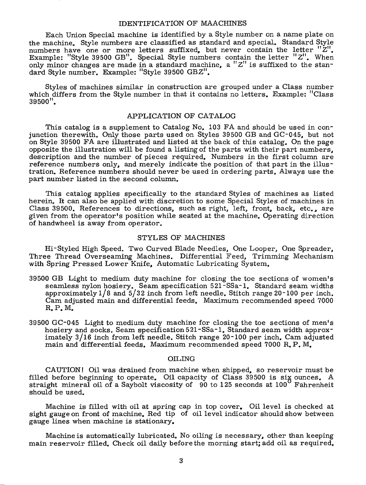
IDENTIFICATION
OF
MAACHINES
Each
the
machine.
numbers
Example:
only
minor
dard
Style
Styles
which
differs
39500".
This
junction
on
Style
opposite
therewith.
39500
the
description
reference
tration.
part
Reference
number
This
herein.
Class
given
of
handwheel
It
39500.
from
Union
Style
have
"Style
changes
number.
of
machines
from
catalog
FA
illustration
and
numbers
listed
catalog
can
also
References
the
operator's
is
Special
machine
numbers
one
or
more
39500
are
GB".
made
Example:
similar
the
Style
APPLICATION
is a supplement
Only
are
those
illustrated
will
the
number
only,
and
numbers
in
the
second
applies
be
specifically
applied
to
position
away
from
operator.
is
identified
are
classified
letters
Special
in a standard
"Style
number
parts
39500
in
construction
in
to
Catalog
used
and
be
found a listing
of
pieces
merely
should
never
column.
with
discretion
directions,
while
as
suffixed,
Style
numbers
machine,
GBZ".
that
it
OF
on
listed
required.
indicate
be
to
the
such
seated
by a Style
standard
but
are
contains
CATALOG
No.
10 3
Styles
at
the
back
of
the
Numbers
the
position
used
in
standard
to
some
as
right,
at
the
number
and
never
contain
11
a
Z"
grouped
no
letters.
FA
and
39500
parts
of
GB
this
with
of
ordering
Styles
Special
left,
machine.
on a name
special.
contain
the
is
suffixed
Standard
the
letter
under a Class
Example:
should
and
be
GC-045,
catalog.
in
the
that
parts.
of
Styles
front,
their
part
first
part
Always
machines
of
back,
Operating
plate
letter
11
Z".
When
to
the
stan-
number
"Class
used
in
but
On
the
numbers,
column
in
the
ill
use
as
listed
machines
etc.,
direction
on
Style
"Z".
con-
not
page
are
us-
the
in
are
Hi-Styled
Three
with
39500
Thread
Spring
GB
seamless
approximately
Cam
R.
P.M.
39500
GC-045
hosiery
imately
main
CAUTION!
filled
before
straight
should
be
Machine
sight
gauge
gauge
lines
High
Pres
Light
nylon
adjusted
and
3/16
and
differential
beginning
mineral
used.
is
on
front
when
Speed.
Overseam.ing
sed
Lower
to
medium
hosiery.
1/8
and
main
Light
socks.
inch
and
to
medium
Seam
from
feeds.
Oil
was
draiued
to
oil
of a Saybolt
filled
machine
with
of
machine.
is
STYLES
Two
Curved
Machines.
Knife,
duty
machine
Seam
5/32
inch
differential
duty
specification
left
needle.
Maximum
from
operate.
viscosity
oil
at
spring
Red
stationary.
OF
MACHINES
Blade
Automatic
Needles,
Differential
Lubricating
for
closing
Feed,
specification 5 21-SSa
from
machine
left
feeds.
521-SSa
Stitch
needle.
Maximum
for
closing
-1.
range
20-100
recommended
OILING
machine
Oil
capacity
cap
tip
of
of
in
oil
when
90
to
top
level
shipped,
of
Class
125
cover.
indicator
One
Looper,
Trimming
System.
the toe
-1.
Standard
Stitch
range
recommended
the
toe
Standard
per
speed
39 500
seconds
Oil
sections
20-100
sections
seam
inch.
7000
so
reservoir
is
at
100
level
should
One
Spreader,
Mechanism
of
women's
seam
per
speed
of
width
Cam
R.
P.
sia
ounces.
Fahrenheit
is
checked
show
widths
inch.
7000
men's
approx-
adjusted
M.
must
be
between
A
at
main
Machine
reservoir
is
automatically
filled.
Check
lubricated.
oil
daily
No
before
3
oiling
the
morning
is
necessary,
start;
other
add
oil
than
as
required.
keeping
Page 4
The
base.
which
ically.
oil
drain
It
is a magnetic
may
have
plug
entered
screw
screw
the
crank
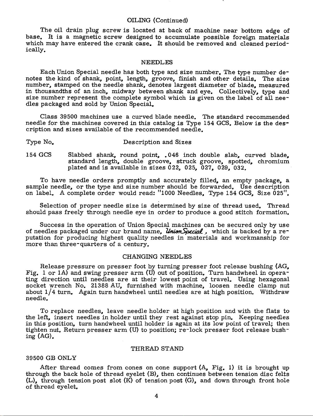
OILING
is
located
designed
case.
NEEDLES
(Continued)
at
back
to
accumulate
It
should
of
machine
be
removed
near
possible
foreign
and
bottom
materials
cleaned
edge
period-
of
Each
notes
the
number.,
in
thousandths
size
number
dles
packaged
Class
needle
for
cription
154
GCS
To
sample
on
label.
Selection
should
pass
Union
kind
stamped
represent
39500
the
and
sizes
Slabbed
standard
plated
have
needle
needle.,
A
complete
freely
Special
of
shank., point., length.,
on
of
an
and
sold
machines
machines
available
needle
the
inch.,
the
by
shank.,
needle
midway
complete
Union
use a curved
covered
of
round
length.,
and
is
available
or
of
orders
the
proper
through
type
·order
promptly
and
would
needle
needle
has
both
type
groove,
shank.,
denotes
between
symbol
Special.
in
this
the
recommended
Description
point,
double
groove.,
in
sizes
and
size
number
read:
size
is
determined
eye
in
and
shank
which
blade
catalog
and
•
046
022,
accurately
should
11
1000
order
size
number.
finish
largest
needle.
is
and
is
given
Type
and
diameter
eye.
The
154
needle.
Sizes
inch
struck
025,
double
groove,
027., 029.,
filled,
be
forwarded.
Needles,
by
size
to
produce a good
The
other
details.
of
Collectively,
on
the
standard
GCS.
slab.,
spotted.,
an
empty
Type
of
154
thread
type
number
blade.,
label
of
recommended
Below
is
curved
chromium
032.
package,
Use
description
GCS.,
Size
used.
stitch
formation.
de-
The
size
measured
type
all
the
and
nee-
des-
blade.,
025".
Thread
a
Success
of
needles
putation
more
than
Release
Fig. 1 or
ting
direction
socket
about
wrench
1/4
needle.
To
replace
the
left,
in
this
position.,
tighten
ing
39500
nut.
(AG).
GB
After
through
(L).,
through
of
thread
in
packaged
for
producing
three-
pressure
lA)
turn.
insert
Return
ONLY
thread
the
back
tension
eyelet.
the
quarters
and
swing
until
No.
Again
needles,
needles
turn
comes
hole
operation
under
our
highest
of a century.
on
presser
presser
needles
21388
AU.,
turn
leave
in
holder
handwheel
presser
from
of
thread
post
slot
of
Union
brand
quality
CHANGING
foot
arm
are
at
their
furnished
handwheel
needle
until
until
arm
(U)
to
THREAD
cones
eyelet
(K)
of
Special
name.,
needles
NEEDLES
by
turning
(U)
out
lowest
with
until
holder
they
holder
position;
on
cone
(B),
tension
machines
~
in
of
position.
machine,
needles
at
high
rest
against
is
again
re-lock
STAND
support
then
continues
post
materials
presser
point
of
are
position
at
(A.,
(G).,
and
Gan
be
.~
which
foot
Turn
travel.
loosen
at
high
stop
its
low
presser
Fig.
between
down
secured
is
backed
and
workmanship
release
handwheel
Using
needle
position.
and
with
pin.
point
Keeping
of
foot
1)
it
tension
through
only
by a re-
bushing
in
hexagonal
clamp
Withdraw
the
travel;
release
is
brought
disc
front
by
use
for
(AG.,
opera-
nut
flats
to
needles
then
bush-
up
felts
hole
4
Page 5
THREAD
STAND
(Continued)
39500
GC-045
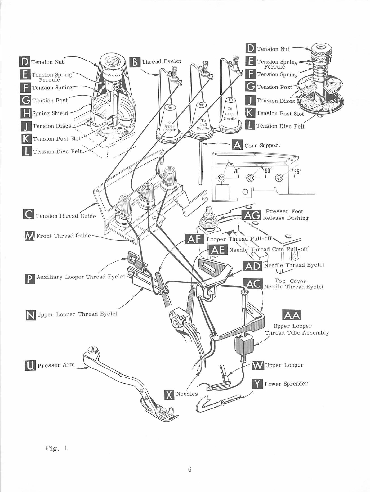
After
through
thread
eyeleto
Now
ed
through
Fig. 1 or
The
right
through
and
third
All
slot
(K)
Only
lA)o
Parts
threading
It
will
quence
dle
of
third.
thread
the
back
..
on
all
the
lA)
needle
the
upper
through
threads
in
tension
parts
are
of
Style
simplify
threading
Complete
ONLY
comes
hole
styles
upper
from
thread
hole
the
then
post
involved
placed
39500
of
the
holes
front
back
lower
continue
(G)
in
GB
the
threading
the
upper
the
from
thread
upper
(left
to
backo
is
threaded
to
hole
and
in
threading
their
or
full
cones
on
eyelet
looper
and
middle
Then
front
..
back
between
on
through
THREADING
relative
refer
looper
of
to
these
first
threading
cone
(B),
thread
through
through
second
to
fronto
the
front
are
shown
positions
Figo
machines
..
of
support
then
and
down
the
respectively)
the
lower
the
tension
through
tension
discs
thread
in
threading
for
lA
for
threading
to
the
right
one
needle
before
(A.,
Fig"
through
left
needle
of
tension
holes
thread
the
middle
(J).,
guide
(M).
clarityo
follow
second
proceeding
lA)
it
the
thread
thread
from
guide
hole
through
diagrams
Refer
of
Style
the
recommended
and
to
is
brought
front
is
hole
thread-
guide
back
to
(C)..
front
to
tension
(Fig" 1 and
to
Figo 1 for
39500
the
the
GC-045o
left
next
up
of
(C.,
fronto
first
back
post
se-
nee-
one.
Before
direction
turning
presser
tion.
Be
sure
tween
posts
for
tension
should
the
different
Turn
through
of
upper
front
auxiliary
of
assembly
thread
the
using
and
tube
threading
hooked
then
CAUTION!
from
tube
beginning
until
needles
foot
the
discs
be
positioned
handwheel
looper
thread
looper
(AA)..
assembly
wire,
end
insert
Be
thread
sure
assembly
to
release
threads..
(J)
threads
until
looper
thread
lead
the
(AA).
supplied
of
tweezers.,
upper
to
thread,
{X)
are
as
and
in
so
as
indicated
TO
point
thread
eyelet
pull-off
thread
through
looper
upper
swing
in
high
position.
bushing
they
(AG);
come
tension_post
the
tension
in
THREAD
of
upper
eyelet
(N)
(P)
from
(AF).
under
This
is
with
also
upper
easily
each
supplied
looper
thread
looper
TO
eyeo
THREAD
cloth
plate
and
from
slot
post
slot
Fig. 1 and
UPPER
looper
from
left
to
After
neck
pulling
of
accomplished
machineo
with
eye
is
under
NEEDLES
open
Release
swing
the
tension
(K)
in
will
lAo
LOOPER
(W)
is
back
to
righto
top
cover
Pull
each
from
the
..
turn
pressure
presser
thread
tension
be
at
all
the
front
NOTE:
up
upper
casting
by
thread
machine.
front
needle
handwheel
on
arm
guide
post
(G).
the
approximate
way
left.
..
then
through
Thread
looper
and
using
the
out
to
back.
threads
in
operating
pr~~sser
(U)
out
(C)
The
foot
of
posi-
are
tension
angle
Lead
thread
both
must
pass
thread
down
forked
bottom
Push
when
tube
through
end
of
down
passing
by
be-
eyes
in
tube
of
tube
..
Turn
position.
dle
thread
in
top
in
the
needle
handwheel
Insert
eyelet
cover
right
thread
both
needle
hole
eyeleto
in
(AD).,
thread
and
the
operating
needle
under
left
Thread
threads
neck
eyelet
needle
needles
direction
from
of
top
(AC).
thread
from
right
cover
The
5
until
to
casting
right
through
the
fronto
needles
left.,
needle
the
(X)
through
and
then
thread
left
are
BOTH
down
hole
at
should
of
the
their
eyes
through
be
threaded
top
highest
of
nee-
holes
cover
Page 6
(;]Tension
Nut
li]Tension
(ITensi
IJTension
[!]T
Fe
ension
I::Jspring
OT
ension Di
[I
Tension
n Tens ion
f!]
Front
Nut
on
Sprin
g
rrul
~
e
~
/
tv
Spring~~..-~~._,,,
Post~
Shield ....
Post
Disc Felt
Thr
-::--~
?;
scs·<
./
Slot.. --...
··.. ·.
ead Guide
~~~~
•---
~~Tension
IITension
[!]Tension
DTension
Ferrule
~~Tension
IITension
-FJ Cone Support
Sprin
g
~..-.!~~:i.l
Spring
Post
Discs
Post
Disc
..
_
Slott
·
'liiiii
··;;~~
Felt
·-
~-~~.,...
~~Auxiliary
~Upper
Fig
Loop
. 1
Lo
oper
er
Thread
Thread
Eyelet
Eyelet
£.t
Needle~
a Low
/
Upp
Thread
er
er
Looper
Tube
Ass
Spreader
embly
6
Page 7

m
Tension
Nut
gTension
OTension
[!lTension
ll)spring
n
Tension
(3
Tension
n
Tension
[i
Tension
~Front
Spring
Spring~~~~
Post
Shield
Discs · ....
Post
Disc Felt · ..
Thread
Thread
Fer~
Slot :
Gu
de
Guide
'"
..--· ...
~m~
Presser
Release
Foot
Bushing
~Upper
m
Presser
Looper
Fig. lA
Arm
Thread
Eyelet
_.....,,..Needle
~::;.J-,Iof"\"
-
~Upper
Top
Upper
Thread
Looper
Cover
Thread
Looper
Tub e
Eyelet
A3sembly
7
Page 8

The
tension
cure
proper
amount
nuts
(D,
stitch
of
tension
Fig. 1 or
formation.
on
1A).
THREAD
the
needle
Tension
TENSION
and
looper
on
threads
threads
should
be
is
regulated
only
by
sufficient
three
to se-
Sufficient presser
should
decrease
nut
screw
pressure
adjusting
(A).
locking
1 I 3 2
screw
be
maintained.
amount
(
A~
Fig. 2)
has a right
~
screw
VVith
nut
inch
to
(B).
Feed
eccentrics
loosening
presser
(C)
Set
been selected
chine,
It
eccentric
3954
of stitches
395
GC
B- 30
eccentrics
will
0 B-
00
GB
machine
differe
be
noted
70.
machine
is
ob
nti
1 I 16
cap
to
No.
Minor
tain
will
al
foot
Should
of
pressure
and
turn
hand
thread,
decreases
(B) h
so
as been
foot
that
inch
(D)
resting
its
from
against
used
produce
approximately
have been
on
the
39500
39540 B-100,
able
will
be
feed
numb
shipped
ers
when
be
shipped with
eccentric
PRESSER FOOT
pressure
it
be
on
adjusting
properly
under
the
locking
to
necessary
presser
screw
so
pre
ssur
on
throat
surface
top
feed
tightening
e.
set, tight
surface
nut
FEED ECCENTRICS
in the
395
00
GB
80
selected
GB
while
of
using
machine
the
part
that
to
produce
that
symbol
eccentric. Unless
above
with
No.
39540 B-60
.
PRESSURE
work uniform
to increase
foot~
loosen lock
(B).
Adjusting
increases
VVhen
pressure
en
plate~
is
approximately
of
adjusting
(C).
machine
stitches
approximately
that
the
of
the
differential
indicate
combination
main
ly
or
lock
nut
position
have
per
inch. On
part
number
approximately
feed
the
35
feed
otherwise
of
eccentrics
eccentric
Fig.
39500
stitches
of
the
per
main
eccentric
the
specified, the
.
The
and No.
2
GC ma-
inch
feed
is No.
number
395
39540
.
00
ene
rally
G
of
stitches
gree
and
produced.
direction
Following
6,
7,
8,
9~ 10~
Only
two
ordered
indicate
Before
guard, chip
ow this
l
VVith
center in
h
igh
position,
ove the
b
Style
bo
ve
395
the
11, 12, 13,
eccentrics
separately
number
assembling
guard,
suggested
throat
the
front
throat
00
GB
throat
the throat plate,
sening
clamp
scr
sp
eaking,
differential
Main (left
of
stretch
stitch number
14,
15, 16, 18, 20, 22 , 24, 26, 28, 30, 32, 34, 36, 40, 50,
are
supplied
.
To
order, use
of
stitches
A
SSE
MBLING AND AD
and adj
upper
knife
sequenc
SETT
plate
the need
plate
the need
pl ate.
move
ew (B).
ING
assembled
end
of
le
points
(Fig. 3)
le points should
To
align need
needle
Remove
of
feed
desired.
e:
THE
needle
for
driving
(ri
ght
hand) feed
material
being
eccentrics
with
each mac
No. 3954
Exampl
JUSTING SEVVING
usting
sewing
assembly,
NEEDL
in
slot
should
Style
E
position, needles
. VVhen
be
39500
be
le
or
set
arm
throat
plate.
hand)
ecce
feed
ntric
sewn, or
are
available
hin
e.
0 B
with a minor
e: 1139540 B-1
par
ts,
lower
knife
needles
set 15132
GC-045. For
set
7116 i
the
height
(A,
Fig. 3)
eccentr
is
sel
type
i c
ected
of
under
Additional
11
00
•
PARTS
remove
holder
assembly.
should
are
at
inch
a-
nch
a-
above
by loo-
determines
in
relation
operation
No.
3954
eccentrics
number
cloth
pl
ate,
Fig
number
.
0 B-
60,
70
may
s u
ffixed
Then,
. 3
to
~
fab
de-
4,
5
100.
be
to
ric
fol
~
-
8
Page 9

SETTING
At
bar
(C).
set the
using
spr
looper
eader deflec
Now
THE
this
point,
With
spreader
gauge
assembly
NEEDLE (Continued)
insert
lower
ting
spreader
point
No. 21225
the
differential (front)
1
18
lower
inch
spreader
at
from
G-
needles. Tighten
the
118
left
center
.
Do
feed
(A, F i
end
nut
dog
of
not
(B).
of
.
g.
its
left
have
4)
str
need
lower
into
oke
le,
,
Fig
between
F i
g.
. 4
the
6
rear
needle
SETTING
SETTING
Set
rear
high
as
possible
either
lower
deflect needle
Screw
guard. Make
guard
THE
Now, finish
As
spreader
should
until
surface another • 002
spreader
guard
(D)
ting,
guards
needles
Assemble
as
is
used
make
SET
lower
knife
(B)
and
LOWER
be
set
SETTING
is
springing
close
to
sure
and
differential
TING THE
needle
spreader
holder, but
is
used
sure there
lower
lower
moves
into
the
spring
front
as
possible
adjust
there
THE
guard
,
wi
tho
forward • 002
to set
spreader.
SPREADER
spreader
to
needle
forward
to • 004 inch
THE
needle
needle
and
is
feed
UPP
ut
or
still
the
is
the
r i
scar
from
FRONT
guard
off
to
set
front
no
dog.
ER
LOOPER
REAR
interf
no
interference
NEED
(A,
Fig
ering
movement
in
position
to • 004
rear
interference
adjustment.
ght, its
fs
(A,
rear
.
NEEDLE
(C,
backguard,
need
les
needle
LE
GUARD
. 5)
as
with
of
to
inch
.
nee
dle
poin
t
Fig
. 6)
guard
GUARD
Fig. 5). Whe
set
the
without
guard. Af
touchi
between
Fig. 5
front
ng.
ter
the
n
this
lower
needle
Screw
set
needle
-
Insert
its
holder
upp
er looper
Fig.
upper
and
permits
holder into
7
looper
(A,
Fig
. 7)
it
to
be
pushed
upper
the clamp holds the
pper
u
inch
beyond
When
u
pper
shank
Next,
its travel.
espect
r
di
mensions; dis
loop
er
throat
in
ch
on
loop
loop
er
the
looper holder
slightly
turn
Ch
to
needle
should
plate
Style
in
its
holder.
in
or
out,
er
s h
aft
upper
in
its
holder
holder
upper
back
eck
to
39500 GC-045
(Fig.
looper
sh
of
vertical
the handwheel
the dimensions
and
throat
t an
ce
from
be
approximately
point
of
9
Screw
or
turned
(if
not already
looper
so
that
7).
is
oul
d be
.
until
plate
centerline
looper
machine. (Fig. 8)
hold
the
at
the
set
of
the
5132
should
(B) hol
arou
nd
in
place
er
in the
shank
to position
looper
(Fig. 8)
extends
right
is
upper
of
left
inch
and
be
approximately
ds
upper
its
).
shaft. L
end
at
looper
and
needle
.
looper
shank
of
the
dis
. I
Screw
1 I
64
its
upp
er looper
left
point with
the
following
to
point
tance from
nsert
(C)
oca
to
1 I 3 2
stroke
end of
15
I 3 2
in
on
t e
,
of
Page 10

SETTING
THE
UPPER
LOOPER
(Continued)
NOTE:
looper
but
the set
plate
by
sents
so
checked
ing
Feed
veled
by
pin
the
the
is
moving
the
Fig.
Assemble
that
surface
surfaces
with
rotating
(D).
back
same
For
Style
point
with
ting
of
approximately
the
upper
dimensional
9
and
top
surfaces
by
sighting
with a straight
should
the
throat
fe
ed
This
pin
end
of
both
time.
395
00
respect
the
upper
looper
can
looper
per
of
align
tween
rub
and
end
and
set
of
across
plate
tilting
raises
feed
GB,
to
the
looper
7 I
16
inch.
setting
When
be
checked
is
eye
centers
the
upper
(Fig.
Check
upper
the
back
rotate
of
machine.
in
Figs.
SETTING
the
differential
the
feed
now
be
surfaces
adjusting
or lowers
bars
the
dimensional
center
If
holder
for
Style
the
moving
looper
9).
setting
looper
of
a
short
8
surfaces
feed
-
edge.
le-
at
of
point
resetting
(A,
39500
correct
quickly
to
the
on
the
to
and
upper
distance
Reset
and
9.
THE
feed
the
with
Fig.
setting
as
right,
right
and
avoid
needles
looper,
to
FEED
dog
all
setting
left
respect
is
8).
GC-045.
follows:
right
counterclockwise,
maintain
(A,
lay
of
is
also
to
necessary,
Figure
is obtained,
wh
en
upper
needle,
needle
interference
on
needle
pull
looper
DOGS
Fig.
in
the
the
upper
5 I 3 2
inch,
the
throat
do
so
8
repre-
it
As
upper
loo-
the
eyes
should
be
down
out
of
dimensions
10)
and
same
plane.
Fig.
stroke.
its
looking
suggested above
main
If
holder
from
feed
This
8
needles
slightly
left
dog
(B)
can
be
The
be
set
surface
throat
tilting
Now,
they
throat
Set
with
top
Replace
with
cutting
gonal
upper
feeding
level
first
plate.
adjusting
set
rise
above
plate.
chaining
of
head
knife,
at
appears
Screw
feeding
throat
low
edge
screw
so
surfaces
the
(E)
pin
in
3164
feed
plate
er
knife
flush
which
no
lateral
time
above
locks
place.
surfaces
inch
dog
(C)
when
holder
with
holds
should
feeding
the
feed
so
above
level
feed
SETTING
assembly.
throat
lower
adjustment
dog
THE
plate
is
at
LOWER
surface.
knife.
is
10
top
of
Lower
Lower
necessary
Fig.
its
travel.
KNIFE
knife
Adjustments
knife
when
(A,
is
width
10
Fig.
spring
are
of
11)
should
made
pressed
trim
with
is
changed
be
set
hexa-
against
.
Page 11

SETTING
THE
LOWER
KNIFE
(Continu
ed)
Fig.
holding
11
block
(H)
in
place.
Lower
ening
ket.
cloth
nut
knife
screw
Because
plate
(C)
holder.
Replace
(D),
Fig.
(F)
in
its
At
bottom
should
of
extend
lower
against the
edge.
After
trim,
This
screw
will
knife
(B)
latch
even
when
SETTING
upper
11)
most
of
its
knife.
upper
upper
(G)
simplify
may
and
screw
spring,
in
position,
clockwise
stroke,
not
less
The
knife
knife has
should
resetting
be
locking
(B)
screw
THE
knife
front
than 1/64
chain
and
be
secured
nut
also
serves
it
should
is
not
UPPER
assembly.
setting
position
cutting
guard
slightly
been
tightened
when
in
any
(C)
against
as latch pin
always
tightened
KNIFE
Clamp
nut
against
edge
inch
(J)
should
back
set
for
to
upper
position
support
be
against
(E)
to
of
below
from
proper
lock
knife
by
tight
brac-
for
locked with
lower
upper
hold
upper
upper
cutting
be
the
set
cutting
knife
clamp
knife.
knife
edge
down
width
upper
is
knife
replaced
-
the
of
.
Length
feed
eccentrics
actuates
eccentric
In
facing
Tighten
of
stitch
used.
main
(B)
(rear)
actuates
assembling
each.
nut
Be
(C)
securely.
is
determined
Outer
feed
the
feed
careful
SETTING
(left)
dog; while
differential
eccentrics
not
to
THE
by
eccentric
damage
,
STITCH
the
combination
the
inner
(front)
be
sure
shaft
To
change
(A,
LENGTH
Fig.
(right)
feed
hubs
or
eccentrics, remove
(C)
and
from
Turn
operating
til
key
is
toward
(F),
supplied
trics
be
necessary
slightly
washer
end
of
handwheel
direction
slot
in
front.
as
shown
during
shaft
eccentric
Using
with
and
to
extraction.
of
12)
dog.
are
key.
feed
nut
(D)
(E).
in
un
hooked
machine,
withdraw
move
Fig.
eccentric
reach
eccentr
behind
ics.
handwheel back
12
extractor
eccen
It
and forth
-
may
13
(H).
Fig.
from
Then
shaft
continue
13
(E),
it
may
as
originally
be
addition
helpful
suggested.
If
to
remove
11
eccentrics
to
removing
nut
(G)
are
nut
and
unusually
(C)
and
feed
tight
washer
driving
fitting, in
(D)
(Fig.
connection
Page 12

SETTING
THE
PRESSER
FOOT
Assemble
presser
(
front
foot
tant
presser
shaft
collar
(G) a
arm
and
must
that
the
foot
(H,
Fig. 14).
screws
nd then
to the left
collar
and
screws and
The
foot
the
collar
the presser
presser
foot
Adjust
that
presser
than
nut
inch
upper
(D).
free
the presser
me
nt
should
ed
with
nut
assemble
position.
the
into
back)
be
aligned with
bottom
can
(B,
shift
or
rig
lifter lever
(B)
arm
release
lifter
foot
looper
There
motion
foot
be
made
(F).
chip
guard,
presser
sewing
and
flat
position
on
front
of
the
be
realigned
To
move
Fig.
the
ht
clamp
secure
does
foot
as
required.
not
14)
screw.
the
bind
bushing
lever
can
will
should
of
begins
with
be
permit:
be
foot
to
stop
lifter
rise.
screw
Re-assemble
turn
handwhe
foot
to
throat
edge
presser
with
the
shaft, loosen
and
clamp
lifter
arm
(A,
shaft.
and
is
screw
raised
then
from
lever
This adjust
(E)
the
presser
and
set
plate.
of
needle
foot
be
throat
screw
lever
shaft
Re-tighten
Fig. 14)
Be
sure
rise
when
unlocked.
(C)
no
higher
lock
1/ 16
to 1/8
before
and
lock
chip
el
guard,
until
arm. With needle
the
presser
The front
hole
flat
plate
slots
on
in
the
edge
throat
throat
by
shifting
so
the
-
-
upper
fabric
knife
guard
assembly
foot
of
Fig.
in
high
to
needle
plate.
plate.
the
14
and
reaches
position,
align
hole
It
foot
cloth
needle
in
is
also
If
necessary,
lifter
plate.
its
swing
holes
presser
impor
lev
highest
-
er
To
Be
sure mac
(either
let
Op
forms
material,
FOR
remaining
(N,
era
While
39500
About
Fig
Figs.
te
machine
and
. 1
moves
and
sewing
GC-045
60%
40%
needle thread
tacts
stitch
the
FOR
needle
The
eye
is
obtained
complete
39500
GB
Usually,
stroke,
thr
eads tend
With
the
the
thread
needles
needle
above
thread
conditions
hine
or
Fig. 1A).
1
or
1A)
slowly,
off the
sew
slowly.
on
of
needle
is drawn on
eyelet
thread
let
.
is
adjusted
(AD
with
speed
all
range.
needle
should
to
pull
at
bottom
pull-
.
is
thr
With
about
without
tongue freely.
NEEDLE
material,
thr
the
,
Fig.
correctly
the
least
thr
ead
be
just
down
of
off
slightly
stroke,
(AE)
STARTING
eaded
according
thr
ead
hori
zontal and
presser
THRE
check
ead
is
drawn
upstroke
1A)
so
amount
is
drawn
tight
enough
if
position
draws the
TO
OPERATE
to
tensions
foot
Swing
AD
CONTROL
needle
thr
from
.
With
that
needle
in
its
front
of
needle
on
needle
to
excessive
needle
proper
diagram
ligh
back
in
presser
ead
cones
needle
thread
to
thread
feed
thread
thread
amount
t,
set
in
place,
control
on
at
back
down
chain
for
your
upper
its
front
to
make
foot
into
as
follows:
needle
bottom
cam
pull-off (AE) just
position
tension
stroke.
off
stitch
is
pulled
eyelet
of
(AD,
needle thread
style
looper
to
back
sure
position,
down
of
stroke,
when
when
At
tongue.
on the
Fig.
of
thread
location.
that
stroke.
the
sewing
top
of needle
up
1)
to
machine
eye
cha
in
insert
The
position
con-
desired
over
Needle
stroke.
so
that
satisfy
-
12
Page 13

UPPER
LOOPER
THREAD CONTROL
During
or
Fig.. 1A)
of
looper
as
looper
FOR
looper
let
break
FOR
per
39500
If
upper
thread
is
raised
excessively--even
39500
If
upper
thread
forward,
amount
of
CAUTION!
carrying
If
the
butted
seam
FOR
appearance.
results
39500
Raising
causes
stroke
raised
ing
to
the
less
and
in
looper
insure
purl
and
is
needle
will
draw
thread
thread
GC-045
looper
eyelet
too
GB
looper
eyelet
the
looper
looper
Do
not
high
tensions.
POSITIONING
purl
is
when
GC-045
and
thread
causes
brought
thread
a
flexible
desired.
down
upper
is
drawn~
pull-
off
thread
(N~
high
and
thread
(N~
Fig.
thread
thread
try
to
at
the
If,
however,
opened.
bringing
to
be
the
purl
too
far
breakage.
chain,
stroke~
reaches
forward
looper
upper
thread
looper
its
has a loose
Fig.
1A)
forward
moved
too
with a minimum
has
loose
1)
forward
will
tend
tension
applied.
obtain a tight
top
THE
edge
PURL
of
the
the
the
upper
pulled
from
to
form
forward,
however.,
With a reasonable
the
looper
stroke
through
thread
most
rearward
appearance
and
far
forward~
amount
appearance
slightly.
to
break
looper
TO
OBTAIN A FLAT
garment.,
purl
is
looper
the
cones
more
on
thread
of
looper
the
will
raise
of
in
the
If,
excessively-
thread
the
under
the
thread
as
the
the
top
the
thread
amount
eyelet
thread
tension..
have
almost
position.
in
the
slightly.
the
looper
looper
seam~
however.,
...
appearance
seam
can
edge~
eyelet
looper
of
the
becomes
of
should
pull-off
When
all
seam~
If~
move
however,
thread
thread
tension
move
the
eyelet
even
with a minimum
SEAM
be
opened
a
less
(N~
Fig.
travels
edge.
too
looper
be
adjusted
(AF~
normal
slack
will
the
on
the
flat
1A)
to
the
If
the
tight,
thread
Fig.
amount
taken
the
the
upper
eye-
tend
up
to
applied.
upper
is
too
seam
loo-
far
by
into a near
and
tighter
forward
top
of
its
eyelet
is
result-
tension
to
position
1
FOR
39500
Moving
pulled
purl
ever,
off
sure
from
to
the
the
uniformity,
desired.
FOR
39500
The
terial
being
possible
seam
FOR
and
39500
The
insure
uniformity
tension
coming
chine.
tained
machine.
form
threads
throat
needle
without
low
needle
disc
slack
All
by
varying
GB
the
needle
the
cones
more
on
become
plate
tongue.
the
THREAD
GC-045
thread
sewn.
In
causing
enough
GB
threads
of
stitch.
felt
(L,
between
controlling
the
thread
as
the
the
top
needle
TENSIONS
tension
general.,
the
to
prevent
and
Fig.
1)
these
tension
tensions
needles
of
slack
eyelet
the
at
travel
edge.
the
(AD,
top
With a reasonable
thread
eyelet
should
WITH
required
upper
needle
looper
looper
NOTE:
should
tension
settings
Tension
only
at
is a function
looper
threads
thread
thread
be
pads
and
to
the
tension
Fig.
to
the
If
the
eyelet
of
the
minimum
be
RESPECT
thread
to
be
breakage.
tensions
applied
enough
the
insure
discs,
1)
back
top
of
their
is
moved
stroke
and
needle
adjusted
TO
of
needle
tension
pulled
too
should
to
the
threads
to
prevent
tension
discs
uniformity
which
causes
stroke
back
the
thread
to
position
STITCH
thread
should
far
over
be
set
the
mounted
of
stitch
are
less
chain
thread
and
too
will
causes
far,
tension
the
and
be
set
as
the
top
at a minimum
at
the
thread
threads
from
on
should
mounted
not
to
purl
the
high
of
the
be
on
to
be
the
how-
feed
in-
as
rna-
as
the
to
stand
be-
ma-
ob-
the
13
Page 14

14
Page 15

The
Styles
parts
39500
illustrated
GB
and
on
39500
the
preceding
GC-045,
but
page
not
and
used
described
on
Style
on
39500
this
FA.
page
represent
the
parts
used
on
Parts
39500
Use
shown
GB
Catalog
Reference
indicate
Ref.
No.
1
2
3
4
5
6
7
8
9
10
11
12
13
14
15
16
17
18
19
20
21
22
23
24
25
26
27
28
29
30
31
32
33
34
35
36
37
38
39
40
41
42
43
44
45
46
in
and
39500
No.
numbers
they
are
39552
22596
50-774
154
39563
39563
39592
39592
39592
39592
39520
39520
39530
22738
39597
22768
39530
22738
39530
39530 s
39556
39505
39526
39505
22797 A
39505
39526
39524
39524
39524
39528
39525
39525
29477
51-228
39516-625
39516-626
39516-627
30-92
C067
40-46
258
39541 A
29477
22587 M
22596
39540
39540
39540
39540
22569 D
39563
39563
39501
39501 D
39578
39578
39563 R
39563
39560
phantom
GC-045.
103
FA
that
components
Part
No.
G
E
Blk
GCS
p
G
AE-1
AE-1
AE-2
E
AB
AC
p
AB
B
G
R
J
E
AC
AC
AB
AB
AB-1/8
AB-5/32
AC
AC
J
H
KJ
Blk
Blk
E
JN
G
B-100
B-60
B-70
B-30
N
H
DD
TB
u
X
B
views
for
are
and
all
parts
inside a bracket
of a complete
Needle
Needle
Needle
Needle
Needle
Looper
Looper
Pad,
Presser
Presser
PresserArm-----------------------------------------------
Chaining
Differential
Main
39500
Screw,
Main
Differential
Throat
Throat
Throat
Throat
Needle
Needle
Crankshaft
Main
Main
Differential
Differential
Screw,
Needle
Needle
Cloth
Cloth
Chip
Chip
Top
Top
Lower
bearing
not
no
reference
illustrated
or
box
part
or
or
described
on
the
picture
assembly.
numbers
here.
plate
are
common
and
Description
Driving
Screw,
Stop
Arm-----------------------------------------
for
Pin,
needle
for
needle
driving
arm
------------------------------------
--------- ----
----------------------------------------------------
Thread
Thread
Tension
Tension
Tension
for
Chip
Screw,
Stitch
Screw,
Hinge
Screw,
Chain
Chain
Feed
tension
Foot,
Foot,
Pull-off,
Cam
Spring,
Spring,
Spring,
post
for
for
Pull-off,
mounting
Style
Style
for
for
for
for
39500
39500
Style
for
Styles
Style
Style
bracket
GB
GC-045
39500
Style
39500
39500
GB--------------------
39500
39500
GB,
GB
--------------------
GC-045
-----------------------
----------------------------
------------------------
Guard---------------------------------------------
for
chip
guard
-----------------------------------
Tongue,
for
stitch
marked 11EK
tongue
11
and
-
----------------------------
hinge
spring------------------
Spring-------------------------------------------
for
chain
Shield,
Shield,
Feed
Feed
Dog,
Dog,
shield----------------------------------
for
presser
for
presser
20
teeth
Dog,
22
marked 11AM
per
teeth
foot
foot
11
, 22
inch,
per
No.
No.
inch,
teeth
39520
39520
for
Style
for
per
GC-045--------------------------------------------for
chaining
Feed
Dog,
Feed
Plate,
Plate,
Plate,
Plate,
Guard,
Guard,
and
Vent
Plug---------------------------------------------Needle
Needle
Needle
\Vood
Cork
Bearing,
Bearing,
Bearing,
Plug---------------------------------------------
Plug---------------------------------------------
feed
dog,
for
Style
marked 11AG
Dog,
rubber,
11
,
marked 11AX-1/8
marked 11AX-5/32,
marked 11AV
marked 11AY
11
,
for
11
,
for
rubber,
for
11
,
Style
for
for
Style
Style
39500
for
Style
Style
39500
39500
Style
39500
39500
39500
rear----------------------------------------front-----------------------------------------
Needle
Driving
.0625
.0626
.0627
Arm
Crank
inch
diameter---------------------
inch
diameter---------------------
inch
diameter---------------------
Assembly-----------
\Vasher-----------------------------------------------Nut---------------------------------------------------
Feed
Needle
Screw,
Screw,
Feed
Feed
for
Thread
Thread
Plate,
Plate,
Guard,
Guard,
Cover
Cover
Spreader,
Driving
Driving
Driving
needle
Needle
Needle
Driving
for
for
Feed
Feed
Eyelet,
Eyelet,
for
Style
for
Style
for
Style
for
Style
Eccentric
Arm
needle
needle
Eccentric,
Eccentric,
Driving
Driving
thread
for
for
39500
39500
39500
39500
Thread
Thread
for
Styles
Key
Crank
and
driving
driving
for
for
Eccentric,
Eccentric,
-------
Style
Style
----------------------
Connecting
arm
connecting
arm
crank----------------39500
39500
for
Style
for
Style
eyelet------------------------------
Style
39500
Style
GB---------------------
39500
GC-045-----GB-----------------------------GC
-----------------------------GB-----------------------------GC
------------------------------
Eyelet,
Eyelet,
39500
for
for
GB,
Style
Style
GC-045
39500
39500
to
Styles
have
indented
----
---
GC-045
GC-045
-----------
-----------
----------------
AC--------------AB---------------
39500
Style
inch,
GC-045
39500
for
Style
GC-045-----------
39500
GB
GB------
------------GB-1/8
GB-5/32
GC-045
GC-060
Rod
Assembly---
rod
-----------
-----------
---------
GB-------------GC
--------------
39500
GB--------
39500
GC
--------
-----------
GC-045------GB-----------
----------------
39500
descriptions,
-----
--
---
GC-045-
-------
------
FA,
Amt.
Req.
1
1
1
2
1
1
2
1
1
1
1
1
1
1
1
1
1
1
1
1
1
1
1
1
1
1
1
1
1
1
1
1
1
1
1
28
28
28
1
1
1
1
1
1
2
1
1
1
1
1
1
1
1
1
1
1
1
1
1
1
15
Page 16
16
Page 17

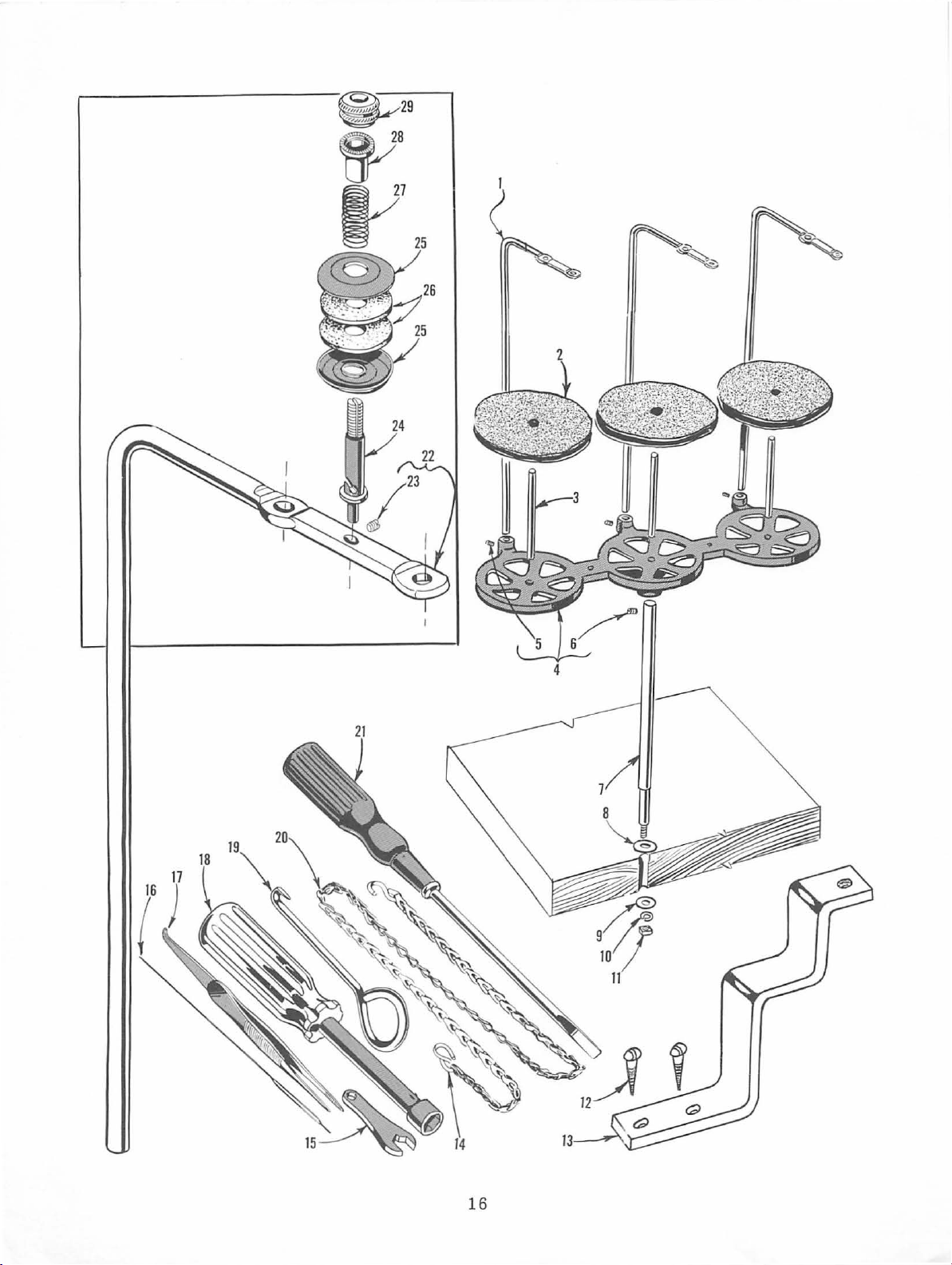
THREAD
STAND
AND
MISCELLANEOUS
TOOLS
Ref.
No.
9
10
11
12
13
14
15
16
17
18
19
20
*21
t
t
1
2
3
4
5
6
7
8
Part
No.
21113
21104
69 s
21130
22650
22650
21104
652 J-24
652
WA9A
651
SC333
39592
660-264
116
39599
660-240
21388
21227
421
21202
28604
39595
F
v
W-3
CB-4
CE-6
AA
J-16
A-16
A
w
A
AU
BF
D-34
R
Description
For
Style
Thread
For
Styles
Pad,
Spool
Cone
Thread
Washer------------------------------------Washer-------------------------------------
Lock
Nut
Wood
Tension
"S"
Wrench~
Threading
Thread
Socket
Cam
Treadle
Screwdriver,
Container
Isolators,
for
Support-------------------------------Screw,
Screw,
Washer
----------------------------------------
tableboard---------------------------------
Hook
eccentrics---------------------------------
Extractor
overall------------------------------------
39500
Stand
39500
thread
Pin--------------------------------
Stand
Screw,
Post
for
~
for
Wire
Tweezers
Wrench,
Chain~
of
rubber----------------------------
GC-045
Eyelet
GB
and
cone
for
thread
for
thread
Rod
-----
-------------------------------round
Bracket,
treadle
9/3 2 inch
------
----------------------------
for
---for
presser
3/16
Oil~
inch
16
Only
and
Support
GC-045
-------------------------
stand
stand
-------
head
for
chain-------------------
nuts
--
3/8
-----
ounces,
eyelet-----------rod
#9 x 5/8
mounting
---
--------
inch
nuts
---
---
foot
diameter,
Spec.
Rod----------....
--------------
- -
----
---
-------
inch
long-----
on
--------
------
holding
---lifter
9
---
------feed
---
--------
---------
3/8
inches
83----------
--
....
---
--
Amt.
Req.
3
3
3
1
3
1
1
1
1
1
1
2
1
2
1
1
1
1
1
1
1
1
4
t
22
23
24
25
26
27
28
29
21113 G
22565
39592
39592
51292
Not
Not
c
D
109
E
107
108
furnished
shown
F-1
on
For
Style
Thread
Screw,
TensionPost-------------------------------Tension
Tension
Tension
Tension
Tension
with
picture
machine.
plate
Stand
Disc
Spring
Spring
Post
Post
..
39500
for
GB
Only
Eyelet
(inverted)-----------------------
Pad,
-----------------------------Ferrule
Nut
and
Support
tension
...
post
felt
---------------------
------------------------
---------------------------
17
Rod
----------
------------------
3
1
3
6
6
3
3
3
Page 18

Helpful,
ci
ent
types
machine
Promotion
Sales
esting, ill
obligation
authoritat
sewed
ustrated bulletins that
are
of
equ
artic
Department.
the foll
ive
information
ipm
ent for
le is available
owing:
on
mak
ing virtually
from
Among
Union
the
are available
the
most
Special's
many
without
effi-
any
inter-
HERE
ARE
HELPFUL
No. 240,
No.
No.
N
o.
No .
N
o.
No.
No.
No. 259,
No.
No.
No.
No.
No.
No.
No.
No.
No.
No.
No.
No.
No.
No. 730, "MCS Automatic Dual
No.
No.
No.
No.
"Columbia
ing
N
o. 1500, "Alterat
"Men's,
249,
"Rainwear"
250,
"Men's
251,
" Service
252, "Me
253, "Overalls,
254, "Men's K
256, "Knit
"Men's
260,
"Work
262
, "
Bags"
263,
"Men's Cloth
264,
"Men's
265,
"Women's
266, "Women
26
7,
"Corsets,
268,
" Ch
269,
"Mattresses,
Upholstery"
271, "Awnings, Canopies,
273, "Curtains & Drapes"
610, "Kiipp-it"
710,
"MCS
Hemmer"
740, "MCS
750,
"Fusing Pre
1100, "Lewis
sti
110
5,
"Button
Machine
Wome
Dress
Shirts
n's
Shorts
nit
Outerwear"
Sports
Gloves "
Cot
ton,
Bur
Women's,
's Wear
Girdles, Br
ild
ren
's Wear"
ForMat
Automat
Blindstitch,
tch,
Machines"
Sewers-Ti
Blindstitch,
s"
ion
n's, Children's
Shirts"
and Pants"
and Pajama
Coveralls,
Underwear
Shirts"
lap,
Jut
ing"
Wear"
And
Slip
Covers,
ion
ic
sses
"
Saddle
Dep
artment
Children's Jackets"
Unit"
Rib-Knit
Footwear"
s"
and
Dungarees"
"
e, a
nd Multiwall
High
Fashion"
assieres"
Furniture
T~nt
s,
Tarp
Underfront
Cuff
Chains
titch,
cket Tackers"
Stitch,
and
Machines
Paper
s"
Shir
Machine
Lock·
Tie
Clos-
"
BULLETINS
TO
HELP
SEWING
t
"
and
YOU
CATALOGS
SOLVE
PROBLEMS
®
Page 19

BOOST
PRODUCTION
WITH
WORK
UNION
THESE
AIDS
SPECIAL
FROM
PNEUMATIC
conventional
scissor-action mechanism
positive
AIR
FAB
signed
remove
to
knit
materials
ar
ea.
Style
CHAIN-CUTTER
Class 39500 and 39600 is a
cui.
Style
2899 A-1
RIC
Cla
ss 39500
cur
ls
as
2899 B-1
UNCURLE
from top and
machines,
fabric passes thr
for
that
R-This
bottom
-fo
r use on
makes a
u
..___
unit,
uses air
plies
ough
durab
\ '
sewi
clean
~·
de-
jets
ol
flat
le
ng
PNEUMATIC
operated
machines
simply
CHAIN
small
for
36200 Flat
foot
allows
by kne
CUTTER
pneumatic
installation
seamers.
FOOT
lifter
the
e-touchi
-
cha
as an
Style
for
use
operato r
ng
an
The
above
in
cutter
accessory
2899A-6
LIFTER
on
to
actuating
photo
that
.-
:
~
- The a
Class
raise
shows
is
unit
on
ir-
39500
t
he
foot
switch.
the
available
Class
KNIFE
GRINDER
type knives,
nates defective
is
simple
sharpens
and easy
garments
straight
to
caused
opera
by
dull
or
te,
®
u
FIHEST
OUALITY
M A
cHINE
wheel
insuring
ELECTRON
to
move
be
tter
IC NEE
DLE
the
needle
control, uniform quality and incre ased
up
or
d
POSJTJONERS
own
...
AMCO
angle
elimi-
knives.
th is all
HEAT
unit (arrow)
oil
temperature
quires it.
elimi
nate
ows the
production.
DISPELLER
is
Style
the
necessity
operator
- Union
an
effective means f
where
heavy duty service
2899 E
-1
of
keep
reaching
both
to
Special's
hands
or
f
or
on
auxiliary
reducing
the
hand·
the
work,
re·
Page 20

WORLD'S
FINEST
QUALITY
*
~'
I~
INDUSTRIAL
SEWING
MACHINES
UNION SPECIAL
facilities
aid
throughout
you in
equipment
Special
tory
promptly
tion,
serve
ATLANTA, GA.
BOSTON, MASS.
CHICAGO,
DALLAS,
LOS
ANGELES,
NEW YORK,
PHILADELPHIA,
representatives
trained
and
there
you
.
ILL.
TEXAS
N.
maintains
the
selection
for
your
and
are
efficiently.
is
a Union
C~eck
with him
CAL.
Y.
PA.
sales
and
the
world. These offices will
of
the
right
particular
and
able
Special
operation.
service men
to
serve
Whatever
Representative
your
your
today.
MONTREAL,
TORONTO, CANADA
BRUSSELS,
LEICESTER,
LONDON, ENGLAND
PARIS,
STUTTGART,
FRANCE
service
sewing
Union
are
fac-
needs
loca-
to
CANADA
BELGIUM
ENGLAND
GERMANY
400
Representatives
MACHINE
N.
FRANKLIN
industrial cit
and
ies
ST.,
distributors
throughout
COMPANY
CHICAGO,
in
the
all
important
world
.
ILL.
60610
'
 Loading...