

Page 1

®
INDUSTRIAL
SEWING
FINE
ST
39
39
395
39S
395
395
ST
QUALITY
YLES
500FS
500FT
00FU
00G
00GL
00GT
D
LEWIS•
COLUMBIA
MACHINES
395
00J
P
395
00MM
CATALOG
No.
103FS
SECOND
EDITION
CLASS
HI-STYLED
HIGH
SPEED
WITH
INTERMITTENT
DIFFERENTIAL
39500
OVERSEAMERS
FEED
CHICAGO
Page 2

Here
are
Oil
for
Sewing
roleum
mended
machine
ro
leum
whit
1.
For
mount.
roleum
high
mitter
3. Where
used.
UNION
SPECIFICATION
Viscosity S.S.U.
Flash
Pour
Color
Neutralization
Viscosity
(D
Compounding
Copper
*
An
line No. 1 75-225 1 75-225 1 75-
*Used with
Specifications
Union
Special
Machines
Specification
oil,
viscosity
for
all
s.
Specification 175 specifies a high
oil, viscosity
e or wi
th a maximum
use
where freedom from
Specification 87 specifies a high
oil,
viscosi
Specification
quality
grease
s.
It
is
similar
No.
3 grease
SPECIAL
(Min.)
(Max .)
A.S.T.M.
Index
& D
Min
.) 85
Corrosion
Buna N
174
spec
100
oiling
ty
sec
applications
100
seconds at
A.S.T.M . co
300
seconds at
100
specifies a general purpose
for
use
to
in ball bearings and transcommercial
is
not
obtainable,
NO . 174 175
at
100°F
(Max.)
No. (Max.) 0.
(Max
Rubber "O"
90-125 90-
.)
ifie s a high q
ond
s at
100°
on hig h speed
oil
staining is para-
100°F.
N.L.G
350
20 20
10
None
lA
Retainers
350
3
0.
None
100°F
lor
.I.
No. 2 may
125
10
85 85
lA
ualit
y pet-
F. Recom -
quality
quality
pet
., water
number
pet
, grease No.
87
300-350
350
20
1 3
0.10
None
lA
-
of
·
be
225
NOTE
meeting above classification
essential. These
These additives
and
separate.
NOTE
shall
1: The
1.
Oxidation
2.
Rust
3.
Lubricity
4.
Anti-oxidant
Film
5.
not
removable
2:
Oil
not
be
1.
Extreme
2. Tackiness
3. Lead soap
4. Detergents
f!
NUT
OUAUTY
use
of
non-
corrosive additives
may
include
inhibitors
inhibitors
additives
s
strength
s c
used
additives
must
be
completely soluble in
by
wick
onta
ining the
at any
time
pressure additives- corrosi
or
adhesive additives
additives
CORPORATION
is
:
feeding
following
:
desirable
nor
type
in
but
the
shall
additive
ve
®
oil
not
oil
they
..
s
s
Page 3
Catalog
INSTRUCTIONS
FOR
No.
103
FS
ADJUSTING
39500
39500
39500
39500
FS
FT
LIST
FU
GD
Second
Class
AND
OF
39500
Styles
OPERATING
PARTS
39500
39500
Edition
39500
39500
GL
GT
JP
MM
October,
197
3
Union
Rights
Copyright
By
Special
Reserved
1967
Corporation
in
All
CORPORATION
INDUSTRIAL
Printed
SEWING
CHICAGO
in
3
MACHINES
U.S.
Countries
A.
Page 4

IDENTIFICATION
OF
MACHINES
Each
the
machine.
numbers
ample:
minor
Style
"Style
changes
number.
Styles
which
differs
39500".
This
herein.
Class
given
of
handwheel
It
39500.
from
Hi-Style
Four
Thread
Mechanism
39500
FS
and
intermittently
dresses.
press
separate
length.
mm).
Maximum
Union
Style
have
one
39500
are
Example:
of
machines
from
catalog
can
also
References
the
operator's
is
away
High
Speed,
Overseaming
with
Single
aprons.
controlled
top
Seam
Stitch
recommended
Special
numbers
or
more
FS".
made
similar
the
Style
applies
be
applied
from
One
Spring
needle
Pressed
three
gathering
lingerie.
tandem
and
bottom
specification
range
8-20
machine
are
is
classified
letters
Special
Style
in a standard
"Style
39500
in
number
APPLICATION
specifically
with
to
directions,
position
operator.
STYLES
or
Two
Machine.
Lower
thread.
or
smocks.
intermittent
plies.
504-SSa-1.
per
inch.
speed
identified
as
suffixed.
numbers
machine.
FSZ".
construction
in
that
it
OF
to
the
discretion
such
while
Curved
seated
OF
MACHINES
Blade
Intermittent
Knife.
medium
shirring
nightgowns
differential
Gathering
Standard
Cam
6000
R.P.M.
by a Style
standard
but
never
contain
a
"Z
are
grouped
contains
CA
TA
LOG
standard
to
some
as
right.
at
the
Needles.
Differential
Automatic
to
heavy
on
woven
ratio
up
adjusted
number
and
contain
the
II
is
suffixed
on a name
special.
the
letter
Standard
letter
"Z".
to
under a Class
no
letters.
Styles
Special
left,
front,
machine.
Two
Example:
of
machines
Styles
Operating
Looper.
of
back.
Feed.
Lubricating
duty
and
knit
and
similar
feed.
Slotted
machine.
System.
materials
garments.
presser
to 3 to 1 depending
width
main
of
and
seam
1/8
differential
plate
"Z".
When
the
standard
number
"Class
as
listed
machines
etc
••
direction
Three
Trimming
for
seaming
such
foot
on
stitch
inch
(3.17
feeds.
on
Style
Ex-
only
in
are
or
as
Knee
to
39500
FT
and
dresses.
press
pressure
on
inch
feeds.
39500
FU
and
dresses,
press
grooved
shirring.
fi
cation
8-2 0
ed
39500
GD
intermittently
ses.
controlled
su
re
stitch
needle
and
Single
needle
intermittently
aprons.
controlled _tandem
stitch
(4.
plate
length
76
att
';-
mm).
Maximum
Single
needle
intermittently
aprons.
controlled
for
1 / 8
Gathering
504-SSa-1.
per
speed
Two
inch.
5500
Cam
R.P.M.
needle
gathering
aprons.
lingerie.
tandem
plate
attachment
length.
17
/ 64
Seam
inch
differential
three
gathering
lingerie.
intermittent
a c
lmient for
Seam
Stitch
specificatT<5il"
range
recommended
three
gathering
lingerie.
tandem
inch
cord.
ratio
Standard
adjusted
four
thread.
or
smocks.
intermittent
for shirring.
specification
(6.
75
mm).
feeds.
Maximum
thread,
or
smocks.
medium
shirring
shirring
nightgowns
--.?
ifferential
.!
504-SSa-1.
8-20
thread.
or
smocks.
intermittent
Independent
up
to 5 to 1 depending
main
shirring
per
speed
medium
shirring
width
and
medium
inch.
6000
nightgowns
differential
swing-out
of seam
differential
to
on
woven
nightgowns
differential
Gath
512-SSa-1.
Stitch
range
recommended
to
heavy
on
woven
Gathering
Cam
R.P.M.
to
heavy
on
woven
3/16
heavy
duty
and
and
similar
feed.
er ing r
atio
Standard
8-20
speed
duty
and
and
feed.
ratio
machine.
knit
similar
Independent
up
Standard
adjusted
duty
and
and
feed.
main
machine.
knit
similar
Presser
pressure
on
stitch
inch
feeds.
length.
(4.
76
Maximum
machine.
knit
materials
garments.
Independent
up
to 3 to
width
per
inch.
6000
for
seaming
materials
garments.
such
Knee
swing-out
to 3 to 1 depending
width
materials
plate
mm).
of
seam
and
differential
for
seaming
garments.
foot
attachment
Seam
Stitch
3/16
such
Knee
bottom
for
speci-
range
recommend-
for
swing-out
1 de
of
seam
Cam
seaming
such
as
Knee
pending
from
adjusted
and
dres
press
pres
left
main
R.P.M.
as
as
-
-
on
4
Page 5
STYLES
OF
MACHINES
(Continued)
39500
39500
39500
GL
intermittently
ses.
controlled
sure
stitch
needle
and
GT
and
and
press
curler
shirring.
fication
Stitch
mum
JP
adjusted
weights
long
versed
width
inch.
6000
Two
needle
gathering
aprons,
plate
length.
17 / 64
differential
Single
intermittently
silk
fabrics
controlled
stitch
range
recommended
Single
of
straight
or
of
Cam
R.P.M.
lingerie,
tandem
attachment
Seam
inch
needle
tongue.
Gathering
504-EFe-1
10-20
needle
intermittent
flat,
seams
forward
seams
adjusted
four
intermittent
specification
(6.
7 5
feeds.
three
gathering
where
tandem
ratio
inverted.
per
speed
three
differential
warp
3/32
and
are
differential
and
main
thread,
or
smocks,
for
mm).
Maximum
a 3 / 32
intermittent
Independent
inch.
thread.
ribbed
necessary.
1/8
and
medium
shirring
differential
shirring.
Stitch
thread.
or
inch
up
to 3 to 1 depending
Standard
Cam
6000
R.P.M.
feeding.
inch
differential
to
heavy
on
woven
nightgowns
Gathering
512-SSa-1.
range
recommended
medium
shirring
(2. 38
swing-out
adjusted
light
feed
knit
(2.38
on
mm)
differential
width
to
medium
for
cotton,
Thumbscrew
Seam
and
feeds.
duty
and
and
similar
feed.
8-2 0 per
to
all
main
seaming
wool,
Independent
ratio
Standard
speed
heavy
types
turned
feed.
pressure
on
of
and
specification
3.17
Maximum
machine,
knit
materials
up
width
inch.
5500
duty
of
down
Presser
stitch
seam
differential
duty
machine,
and
trimming
rayon
feed
which
mm).
for
seaming
such
garments.
swing-out
to 5 to 1 depending
of
seam
Cam
R.P.M.
machine,
cotton,
hem
plate
length.
3/32
and
504-SSa-1.
Stitch
recommended
adjusted
dacron,
is
desired.
foot
attachment
inch
with
silk
fabrics
allows
range
as
dres
Knee
for
has a short
Seam
(2.
feeds.
all
press
pres
from
seaming
rayon
speci-
38
Maxi-
operator
types
where
either
Standard
8-30
speed
and
-
-
on
left
main
Knee
for
mm).
and
re-
per
39500
fiiled
straight
should
gauge
lines
main
It
have
MM
and
dresses,
press
pressure
on
stitch
inch
feeds.
CAUTION!
before
mineral
be
Machine
on
front
when
Machine
reservoir
The
oil
is a magnetic
entered
Single
intermittent
controlled
(4.
76
Maximum
used.
is
machine
is
drain
the
needle
gathering
aprons,
tandem
plate gtachment fo
length. Seam
mm).
beginning
filled
of
automatically
filled.
screw
Stitch
recommended
Oil
was
oil
of a Saybolt
with
machine.
is
Check
plug
screw
designed
crank
three
lingerie,
drained
to
stationary.
case.
thread,
(in
specification
range
operate.
oil
at
Red
lubricated.
oil
is
It
medium
or
shirring
smocks.
termittent differential
.~ ..
shi!.rin
8-20
speed
from
Oil
viscosity
spring
bulb
on
daily
located
to
accumulate
should
nightgowns
)~
SU
per
inch.
5500
OILING
machine
capacity
cap
in
oil
level
No
before
at
back
be
removed
to
on
woven
Gathering
4-SSa-1.
Cam
R.P.M.
when
of
90
to
top
cover.
indicator
oiling
the
morning
of
machine
possible
of
heavy
and
feed.
Standard
adjusted
shipped.
Class
125
is
necessary,
foreign
and
cleaned
duty
machine,
and
knit
similar
Independent
ratio
seconds
Oillevel
up
39500
should
start;
near
for
materials
garments.
t?
5
to 1 depending
width
main
so
reservoir
at
is
show
other
add
bottom
materials
periodically.
of
and
is
sw
100
checked
between
than
oil
as
edge
seaming
such
swing-out
seam
differential
must
ounces.
Fahrenheit
at
keeping
required.
of
which
as
Knee
3/16
be
sight
gauge
base.
may
A
5
Page 6
NEEDLES
Each
notes
the
number,
in
thousandths
size
number
dles
packaged
Class
needle
for
standard
description
Type
154
154
sample
on
No.
GAS
GBS
To
label.
have
needle,
Union
kind
of
stamped
represent
and
39500
Styles
needle
and
Round
groove,
in
Round
groove,
in
needle
A
complete
Special
shank,
on
the
of
an
sold
machines
39500
for
Style
sizes
shank,
sizes
shank,
sizes
orders
or
the
needle
point,
needle
inch,
the
by
FS,
39500
available
struck
has
both
length,
shank,
midway
between
complete
Union
Special.
use a curved
FT.,
FU,
GD,
GT
is
of
the
round
point.,
groove,
type
and
groove,
denotes
largest
shank
symbol
GL,
Type
blade
JP
154
which
needle.
and
recommended
Description
curved
spotted,
size
number.
finish
and
diameter
and
eye.
is
given
The
MM
is
GBS.
Below
needles.
and
Sizes
blade,
chromium
The
other
details.
of
blade,
Collectively,
on
the
standard
Type
are
154
the
standard
plated
type
label
recommended
GAS
type
length,
and
022., 025, 027, 029, 032, 036, 040, 044, 049, 054,
round
struck
groove,
027, 029,
promptly
type
and
order
would
point,
spotted,
032.
and
size
number
read: 111000
curved
chromium
accurately
should
Needles,
blade,
filled,
be
standard
plated
an
forwarded.
Type
154
length,
and
empty
Use
GAS,
number
The
siz
measured
type
of
all
nee-
..
while
numbers,
single
is
available
060.
double
is
available
package,
description
Size
027
de-
e
and
the
a
11
•
Selection
should
pass
Success
of
needles
putation
more
than
Release
Fig. 1 and
ting
direction
wrench
turn.
left,
No.
Again
To
replace
insert
position,
nut.
Return
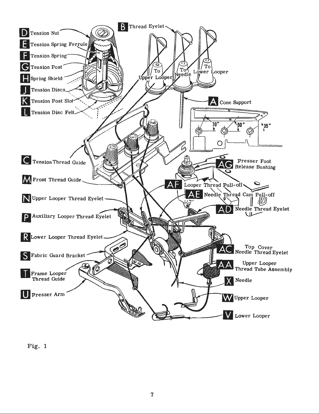
After
through
eyelet.
front
that
through
third
tension
front
back
Next
to
back
the
lower
the
through
discs
thread
of
the
freely
in
the
packaged
for
producing
three-quarters
pressure
lA)
and
until
21388
turn
AU.,
handwheel
needle,
needle
turn
handwheel
presser
thread
comes
hole
it
is
threaded
and
then
looper
upper
the
(J).,
hole
lower
through
guide
proper
through
operation
under
highest
on
swing
presser
needle
furnished
leave
in
holder
until
arm
(U)
of
thread
throu
thread
back
hole
(M).
needle
needle
our
of
Union
brand
size
eye
quality
of a century.
CHANGING
presser
foot
arm
is
at
its
with
until
needle
needle
until
it
holder
to
position;
THREAD
from
cones
eyelet
through
gh
the
lower
is
threaded
to
front.,
back
tension
to
post
is
in
Special
name,
needles
by
(U)
lowest
machine,
"is
holder
rests
is
again
re-lock
STAND
on
cone
(B).,
then
the
upper
holes
through
second
front.
slot
determined
order
to
machinee
~
in
NEEDLES
turning
out
point
presser
of
position.
of
loosen
at
high
position;
at
high
against
at
its
presser
(504
STITCH)
support
down
holes
from
the
throu
All
(K)
gh
threads
in
by
size
of
thread
produce a good
can
be
secured
.,
which
materials
travel.
needle
foot
Turn
Using
and
release
handwheel
clamp
withdraw
position
stop
low
(A.,
through
of
tension
back
tension
the
middle
tension
pin.
point
foot
Fig. 1 ),
the
to
front.
then
post
and,
Keeping
of
travel,
release
front
thread
thread
hole
continue
(G)
used.
stitch
formation.
only
is
backed
workmanship
bushing
in
hexagonal
nut
about
needle.
with
the
flat
needle
then
bushing
it
is
brought
hole
of
guide
It
should
guide
front
(C
to
between
and
on
Thread
by
use
by a re-
(AG,
opera-
socket
1/4
to
in
this
tighten
(AG).
thread
(C)
from
be
noted
),
first
back
and
the
through
for
the
up
6
Page 7
li]
Tension
II
Tension Spring Fe
II
Tension
[!]
Tension
IIJ
spring
Shield ... .-::::,~
Nut
Spring~
Post
r~
---~~~
l;)
Thread
Eyelet
O Tension
l3
Tension
II Tension
[i
Te
nsion
FIJ
Front
IIJupper
Iii
Auxiliary
(9Lower
Discs
Post
Disc
Thread
Thread
Looper
Looper
Looper
:~.::
··
Slot :
Felt
Guide
Guide
Thread
Thread
Thread
· ..
Eyelet
Eyelet
Eyelet
DFrame
Thread
DJ
Presser
Fig.
Looper
Guide
1
Arm
7
..
..,.,.
m
Top
Needle
Upper
Thread
Lower
Cover
Thread
Looper
Tube
Looper
Eyelet
Assembly
Page 8

m Tension
[!]
Tension Post
ll)
spring Shield
O Tension Di
(I
Tension
Nut
Post
scs
..
· ..
__
Slot ·.
(;)
Thread Eyelet
---...
i
I
I
I
I
I
\
I
_
I
I
I
n Te
[i
f,I)
(II
nsion
Dis
c Felt
Tension
Front
Uppe r Looper
Thread
Thr
ead Guide
·.
Guid
Thread
t,
Eyelet
Iii
Auxiliary
i9
Lower
(il
Fabric
D
Frame
Thread
m
Presser
Fig.
lA
Looper
Looper
Guard Bra
Looper
Guide
Thread
Arm
Thread
Eyelet
cket
Eyelet
8
..
lllli..
~
m
Top
Upper
Looper
Looper
Cover
Looper
Tube Aa
Needle Thread
Thread
Upper
Lower
Eyelet
sembly
Page 9
THREAD
STAND
(512
STITCH)
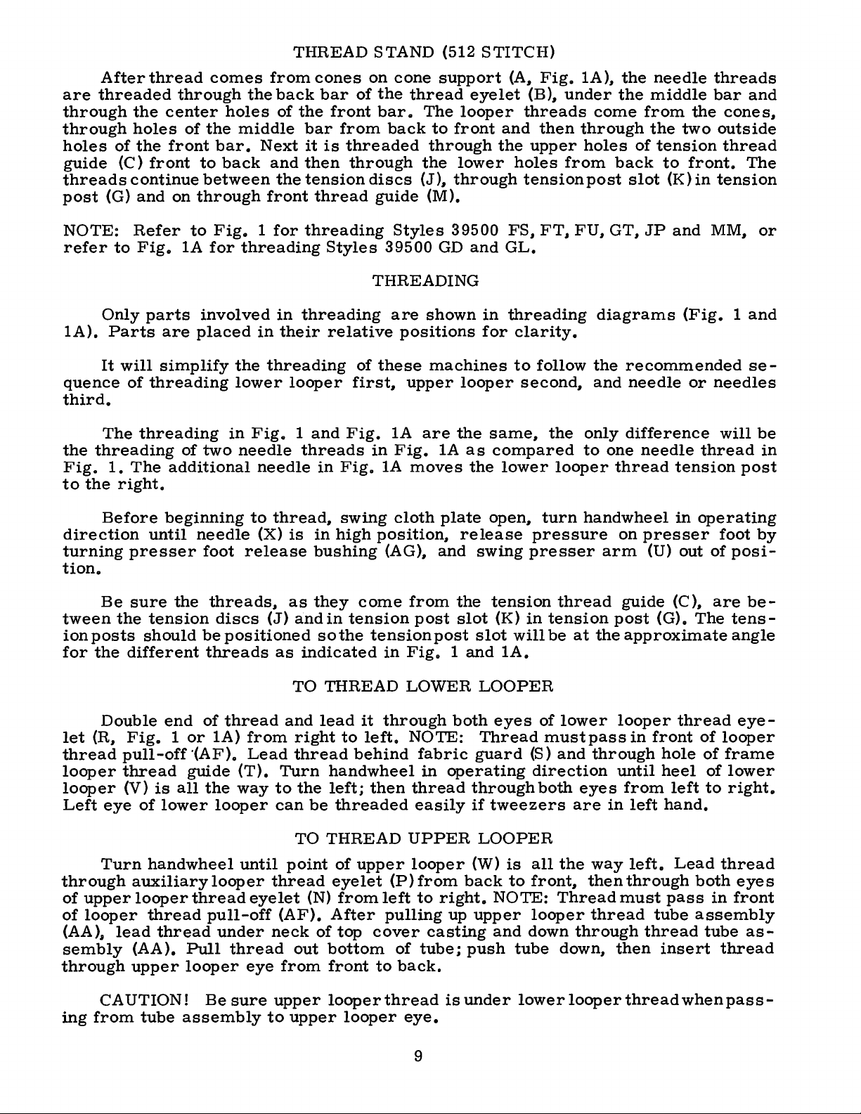
After
are
threaded
through
through
holes
guide
threads
post
third.
the
to
(G)
NOTE:
refer
Only
lA).
quence
Fig.
Parts
It
The
threading
1.
the
thread
the
holes
of
the
(C)
front
continue
and
Refer
to
Fig.
parts
will
of
threading
threading
The
right.
comes
through
center
of
the
front
on
are
simplify
additional
bar.
to
between
through
to
Fig. 1 for
lA
for
involved
placed
of
two
from
the
holes
middle
Next
back
and
front
threading
in
the
threading
lower
in
Fig. 1 and
needle
needle
cones
back
of
the
bar
it
then
the
tension
thread
threading
in
threading
their
looper
threads
bar
of
front
from
is
threaded
through
Styles
relative
of
first,
Fig.
in
Fig.
on
cone
the
bar.
back
discs
guide
Styles
39500
THREADING
are
these
lA
in
Fig.
lA
support
thread
The
to
front
through
the
lower
(J),
through
(M).
39500
GD
shown
positions
machines
upper
are
the
lA
moves
looper
looper
eyelet
and
the
and
in
for
same,
as
compared
the
lower
(A,
Fig.
(B),
under
threads
then
upper
holes
FS,
GL.
threading
clarity.
to
second,
from
tension
FT,
follow
the
looper
lA
),
the
come
through
holes
back
post
FU,
GT,
diagrams
the
and
only
to
one
thread
the
needle
middle
from
the
of
tension
to
slot
(K)
JP
recommended
needle
difference
needle
threads
bar
the
two
front.
in
and
MM,
(Fig. 1 and
or
needles
thread
tension
and
cones,
outside
thread
The
tension
or
se
will
be
in
post
-
Before
direction
turning
tion.
Be
tween
ion
for
let
thread
looper
looper
Left
through
of
of
(AA).
sembly
through
the
posts
the
Double
(R,
eye
Turn
upper
looper
lead
beginning
until
presser
sure
different
Fig. 1 or
pull-off
thread
(V)
auxiliary
(AA).
upper
the
tension
should
end
guide
is
all
of
lower
handwheel
looper
thread
thread
Pull
looper
needle
foot
threads,
discs
be
positioned
threads
of
thread
lA)
·(AF).
the
looper
looper
thread
pull-off
under
thread
to
thread,
(X)
release
(J)
from
Lead
(T).
way
until
thread
eyelet
neck
eye
is
as
and
as
indicated
TO
and
right
thread
Turn
to
the
can
be
TO
point
(N)
(AF).
out
from
swing
in
high
bushing
they
come
in
tension
so
the
tension
THREAD
lead
it
to
left.
behind
handwheel
left;
then
threaded
THREAD
of
upper
eyelet
from
After
of
top
cover
bottom
front
cloth
position,
(AG),
from
post
in
Fig. 1 and
LOWER
through
NOTE:
fabric
in
thread
easily
UPPER
looper
(P)from
left
to
pulling
casting
of
tube;
to
back.
plate
release
and
swing
the
slot
post
slot
LOOPER
both
Thread
guard
operating
through
if
LOOPER
(W)
back
right.
up
upper
push
open,
tension
(K)
eyes
tweezers
NOTE:
and
presser
in
will
lA.
is
to
down
tube
pressure
(S)
all
front,
looper
turn
tension
be
of
must
direction
both
handwheel
arm
thread
at
the
lower
pass
and
through
eyes
are
the
way
then
Thread
thread
through
down,
in
on
presser
(U)
guide
post
approximate
looper
in
until
from
in
left
left.
through
must
then
(C),
(G).
thread
front
hole
heel
left
hand.
Lead
pass
tube
thread
insert
operating
foot
out
of
are
The
of
looper
of
of
to
thread
both
in
assembly
tube
thread
by
posi-
betensangle
eye
frame
lower
right.
eyes
front
as
-
-
CAUTION!
ing
from
tube
Be
sure
assembly
upper
to
upper
looperthread
looper
eye.
9
is
under
lowerlooperthreadwhenpass-
Page 10

TO
THREAD
THE
NEEDLE
Turn
is
at
its
highest
both
eyes
through
front.
The
(D.
Fig. 1 or
formation.
PRESSER
Sufficient
should
decrease
nut
(A.
has a right
loosening
screw
presser
(C)
so
to
1/16
justing
of
hole
amount
be
Fig.
(B)
foot
that
inch
screw
handwheel
position.
needle
or
FOOT
maintained.
amount
2)
hand
decreases
has
its
(.
thread
holes
of
tension
lA).
Tension
PRESSURE
presser
of
and
turn
thread
been
resting
under
79
to
(B).
Set
in
operating
Insert
eyelet
in
top
foot
Should
pressure
adjusting
so
pressure.
properly
on
throat
surface
1.
59
mm)
cap
needle
(AD).
cover
THREAD
on
needle
on
threads
pressure
it
be
on
screw
tightening
set.
plate.
is
from
(D)
against
direction
under
needle
and
to
necessary
presser
When
tighten
approximately
the
until
thread
neck
thread
TENSION
looper
should
feed
work
foot.
(B).
Adjusting
increases
pressure
lock
position
top
locking
needle
or
threads
of
eyelet
threads
be
only
uniformly
to
increase
loosen
pressure.
nut
(A).
locking
1 / 32
surface
nut
(C).
or
needles
from
top
cover
(AC).
is
enough
or
lock
screw
adjusting
With
nut
inch
of
ad-
right
casting;
Thread
regulated
to
secure
(X.
Fig. 1 or
to
left.
and
by
proper
Fig.
through
then
needle
tension
2
lA)
down
from
nuts
stitch
Feed
approximately
feed
eccentric
39540
of
stitches
will
be
eccentrics
Generally
of
stitches
give
the
Following
5.,
6.
B-4.
shipped
proper
1.
8.,
eccentrics
obtainable
used
produced;
used
14
stitches
is
No.
39540
Minor
9.
numbers
when
with
speaking.
differential
stitch
10. 11. 12. 13.
on
above
the
the
number
other
FEED
in
Style
per
inch.
B-14
of
the
using
the
differential
that
combination
styles
main
or
gathering
feed
14.,
40.
chine.
ately.
a
stitches
ASSEMBLING
ECCENTRICS
39500
while' that
part
of
(right
eccentrics
15.,
Only
minor
FS
It
will
symbol
eccentric.
of
machines
hand)
(left
hand)
action.
16.,
two
Additional
To
order
number
desired.
machines
be
noted
of
the
differential
indicate
Unless
eccentrics.
covered
feed
eccentric
feed
are
available
18.,
20.,
eccentrics
eccentrics
an
eccentric.
suffixed
Example:
AND
ADJUSTING
have
that
approximately
otherwise
Refer
in
eccentric
22. 24.
are
been
the
"39540
selected
part
feed
to
this
catalog.
determines
is
under
26.,
28.,
supplied
may
use
to
indicate
SEWING
number
eccentric
specified.
exploded
selected
No.
30.,
with
be
ordered
No.
39540 B with
B-14".
to
produce
of
is
the
number
machine
views
the
number
so
39540
32.,
34. 36.
each
separ-
number
PARTS
main
No.
for
as
to
B-4.
ma-
of
Fig.
3
Before
remove
knife
follow
assembly.
this
assembling
cloth
suggested
10
plate.,
lower
fabric
sequence.
and
guard.,
knife
adjusting
chip
holder
sewing
guard.,
assembly.
parts.
upper
then
Page 11

SETTING
THE
NEEDLE
in
needle
At
this
into
stroke,
center
21225-1/8,
MM.
at
(1.
gauge
left
59
bar
of
On
end
mm)
No.
set
Styles
deflecting
differential
Fig.
driving
point,
(B).
With
looper
needle
on
Styles
39500
of
its
from
21225-1/16.
needle.
(front)
4
arm.
insert
lower
point
(Fig.
stroke,
center
Tighten
feed
5),
39500
GD
of
Do
dog.
lower
looper
1/8
using
and
set
left
not
nut
should
needle
1/2
for
inch
align
move
clamp
ly,
laps
looper
looper
looper
inch
FS,
FT,
GL,
looper
needle,
have
(C
With
inch
Styles
(11.
needle
tighten
If
looper
at
left
(3.17
looper
FU,
with
point
lower
).
Now
throat
center
is
at
(12.
91
needle
screw
needle
thread
pull-off
(A,
end
mm)
gauge
GT,
lower
1
using
assemble
in
high
70
39500
mm)
or
driving
(C).
clamp
thread
thread
Fig.
of
from
JP
looper
/16
inch
looper
looper
plate
the
front
position,
mm)
FS,
above
FT,
for
set
the
After
screw
cam
pull-off
pull-off
screw,
5)
its
No.
and
assembled
end
needle
throat
FU,
GT,
Styles
height
arm
39500
above
(B,
needle
and
remove
pull-off
(B),
back.
be
sure
in
position,
of
needle
point
plate
JP
and
GD
the
Fig.
has
been
(A,
separate
When
to
take
Fig.
elot.
should
(A,
MM;
and
throat
3)
by
loosening
set
proper-
throat
Fig.
4)
by
retightening
up
end
5
needle
When
be
set
Fig.
GL.
3)
15/32
To
plate,
plate.
over-
moving
play
Fig.
needle
guard
Tighten
SETTING
Assemble
is
springing
as
close
to
adjust
the
r e
6
nut
THE
as
possible
and
is
surface
(C,
Fig.
FRONT
front
needle
set
no
int
SETTING
Set
out
interfering
knife
holder,
ward
rear
rear
needle
needle
SETTING
Now
lower
should
7)
until
another.
5)
NEEDLE
needle
off
rear
to
needle
front
needle
e r
fer
THE
rear
REAR
needle
but
•
002-.
004
guard.
guard
THE
LOWER
finish
looper
be
the
set
into
needle
002-.
moves
securely.
GUARD
guard
(C,
needle
without
guard.
enc e between
guard
with
still
inch
Make
and
lower
the
springs
004
Fig.
guard,
touching.
After
NEEDLE
(A,
either
in
position
(.
051-.102
sure
lower
LOOPER
looper
to
the
needle
forward
inch
6).
When
set
front
Screw
this
needle
GUARD
Fig.
lower
looper
to
mm).
there
looper.
adjustment.
right,
scarf
from
(.
051-.102
lower
needle
(D)
setting
make
guards
6)
as
deflect
Screw
is
no
its
point
(A,
Fig.
rear
mm).
looper
guard
is
used
sure
and
high
or
as
movement
needle
(B)
interference
As
differential
possible,
of
or
needles
is
used
Fig.
feed
with-
lower
for-
to
set
between
7
dog.
11
Page 12

SETTING
THE
UPPER
LOOPER
Insert
holds
in
or
out
into
upper
(C
).
on
Locate
1/16
on
to
Styles
NOTE:
1/16
inch(.
When
upper
shank
and
MM
upper
or
upper
looper
turned
looper
looper
clamp
uprer
3 32
39500
On
the
looper
looper
inch
Style
79
to
upper
holder
holds
FS.
1.
approximately
(Fig.
8).
in
its
around
shaft.
the
in
(1.
59
FT.
39500
59
mm)
looper
should
vertical
NOTE:
should
vertical
sure
and
looper
upper
lower
clearance
(A.
holder.
its
if
it
upper
its
holder
to
2.
FU.
GD.
JP
the
beyond
be
on
casting.
shaft
looper
looper
Fig.
shank.
is
38
GL.
shank
is
at
be
set
on
•
On
Styles
set
when
all
styles.
(Fig.
8)
in
and
Insert
not
already
looper
so
mm)
GT
holder.
the
to
Styles
to
the
By
and
point
eye
9).
its
holder.
permits
upper
holder
that
the
beyond
and
MM.
should
right
end
position
39500
39500
position
upper
there
adjusting
by
turning
to
with
Screw
it
to
be
pushed
looper
in
place.
in
the
shank
holder
extend
of
its
extends
(Fig.
1/32
stroke.
upper
FS.
FT.
FU.
GD.
GL
and
upper
looper
looper
is
at
is a clearance
looper
the
looper
cross
•
002
lower
to
•
004
(B).
holder
Screw
shaft.
8)
to
looper
GT
JP
right
holder
looper
inch
the
upper
shank
end
between
in
around
(.
slightly
of
its
or
its
to
the
051
Fig.
looper
stroke.
heel
out
shank.
left
to
•
8
back
of
of
102
holder
of
Be
looper
upper
set
of
the
mm)
travel;
(Fig.
Fig.
10).
Styles
NOTE:
inch
(3.
settings
Fig.
check
1 O).
-
39500
For
97
are
9
dimensions
If
resetting
Figure
FS.
Style
and
12.
1/8
the
head
10
represents
FT.
FU.
39500
30
mm).
inch
As
heel
with
Next.
of
is
necessary.
GT
JP.
(3.17
and
17
ample
is
increased
holder
left
end
inch
upper
upper
are
made.
upper
to
maintain
the
of
the
1/64
turn
upper
upper
looper
looper
upper
to
1/32
handwheel
do
the
dimensional
and
MM.
the
settings
For
Styles
mm)
/32
dimension
to
inch
by
39500
the
(13.49
1/2
turning
counterclockwise
of
machine;
(3.
57
mm)
is
looper
looper
looper
:q.older
shaft.
it
may
around
the
condition
moves
looper
inch
point
it
are
with
by
5/32
GD
left
of
mm).
inch
dimension
increased
to
the
After
be
these
necessaryto
its
shank
should
(.40
until
looper
respectto
moving
setting
and
and
GL.
right
For
(12.
70
upper
looking
by
pulling
left.
changes
slightly
shown
toward
pass
to.
79
the
for
31/64
the
needle
ex-
mm)
looper
from
9 /
64
out
of
turn
in Fig.
the
behind
mm)
is
at
needle
upper
9.
top
of
its
the
lower
clearance.
the
left
and
throat
looper
holder
Fig.
end
10
stroke.
looper
of
its
plate
(A.
Fig.
11
When
quickly
when
upper
upper
the
as
looper
correct
follows:
looper
and
needle
As
eye
12
setting
upper
centers
should
is
obtained.
looper
on
align
the
exactly
is
moving
needle.
it
(Fig.
can
the
be
checked
to
the
eyes of
11 ).
right.
the
Page 13

SETTING
THE
UPPER
LOOPER
(Continued)
(B)
and
This
.a
straight
should
tating
lowers
The
first
feed
tilting
so
that
throat
higher
set
can
be
now
feed
the
feed
appear
teeth
plate.
if
desired.
both
checked
edge.
be
leveled
tilting
back
dogs
above
adjusting
rise
The
Fig.
feeds
by
Now
end
assemble
with
adjusting
of
both
should
the
pin
about
differential
12
so
the
sighting
throat
pin
feed
be
set
throat
in
place.
3/64
top
across
throat
(C
).
bars
level
plate.
inch
feed
surfaces
plate.
plate
This
at
at
Screw
Now
(1.19mm)
may
the
teeth
Feed
surface
pin
raises
the
same
the
time
(E)
set
feed
be
set
ference
needle
needle
per,
slightly
distance
from
maintain
11.
SETTING
dog
machine.
of
the
by
time.
teeth
locks
dogs
above
slightly
teeth
with
dogs
ro-
or
Check
pull
left
Now
(A,
setting
between
on
needle
rubs
the
looper
and
rotate
counterclockwise,
end
of
dimensions
THE
assemble
Fig.
all
12)
Assemble
lie
to
avoid
upper
downstroke.
back
machine.
FEED
in
of
out
of
looper a short
of
Figs.
DOGS
differential
if
not
main
the
same
inter-
looper
upper
its
holder
looking
Reset
9,
already
feed
plane.
and
If
loo-
to
10,
feed
on
dog
NOTE:
level
of
its
SETTING
(A,
throat
lower
justment
nut
cloth
not
setting
Upper
approximatelyl/64
surface
On
with
the
travel.
THE
Replace
Fig.
(C)
tightened
Replace
plate
knife.
Lower
against
plate
nut
knife
of
13)
is
the
Style
top
lower
should
surface.
Lower
necessary
knife
latch
against
upper
(E )
to
chain
upper
39500
of
throat
LOWER
knife
be
Adjustments
knife
may
be
support
spring,
lower
knife
hold
guard
inch
knife.
JP,
plate
KNIFE
holder
set
with
is
when
secured
bracket.
it
should
SETTING
assembly.
clamp
(G)
(.40
set
assembly.
spring
width
knife
(F )
should
mm)
the
chaining
when
cutting
are
pressed
of
trim
in
any
Because
always
holder.
in
it s
behind
feed
Lower
edge
made
is
position
screw
be
THE
Clamp
most
be
positioned
the
feed
is
at
the
flush
with
against
changed.
locked
UPPER
upp
clockwi
cutting
dog
top
knife
with
hexagonal
upper
by
tightening
(B)
also
with
KNIFE
er
knife
se pos
so
edge
serves
nut
that
head
knife,
(C)
(D, F
ition
the
and
screw
screw
as
even
ig.
again
guarding
in
contact
Fi.g ·
so
(B)
latch
13)
st
13
which
no
lateral
and
pin
when
in
position,
upper kni
section
with
holds
locking
for
screw
the
ad-
the
is
fe.
is
top
13
Page 14

SETTING
At
the
cutting
tend
below
edge
not
cutting
THE
bottom
less
UPPER
of
upper
than
edge
of
1 /
of
KNIFE
its
knife
64
inch
lower
(Continued)
stroke,
should
(.
knife.
4 0
front
ex
mm)
-
After
proper
be
width
tightened
holding
simplify
replaced.
SETTING
Length
the
used.
14)
dog;
(B)
combination
Outer
actuates
while
actuates
In
be
sure
(C)
and
washer
To
change
frame
from
(M).
stud
upper
of
trim,
to
block
(J)
resetting
THE
STITCH
of
stitch
(left)
differential
the
inner
the
assembling
hubs
are
(0)
feed
Remove
(J).
Link
knife
lock
in
when
of
eccentric
main
feed
facing
and
eccentric,
nut
(K)
has
been
screw
the
upper
place.
upper
LENGTH
is
determined
feed
(front)
(right)
(rear)
each
tighten
(C)
and
set
for
(H)
must
knife
This
will
knife
eccentrics
(A,
Fig.
feed
eccentric
feed
dog.
eccentrics,
other.
Be
securely.
remove
and
washer
eccentric
is
by
(A)
careful
thrust
(D)
from
will
not
finger
now
to
end
slip
Fig.
damage
(L)
from
of
shaft
off.
14
shaft
its
(G).
or
key.
seat
on
Remove
Use
the
nut
nut
main
(H)
by
an
stops
The
position
upper
determines
Fig.
of
15
the
and a lower
the
feed
differential
stop.
The
action.
Using
supplied
(B)
as
be
necessaryto
slightly
allow
the
• 003
thrust
connecting
SETTING
Differential
the
use
Style
3 95 00
screws
and
MM.
control
lever
amount
14
hooked
with
shown
during
inch
finger
rod
THE
of
one
JP
on
Styles
of
lever
eccentric
machine,
and
withdraw
move
reach
handwheel
extraction.
(.
076
mm)
and
the
differential
in
a 3
60°
turn.
DIFFERENTIAL
feed
action
micrometer
and
two
micrometer
(A,
39500
Fig.
FS,
15
and
movement
extractor
behind
eccentric.
back
When
reassembling
clearance
RA
is
obtainable
adjusting
FT,
FU,
15A)
between
eccentric
and
between
feed
TIO
screw
adjusting
GD,
is
governed
these
It
forth
drive
GL,
(E
may
thru
on
GT
two
),
.
Page 15

post
the
upper
the
lower
On
Style
ment.
On
Style
assembly)
stop
stop
39500
SETTING
39500
JP,
in a clockwise
(B)
down, a counterclockwise
screw
(C)
JP, the
THE
rotating
so
as
two
stops
DIFFERENTIAL
the
one
adjusting
direction
to
obtain
may
increases
the
be
reversed
RA
thumbscrew
the
turn
acts
required
to
TIO
(Continued)
(located
differential
in a reverse
intermittent
meet a specific
near
the
action
manner.
by
Now
differential
sewing
requir
tension
moving
set
feed.
e -
NOTE:
hold
in
ential
control
plain
thus
is
actuated.
After
this
position
feed
dog
adjusting
feed
control
increases
lower
does
Fig.
rod,
adjusting
the
Turning
stop
and
turn
not
strike
15A
it
amount
this
screw
handwheel
is
the
rod.
of
screw
has
the
been
throat
set,
in
operating
plate.
On
and
MM
controlled
control
stop,
moved
15A).
feed,
it
is
the
bed
Turning
amount
clockwise
The
feed
smaller
Turning
knurled
this
differential,
counterclockwise
push
Styles
lever
but
by
To
set
turn
the
in
of
is
set
when
differential
direction
39500
the
differential
by
the
between
on
these
an
adjusting
the
amount
the
plain
larger
knurled
back
this
rod
differential
increases
amount
by
head
screw
clockwise
the
differential
acts
FS,
movement
machines
feed
of
the
tension
clockwise
and
the
of
intermittent
turning
screw
the
reverse.
control
to
be
sure
FT,
FU,
feed
an
action
of
the
upper
both
thumbscrew
of
differential
control
head
adjusting
screw
post
decreases
turning
amount
the
located
of
differential
just
lowers
feed
control
lever
the
GD,
down,
differ
GL,
is
also
GT
differential
and a lower
stops
rod
or
are
(Fig.
plain
rod,
located
on
assembly.
the
it
counter-
differential.
differential
feed
the
above
stop
the
and
lever
-
,
SETTING
Assemble
With
into
sewing
align
throat
The
foot
must
hole
in
bottom
plate.
aligned
lifter
loosen
screw
Retighten
THE
needle
needle
plate.
front
throat
of
If
necessary,
with
lever
collar
(G)
collar
in
position
holes
be
aligned
plate.
the
presser
throa,t
shaft
and
PRESSER
the
presser
high
position,
and
(front
edge
of
with
It
presser
plate
(H,
Fig.
screws
then
shift
screws
FOOT
set
needle
is
also
foot
slots
16).
(B,
the
and
foot
swing
the
and
front
important
be
by
Tomove
Fi
g.
foot
clamp
to
presser
presser
back)
hole
edge
flat
on
foot
shifting
16)
lifter
presser
and
in
presser
of
that
the
can
the
the
and
lever
screw.
arm.
arm
foot
flat
needle
throat
be
re-
foot
shaft,
clamp
to
on
the
shaft
to
15
the
left
Fig.
or
16
right
as
required.
Page 16

The
sure
locked.
the
foot
lifter
presser
SETTING
lever
arm
does
arm
not
THE
(A.
bind
PRESSER
Fig.
or
16)
rise
FOOT
and
when
(Continued)
the
collar
presser
(B)
foot
secure
release
the
shaft.
bushing
is
Be
un-
Adjust
than
upper
1 / 8
inch
begins
(F).
Re-assemble
guard.
Styles
down
presser
a
is
below
shim
Loosen
position
against
remove
NOTE:
face
plate
more
shown
the
(B)
of
lifter
looper
(1.
to
rise.
turn
39500
(A.
foot
flat
pucker
in
Fig.
throat
under
screws
and
the
presser
the
shim.
Always
throat
SETTING
lever
will
5 9
to
3.
1 7
This
the
handwheel
SETTING
FT.
Fig.
and
when
free
17.
Set
plate
the
front
(D)
which
move
be
plate
the
foot.
sure
when
stop
screw
permit;
mm)
adjustment
chip
until
FU.
17
).
set
and
plate
THE
free
guard.
upper
THE
GD.
The
correctly
seam.
the
machine
insert
portion
hold
down
Tighten
the
feed
making
PRESSURE
39500
(C)
then
PRESSER
GL.
purpose
An
FT.
lock
motion
should
fabric
knife
GT
it
approximate
with
a.
005
of
presser
the
hold
until
the
dogs
this
FU.
so
that
the
of
be
made
guard
assembly
FOOT
and
MM
of
this
will
help
the
inch
down
it
rests
two
screws
are
below
setting.
PLATE
GD.
GL.
presser
nut
(D ).
foot
lifter
with
and
reaches
HOLD
are
equipped
plate
produce
setting
feed
dogs
(.
127
mm)
foot
(C).
plate
firmly
and
sur-
ASSEMBLY
GT
and
foot
There
lever
screw
cloth
DOWN
is
to
in
MM)
can
be
raised
should
before
(E)
plate.
its
highest
PLATE
with a presser
hold
(FOR
the
and
To
down
Fig.
STYLES
be
from
presser
locked
assemble
position.
the
rear
17
no
with
foot
higher
1 /
16
foot
nut
chip
hold
of
the
to
4.
with
to
easily.
With
throat
flat
pressure
inner
allow
the
on
screw.,
assembly
Lock
feed
plate
the
throat
plate
Fig.
inner
dogs
from
(A)
18
after
to
screw
down.,
the
plate.
and
removing
snap
with
front
If
not.,
adjust
into
look
of
outer
place
outer
horizontally
the
loosen
flat
and
screw
machine
the
to
the
1.
2.
3.
screw
still
(C).
to
two
throat
Swing
in
tion
hinges
loosen
adjust
smooth
Loosen
turn
clockwise
side
wrench
tension
cated
the
forced
Adjust
the
(C ).
allow
between
assure
screws
the
and
and
freely
the
of
machine)
in
pressure
down
mounting
Spring
the
that
plate.
pressure
out
of
its
check
on
lock
operation.
set
provided.
on
tension
the
(D.,
nut
shoulder
screw
shaft
the
collar
(viewed
the
shaft
plate
slightly.
bracket
should
mechanism
pressure
the
pressure
Fig.
plate
operating
to
assure
its
(A.
Fig.
screw
(C.
from
using
so
there
tension
bracket
(A.,
spring.
be
19)
which
assembly
pivot.
Fig.
(D)
the
spring
Fig.
located
(B.,
tight
to
swing
plate
plate
posi-
that
If
not.
18)
and
(B)
for
18)
and
counter-
the
left
spanner
is
some
lo-
(E)
and
19)
Fig.
enough
and
lies
hold
19)
out
the
the
it
is
in
16
Page 17

5.
Raise
that.
Retighten
6.
Adjust
to
SETTING
or
from
the
feed
lower
screws
screw
dog
the
THE
39500
the
side.
(E
(F.
Fig.
teeth.
PRESSURE
FT.
FU.
mounting
the
pressure
).
19)
so
Lock
with
GD.
GL.
bracket
that
screw
PLATE
GT
(B.
plate
the
front
(G).
ASSEMBLY
and
MM)
Fig.
is
19)
parallel
edge
of
,.,..
. , .
. ~\)
..
I
.005-.010
( .127
to
(FOR
(Continued)
by
loosening
and
fl.at
the
pressure
,,
.254mm)
STYLES
screws
on
the
throat
plate
is
(E)
so
plate.
square
7.
8.
9.
10.
Center
ing
laterally
When
pressure
mately
operating
With
pressure
pass.
moving
(E).
The
revolution
presser
of
the
away
pressure
collar
retightening
• 005
feed
If
the
Recheck
actuating
presser
without
(F.
as
required.
plate
lever
dogs
plate
not.
mounting
of
foot
plate
Fig.
to • 010
up,
adjustment
Step
collar
the
is
foot
moving
18)
operating
are
down.
and
shaft
check
and
the
bracket
4.
machine.
1/
32
inch
if
the
over
and
inch
presser
(F,
it
is
the
the
lever
then
(.127
bracket
from
can
be
(B)
Fig.
the
(.
79
mm).
important
presser
Fig.
feed
dogs
operating
screw
tighten
to • 254
(E.
Fig.
the
left
foot
is
made
straight
18)
should
minimum
The
that
foot
away
19
by
loosening
lever
make
operating
mm)
side
wide
by
toward
distance
lifter
clearance
18).
to
enough
loosening
now
the
shirring
first.
(G).
sure
lever
see
the
be
between
rod
should
the
and
that
screw
(See
if
the
to
allow
screws
operator.
set
so
mechanism
screws
then
the
clearance
that.
the
be
adjust
feed
leaving
Fig.
the
(E,
Retighten
throughout
lifter
set
to
in
the
shaft
dogs
approxi-
19)
between
largest
Fig.
rod
clear
can
be
actuat-
(H)
and
the
between
the
seam
19)
and
screws
one
and
the
the
tip
swung
11.
Loosen
spring.
quired
set
screw
Turn
to
shaft
obtain a uniform
(C.
Fig.
collar
18)
(D)
with
shirr.
for
final
spanner
Retighten
17
adjustment
wrench
set
screw
of
until
(C).
pressure
desired
plate
tension
tension
is
ac-
Page 18

NEEDLE
THREAD
CONTROL
While
needle
should
slightly
stroke,
pull-off
With
lA)
back
reaches
inch
guide
lower
travel.
portion
per
tension
eyelet
(3.
While
thread
thread
be
just
if
position
(AE)
material
far
its
1 7
(T)
should
looper
of
while
(R)
sewing
is
tight
excessive
needle
just
enough
most
mm)
distance
(V)
sewing
lower
comes
down,
looper
lower
keeping
on
material,
drawn
enough
thread
contacts
LOWER
under
so
rearward
be
set
heel
on
off
looper
eyelet
material,
thread
upper
UPPER
on
needle
to
thread
needle
presser
thread
position.
behind
with
looper.
thread
the
check
feed
is
pulled
eyelet
thread.
LOOPER
foot,
is a little
needle
its
eyelet
at
the
check
should
same
LOOPER
needle
down
chain
on
(AD,
set
Looper
thread
apprxoimately
time
drawing
be
drawn
To
increase
is
on
amount
thread
stroke.
off
stitch
the
up
Fig. 1 or
THREAD
lower
slack
thread
cam
lower
upper
of
THREAD
looper
off
through
amount
looper,
pull-off
control
At
top
tongue.
stroke.
lA)
so
CONTROL
looper
when
pull-off
CONTROL
pull-off
of
looper
the
action.
thread
looper
1/8
is
of
move
as
of
needle
Stitch
With
that
(AF)
(AE).
inch
at
extreme
thread
tension
thread
follows:
stroke,
tends
needle
needle
eyelet
thread
is
Frame
(3.17
before
drawn
lower
Usually
to
pull
at
bottom
thread
(R,
pull-off
set
about
looper
mm)
left
end
as
follows:
lower
through
looper
all
thread
down
of
cam
Fig. 1 or
(AF)
1/8
thread
right
of
of
its
A
loo-
the
thread
Before
ance
in
draw
is
pull-off
Fig.
better
all
that
to
edge.
all
these
During
upper
drawn,
To
1
If
end
it
form
three
tensions
upper
reaches
move
or
lA)
to
have
it
becomes
play
is
higher
near
proceeding
or
four
will
needle
looper
the
in
top
down
thread
looper
it
most
purl
should
slightly
necessary
needle
over
edge.
to
tensions
not
markedly
stroke,
through
thread
rearward
more
be
raised
more
drive
throat
If
upper
adjust
plate
upper
to
give a normal
affect
forward
the
will
position.
POSITIONING
under
pull-off
to
shaft
the
keeping
move
before
than
looper
THREAD
looper
the
stroke
tension.
have
almost
THE
edge,
the
same
on
upper
looper
recommended
thread
tightening.
is
too
TENSIONS
thread
appearing
purl.
of
When
all
PURL
both
thread
low,
eyelet
looper
normal
slack
looper
amount
than
pull-off
If
upper
in
(Fig.
the
purl
(N,
stitch.
thread
amount
taken
thread
of
pull-off.
on
lower
(AF),
10),
will
Fig. 1 or
Moderate
pull-off
of
up
as
eyelets
thread.
be
sure
looper
the
form
looper
looper
Usually
to
is
located
purl
nearer
lA)
change
(AF)
thread
thread
(N
and
take
will
bottom
bal-
will
R,
it
is
up
so
tend
The
being
ble
without
should
is
pulled
needle
sewn.
be
increased
too
thread
In
general,
causing
far
over
tension
lower
needle
as
long
the
thread
as
top.
required
looper
to
the
elasticity
is a function
thread
be
tension
pulled
of
18
down.
the
chain
should
of
needle
be
Upper
increases,or
thread
set
as
looper
and
high
thread
until
material
as
possi-
tension
the
purl
Page 19

TO
REMOVE
Fig.
20
CRANKSHAFT
Crankshaft
1.
Drain
of
2.
Remove
3.
Remove
eccentric
4.
Remove
5.
Remove
will
6.
Remove
through
can
oil
base.,
be
re-assembled
bottom
be
withdrawn
by
removing
top
and
feed
eccentric
extractor.,
key
(D).,
three
screw
counterweights
(F)
bottom
which
of
bed
easier
plug
covers
nut
slip
off
in
the
holds
casting.
screw
of
(A.,
Fig.
the
(E).
proper
crankshaft
if
these
located
machine.
20)
eccentrics
Identify
places.
19
steps
on
and
split
are
back
washer
(C).
these
bearing.
followed:
of
machine
(B)., and.,
counterweights
This
near
with
screw
bottom
the
so
that
is
aid
of
reached
edge
the
they
Page 20

7.
8.
Remove
crankshaft
When
make
ginal
stamped
and
on
Also.,
bled
they
Loosen
which
arm
through
arm
driving
rod
bearing
ing
shaft.
when
scribed
re-assembling
sure
position.
both
the
same
screws
in
the
were
holds
(B).
to
lever
(D)
drop,
cap
point
Observe
re-assembling
in 7 above.
caps
at
points
they
on
both
trade
side
should
same
removed.
clamp
upper
Access
top
cover.
the
left
allowing
(E).
(K,
TO
of
are
Trade
halves
marks
of
holes
nut
until
(C)
This
Fig.
same
REMOVE
bearings
G.,
H,
bearing
in
marks
of
should
the
be
re-assem-
from
(A,
knife
to
clamp
Draw
upper
and
connecting
removal
is
20)
precautions
cap
and
caps
their
bearings.
on
the
which
Fig.
driving
nut
driving
at
bear-
crank
as
ori-
are
caps
knife
de-
CRANKSHAFT ( Continued)
on
J.
be
21)
is
of
Fig.
21
9.
10.
11.
12.
13.
14.
15.
16.
1
7.
Remove
screw
Loosen
Remove
Loosen
Remove
collars
Crankshaft
If
bor
against
Carefully
assembly
parts
Before
gaskets.
wick
that
cover.
prevent
is
two
two
(V)
necessary
press.
ground
and
re-assembling,
which
it
contacts
Coat
oil
screw
reached
screws
screw
screws
three
and
may
to
In
replacing
thrust
observing
of
crankshaft.
constant
Before
lubricates
oil
leakage.
(L,
Fig.
through
(M)
in
(N);
take
screws
(W)
may
now
replace
testing
re-assembling
shaft.
drain
off
(R);
remove
(T);
be
be
removed.
ball
bearing
washer
reverse
Checking
thoroughly
left
The
plug
No. 1 Crane
20)
which
bottom
fan
collar;
pulley
take
removed
bearing
(Y).
of
for binds
crankshaft
wick
with a sealing
holds
of
cap
pulley
off
it
must
the
exploded
during
bottom
stands
Lead
inner
bed
casting.
remove
(P).
(S).
bearing
at
this
(X),
it
be
foregoing
clean
cover
bearing
vertically
Seal
right
both
halves
retaining
time.
should
pressed
view
re-assembly
and
compound
is
be
operations
drawings
dry
top
make
is
recommended.
sure
inserted
on
crankshaft
of
plate
pressed
on
carefully
should
for
will
and
that
in
its
spring
before
bearing.
cooling
(U);
off
location
also
bottom
spring
hole
re-assembling
fan.
also,
shaft
until
simplify
of
prove
covers
pressed
in
casting
against
spacer
on
an
it
seats
various
helpful.
bottom
This
ar-
re-
and
oil
and
to
20
Page 21

ILLUSTRATIONS
This
catalog
of
various
actual
listing
required
sections
position
of
the
in
the
in
parts
particular
has
the
been
of
the
machine.
with
ORDERING
arranged
mechanism
On
their
view
part
being
REPAIR
to
simplify
are
the
page
number.
shown.
ordering
shown
so
opposite
description.,.
PARTS
that
the
the
repair
parts.
parts
illustration
and
may
the
Exploded
be
seen
will
number
be
in
found
of
pieces
views
their
a
Numbers
position
in
ordering
Component
indicated
assembly.
40
41
42
43
44
45
not
mended.
this
part
39544
39544
It
will
listed.
At
the
book.
number
of
that
parts.
by
Example:
29126
22729
97
22729
be
The
so
back
This
in
the
part
Always
parts
indenting
DF
D
S
U
E
noted
complete
is
in
reason
of
the
will
known.
first
column
in
the
use
of
sub-assemblies
their
Lower
RodAssembly---------------------------------------
Screw.
Screw.
Ball
Lower
Screw.
the
above
is
that
sub-assembly
book
facilitate
are
reference
illustration.
the
part
descriptions
Looper
for
for
Joint
Looper
for
example
replacement
should
will
be
found a numerical
locating
IDENTIFYING
Reference
number
Bar
No.
No.
Guide
No.
that
the
numbers
listed
which
under
Driving
39544 N ---------------------------
39544 S ---------------------------
Fork-----------------------------
Bar
39544 N ---------------------------
the
of
be
illustration
can
the
Lever
Driving
eccentric.,.
these
ordered.
PARTS
only.
numbers
in
be
description
Lever
parts
index
and
and
merely
should
the
second
furnished
and
Connecting
------------------
ball
stud.
individually
of
all
description
column.
for
of
and
the
parts
indicate
never
repairs
the
bearing
is
not
when
be
main
recom-
shown
only
the
used
are
sub-
1
2
2
1
1
2
are
in
the
Where
some
identification
appear.
Union
its
most
mum
parts
trademark
forwarded
wise
of
the
Part
Success
subsidiaries
Genuine
Prices
numbers
Special
approved
efficiency
are
stamped
directed.
the
construction
smaller
letter
in
the
Needles
scientific
and
needles
is
your
are
net
f.
o.
b.
A
permits.,.
parts.,.
is
stamped
represent
USE
operation
and
and
authorized
durability
are
with a reproduction
guarantee
cash
shipping
charge
and
on
in
the
GENUINE
of
Repair
principles.
are
packaged
of
and
are
point.
is
made
Parts
subject
each
those
to
same
NEEDLES
these
distributors.
assured.
with
the
Parcel
to
where
distinguish
part.
machines
as
furnished
and
labels
of
the
highest
TERMS
to
Post
cover
postage
part
is
the
the
regardless
AND
They
are
made
marked~.
familiar
quality
change
shipments
stamped
construction
part
from
of
REPAIR
can
be
secured
by
the
Union
are
designed
with
Union
in
without
and
utmost
Special
materials
notice.
are
insurance.
with
its
does
similar
the
catalog
PAR'IB
Special
insured
part
number.
not
permit.
ones.
in
which
only
with
Corporation
according
precision.
Genuine
trademark.
and
workmanship.
All
shipments
unless
On
an
they
genuine
to
the
Maxi-
repair
Each
are
other-
21
Page 22

22
Page 23

MAIN
FRAME,
MJSCEJ LANEOUS
CO
E RS AND
PLAT
ES
39501
o
39501
39501
39501
226
9578
22
22569
39501
29477
22743
39568
39568
22
39557
39563
39563
22569
395
39557
39557
39557
39557
39556
39582
39582
22562
39582
39582
39582
39582
39582
22541
2256
22569
22569
22565
39594
22894
39593
39582
22653
39582
39582
39595
22586
39
22569 C
22569
39593
22
39578
39594
22569
Part
No.
E C
E
57
138
565 F
571 E
A
W
57
C
E
A
AD
AK
A
W
51-103
A
V
AF
AE
667
D-8
5 S
K
D
R
AD
H
660-243
F
D-4
Y
X
R
532 A
90
;-
D
569 D
W
G
B
Ref.
No.
1
lA
2
3
4 3
5
6 22569 C
7 3 9535 H
8 ,
9 •
10
11
12
13
14
15
16
16A
17
18
19
20
21
22
23
24
25
26
27
28
29
30
31
32
33
34
35
36
37
38
39
40
41
42
43
44
45
46
47
48
49
50
51
52 39593 C
53
54
55
56 39 594 H
57
58
DC
D
D-12
K
K
GW
J
G
F
B
F
B
Blk.
Description
Cloth
Plate,
except
Cloth
Plate,
39500
Cloth
Plaf;,
39500
Cloth
Plate,
Screw,
Screw,
Cloth
Plate
Screw,
Screw,
Feed
Bar
Screw,
Cloth
Plate
Upper
Screw,
Thread
Thread
M
agnetic
Presser
Top
Cover
JP,
MM---------------------------------------------------------
Top
Cover
Screw,
Presser
Lock
Nut,
Presser
Presser
Presser
Presser
Top
Cover,
Top
Cover,
Screw,
Oil
Hinge
Hinge
Spring-------------------------------------------------------
Oil Filler
Top
Cover
Screw,
Dowel Pin--------------------------------------------------------
Spot Screw,
Screw,
Screw,
Set
Screw,
looper dri
Oil
Collector Plate
S
crew,
Oi l S
ig
ht
Oil
Gauge
B
ottom Cover
Scr
ew,
B
ottom Cov
B
ottom
R
ubber Isolator---------------------------------------------------
S
crew, for
Cloth Plate Latch
Screw, for
Screw,
Screw, for
Oil
Gauge Float
Oil
Gau
Screw, for chip g
Ch
ip
Guard-------------------------------------------------------
Oil
Strainer------------------------------------------------------Oil Filter
Screw,
for
semi
or
fully
39500
JP-------------------------------------------------------JP-------------------------------------------------------for
for
for
for
for
Looper
for
Spring--------------------------------------------------Spring
Spring
Spring Plunger Cap
Guard-----------------------------------------------------
for
for
for
for
for
Cover-----------------------------------------------------
for
ge Indi
for
JP------------------------------------
for
semi
or
for
non
submerged
for
non
cloth
cloth
Fabric
feed
feed
Gui
de---------------------------------------------------
cloth
Stud---------------------------------------------------
Thread
for
Tube
Tube--------------------------------------------------
Oil
Drain
Spring
Needle
Needle
top
for
presser
Foot
Release
for
for
for
Pin-----------------------------------------------------
Bracket------------------------------------------------
Cover
Gasket-------------------------------------------------
top
for
oil sig
oil
collector
for
ve
lever
lower
Gauge---------------------------------------------------
Seal
and Base
bottom
er Gasket ----------------------------------------------
bottom
cloth
bottom
bottom
cator------------------------------------------------
Screen--------------------------------------------------
oil filter
submerged
pfate --plate
fabric
Guard------------------------------------------
adjusting
bar
guide
plate
stud
thread
Plunger---------------------------7------------
cover
Plunger
Plunger
Styles
Styles
oil
cover-----------------------------------------------
upper
Ring -----------------------------------------------
Tube
tube
Tension
Plug
Thread
Thread
needle
spring plunger
Bushing-------------39500
39500
guard-------------------------------------------
----
upper
____
looper
ht gauge------------------------------------------
looper thread
shaft-------------------------------------------
------------------------------------------------
looper
Plate Ext
cover
cover -------------------------------------------
Spr
ing
plat e la
uard----------------------------------------------
tch
cover
cover
:_
______________________________________________
screen-----------------------------------------
submerged
fully
subm
e r g
installation,
installation,
- - ------
pin
- ---- ---- - ---- ----- -- --
----------------------------------------Assembly--------------------------------
tension
Spring------------------------------------
Screw
Eyelet,
Eyelet,
thread
Adjust
Locking Nut
Nut
FS,
GD,
---
plate---------------------------------------
bar
driving lever shaft-----------------------
extension
------------------------------------------spr ing
-------------------------------------------
-------------------------------------------13
- - - - - - - - -
guard----------------------------------
---------------------------------------
spring----------------------------
------------------------------------for
for
eyelet----------------------------
ing S
crew-----------------------------
------------------------------------
FT,
GL ---------------------------------
---
- -
-- ------ --------------
drive
lever
tube assem
ens
----------------------------------
----------------------------------
installation,
ed
installation,
for
for Style
-----------
Styles
Styles
adjusting
--------------------------------
F U,
ion------------------------------
39500
39500
-
GT, JP,
shaft
bly and
screw-----------------
-----------------------
-----------------------
for
for
all
Styles
39500
- -
----
FS,
FT,
GD,
GL
MM
------------------
for
all Styl
-
------------
Style
except
JP
- -- - - -
upper
--------
----
- ---- -
FU,
GT,
-------------
---
-- -------
es
- ---1
-- ----
~
---
Amt.
Req.
1
1
1
1
2
1
1
- 1
1
1
1
1
1
1
1
1
1
1
1
2
1
1
1
1
1
1
1
1
1
1
1
1
1
1
1
8
2
1
1
1
2
1
2
1
1
1
2
1
1
1
1
1
2
1
1
1
2
1
1
1
2
23
Page 24

•
24
Page 25

RANKSHAFT
C
MECHANISM
AND BUSHINGS
Ref.
No.
1
2
3
4
5
6
7
8
9
10
11
12
13
14
,:,15
,:,
16
'~
17
*18
19
20
21
22
23
24
25
26
27
28
29
30
31
32
33
34
35
36
37
38
39
40
41
42
43
44
45
46
47
48
49
50
51
52
53
54
Part
No.
22769
39521
39521
B
D
C
95
39590
22569
39590
39590
H
B
S
R
660-268
39590
39590
39591
39591
22894
G
J
L
H
D
660-443
39590
39573
L
A
660-202
39590
39590
77
P
Q
D
97 A
22565
39591
22747
39594
39591
39590
87
F
K
B
U
N
A
N
39591 B
29477
29477
KE
JM
51-228
39541
CO67
A
E
40-46
258
WO-3
39516-62
39516-626
39516-627
29477
22587
22596
39544
39590
JN
M
G
L
T
39590
666-94
667
B-12
22653
43243
39552
39573
39555
395
39573
39552
B-12
N
U
K
E
55 N
AA
P
5
Description
Screw,
Pulley
for
pulley
cap
---------------------------------------
Cap--------------------------------------------------
Pulley-----------------------------------------------------
Blk.
Screw,
C
rankshaft
S
crew,
S
pacer
Ball
Bearing
Ball
Bearing -----------
Crankshaft
Thrust
Crank
C
rank
Screw,
11011
Ring,
C
rankshaft
Washer,
11011
Ring,
Oil
Slinger
Screw,
Crankshaft
Screw,
Screw,
Crankshaft
Screw,
Screw,
Oil
Splasher------------------------------------------------
Crankshaft
Stud,
for
Crankshaft
Crankshaft
except
Crankshaft
39500
Vent
Feed
Cork
for
Ball
for
crankshaft
pulley
Bearing
--------------------------------------Retaining
ball
bearing
Collar----------------------------------------------
Stop
Collar-------------------------------------
Ball
Bearing
-------
Housing------------------------------
---
Washer---------------------------------------------
Chamber
Chamber
for
for
for
for
Cooling
Cooling Fan
crank
chamber
crankshaft
Bearing.
crankshaft
crankshaft
Fan
inner
bearing,
---------------------------------
Collar
cooling
bearin
g,
right------------------------------
inner
bearin
g,
Collar-------------------------------------------
for
oil
Split
for
crankshaft
for
crankshaft
Counterweight,
for
crankshaft
for
oil
splasher--------------------------------------
Counterweight,
crankshaft
Counterweight,
and
Needle
3 95 00
JP --------------
and
Needle
slinger
Bearing.
split
collar
middle
split
bearin
left
-----------------------------
-----------------------------
bearing
g,
inner
-------------------------------
counterweights
middle ----------------------------
bearing-----------------------------
right------------------------------
Driving Arm
- - - -
Driving Arm
JP--------------------------------------------------
Plug----------------------------------------------
Drivin
g E
ccentric
Key------------------------------
Plug----------------------------------------------
Washer------------------------------------------------
Nut---------------------------------------------------- 1
Wool
Yarn
Needle Bearing ••
Needle
Needle
Needle Dri
Screw,
Screw,
Lower
Looper
Crankshaft
Crankshaft
Oil
Wick
and
Dowel Pin-------------------------------------------------Socket
Head
Differential
Needle
pper
U
Foot
oot
F
Upper
Needle
Driving
Knife
Lifter
Lifter
Knife Drivi
Driving
----------------------------------------as
0625
inch
(1.
Bear
ing, .
Bea
rin
ving
for
for
Bar
Bearin
Bearing,
Spring -----------------------------------------
Cap
Screw
Feed
Arm
Driving Arm Bushing,
Shaft
Shaft
Arm
0626
inch
(1.
g, • 0627
Arm
needle
needle
inch
(1.
Crank
and
driving arm
driving arm
Bushing-----------------------------------
g, ·
inner lef
t--------------------------------
left-------------------------------------
--------------------------------------
Rocker
Bushing,
Bushing, rig
ng
Shaft Bushing------------------------
Crank
Bushing,
left--.------------------------------
ht
Arm
Crank
Bushin
-----------------------------g,
Bushing, rig
Plate-----------------------
retaining
----------
plate
--------------
-------
---------------------------
fan
collar-------------------
inner
inner
right------------------
right
-------------------
right------------------
-----------------------
right
--------------------
-------------------------
Assembly,
---
- -------- -
Assembly,
5
88
mm) diameter
590
mm)
593
mm) diameter
Connecting Rod
for
all
for
Style
diameter
Assembly----
------------
connecting rod---------crank------------------
left
----------------------
left------------------------
right-----------------------
ht
---------------------
-----
Style
s
----------
----------
----------
Amt.
~
----
1
1
1
1
1
1
1
1
required
28
28
28
1
2
1
1
1
1
1
2
2
2
1
1
1
1
1
1
1
1
1
2
1
3
1
1
1
1
1
1
1
2
1
1
1
1
1
2
1
2
1
1
6
1
1
1
""
These
parts
can
be
ordered
as
No.
29480
LB
and
are
replacement
25
parts
for
No.
395
90
K.
Page 26

,<.:-a
\.
;
11
74
26
.
Page 27

N
EEDLE
DRI
VE
AND FEED
MECHANISM
Ref.
No.
1
2
3
4
5
6
7
8
9
10
11
12
13
14
15
16
17
17A
18
19
20
21
21A
22
2 3
23A
24
25
2
5A
26
27
28
29
30
31
32
33
34
35
36
37
38
39
40
41
42
43
44
45
46
47
48
22569
39578
39578
39536
22557
39536
39536
39536
39536
22
39
12934
39536
39198
2272
39636
39636
39536
39636
39636
39536
39636
39636
39536
43139
22569
22569
5
3953
39536
39536
39534
395
39536
39536
39536
39536 N-247
39536
39536
39536
395
39540 B
39540 B
39536
39536
22
39536
C067
to
96
Part
No.
8372
87
565 F
535 E
25
8372
88
18
3634
5 D
35 J
28
40 B
565 B
B
A
P
M
L
E
U
V
Y
W
A
AH
D
cc
8 A
A
A
E
C
AB
A
AJ
B
D
AC
A
C
B
C
S
X
B
R
P
E
N-24
N-249
J
-12
-14
-16
K
E
M
F
Screw,
Wa
Fabric
Screw,
F
abric
for fabr
sher, for
Guard
for
Guard-----------------------------------------------------
Differential Feed
Screw,
Di
for differential feed
fferential
Differential
Sc r e
w,
for
Control
Screw,
Feed
Lock
except
Friction
Styles
Spring
Styles
Di
fferential
Lever
for
Adjusting Pin
Nut,
for
39500
Nut,
except
Washer,
except
Differential
Washer,
Screw,
Ratchet
fferential Feed
Di
39500
Dif
ferential
lain Feed
P
fferential
Di
39500
for differential
for
Stop
JP--------------------------------------------------------
JP-------------------------------------------------------Differential
Plain
Feed
Control Adj
Differential
39500
Di
Nut, for
Nut,
Screw,
Screw,
Washer,
Fe
Differenti
JP--------------------------------------------------------
fferential
stop
for
differential
for
differential feed control
for feed bar
for
ed
Ba r Gui
al F
Differential Feed
Di
ffe
renti
Ma
F
eed
in and
al
Differential Feed
Bar Dri
Differential Feed Drive
Nut,
for
differential
Differenti
al
(6.274 mm)------------------------------------------------------
8
Di
ffer
ential Feed Reg
(6.
300
Differenti
(6.
crew,
S
Dif
Main Feed
Main Feed
Mai
mm)---------------
al Feed Regulati
32 5 mm)-----------------------------
for diff
ferential Feed Dri
Drivin
Drivin
n F
eed
Driving Ecce
Feed Rocker
N
ut,
for
S
crew,
iff
D
C
ork,
differential
for differential feed rocker
erential Feed
for
differenti
See following pa
Description
ic g
uard
fabr
ic g
mounting bracket
uard
mounting bracket
---------------------------
Mounting Bracket------------------
fabr
ic g
uard--------------------------------------------
Rocker-------------------------------------------
Feed
Control
Feed
control
Control
lever
Connecting Link
feed
adjusting pin
control
Lever
Spring ------------------------------------
connecting link-----------------------------
---
lever ----------------------------
-------------------------
-------------------------------------
----------
------------------------------------------------
differential
feed
control
adjusting
JP-------------------------------------------------
for diff
Feed
Feed
ratchet
Spring,
Feed Control
Control
Feed
Feed
Feed
Feed
screw
erential
39500
39500
JP--------------------------------------------
for diff
erential
JP--------------------------------------------
Stop
Screw,
Stop
Screw,
stop
for
Control
Adjusting Rod, for
Control
Control
ustable
Control
Control Adj
feed
control
feed control
for all Sty
for
feed
Style
stop
screw-----------------------------
spring, for
all
Styles except
Adjusting Rod,
Adjusting Rod,
all
les
39500
Style
39500
for
for
all
Styles
Mounting Bracket, for a
Mounting Bracket,
Stop,
Adjustable
ustable
for
all
Stop,
Stop, for
-----------------------------------------------
feed control lever
scr
adjusting
Styl
for
ew
mounting bracket------------------
feed
bar
de, rig
eed
ht
Bar
Bar
Feed
Bar----------------------------------------------
guide,
r i g
ht
guide, rig
------------------------------------
ht-----------------------------------
--------------------------------------------Driving Stud
Guid
e B
----------------------------------
lock
----------------------------------
Bar Guide Block--------
ving
Connection
feed
Feed Regulati
ulating Slid
er e
ntial feed
ve
g E
ccentric, for S
g Ecce
Drive
Connectin
feed drive
Bush
ing
-------------------------------
Link ----
ba r drivin g
ng
ng
----stud----------------------------
Slid
ing B
lock,
ing B
lock,
---
----------------------
Slid
ing B
lock,
---
regulating sliding block
Connecting Rod
Stud
tyle 395
ntric,
ntric,
for
Styles
for Style 395
g Bu s hing
connectin
39500 FS, F
---------g r
---------------
marked
00
00 GT---------------------
od stud
shaft-----------------------------
Rock
er
al
Shaft--------------------------------------
feed
rocker
shaft------------------------------
ge
--------------------------
-
----
------------
--------
adjusting rod,
except
JP
exc
all Styles e
Style 39500
for
all
Style 39500
--
-----
rod, for
395
rod,
00
all
for
JP
--------------------pt 395
JP
00
------------------xcept
JP
exc
ept 395
ll Styles
Style
es
39500
except
395
Styles except
for
JP
00
except
JP
------------------------
-----
-------------
-
marked
"A
11
B
11
11
, •
, •
24 7 inch
248 inch
--------------
marked 11C
--
------------
", . 249
----
-------------
------------------------JP ---------------------
T,
F U,
GD,
-----------
-------------------
--
-------
------
Styles
all
all
-----------
---------
----------JP-------
JP
--------
00
JP------
----------
-----
------
inch
-
----------
GL, MM--
---------
--
- - - 1
--
--
Amt.
Rcq.
2
2
1
2
1
1
1
1
1
2
1
1
1
1
1
1
1
1
2
1
1
1
1
1
1
1
1
1
1
1
2
2
2
1
1
1
1
1
1
1
1
1
1
1
1
1
1
1
1
1
1
2
1
1
27
Page 28

,,,.
28
Page 29

NEEDLE
DRIVE
AND
FEED
MECHANISM
thru
Part
No.
47
22569
53634
39536
258
39540
Ref.
No.
1
48
49
50
51
52
39540
39540
53
54
39536
39536
55
22541
22569
56
57
58
59
53634
39535
39536
39538
60
61
22726
62
63
64
'
65
66
67
68
69
70 • 39
71
72 o 39
39534
22528
-
22569
39534
39552
14077
551 G
61351
551 F
73 e 22596
74
75
76
77
39594
22513
' 87 U
78 o 39563
79 ° 14077
80 • 39551
81
82
39552
83
84
85
86
87
88
89
90
91
92
93
94
95
96
22596
39551 F
395
39568
88
660-207
39552
39552
161
88
39536
161
22764
C
C
H
B-4
B-6
C
40-46
F
G
A
B
C
G
AF
94
L
A
93
G
H
T
K-6
25
E
87 U
N
G
A
50-774 Elk.
E
68
A
Y
B
C
R
AD
A
Description
S e
preceding
Screw,
for
Washer,
Thrust
Nut,
Finger----------------------------------------------
for
Differential
Differential
Differential
Washer,
Differential
FT,
GD,
Differential
pa
ge
thrust
for
thrust
finger
-------------------------------------
finger-----------------------------------
crankshaft------------------------------------------
Feed
Driving
Feed
Feed
for
Feed
GT,
Feed
Driv
Driving
crankshaft--------------------------------------
Drive
JP
-------------------------------------------Drive
Eccentric,
ing
Eccentric,
Eccentric,
Connecting
Connecting
for
for
for
Rod,
Rod,
Styles
GL,MM---------------------------------------------------
Screw,
Screw,
Washer,
Feed
Main
Feed
Screw,
Screw,
Main
Main
Screw,
Screw,
Differential
Screw,
Differential
Needle
39500
Screw,
Oil
Screw,
Screw,
Needle
Nut,
JP,MM
Needle
Needle
N;~l~~r;~n~~~~J
Needle
Looper
Looper
Oil
Needle
Needle
Adjusting Rod
S
pring
for
Adjusting
for
feed
for
Bar
Feed
Lift
for
for
Feed
Feed
for
for
for
Driving
GD
Nut,
Needle
Needle
Needle
Screw,
for
bar gui
feed
bar
for
feed
bar
Guide,
Bar
left----------------------------------------
Driving
Block----------------------------
main
feed
differential
Dog
(See
Bar---------------------------------------------
differential
differential
Feed Dog
feed
bar
Feed
Bar
Arm
GL-£1l~cx~f'm----------------------------------
•
for
needle
Spacer-----------------------Stop
Pin-----------------------------------------
Clamp Stud--------------------------------------
for
needle
oil
splasher--------------------------------------
de,
left,
for
all
Styles
guide,
guide,
left,
for
Style
left------------------------------
Connection----------------------------
dog
------------------------------------
feed
bar
Page
37 ) --------------------------------
feed
feed
(See
Page
thrust
washer
Thrust
Assembly,
clamp
stud-------------------------------
driving
guide
dog,
dog,
Washer--------------------------
marked
arm
block--------------------
for
all
for
Style
37 ) --------------------------
----------------------------
---------------------------
Splasher------------------------------------------------
for
for
Thread
for
needle
--------------------
Clamp
(See
• • •
Stop
Pin-----------------------------------------------
Screw,
Clamp
Thread P
Thread
Screw,
Seal
Ring,
Driving
Driving
Sc
r e
w, for
Wa
she
Style
Rod
Screw,
looper
needle
Page
for
for
39500
for
thread
thread
pull-off
pull-off
-----------------------------
-----------------------------
Pull-off--------------------------------------
clamp
Washer,
needle
Stud,
ull-off-----
Pull-off
looper
for
Arm
Shaft---
Stop
upper
r, for
stud,
for
for
~~
for
for
Styles
needle
Styles
------------------------------
39500
used
39500
FS,
on a specific Sty
l:~~~~~:__f~~-~~l:~-~==~~-:~:_:_1:
driving
Styl
arm----------------------------
e s
39500
FS, FT, FU, GT,
- - - -------------------
Lever--------------------------------
thread
needle
Crank
--
Collar,
adjusti
differential
pull-off
driving
Thrust
- -
-------
upper,
ng r
shaft
Washer--
-------
for
od stop
feed
lever--------------------
------------------------
Style 395
control
JP-----------------------
Stop
Collar,
lower
lower,
adjusting
rod
for
stop
Style
39500
Styles
Styles
for
for
39500
39500
Styles
Styles
except
39500
Styles
"G",
JP
-
----------------
except
39500
JP-------------
for
-
-----------------
Styles
FS, FT,
FT,
FU,
GT,
- - -
----------------
-------------------00
JP
collar-------
adjusting rod,
-
------------------
39500
JP
collar---------
FS,
FT,
GD
GT,
JP
FU,
GL,
39500
39500
FS,
FU,
39500
-------------
39500
FU,
GT,
JP,
MM----
le)---------1
_____
JP,
MM-----
--
- -
-------
- -
---------
-----
-----------
-
-------
----
MM
JP---
JP
-----
---
--
-
_
Amt.
Req.
2
2
1
1
1
1
1
1
1
1
2
2
2
1
1
1
1
1
1
1
1
1
1
3
1
1
1
1
1
1
1
1
1
1
1
1
1
1
or
1
1
1
1
1
1
2
1
2
1
1
1
1
1
1
2
29
Page 30

J
14-..(n,'\\
~9
..
30
Page 31

UPPER
AND
LOWER
LOOPER
DRIVING
PAR
TS
Ref.
No.
2
4
10
*11
*12
13
14
15
16
17
18
19
20
21
22
23
24
25
26
27
28
29
30
31
32
33
34
35
36
37
38
39
40
41
42
43
44
45
46
47
48
49
50
1
3
5
6
7
8
9
Part
No.
39508
39543
22564
39543
22
22503
39543
1025
22565
39543
39543
39543
97
39544
482
22894
22565
39543
22565
39543
39543
22562
39543
39543
22729
87 U
39594
666-255
77
39544
39544
77
22894
482
22894
660-2
39544
39508
39151
39544
29126
22729
39544
666-255
97
39544
39544
22729
87 U
39594
A
G
A
KH
F
E
L
H
T
S
K
J
C
C
X
S
W
M
A
P
U
D
N
B
D
AD
C
C
V
B
DF
D
U
S
N
E
N
06
Description
Upper
Upper
Upper
Adjusting
Cam
Lock
Screw,
Cam
Upper
Upper
Screw,
Upper
Upper
Screw,
Upper
Spot
Upper
Clamp
Thrust
Upper
Screw,
Oil
Felt
Screw,
Lower
Lower
Screw.
Screw,
Lower
"O"
Lower
Lower
Nut,
Lower
Lower
Screw,
Oil
Looper,
Looper
Screw,
Looper
Screw,
Screw,
Follower
Screw,
for
marked
Holder
for
upper
Holder
for
upper
Locking
for
bushing
bushing
"CC"-----------------------------
-----------------------------------
for
looper
Collar
looper
cam
holder
----------------------------holder
follower
Clamp----------------------------
and
cam
and
cam
guide
Follower------------------------------------------
Looper
Looper
for
Looper
Looper
Screw,
for
LoopeT
Screw,
Looper
Collar,
Screw,
Washer,
Looper
Screw,
for
Bushing
Drive
upper
Ball
Shaft
upper
upper
Drive
for
upper
Drive
for
for
clamp
for
Connecting
for
upper
oil
splasher
and
Shaft
looper
Joint
Cam
-------------------------------
ball
Fork----------------------------
Guide---------------------
joint
Collar-------------------------------
looper
looper
drive
Lever
looper
rock
Shaft
---------------------------
lever
drive
Lever------------------------------
upper
looper
drive
collar-----------------------------
upper
looper
Rod----------------------------
looper
connecting
---------------------------------
Splasher-------------------------------------------
Plug,
Screw,
Ring,
for
for
lower
Looper
Looper
for
lower
for
lower
Looper
for
for
Looper
connecting
looper
Bar
Connecting
Bar
Connecting
looper
looper
Shaft
lower
Shaft
Collar-------------------------------
lower
looper
looper
------------------------------------
rod
----------------------------
bar
connecting
Link----------------------Link
bar
connecting
shaft----------------------------
shaft
shaft
Looper------------------------------------------
for
Looper
Looper
Screw,
Lower
Felt
Screw,
'Ball
Lower
Screw,
for
lower
Plu
Joint
looper
bar
-------------------------------
Bar--------------------------------------
Bar
for
connecting
Looper
g,
for
for
ball
Guide
Looper
for
connecting
oil
splasher
Driving
Bar
connecting
joint
Fork
Drive
and
Connecting
rod
---------------------------
Driving
Lever---------------------
rod
guide
fork-----------------------
-------------------------------
Lever
Connecting
rod
---------------------------
---------------------------------
Splasher-------------------------------------------
-----------------,-----
collar
locking clamp
guide
----------------
----------
-------------------
------------------------
fork-----------------
shaft
-------------lever
drive
Pin
-----------------
-----------
shaft-------------
shaft
__________
shaft---------------
rod
---------------
link
pin------------
------------------link
pin------------
collar------------------
-------------------------
Rod
Assembly
------------------------
Rod------------
.,
____
---
---
Amt.
R e
1
1
1
1
1
1
1
1
1
1
1
1
2
1
1
2
1
1
1
1
,.,.
1
1
2
1
4
1
1
1
2
1
2
1
2
1
2
1
1
1
1
1
1
2
1
1
2
1
1
2
1
1
q.
>:
<
The
use
of a·ssembly
No.
29126
EC
is
recommended
31
instead
of
the
individual
parts.
Page 32

2
32
Page 33

UP
P E R
AND
LOWER KNI
FE
ME
CHANISM
AND
PRESSURE PLATE
ASSEMBLY
Ref.
No.
39573
1
22587
2
39573
3
55235
4
5
5
6
7
39573
8
39573
39571
9
39571
10
11
12
13
14
15
16
17
18
19
20
21
22
23
24
24A
24B • 3952
2 5
2 5
26 • 22585
27
28
29
30
31
32
33
., .
,.
.
-~
.,.
*
J.
•r
,:;
J.
~-
·~
*
39572
39572
22738
1
39570
39570
39571
39571
14077
22588
395
395
0
39549
39549
39550 N
39550
22524
39
39
3952
A" 3952 5 N
39580
226
14077
22892
39550 C
22729
22569
29480
39
3
575
39531
22580
39531
22894
22597
39531 K
39531
22738
39531
39
22743
39531
39531 H
*
*
*
15037
2
1388
Part
No.
6042
5235
50 L
50 M
525
525 F
5 M
5 A
53
531 J
1 D
95
531 R
77
J
J
E
E
A
D
A
H
C
D
A
J
F
B
A
J
E
A
A
B-12
B
B
C
GX
L
A
N
Y
E
S
P
M
A
A
Y
Upper
Upper
Upper
Upper
Upper
Upper
Upper
Upper
Screw,
Upper
Upper
Upper
Upper
Nut,
Screw,
Lower
Lower
Lower
Lower
Lower
Lower
Throat
S
Needle
Needle
Needle
Needle
Needle
Screw,
Throat
Screw,
Nut,
Locking
Lower
Screw,
Screw,
Pre
Kni
fe
Screw,
Knife
Nut,
for
Washer, for
Locking
Knife
Knife
Knife
Knife
Knife
Knife
for
Knife, for
Knife,
Knife
Knife
for
upper
for
Knife
Kni
Knife,
Knife,
Knife
Knife
Plate
crew,
for
Guard, front,
Guard,
Guard,
Guard,
Guard,
for
Plate
for
for
lower
Screw,
Knife Holder
for
for
ssure
Shoulder
Screw,
Actuating Collar
Set
Shaft
Screw,
Set
Operating Lever-
Spanner
Plate
Mounting Bracket
TensionSpring
Set Screw,
Locking Screw,
Screw,
Bracket------------------------------------------------
Pressure
Pressure
Pressure
Screw,
Pressure
Set Screw,
Lock
Nut,
D
es
cription
Drive Connecting Rod---------------------------------
for
upper
Driving
upper
Stud, for
Driving
Driving
Clamp
Clamp
Holder
Holder
upper
for
Clamp----------------------------------------------Chain
knife
lower
Clamp----------------------------------------------
fe
Clamp
for
for
Holder-------------------------------------Holder
(See
throat
front,
front,
rear,
rear,
needle
and
throat
knife
for
lower
pressure
Assembly,
Screw,
for
tension
for
Plat
for
pressu
Plate
Plate
for
Plate
for shoulder
Wrench---------------------------------------------
knife
drive
Lever
knife
driving
upper
kni
all
Style 395
knife
all
Style
Lower
plate
knife holder
knife
upper
Arm
Washer-------------------------------
Arm----------------------------------------Stud,
Stud,
Guard------------------------------------------
Pag
plate
guards-----------------------------------------
shaft
e----
pressure
for
for
Block,
Block,
fe
Styles
clamp
Spring----------------------------------------
Styles
Spring-----------
for
for
holder
lower
Locating Stud
plat
for
----------------------------------------------
---
for
for
Sha
Tension
Shaft
for
for
for
clamp
except
00
stud
clamp ---'
except 395
39500
e 37 )
-------------------------------------------
for
Styles
for
Style
for
Style 395
Styles
Styles 395
Kni
fe
and
lower
locking screw
knife
e a
ssembly
for
-------------------------------------------mounting bracket--------------------------
spring-------------------------------------
-------
actuating collar
shaft
bracket
--------------------
r e
plate
ft
---
Collar
--
--------
operating
connecting
--
---
---------
lever -----------------------------
driving lever ----------
kni
fe dr
iving
Styles
Styles
stud
JP
JP-----------------------------------
---------------------------------------
Support
locating stud
bracket
-----
Spring --------
plate
scr
39500
39500 FS,
Styles
Styles
39500
39500
holder
Styles 395
------------------------------
ew ---
39500
39500
---------------------------------
39500
-----------------------------------
-----------------------------------
----------------------------------
00
39500
----
---------
FS,
GL
00
GD
FS,
00
GD,
Brack
knife
---------------------------------
-------------------------------
------------------------
------------------------------
----------------------------------
--------- -
sha
ft
----lever
--------------------
rod---------------------
----
----
lever
FT,
JP-------------------------
JP-------------------------
·
-----------------------------
FT,
---------------------------
--------------------------FT,
GL
support
_________________
00 FT, FU, GD,
----------------------------
----------------------------
-----------------
---
---------------------
FU,
MM
GD,
GL,
FT, FU,
FS,
GD,
F U,
GT,
FU,
GT,JP,
-----------------------
et
---------------------bracket
--------------------------
-------------------------
--
-------
---------
------
--
- -
---
----
----------------
--
- -
----------
---
--------
---------------
GT,
JP
MM
-------------
GL, GT,
JP,
MM
M M
-------------,:.
GL, GT,
----
----
--
-----------
-----
---
- - - 1
--
- - - 1
---
------
JP--------
---------
___________
---------
---------
--
-------
---------
----------
---
-
-------
--------
MM---
------ - 1
-
-----
-----
-----
--
- - 1
Am
Req.
- 1
- 1
t .
1
2
1
1
1
1
1
1
1
1
1
1
1
1
1
1
1
1
1
1
1
1
1
1
1
1
1
1
1
1
2
1
2
1
1
1
1
2
1
1
1
1
1
1
1
1
1
1
2
1
1
1
1
1
*
Not
shown
on
picture plate.
33
Page 34

16
14
15~
17
2
34
Page 35

PRESSER
FOOT
LIFTER,
THREAD
TENSION
AND
MISCELLANEOUS
EYELETS
Ref.
No.
1
2
3
4
5
6
7
8
9
10
11
12
13
14
15
16
17
18
19
20
21
22
23
24
25
26
27
28
29
30
31
32
32A
33
34
35
36
37
38
39
40
41
42
43
44
22566
39555
3 9555 D
39555
39555
39555
12538
22597
12865
39555
22791
o
39556
0
22704
o
39556
39556
43139
22569
39568
39568
39568
39568
39568
22569
22569
39563
39592
22806
22847
39592
39592
39592
39592
39592
39592
39592
39592
39592
39592
39592
39592
39592
39592
39592
39592
39592
39592
Part
No.
660-142
627
88
258
605 A
376
8372
B
F
B
C
E
A
A
H
F
K
H
A
B
D
L
B
A
E
R
D
D
H
A
AH
A
B
AM
AN
AL
AG-3
AGAF
AD
AJ
AR-4
AR-5
ARAR-8
AR-8
AK
AA
AB
AC
Z
Amt.
Description
Screw,
Foot
Cotter
Foot
Foot
Foot
Foot
Thrust
Foot
Nut,
Screw
Presser
Screw,
Chain
Screw,
Presser
GL,
Presser
Nut,
Screw,
Looper
Upper
Lower
Screw,
Auxiliary
Frame
Screw,
Screw,
Frame
Washer,
Nut,
Screw,
S-crew,
Tension
Tension
Thread
Tension
5
GT,JP,MM
Tension
Tension
Thread
Spring
Looper
GD,
Looper
5
Needle
Needle
for
foot
Lifter
Pin,
Lifter
Lifter
Lifter
Lifter
Lock
Screw,
Screw,
Collar,
Screw,
Lifter
for
presser
Pin,
lifter
Lever
for
foot
Intermediate
Lever
Lever
Lever
Nut,
for
for
foot
for
foot
for
for
thrust
Lever
for
presser
lever--------------------------------
Connecting
lifter
lever
Lever
Spring----------------------------------
----------------------------------------
Arm
-----------------------------------
foot
lifter
lifter
lifter
foot
lever
lever
lifter
collar
Shaft
arm
-----------------------------------
screw
pin----------------------------
arm-------------------------------
Arm ---------------------------------
for
Cutting
for
Foot
GT,
Foot
for
looper
for
Th,read
Looper
Looper
for
Looper
for
for
Needle
for
for
thread
for
for
Post
Post
Tension
Post
chain
presser
MM
looper
looper
Looper
fr~me
frame n_s
tension
tension
cutting
Knife,
Hold
Down
marked
foot
knife
hold
Plate,
-------------------------------------------(See
Page
37
)-------------------------------
thread·eyelet
Eyelet
Thread
Thread
Thread
Thread
thread
tension
Bar,
Bar,
thread
thread
Thread
looper
tension
post
post
for
for
eyelet
Mounting
Eyelet-------------------------------
Eyelet
eyelets--------------------------Eyelet
Eyelet------------------------------
thread
edle
thread
Eyelet
post----------------------------3
post
-------------------------------3
mounting
mounting bracket
Styles 395
Styles
Post------------------------------------~
Mounting
Bracket,
--------------------------------------------
Post
Disc
Tension
Shield
Thread
GL,
Thread
Thread
Thread
Mounting
Felt
Disc
--------------------------------------------3
Tension
GT,
MM
Tension
Tension
Tension
Bracket,
----------------------------------------3
-------------------------------------6
Spring,
-------
---------------------------------
Spring,
Spring,
Spring,
Link
------------------------
connecting
link--------------
----------------------------
lever
lever
arm---------------------
arm
-----------------------
arm
-----------------------
shaft--------------------
------------------------------
for
Styles
"J",
for
down
plate---------------------
for
Styles
39500
Styles
39500
39500
GD,
FT,
screw------------------------
mounting
Bracket
bracket------------
--------------------
------------------------------
---------------------------
eyelet---------------------eyelet----------------------
------------------------------
bracket
--------.-----------
-------------------
00
FS,
FT,
FU,
GT,
39500
for
for
for
for
for
for
GD,
Styles
Styles
Styles
Style
Style
Styles
GL
----------------39500
39500
39500
39500
39500
39500
FS,
GD,
FS,
JP-----------
MM
FS,
------GL-------
GD,
GL
FU,
JP,
MM
FT,
GL
FT,
---------FT,
----
----
GD,
FU,
-----
FU,
FU,
GT,JP-------------------------------------------------
Needle
Tension
Needle
39500
Upper
Lower
Left
Thread
Spring
Tension
GD,
Looper
Looper
Needle
Tension
Ferrule
Nut,
GL
-------------------------------------------
Tension
Tension
Tension
Spring,
for
Styles
-----------------------------------3
green,
Nut,
Nut,
Nut,
yellow,
also
for
right
blue
---------------------------
red
--------------------------for
Styles
39500
needle
39500
GD,
on
GD,
GL
------
Styles
GL
----
---
Req.
1
1
2
1
1
1
1
2
2
1
1
2
1
1
1
1
1
1
2
1
1
2
1
1
1
1
2
1
1
1
1
1
or
or
1
1
1
1
or
1
1
or
or
or
2
2
1
1
2
or
1
1
1
1
4
4
4
4
8
4
4·
35
Page 36

8 9
\ ~
~
~_¢,2
36
Page 37

FE
ED
DOGS,
P
Ref.
No.
1
f
2 o 39505 S
2A
3
4
. Cf'• 395
8
9
10
l0A
11
llA
12
13
•
14
15
16
17
18
19
20
21
)(
22
•
x
23
o
24
25
~
26
27
28
29
30
31
32
33
34
:::c
*
•,-
-··
.,_
Q
·,-
:::;;
..
;-!
c
.
,.
@
-·-
'
:!<
Q
-~
. ,.
•
.
,.
_
,_
()
··-
t,
,
Q
art
No.
395
26
S
3
9505
MM
39524
39520
39597
1
2276
3
3
395
39505 AW
22747
o
39
39520
..
o
39
111
,
39597
•
39526
o
39520
e
~
39530
39597
39526
0
3950
39
• 3
o 2
Q 395
3
395
3
3952 0
0
111
395
39597
39526
39505 AN
395 05 L
39524 C-3/32
39524
39520
22738
22768
39530
e
39530
39530
39
30
91
9530
9526
26
524 T
J87
530 G
J87
5 AD
524 W
9520
276
8 B
30
9597
26
9524
J87
30
597 A
S -
S -
S
G
8 B
A
F
T
MM
M
J
T
U
T
J
G
T
AD
AD
AD
AL
AT
AT
J
G
AT
AN
C-1/8
B
B
B
C
P
--
-
Differential Feed Do
39500
Main
FT,
Main
Throat
Presser. Foot,
Di
fferential Feed Dog,
39500
Differential
39500
Chaining
39500
Screw,
Throat
Presser Foot,
Differential
39500
Presser
Di
fferential
39500
Main
GL-------------------------------------------------------
Throat
Presser
Differential
39500
Throat
Presser
Differential
Main
Chain
Throat
3/32
Throat
inch
Presser
Screw, for
Screw,
Presser
THROAT
F S
GT----------------------------------------------
Feel
Do
FU,
GT
Feed
Plate,
Presser
Presser
Screw,
Scre\
Stripper Blade------------------------------------------
MM-----------------------------------------------MM------------------------------------------------
Plat
Screw,
Press
Presse
FU---------------------
Screw,
Presser
Presser
GD-------------------------------------------------
Feed
Plate,
Screw,
Presser
Presser
GL
Plate,
Screw,
Presser
Presser
Feed
ing
Plate,
inch
Plate,
(3.17
Presser
Presser Foot
Presser Foot
-----------------------------------------------
Dog,
Foot
Foot Hin
for
v,
for stripper
FT-------------------------------------------------
Feed
Feed
for
chainin
e, m a
for
er
Foot Hin
r F
Feed Dog,
Foot,
for
Foot
Foot
Feed Dog,
Dog,
F
oot, for
for sti
Foot
Foot Sti
Feed
-------------------------------------------------
Foot,
for
Foot Hinge
Foot
Feed
Dog,
Feed
(2.
mm)
Foot,
for
Foot Hin
F
PLATE
g, m arked "
g,
marked
marked "FL",
marked
for
Style 395
Stitch
stitch
Do
g, m
Dog,
marked
g f
rked
for
Styles
hin
ge
oot
Stitch
for Sty
hin
ge
Hin
Stitch Tongue, mark
marked
marked
Styles 395
tch
Hin
Do
g,
marked "BF",
for
Style
hin
ge
Stitch
Do
g,
marked
Do
g,
marked
marked
38
mm)
marked
seam
for
Style 39500
cha
in shi
hin
ge
Chain Shield
Chip
oot
Stitch
S AND
Descripti
"R",
"AK",
Ton
ge
Spr
ton
gue
blade--------------------------------
marked
arked
eed
do
g,
"AL
",
395
spr
ing
ge Spring
Tongue,
marked
le
395 00
spr
ing
ge Spri
marked
"AH
"AN",
tongue
ge
Spring-------------------
tch
Tongue,
marked
39500
spring and
Spring ------------------------------
Tongue,
16
t.p.
"DJ",
"AC-3/32",
seam
"AC-1
width---------------------------------
eld
spr
ing
ge
Spring ------------------------------
Guard--------------------------------
Tongue,
PRESSER
on
M"
,
16
16
t.p.i.,
16
t.
p.
for
Style 395
00 FS----------
gue, marked "EB"----------------
ing
------------------------------
and
hin
ge s
"N",
16
"FM",
" F
K",
16
for
Styl
es 395
for
Sty
le s 395
00 FT,
and stit
and
ng
",
for Styles
00
and
for Sty
"V
width----------------------------
/ 8
and
and
MM
ch
-----------------------------m arked "EC"
"P ",
16
~----·r::i--7,
FU
SJ.ff.C_p
stit
ch
------------------------------
"AJ", 16
16
t.
p.
GD, G
"AY
GT
i.,
16
",
11
JP----------------------------
L------------------------
hinge
ma
r ke d
",
le 39500
----------------------------
stitch
marked
for
St y
t.p.
16 t.p
for Sty
,
for
Style
chip guard--------
stitch
-----------------------------marked
FEET
t . p. i
.,
fo
r Styles 39500 FS,
i.,
for
St yl e 39500
00
FS
-
------------------
pring -----------------
t.
p.
i.,
16
t.
p.
i.,
t.p.
i.
,
for
00 JP, MM
00
F T, F U,
-----------
ton
gue
-----------------
t.
p.
i.,
l/Jf...Q._;p_R.
tongue------------------
ed
i.
spring------------------
16
tongue
i.,
.i.,
tongue
_'_t '_
''EC"
t.
p.
i.,
,
for Styles
395
00
G
"EL"
t.
p.
i.
GT
-----------------
"ET"
le
39500
for
Style 395
for Sty
le
39500
39500
-----------------
"DS_"-----------------
for
Styles
MM
---------------
for
St yle
for
Style
Style
----------
MM
------
-
-----------
----------------
for
St yle
----------------
Co.J!._t:.:i.
__________
---------------for
Sty le
395 00 GD,
D,
GL
----------
-
-----------
----------------
,
for
Style
---------------
----------------
JP------------
00
JP----
le39500JP---
JP ,
for
JP,
for
1 / 8
·
------------
---
Amt.
Req.
- 1
1
1
1
1
1
1
1
1
1
1
2
1
1
1
1
1
1
1
1
1
1
1
1
1
1
1
1
1
1
1
1
1
1
1
1
1
1
1
1
1
1
1
1
1
2
1
1
1
,
:,
Parts
us
ed
on
Sty
le
395
00
JP,
not
shown
on
picture
plate.
37
Page 38

8
38
Page 39

THREAD
STANDS,
ACCESSORIES
AND MISCELLANEOUS
TOOLS
Ref.
No.
* 7
10
11
12
13
14
15
16
17
18
19
20
21
22
23
24
25
26
27
28
29
30
31
32
33
34
35
36
37
38
39
40
41
*
42
43
*
44
*4 5
*
46
*
47
*
48
*4
50
51
52
53
54
55
* 56
57
58
59
60
61
9
1
2
3
4
5
6
8
9
Part
No.
21113
116
660-2
21227
21388
660-264
421
421
421
421
WR
651
WA9A
652
652
21104
21130
22650
22650
21104
21101
21114
22651
21104
652-16
21114
21114
22651
22810
21114
22651
21114
258
652-16
21114
21114
21104
21104
21114
22651
660-168
21663
21663
21663
22557
21662
21664
43137
39536
9271
98
SC468
21662
21665
69
421
21664
69
21663
21663
21663
28
604
65
660-4
F
BF
AU
D-4
D-18
D-5 3/4
D-34
56
A-16
J-16
J-24
AA
W-3
CE-6
CB-4
69 S
H-4
D-4
co-
H
U
A
CD-4
T
CD-4
S-4
A
W
V
B-20
H-4
CD-4
A
J
H
A
AH
C
E
AD
FD
D-8
FD
A
G
E
R
2-24
40
58
-----
-----
---
---
Amt.
Req.
or
- 1
- 1
1
1
1
8
4
4
4
4
1
1
1
or
1
2
1
1
1
1
1
1
or
1
2
or
or
or
2
1
or
1
1
1
1
1
8
1
3
1
1
1
1
8
1
1
1
1
1
1
1
1
1
1
1
3
3
3
1
1
2
1
1
2
1
1
2
3
6
2
5
2
Description
Thread
Wrench,
Thread
F
S
"S"
Presser
Pressure
Intermittent Diff
Presser
Allen
Nut,
Lockwasher,
Washer,
Washer,
T
Cone
S
pool
Pad,
Thread
-
Knee
Knee
Knee
all
Knee
Screw,
Knee
Bell
Washer,
Spring Washer, for
Collar,
Wood
Knee Press Bracket, for
Knee
ressure Plate
P
Knee
nee
K
Knee
39500
Lifter
Container
Washer,
Dust
Stand
Eyelet,
for
9/32
Tweezers---------------------------------------------------
eed
Eccentric
ocket
Wrench,
Hook,
39 5
MM
hread
Spool
Spool
ex
cept 39500
Screw,
Screw,
Screw, for
for
chains
Foot
Lifter
Plate
00
JP----------------------------------------------------
Foot
Wrench,
for
--------------------------------------------------------------
Support,
S
crew,
Screw,
Pin
for
SpoolSeatSupport
Nut,
Washer,
Lead
Thread
Screw,
Lead
Lead
Nut,
Washer,
Pad,
Thread
Eyelet
Press Pad,
Press
Press
Styles
Press
Press
Crank
Screw,
Press
Press
Press
Pre
JP----------------------------------------------------------
Length
Cover
Lifter
1 / 8
thread
for
for
thread
for
thread
Stand
Rod,
for
for
for
for
Styles
thread
Stand
Complete,
Screw,
for
lead
for
Eyelet
Stand
Screw,
for
Eyelet
Screw,
Eyelet----------------------------------------------------
for
spool pin-----------------------------------------------
for
Seat
Disc-------------------------------------------------
Pin-------------------------------------------------------
for
thread
Stand
Support--------------------------------------------------
Screw,
Plate
Rod,
except 395
Shaft,
for
for
JP---------------------------------------------------
knee
Lever,
Bracket,
for
bell
all
Styles
for
for
Rod
for
Plate,
Plate
s s
Shaft,
Rod,
of
Oil,
for
Style 395
(not
for
Styles
inch
(7
.14
Extractor
for
3/8
inch
------------------------------------------------2
Chain,
Lifter
stand
cone
thread
lead
collar-----------------------------------------------
knee press
Chain,
knee
shown)
Chain,
erential
thread
cone,
for
eyelet
lead
Ball
Base
for
Socket Ball------------------------------------------
for
spool
Rod-----------------------------------------------
for
for
Rod,
for
press
crank
all
Connection,
Rod,
16
Feed
Treadle
inch
(3.
rod,
stand
stand
stand
for
Styles
Styles
for
for
for
39500
support ----------------------------------
stand
39500
for
for
----------------------------------------------
spool
ball split socket------------------------------
eyelet
Split
--------------------------
thread
eyelet
lead
eyelet
seat
cone
eyelet
all
Styl
for
presser
00
JP
presser
lever,
for
all
for
all
bracket,
bell
crank
except
Styles
all
for
all
press plate--------------------------------------
for
differential feed
for
all
ounce
00
JP
----------------------------------------------
39500
FS,
mm)
nut
---------------------------------
Hook
---
- ---- - - - - - - -
(9.
52
mm)
nuts
for all
17
for
rod,
rod,
FS
Styl~s 395
Styles
seat
Socket-------------------------------------
stand
ball
disc--------------------------------------
--------------------------------------------
support------------------------------------
es
all
------------------------------------------
Styles
Styles
except
Styles
rod
all
Styles
all
Styles
s,
(not
Styles
for
all
Control
Chain
mm)
39500 FS,
eyelet------------------------------------
ball
foot
for
39500
for
Styles except
Styles
Spec.
Styles
Cha
-----------------------------------
hexagon,
Styles 395
rod,
for
Styles
for
Styles
for
Styles
FS,
FT
support--------------------------------
base---------------------------------
split
socket
except
Styles except
foot
for
bracket,
all
connection
except
except
shown)--------------------------------
FT,
FT,
FU,
F U
GT
001FS,'FT,'Fu,
395
00
split
socket---------------------------
socket----------------------------
ball-----------------------------
39500
and
pressure
and
pressure
all
Styles
except
except 395
all
Styles
for
JP
---------------------------------2
39500
except
Styles
39500
except
adjustment,
39500
174
(not
FT,
FU,
GT,
JP,
MM-----------
-------
holding
except
in,
00
39500
39500
GD,
39500
JP
39500 JP---------------------1
-----------------------------
39500
except
for
for
Styles
FS,
FT,
39500
FS, FT,
FS, FT,
FU,
GT,
GT,
JP,
JP
MM---------------------
GL
JP
------------------------1
39500
plate,
plate,
except
JP----------------------
00
JP
except 395
all
Styles
----------------------------
except
39500
JP
-----------------------1
39500
JP-----------------------
shown)
- ---- - -
feed
eccentrics------
JP---------------
39500
all
-----------------------
395
JP
JP-------------------
JP-------------
Styles
FU,
FS,
JP,
MM------------------
GT,
------
J P
39500
---------------------
for
---------------------
except
39 5
00
GD,
GT,
JP,
FT,
FU,
FU,
GT,
FU,
GT,
MM--------------
JP,
MM-----------
----------
------------------for
for all
except
00
-------------------
all
Styles
JP
-------------
00
JP-----------
39500
JP
--------------2
Styles
---
-------
-
GL
MM-------
GT,
JP,
JP,
MM
JP,
MM---
------
JP ----
except
*
Available
a s
extr
a s
end and
char
ge
items, for lif
ting presser
foot
and
39
pressure
plate
usin
g a
knee
pres
s .
Page 40

Part
No.
WO3
••
• •
••
• • •
WA9 A .............
18
.•••••••.....•.
22KH
WH.56
C
O67 E •••••••••••••
C
O67
••••••••••••
25
CC
••••••••••••
28
•••••••••••••••
40-46
••••••••••••
50-774
51-103
51-228
•••••••••••••••
F
••••••••••.••
69
S
•••••••••••••
69
F D
••••••••••••
77
•••••••••••••••
•••••••••••••
77 A
77 Q
•••••••••••••
87
.•.•••.•...•••.
87 U
•••••••••••••
Blk
Blk
Blk
J87 J ••••••••••••••
88 ••••••••••••••
88 A •••••••••••••
88 B .•••••..•.••.
90
.•.•••••.••••.•
91 A
•••••••••••••
93
..•••••.•..•...
94
•••••••••••••••
95
.•..•..•••...••
97
.•...•••••.••••
97 A
•••••••••••••
98
•••••••••••••••
116
..•.•••.•••••••
138
•••••••••••••••
161
•••••••••••••••
161 A •••••••••••••
258
•••••••••••••••
258A
•••••••••••••
376A
•••••••••••••
421
D-4
421
421
421
421
SC468
482C
•••••••••••
D-5
3/4
D-8
•••••••••••
D-18
••••••••••
D-34
••••••••••
.•••••••.•••.••
•••••••••••.•
605 A •••••••••••••
62 7 •••••••••••••••
651
A-16
652-16
652-24
652
652
660-142
660-168
660-202
660-2
660-207
660
660-243
660-2
660-268
660-443
660-458
666-94
666-2
667
667
1025 L ••••••.•••.••
..........
••••••••••••
••••••••••••
J-16
..........
J-24
••••••••••
•••••••••••
•••••••••••
•••••••••••
06
•••••••••••
•••••••••••
-240 •••••••••••
•••••••••••
64
•••••••••••
•••••••••••
•••••••••••
•••••••••••
••••••••••••
55
•••••••••••
B-12 ••••••••••
D-8
•••••••••••
6042 A •••••••••••••
8372 A •••••••••••••
9271
.••••.•••.•..••
•• • •••
•••••••
•••••••
•••••••
•••••••
Pa
25
39
27
31
27
2 7
25,
29
23
25
39
25
27
39
39
31
33
25
27
25,29
37
• 29.,
2 7
2 9
23
37
29
2 9
25,
31
2 5
3 9
39
23
29
29
25,29
35,39
35
39
39
39
39
39
39
31
35
35
39
39
39
39
39
35
39
25
31
29
39
23
39
25
2 5
39
25
31
25
23
31
33
27, 35
39
ge
No.
29
35
33
,31
NUMERICAL
Part
No.
12538
••••••••••••••••
12865
••••••••••••••••
12934 A ••••••••••••••
14077
••••••••••••••••
15037 A ••••••••••••••
21101
H-4
21104
H
21104
21104V
21104
21113
21114
••••••••••••••
B-20
••••••••••••••
AA •
F
..............
••••••••••••••••
21114 A ••••••••••••••
21114
D-4
21114
H-4
21114
S-4
21114T
21114U
21114W
21130
21227
21388
21388
21662
21662
21663A
••••••••••••••
••••••••••••••
••••••••••••••
W-3
BF •••
Y
••••••••••••••
AU
•••••••••••••
••••••••••••••••
AH
••••••••••••••
21663 E ••••••••••••••
21663G
21663H
••••••••••••••
••••••••••••••
21663 J ••••••••••••••
21664
••••••••••••••••
21664 C ••••••••••••••
21665
.•.••••.•.••.•••
22503 F ••••••••••••••
22513
• •
22524
22528
22541
••••••••••••••
••••••••••••••••
.••••••.•••.•..•
••••••••••••••••
22541 A ••••••••••••••
22557 A ••••••••••••••
22557
E
••••••••••••••
22562 A ••••••••••••••
22564 G ••••••••••••••
22565 •••••
22565
B • •
22565 F ••••••••••••••
2256
5 H • •
2256
5 S ••
22566 B ••••••••••••••
22
569
••••• , ••••••••••
2256
9 B
••••••••••••••
22569
C •
•••••••••••••
22569
D • •
2256
9 G
••••••••••••••
22569 K ••••••••••••••
22571 E ••••••••••••••
22580 A ••••••••••••••
22
585 A
••••••••••••••
22586 R ••••••••••••••
5
87 J ••••••••••••••
22
22
587 M
22588 A
22596E .••••.•••••.••
•••••••••••••
.•••••.••••.••
22596 G ••••••••••••••
22597 E ••••••••••••••
226
50 CB -4
226
50 CE
226
226
226
-6
51 CD-4
51
CD-5
53 B
-12
INDEX
............
•••••••••••
•••••••••••
• •
••••••••••
••••••••••••
••••••••••••
••••••••••••
••••••••••
••••••••••••
•••••••••••
••••••••••••
••••••••••••
••••••••••••
••••••••••••
..........
..........
••••••••••
..........
...........
OF
35
35
27
29,
33
39
39
39
39
39
39
39
39
39
39
39
39
39
39
39
39
33
39
39
39
39
39
39
39
39
39
39
39
31
29
33
29
23
29
39
27
23,
31
23,
27
23,
31
23,
35
23
23,
29,
23,
33
23,
29
23
23
33
33
23
33
25
33
29
25
33,
39
39
39
39
25,
Pa
PART
ge
No.
33
31
31
25,
31
25,
35
27,
35
35
33
27
27,
29,
S
Part
No.
226
53
D-4
22657
22704
22726
.............
D-12
••••••••••••
•••••••••••••
L
••••••••••••.•
22728 A •••••••••••
22729 B ••••••••••••••••
22729 D ••••••••••••••••
22729 E ••••••••••••••••
22738
••••••••••••••••••
22738 B ••••••••••••••••
22743
••••••••••••••••••
22747
••••••••••••••••••
22747 B .•••••••••••••••
22764
••••••••••••••••••
22768
e
22769
22791
..•...•.•.•...•.
B
••••••••••••••
H
••••••••••••••••
22806 A ••••••••••••••••
22810
22847
22892
•••••••••••••••••
B
••••••••••••••••
B
••••••••••••••••
22894 C ••••••••••••••••
22894 D ••••••••••••••••
22894
Y
894
AD
R
DF
GW
JM
JN
KE
GX
••••••••••••••••
••••••••••••••
•••••••••••••••
••••••••••••••
••••••••••••••
••••••••••••••
••••••••••••••
••••••••••••••
••••••••••••••
22
28604
29126
29477
29477
29477
29477
29480
35751 D ••••••••••••••••
39151
••••••••••••••••••
39198 D ••••••••••••••••
39501 D ••••••••••••••••
39501 E ••••••••••••
39501 K ••••••••••••••••
39501
DC
39501
39
505 L
••••••••••••••
EC
..............
••••••••••••••••
39505 S ••••••••••••••••
39505
AD
39505
39
505
39505 MM
••••••••••••••
AN
••••••••••
AW
••••••••••••••
••••••••••••••
39508 A ••••••••••••••••
39508 B ••••••••••
39516-625 ••••••••••••••
95
16-626
3
39516-627
39520
••••••••••••••
••••••••••••••
B
••••••••••••••••
39520 M •••••••••••••••
39520 S ••••••••••••••••
39
52 0 T
39520
39520
••••••••••••••••
AD
••••••••••••••
AT
••••••••••••••
39521 C ................
3
95
21 D
39524 C-3/32
39524
................
•••••••••••
C-1/8 ............
39524 S ••••••••••••••••
39524 T ••••••••••••••••
39
524 W •••••••••••••••
39524
AT
39525
39
52 5 A
3
9525 F ••••••••••••••••
39525 M
39
525 N
39526S
39526T
••••••••••••••
••.•••..••.••.•.••
••••••••••••••••
•••••••
•••••••••••••••
••••••••••••••••
••••••••••••••••
••
•
••••
•
•••
•
•
•
•••••
••••••
• •
•••
•••
Pa
23
23
35
•
29
27
33
31
31
33
37
23,
37
25
29
37
25
35
35
39
35
33
31
25
33
23,
• 39
31
23
25
• 25
25
33
33
31
27
23
23
23
23
23
37
37
37
37
37
37
31
31
25
25
2
37
37
37
37
37
37
25
25
37
37
37
37
37
37
33
33
33
33
33
37
37
ge
No.
33
31
40
Page 41

Part
No.
39526
u
39526
39526
39526
39526
39530
39530 C ••••••••••••••
39530F
39530
39530P
39531 H ••••••••••••••
39531 J ••••••••••••••
39531 K •••••••••••••
39
39
39531 N •••••••••••••
39531
39531 R ••••••••••••••
39531 S ••••••••••••••
39532 A •••••••••••••
39534 A •••••••••••••
39534 B •••••••••••••
39534 H •••••••••••••
39535 D ••••••••••••••
39535 E ••••••••••••••
39535 G ••••••••••••••
39535 H ••••••••••••••
39535J
39536 E ••••..••••.•••
39536 F ••••••••••••••
39536 G ••••••••••••••
39536 H ••••••••••••••
39536 J ••••••••••••••
39536K
39536 L ••••••••••••••
39536 M •••••••••••••
39536
39536
39536
39536 P ••••••••••••••
39536 R ••••••••••••••
39536 S ••••••••••••••
39536
39536 V •••••••.•••••.
39536 W •••••••••••••
39536
39536 Y ••••••••••••••
39536
39536
39536
39
39536
39536
39538
39540
39540 B-6
39540 B-12
39540 B-14 •••••••••••
39540 B-16
39540
39
39543
39543 A ••••••••••••••
39543 E ••••••••••••••
39543 K ••••••••••••••
39543 M •••••••••••••
39543 P •••••••••••••
395
39543 T ••••••••••••••
39543
39543 W •••••••••••••
39543
..............
AD
AL
AN
MM
•.••••••.•.•.•.•
••••••••••••••
a
..............
••••••••••••••
531 L
531 M
5
541 A
•••••••••••••
•••••••••••••
p
.........•....
••••••••••••••
••••••••••••••
N-247 ..........
N-248
N-249
u
..............
x
..............
AB
AC
AD
36
AF
AH
AJ
•••••••••••••
.•••••.•••••••.•
B - 4
c
.•.•..........
••••••••••••••
••••••••••••••••
43 S
••••••••••••••
u
..............
x
..............
••••••••••••
••••••••••••
••••••••••••
•••••••••••
••••••••••
••••••••••
••••••••••••
••••••••••••
••••••••••••
••••••••••••
••••••••••••
•••••••••••
•••••••••••
•••••••••••
•••••••••••
37
37
37
37
37
37
37
37
37
37
33
33
33
33
33
33
33
33
33
23
29
27
29
27
27
29
23
27
27
29
29
29
27
27
27
27
27
27
27
27
27
27
27
27
27
27
27
27
27
29,
29
27
27
29
29
29
27
27
27
29
25
31
31
31
31
31
31
31
31
31
31
31
Pa
ge
No.
39
NUMERICAL
Part
No.
39544
••••••••••••••••
39544 B ••••••••••••••
39544 D ••••••••••••••
39544 J ••••••••••••••
39544 L ••••••••••••••
39544 N ••••••••••••••
39544 S ••••••••••••••
39544 U ••••••••••••••
39544 V ••••••••••••••
39549
••••••••••••••••
39549 J ••••••••••••••
39550 C ••••••••••••••
395
50 E
395
39550 M •••••••••••••
39550 N ••••••••••••••
39551 A ••••••••••••••
395
39551 G ••••••••••••••
39552
39
39552 P
395
39
39552 U
39
39555A
39
39
39
39
39
395
39
39556 F
39556 H
39556 K • •
39557
39557 A
39
39
39
39557 F
39563 F ••••••••••••••
39
39
39
39568 A ••••••••••••••
39
39
39568 E ••••••••••••••
39568G
39
39568 L ••••••••••••••
39
39568 Y ••••••••••••••
39570
39570 J ••••••••••••••
39
39
39
39
39
39572 A ••••••••••••••
39
39573 E ••••••••••••••
39573
39573
39573K ••••••••••••••
39573
39578 K ••••••••••••••
39578 M ••••••••••
••••••••••••••
50 L
••••••••••••••
51 F
..............
••••••••••••••••
552 C
••••••••••••••
••••••••••••••
52 R
••••••••••••••
552 T
.....•.....•••
••••••••••••••
555
••••••••••••••••
••••••••••••••
555 B
••••••••••••••
555C
••••••••••••••
555 D ••••••••••••••
555 E ••••••••••••••
555 F ••••••••••••••
55
N
•.•...••••.••.
55 6 A
.•....•.•...•.
••••••••••••••
.•....•.....••
••••••••••••
••••••••••••••••
••...•..•..••.
55 7 B .
557 C
557 E
563 G
563 H
563 w
568 B
5
568 J
568 R
571 B
571 C
571 D
571 F
572
5
••••••••••••
••••••••••••••
••••••••••••••
••••••••••••••
••••••••••••••
••••••••••••••
..•••••.••.•••
••••••••••••••
68 D ••••••••••••••
••••••••••••••
•••••••.•••.••
••••••••••••••
..••••••••••.•••
••••••••••••••
•.••••••••••••
••••••••••••••
••••••••••••••
••••.••••..••••.
73 A ••••••••••••••
H • •
••••••••••••
J •
•••••••••••••
AA
••••••••••••
IND
E X
•
•••
OF
31
31
31
31
25
31
31
31
31
33
33
33
33
33
33
33
29
29
29
29
29
25
29
29
25
35
35
35
35
35
25
35
25
23
35
35
35
23
23
.23
23
23
23
23
29
35
23
29
35
35
35
23
23
35
35
29
33
33
33
33
33
33
33
33
25,
33
33
33
25
2
23
27
Pa
PART
ge
No.
33
S
Part
No.
39578 P •••••••••••••
39578 W ••••••••••••
39580 A •••••••••••••
582 F
39
39582
v
39582 W ••••••••••••
395
39
39
39582
39
39
39582
39590
39590D
39590 G •••••••••••••
39590 H •••••••••••••
39590J
39590 L .............
39590N
39590P •••••••••••••
39590R •••••••••••••
39590S •••••••••••••
39590 T •••••••••••••
39
39591 B •••••••••••••
39
39
39
39
39
39
39
39
39
39
39
39
39
39
39
39
39592
39
39
39
39
39
39
39
39
39
39
39
39597 A •••••••••••••
39
39
39
39
39636
39636 A •••••••••••••
39636 B •••••••••••••
39636
39636 D •••••••••••••
39636 E •••••••••••••
43137 E •••••••••••••
43139 A •••••••••••••
43243 N •••••••••••••
5
3634
55
55235 E
613
.............
82 X
582 Y
582
AD
AE
582
AF
582
AG
AK
•••••••••••••••
591 A
591 H
591 K
591 L
592 z
592
AA
592 AB
592 AC
592
AD
592 A F
592
AG-3
592 AG - 5
592 AH
592 AJ
592 AK
592 AL
592 AM
AN
592 AR
592 AR -5
592 AR -8
593 c
.............
593 D
593 H
594 G
•••••••••••••
594 H
594 N
•••••••••••••
594 R
•••••••••••••
595
•••••••••••••••
597 S
•••••••••••••
597 T
•••••••••••••
597
AD
597
AT
•••••••••••••••
c
.............
c
.••••••..••..
23
5 o
.............
•••••••••••••
1 K
-625
•••••••••••••
••••••••••••
•••••••••••••
•••••••••••
...........
...........
...........
•••••••••••
•••••••••••••
•••••••••••••
•••••••••••••
•••••••••••••
•••••••••••••
•••••••••••••
•••••••••••••
.............
•••••••••••
...........
•••••••••••
•••••••••••
•••••••••••
•••••••••
•••••••••
•••••••••••
••••••••••••
•••••••••••
...........
•••••••••••
•••••••••••
-4
.........
.........
.........
•••••••••••••
•••••••••••••
•••••••••••••
...........
...........
.........
Pa
27
23
33
23
23
23
23
23
23
23
23
23
23
25
25
25
25
25
25
25
25
25
25
25
25
25
25
25
25
35
35
35
35
35
35
35
35
35
35
35
35
35
35
35
35
35
23
23
23
23
23
25,
29,
23
23
37
37
37
37
37
27
27
27
21
21
27
39
27,
33
25
27, 29
33
33
29
ge
No.
31
41
Page 42

Helpful,
cient
types
machine
Promotion
Sales
esting,
obligation
illustrat
authoritative
of
equipment
sewed
article
Department.
ed
the
bulletins
following
are
information
for
is available
Among
that
:
on
the
making
are available
from
virtually
Union
the
many
most
effi-
Special's
inter-
without
any
HERE
ARE
HELPFUL
No.
240,
No.
249,
No.
250,
No.
251,
No.
252,
No.
253,
No.
254,
No.
256,
No.
259,
No.
260,
No.
262,
No.
263,
No.
264,
No.
265,
No.
266,
No.
267,
No.
268,
No.
269,
Nci.
271,
No.
273,
No.
610,
No.
710,
No.
730,
No.
740,
No.
750,
No. 1100,
No.
110
5,
"Columbia
ing
Machines"
No.
1500,
"Men's,
"Rainwear"
"Men's
"Service
"Men's
"Overalls,
"Men's
"Knit
"Men's
"Work
"Cotton,
Bags"
"Men's
"Men's
"Women's
"Women's
"Corsets,
"Children's
"Mattresses,
Upholstery"
"Awnings,
"Curtains & Drapes"
"Klipp-it"
"MCS
"MCS
Hemmer"
"MCS
"Fusing
"Lewis
stitch,
"Button
Women's,
Dress
Shirts
Shorts
Knit
Outerwear"
Sports
Gloves"
Burlap,
Clothing"
Women's,
Girdles,
ForMation
Automatic
Automatic
Presses"
Blindstitch,
Machines"
Sewers-
Blindstitch,
"Alteration
Shirts"
and
and
Coveralls,
Underwear"
Shirts"
Jute,
Children's
Wear"
Wear
And
Brassieres"
Wear"
Slip
Covers,
Canopies,
Unit"
Dual
Rib-Knit
Ticket
Saddle
Department
Children's
Pants"
Pajamas"
and
Dungarees"
and
High
Fashion"
Furniture
T<?nts,
Underfront
Cuff
Chainstitch,
Tackers"
Stitch,
Machines"
Footwear"
Multiwall
Jackets"
Tarps"
Machine"
Lock
and
Tie
Paper
Shirt
Clos-
BULLETINS
TO
HELP
SEWING
-
and
YOU
CATALOGS
SOLVE
PROBLEMS
®
flNE
5T
QUALITY
CORPORATION
Page 43

BOOST
PRODUCTION
WITH
WORK
.
UNION
THESE
AIDS
SPECIAL
FROM
PNEUMATIC
tion
FABRIC
gned for
remo
ve
materials
a. St
yle 2899
al Class
tio
cul.
curls from
conven
scissor-ac
pos1t1ve
AIR
si
to
knit
are
CHAIN-CUTTER-for
39500
n me
Style 2899 A-1
Clas
s 39500 machi
as
8-1
and
chanism
UNCURLER
top
and
fabr
ic passes
th t makes a clean
39600 is a
- Th1s
nes,
uses air
botto
m plies
through
use
durable
un
it , de-
sew
of
on
jets
flat
ing
PNEUMATIC
oper
ated
foot lifter for
hines
mac
simply
CHAIN
small pneumat
f
or
36
allo
by knee-
CUTTER
installation
200 Flatseame
FOOT
ws
ic cha
as an acce
rs. Style 2899A
use
the
operator
tou
ching an actuati
- The above photo s
in cutt
LIFTER
- The air-
on Class 39500
to
rai se l
ng swit
er
that
ssory
is
unit
-6
he
loot
ho
ws
the
available
on
Class
ch.
KNIFE
GRINDER
type knives, is si
nates
def
ect,ve
sharpens straight
mple
and easy
garment
s caused by
to
operate
dull
or
, elimiknives.
®
AMCO
ELECTRONIC
wheel
to
move
flN
U J
OIJ.AUf'Y
i
nsuring
the
better cont r
needle
ol,
NEEDLE
up
or down
uni
form qu
POSITIONERS
. . . this a
ality
and inc
CORPORATION
angle
HEAT
DISPELLER-Union
unit
(arrow)
Is an effec
temperature where heavy
oil
qu
ire
s i
t.
Sty
le
eliminate
llows
reased
the
operator
production
the
2899
E-1
necessity of
to keep
bot
.
hve
mean s
reachi
h hands on
Special's aux
for
reducing
duty
service re-
ng for
the
the
ili
ary
handwork
,
Page 44

,..o
...
'l
...
C)
WORLD'S
,.. & l E
FINEST
,,
QUALITY
*
,,
INDUSTRIAL
SE
WING MACHIN
ES
UNION
SPECIAL
facilities throughout
aid
you
in
equipment
for your particular operation . Union
Special representatives
trained
tory
there
and
is
promptly
tion,
serve you. Check with
ATLANTA,
BOSTON
CHICAGO,
DALLAS,
LOS
NEW
P
HILADELPHIA,
GA.
, MASS.
ILL.
TEXAS
ANGELES, CAL
YORK,
N.
PA.
maintains sales
the
world. These offices
the selection of
and
service men are fac -
and
are
able
to serve your needs
efficiently.
Whatever
and servic
the
right sewing
your loca -
will
a Union Special Representative to
him
today
.
Y.
MONTREAL,
TORONTO,
BRUSSELS,
LEICESTER,
.
LONDON,
PARIS,
STUTTGART, GERMANY
CANADA
CANADA
BELGIUM
ENGLAND
ENGLAND
FRANCE
e
Re
presentatives
industrial
and
cities
distri
buto
throughout
rs in
the
all
important
world
CORPORATION
400
N .
FRANKLIN
ST., CHICA
G
O,
.
ILL.
60610
 Loading...