

Page 1
®
INDUSTRIAL
SEWING
FINEST
QUALITY
STYLES
39500FF
39500FG
39500FH
39500GN
39500JD
LEWIS
•
COLUMBIA
MACHINES
.
0
/
CATALOG
No.
CLASS
39500
103FF
Second
Edition
BLIND
ST
ITC
HI-STYLED
H
IG
H
H
HEMMING
CORPORATION
CHICAGO
SPE
ED
MACHINE
Page 2
Catalog
(Supplement
No.
to
Catalog
INSTRUCTIONS
FOR
103
FF
No.
103
FA)
ADJUSTING
LIST
CLASS
39500
39500
FF
FG
Second
AND
OF
Styles
39500
OPERATING
PARTS
39
50
39500
39500
JD
Edition
0
FH
GN
Union
Rights
Copyri
Special
Reserved
g
ht
1967
By
Corporation
in
All
CORPORATION
INDUSTRIAL
Printed
SEWING
CHICAGO
in
2
MACHINES
U.s.
A.
Countries
January,
1975
Page 3
IDENTIFICATION
OF
MACHINE
Each
the
machine.
numbers
"Style
39500
changes
number.
Styles
which
differs
39500".
This
junction
GN
and
of
the
book.
This
herein.
Class
are
39500.
taken
direction
Union
Style numbers
have
one
FF".
are
made
Example:
of
machines
from
catalog
therewith.
JD,
and
catalog
It
can
also
References
from
of
handwheel
Sp e
cial
machine
are
or
more
Special
letters
Style
in a standard
"Style
39500
similar
the
Style
number
APPLICATION
is a supplement
Only
not
on
applies
be
the
those
Styles
specifically
applied
to
directions
operator's
is
away
is
identified
classified
suffixed~
numbers
machine,
FFZ".
in
construction
in
that
to
Catalog
parts
39500
which
FA
or
to
with
discretion
..
such
position
from
STYLES
operator.
OF
by a Style
as
standard
but
never
contain
a
"Z"
are
it
contains
OF
CATALOG
No.
103
are
used
FB
..
are
the
standard
to
some
as
right
while
seated
MACHINES
number
and
special.
contain
the
is
suffixed
grouped
FA
on
letter
no
letters.
and
Styles
the
under a Class
illustratedand
Styles
Special
and
left,
at
the
on a name
letter
"Z".
to
When
the
Example:
should
39500
listedat
of
machines
Styles
front
machine.
Standard
11
Z".
only
standard
be
used
FF~
of
machines
and
back
plate
on
Style
Example:
minor
Style
number~
"Class
in
con-
FG
..
FH~
the
back
as
listed
in
..
etc
...
Operating
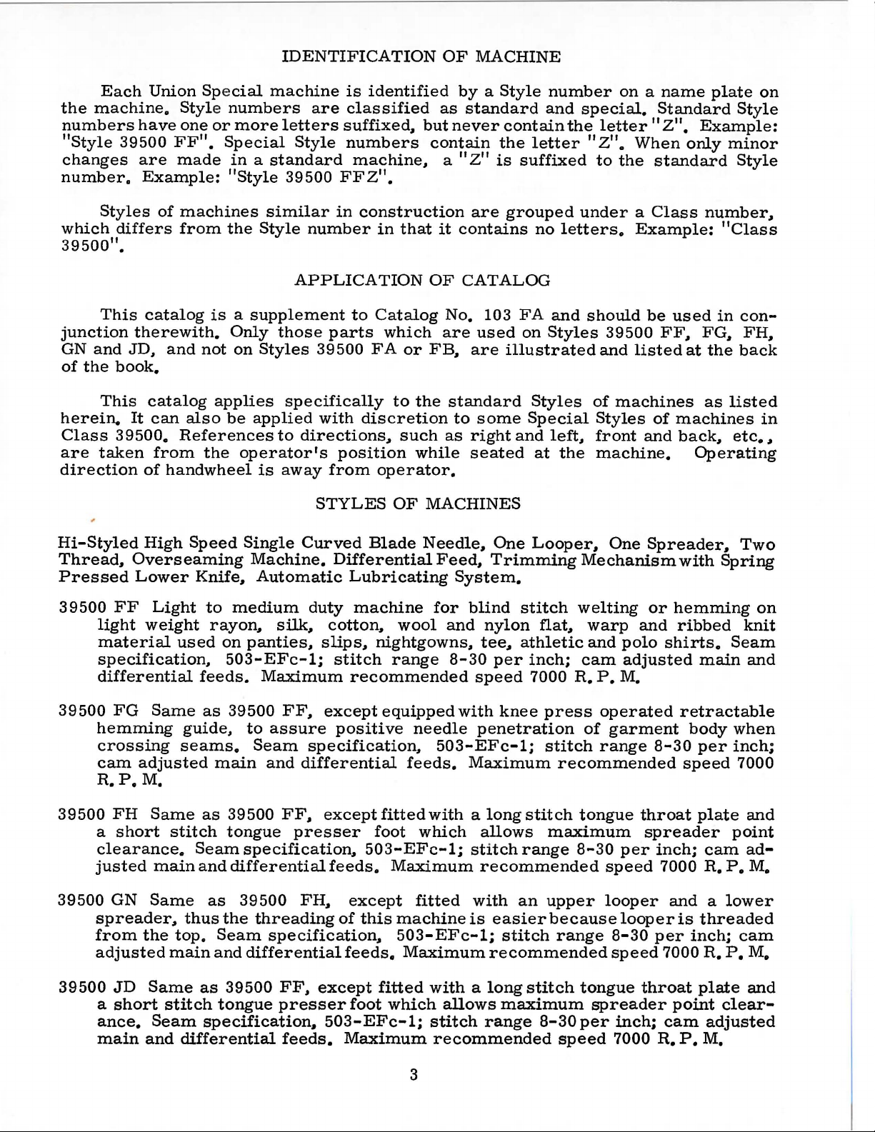
Hi-Styled
Thread,
Pressed
39500
FF
light
material
specification,
differential
39500
FG
hemming
crossing
cam
R.
P.M.
39500
a
FH
short
clearance.
justed
39500
GN
spreader,
from
adjusted
High
Speed
Overseaming
Lower
weight
Light
used
Knife,
to
rayon,
on
feeds.
Same
as
guide,
seams.
adjusted
Same
main
as
stitch
Seam
main
Same
the
and
thus
top.
main
as
the
Seam
and
Single
Machine.
Automatic
medium
panties,
503-EFc-1;
39500
to
Seam
39500
tongue
specification
differential
39500
threading
differential
Curved
Differential
Lubricating
duty
silk..
machine
cotton,
slips,
stitch
Maximum
FF.,
assure
recommended
except
positive
specification,
and
differential
FF~
except
presser
..
feeds.
FH.,
except
of
specification~
feeds.
Blade
Needle
for
wool
nightgowns
range
equipped
needle
feeds.
fitted
foot
with a long
which
503-EFc-1;
Maximum
fitted
this
machine
503-EFc-1;
Maximum
..
One
Feed,
Trimming
System.
blind
and
nylon
..
tee.,
8-30
per
speed
with
knee
penetration
503-EFc-1;
Maximum
allows
stitch
recommended
with
is
easier
stitch
recommended
Looper~
Mechanism
stitch
athletic
inch;
7000
flat..
welting
warp
and
cam
R.
P.
press
of
stitch
recommended
stitch
tongue
maximum
range
an
8-30
upper
because
range
One
Spreader,
or
and
polo
adjusted
M.
operated
garment
range
8-30
throat
spreader
per
inch;
speed
looper
looper
8-30
per
speed
Two
with
Spring
hemming
ribbed
shirts.
knit
Seam
main
retractable
body
speed
per
when
inch;
7000
plate
point
cam
7000
R.
P.
and a lower
is
threaded
inch;
7000
R.
cam
P.
on
and
and
ad-
M.
M.
39500
JD
a
short
ance.
main
Same
stitch
Seam
and
differential
as
39500
tongue
FF,
presser
specification.
feeds.
except
foot
fitted
which
503-EFc-1;
Maximum
with a long
allows
stitch
range
recommended
3
maximum
stitch
8-30
speed
tongue
spreader
per
inch;
7000
throat
point
cam
R.
plate
adjusted
P.
M.
and
clear-
Page 4
OILING
CAUTION!
filled
straight
should
before
mineral
be
Machine
sight
gauge
gauge
lines
Machine
main
reservoir
The
It
is a magnetic
have
entered
Each
number
size
sured
number
of
all
denotes
number,
in
and
needles
Oil
beginning
oil
used.
is
fill
on
front
when
machine
is
automatically
filled.
drain
plug
screw
the
crank
Union
Special
the
stamped
thousandths
size
number
packaged
was
drained
to
operate.
of a Saybolt
ed
with
of
machine.
is
Check
screw
is
designed
case.
needle
kind
of
shank,
on
the
of
an
inch
represent
and
from
viscosity
oil
at
spring
Red
stationary.
lubricated.
oil
daily
located
to
accumulate
It
should
has
point,
needle
midway
sold
by
machine
Oil
capacity
of
cap
bulb
on
No
oiling
before
at
back
be
removed
NEEDLES
both a type
length,
shank,
denotes
between
the
complete
Union
Special.
when
of
90
to
in
top
oil
level
the
morning
of
machine
possible
number
groove,
shank
symbol
shipped,
Class
125
seconds
cover.
indicator
is
necessary,
foreign
and
cleaned
and a size
finish
largest
and
39500
Oil
start;
near
diameter
eye.
which
so
reservoir
is
at
100°
level
should
other
add
oil
bottom
materials
periodically.
number.
and
other
of
Collectively,
is
given
six
ounces.
Fahrenheit
is
checked
show
than
as
required.
edge
which
details.
blade,
on
must
between
keeping
of
base.
may
The
type
The
mea-
type
the
label
be
A
at
These
FG, FH,
groove,
036,
040,
To
sample
label.
A
Selection
Thread
mation.
Success
of
needles
tion
for
than
three-quarters
Release
Fig. 1 or
ting
direction
wrench
turn.
Again
machines
GN
and
spotted
044,
have
needle
needle,
complete
of
should
pass
in
packaged
producing
pressure
1A)
and
until
No.
21388
turn
use a curved
JD
is
and
chromium
049,
054
orders
or
type
order
proper
freely
the
operation
under
highest
of a century.
on
swing
needle
AU,
handwheel
type
154
and
060.
promptly
and
size
would
needle
through
of
our
brand
quality
CHANGING
presser
presser
is
at
furnished
until
blade
GAS.
plated,
number
read:
size
should
needle
Union
name,~
needles
foot
arm
its
lowest
with
needle
needle.
It
is
available
and
should
"1000
be
eye
Special
in
NEEDLES
by
turning
(U)
out
machine,
is
at
Standard
standard
in
accurately
be
Needles,
determined
in
order
machines
materials
presser
of
position.
point
of
loosen
high
position,
needle
length,
sizes
022,
filled,
forwarded.
Type
154
by
to
produce a good
can
which
and
foot
Turn
travel.
needle
for
Styles
single
an
the
be
is
grooved,
025,
empty
Use
GAS,
size
secured
backed
027,
description
Size
of
workmanship
release
handwheel
Using
hexagonal
clamp
withdraw
needle.
39500
struck
029,
package,
027".
thread
used.
stitch
only
by
by a reputa-
for
more
bushing
in
(AG,
opera-
socket
nut
about
FF,
032,
a
on
for-
use
1/4
To
left,
insert
position,
nut.
Return
replace
turn
needle,
needle
handwheel
presser
in
arm
leave
holder
until
(U)
needle
until
holder
to
holder
it
rests
is
position
against
again
and
at
high
at
its
re-lock
stop
low
(AG).
4
position
pin.
point
presser
and
with
Keeping
of
travel,
foot
the
needle
then
release
flat
in
tighten
bushing
to
the
this
Page 5
li]
Tension
~~
Tension
II
Tension
[;]
Tension
IIJ
spring
O
Tension
~~
Tension
n
Tension
Nut
Spring
Spring
Post
Shield
Discs
Post
Disc
Ferrule
~
...
.-:-':
:
~:~---
Slot·:
Felt
!'41~~
:~
''·
.. '
,..
. ' _
·.
·~-:
_..,
.-
f
,
~:;)
Thread
Cl"\\
-
Eyelet
0
r.IJ
m
Lower
(ii
Fabric
Frame
D
(g
Presser
Front
Thread
Thread
Looper
Guard
Looper
Guide
Guide
Thread
Eyelet
Presser
Release
..
Needle
Thread
Top
Upper
u
...-.
Foot
Bushing
Cover
Thread
Looper
Tube
Assembly
Eyelet
Fig.
1
5
Page 6
(;]
Tension Nut
(~Te
II
[!]
IIJ
O Tension
[I
(I
fiJ
nsion
Tension Spring
Tension
spring
Tension
Tension
Front
Spring
Post
Shield
Discs
Post
Disc
Thread
Fer~
~~~
-..:
~
Slot :
Felt ·
..
Guide
~
lli
liJ
IIJ
ID
Auxiliary
Upper
Presser
Fig.
lA
Looper
Looper
Ar
Thread
Thread
Eyelet
lr.li~:,~!
Top
Needle
.,
Upper
ead
Cover
Thread
Looper
Tube
Assembly
Eyelet
6
Page 7
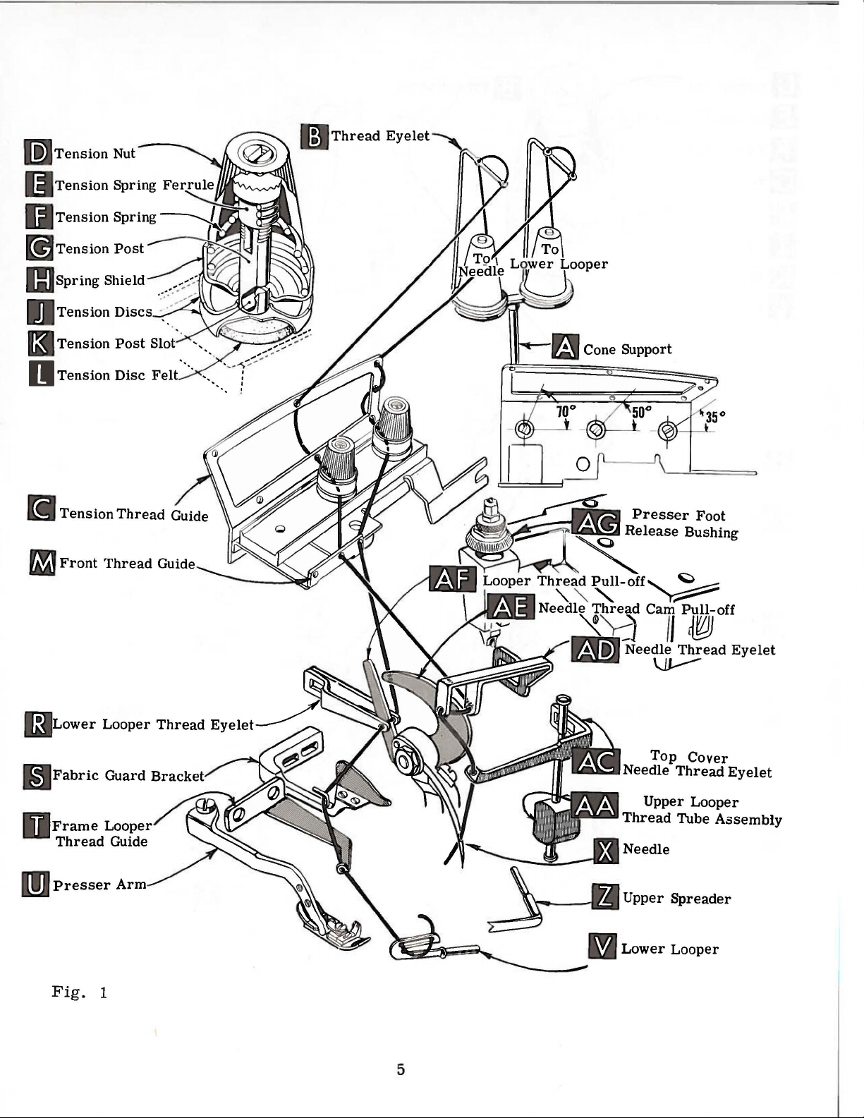
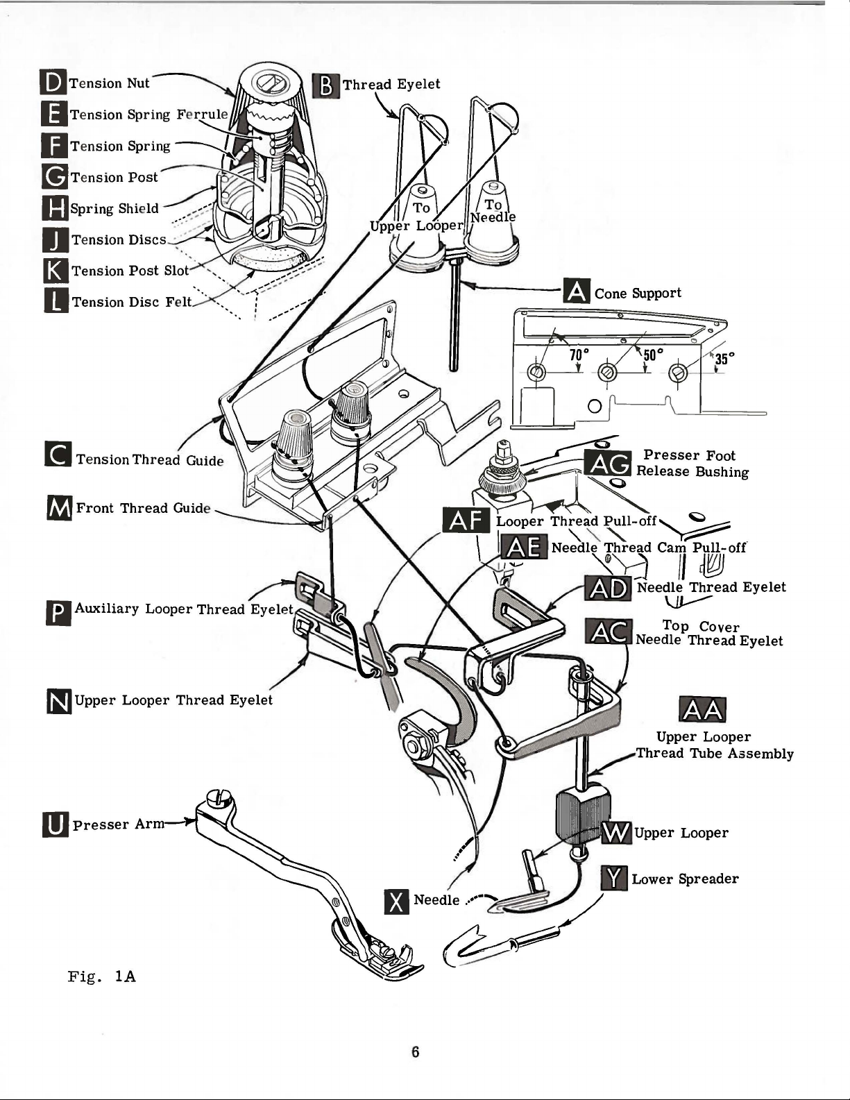
CONE
SUPPORT
After
through
Next.
thread
it
guide
continues
Onlypartsinvolv
Parts
It
are
will
sequence
upper
looper
NOTE:
for
Style
Before
direction
turning
tension
Be
presser
sure
discs
thread com
the
back
is
threaded
hole
through
(C). then
between tension
placed
in
their
simplify
of
threadin
on
Style 39500
Use
Fig. 1 for
39500
GN.
beginning
until
the
(J)
needle
foot
release
threads,
and
es
of
e
din
the
g
to
in
the
(X)
from
thread
through
cone
the
discs
eyelet,
appropriate
the
(J)
threadingare
relative
threading
lower
GN
looper
first.
threadingStyles
thread,
is
at
swing
high
bushing
as
they
tension
post
on
cone
then
support
down
upper
lower
through
holes
slot
THREADING
shownin
positions
of
these
on
Styles
Then
thread
39500
cloth
position,
(AG)
come
from
slots
and
(K)
(A.
Fig. 1 or
through
holes
from
(K)
and
the
from
back
on
threadingdiagram(Fig.
for
clarity.
ma
chines
plate
release
swing
the
in
39500
FF,
open,
tension
tension
to
the
needle.
FG,
turn
pressure
presser
posts
FF,
thread
1A)
front
front
to
front.
through
follow
FG,
FH
a~d
handwheel
arm
(U)
guide,
(G).
it
is
thread
to
back
Then
thread
the
recommended
FH
and
JD;
use
in
on
presser
out
of
are
brought
eyelet
in
tension
thread
guide
1
and
1A).
JD
or
Fig.
operating
foot
position.
between
up
(B).
(M).
the
1A
by
Double
(R,
Fig.
off
(AF).
guide
the
way
looper
Double
Turn
handwheel
through
of
upper
NOTE;
looper
down
through
down.
Turn
highest
thread
cover
TO
1)
Lead
(T).
Turn
to
the
can
be
auxiliary
looper
thread
thread
then
handwheel
position.
eyelet
needle
THREAD
end
of
from
thread
handwheel
left,
threaded
end
of
until
thread
must
tube
thread
insert
(AD)
thread
thread
right
behind
then
TO
thread
point
looper
pass
assembly
tube
thread
in
Insert
under
eyelet
LOWER
and
lead
to
left.
fabric
in
operating
thread
through
easily
THREAD
and
lead
of
upper
thread
eyelet
in
(N)
front
assembly
through
TO
operating
needle
neck
(AC).
LOOPER
it
Note;
guard
if
tweezers
UPPER
it
through
looper
eyelet
from
of
looper
(AA.
lead
upper
THREAD
direction
thread
of
top
Thread
(Styles
through
thread
bracket
direction
both
eyes
are
LOOPER
(W
(P)
from
left
thread
thread
(AA).
looper
THE
from
cover
needle
both
must
left
Fig.
to
right
Pull
until
right
casting,
in
39500
eyes
pass
in
(S)
and
until
from
left
heel
left
hand.
(Style
eyelet
back
1A)
to
of
is
.
pull-off
under
thread
eye
from
NEEDLE
needle
to
left.
from
front.
FF,
of
lower
front
through
of
to
39500
thread
all
the
front,
(AF).
neck
out
bottom
front
(X.
through
then
down
FG,
FH,
looper
of
looper
frame
lower
right.
GN)
guide
way
then
After
of
top
to
back.
Fig. 1 or
both
through
JD)
thread
thread
looper
looper
Left
eye
(M,
left.
Lead
through
pulling
cover
of
tube;
1A)
eyes
eyelet
thread
(V)
of
Fig.
thread
both
up up
casting
push
is
of
needle
hole
pull-
is
all
lower
1A).
eyes
par
and
tube
at
its
in
top
The
tension
proper
amount
nuts
stitch
of
tension
(D.
Fig. 1 or
formation.
on
lA).
THREAD
needle
Tension
and
TENSION
looper
on
threads
7
threads
should
is
regulated
be
only
by
two
enough
knurled
to
secure
Page 8
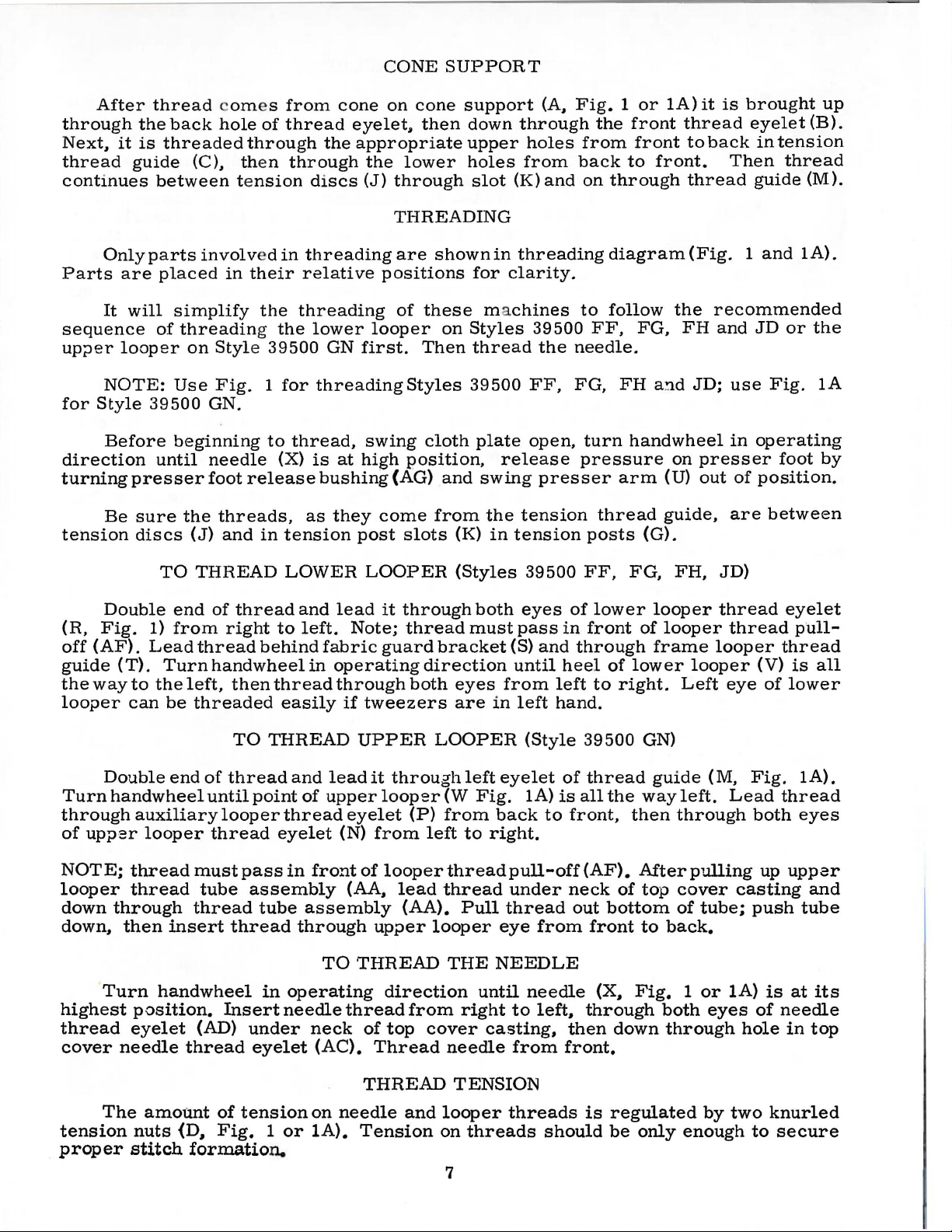
PRESSER
FOOT
PRESSURE
Feed
mately
39500
per
of
eccentric
eccentric
39540
of
will
GN
inch.
the
B-7.
stitches
be
Fig.
main
2
eccentrics
14
stitches
the
It
will
is
is
obtainable
shipped
per
eccentrics
be
noted
feed
Minor
No.
No.
with
eccentric
39540
39540
numbers
above
used
inch
that
B-8.
B-9
when
Sufficient
formly
increase
loosen
Adjusting
creases
pressure
tighten
plate.
approximately
of
(C).
in
these
have
is
of
using
combinations
should
or
lock
pressure.
lock
position
adjusting
FEED
machine
on
Styles
been
on
Styles
No.
On
Style
while
the
part
that
presser
be
maintained.
decrease
nut
(A.
screw
adjusting
selected
39540
that
eccentric.
has a right
nut
(A).
locking
1 I 3 2
inch
screw
ECCENTRICS
have
39500
39500
39500
symbol ,indicate
of
FF.
to
FF.
B-14
GN
of
the
eccentrics.
foot
amount
Fig.
loosening
2)
hand
screw
With
(B).
Unless
presser
nut
(C)
to
1 I 16
Set
been
FG.
produce
FG.
while
the
part
differential
otherwise
pressure
Should
of
pressure
and
turn
decreases
(B)
so
inch
cap
selected
FH
approximately
FH
that
approximately
adjusting
thread.
has
foot
that
its
from
(D)
to
and
and
JD.
of
the
number
feed
to
feed
it
be
necessary
on
presser
so
tightening
pressure.
been
specified.
properly
resting
under
the
against
produce
JD.
while
the
part
differential
of
the
eccentric
work
screw
on
throat
surface
top
surface
locking
approxi-
on
9
stitches
number
main
is
the
number
machines
uni-
to
foot.
(B).
in-
When
set.
is
nut
Style
feed
feed
No.
Generally
of
stitches
and
direction
Following
6,
7, 8,
Only
Additional
order
number
stitches
move
knife
guide
should
needle
17
or
driving
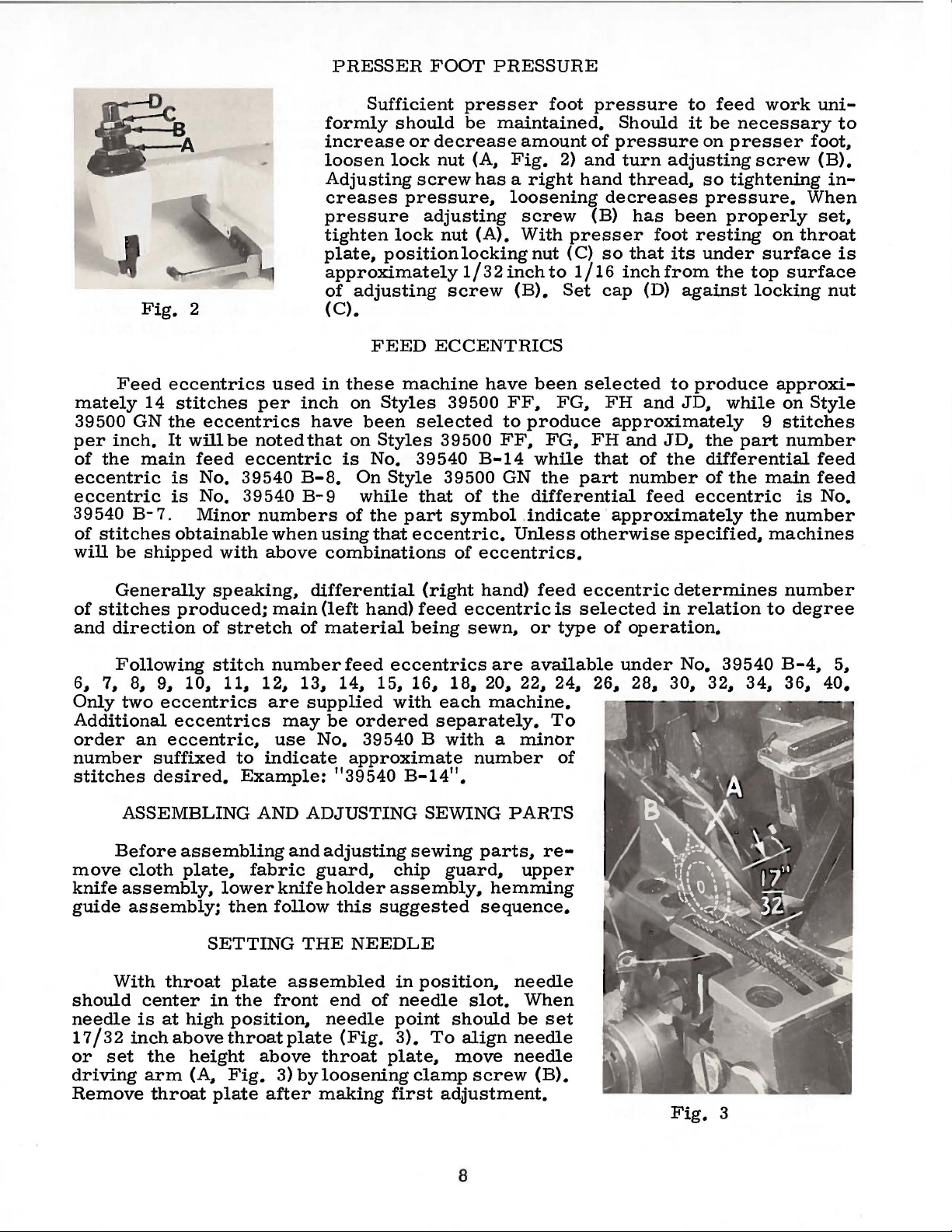
Remove
two
an
suffixed
desired.
ASSEMBLING
Before
cloth
assembly,
assembly;
With
center
is
I 3 2
inch
set
the
arm
throat
speaking.
produced;
of
stretch
stitch
9,
10,
11,
eccentrics
eccentrics
eccentric,
assembling
plate,
lower
then
SETTING
throat
in
at
high
position,
above
throat
height
(A,
Fig.
plate
main
number
12, 13,
are
may
use
to
indicate
Example:
AND
and
fabric
knife
follow
plate
the
assembled
front
plate
above
3)
after
differential
(left
hand)
of
material
feed
14, 15,
supplied
be
No.
"39540
ADJUSTING
adjusting
guard,
holder
this
THE
end
needle
(Fig.
throat
by
loosening
making
eccentrics
ordered
39540 B
approximate
assembly,
suggested
NEEDLE
of
plate,
first
(right
feed
being
16,
with
B-14".
SEWING
sewing
chip
in
position,
needle
point
3).
To
clamp
hand)
eccentric
sewn.
are
18.
20, 22, 24, 26, 28, 30.
each
separately.
machine.
with
guard,
adilustment.
a
number
parts,
hemming
sequence.
slot.
should
align
move
screw
minor
PARTS
upper
needle
When
be
needle
needle
feed
or
available
(B).
is
type
To
of
re-
set
eccentric
selected
of
operation.
under
determines
in
relation
No.
39540
32,
Fig.
3
34,
number
to
degree
B-4.
36,
5.
40.
8
Page 9

SETTING
At
Styles
on
Style
spreader
point
using
looper
Now
THE
this
NEEDLE
point,
39500
39500
at
left
3/32
inch
looper
or
spreader
assemble
FF,
GN
end
from
gauge
No.
differential
(Con 1t)
insert
FG,
into
of
its
lower
FH
bar
stroke,
center
21225-3/32.
deflecting
or
JD
(B).
of
needle.
(front)
looper
or
With
set
looper
needle
Do
feed
(A,
Fig.
lower
lower
looper
or
(Fig. 4 or
not
have
Tighten
dog.
4)
spreader
spreader
4A)
lower
nut
(C).
on
or
Fig.
Set
rear
possible.
looper
holder;
or
but
ward • 002
rear
ference
or
needle
between
spreader.
4
needle
without
spreader
still
....
in
004
guard.
rear
SETTING
guard
interfering
or
movement
position
inch.
Screw
Make
needle
THE
Now
looper
into
the
ward
from
Assemble
is
springing
as
possible
and
set
no
interference
(A,
Fig.
with
to
deflect
(B)
sure
there
guard
LOWER
finish
or
spreader
needle
rear
SETTING
needle
to
front
needle
SETTING
5)
as
either
of
lower
needle
is
used
is
no
and
lower
LOOPER
lower
moves
scarf
guard
THE
front
needle
off
needle
without
guard.
between
THE
high
lower
knife
to
inter-
looper
OR
looper
(A,
Fig.
surface
FRONT
guard
back
guard~
After
needle
REAR
as
for-
set
LOWER
or
spreader
to
the
right,
6)
until
another • 002
NEEDLE
(C,
set
touching.
this
guards
NEEDLE
Fig.
SPREADER
adjustment.
its
the
GUARD
Fig.
front
Screw
5).
needle
(D)
setting,
and
differential
GUARD
4A
point
needle
- •
004
When
guard
is
make
should
springs
inch.
lower
used
sure
As
be
looper
as
to
adjust
there
feed
lower
set
for-
close
is
dog.
Fig.
holds
around
allows
spreader
its
holder
Preliminary
stroke,
shank
should
back
extend
As
spreader
spreader
spreader
with
lower
approximately • 002
looper
Continue
end
of
its
travel.
5
shank.
to
Setting:
of
1/32
should
(Fig.
turning
in
its
Screw
be
rotated
holder
vertical
to
moves
pass
8).
the
Atthis
SETTING
Insert
holder,
(
Cg
and
Fig.
or
When
spreader
should
(Fig.
1/16
from
just
inch
right
behind
inch
handwheel
position~
THE
39500
spreader
permits
7)
on
adjusted
be
7).
Top
above
to
left~
the
clearance
until
the
lower
UPPER
FF,
(A,
spreaderto
collar
laterally.
is
at
the
set
to
end
the
holder
the
eye
of
between
spreader
point
9
SPREADER
FG~ FH~
Fig.
holds
7)
in
spreader
right
position
of
spreader
(Fig.
Vee
notch
the
lower
sprea-der
is
of
the
JD)
its
holder.
be
pushed
end
of
spreader
shank
7).
of
looper,
at
the
spreader
(STYLES
in
holder
its
the
and
left
Screw
or
in
the
Fig.
(B,
out
Fig.
or
turned
shaft,
6
7)
and
Page 10

SETTING
THE
UPPER
SPREADER
(STYLES
39500
FF,
FG,
FH,
JD)
(Continued)
should
approximately
should
•
002
is
of
center
inch
extend
Fig.
As
upper
pass
inch
Continue
at
the
the
looper
line
above
7
behind
clearance
left
of
the
about
112
looper
turning
end
of
should
the
needle
top
5132
inch
rubs
and
same
clearance
(Fig.
is
set
looper
moves
the
lower
between
the
its
extend
and
of
the
inch
to
above
at
to
handwheel
travel.
throat
the
Now
check
the
back
rotate
adjustments,
8).
SETTING
Insert
the
right
position
shank
from
spreader,
spreader
5132
should
the
left
top
of
setting
of
spreader,
spreader
between
THE
upper
end
upper
should
right
with
until
At
this
inch
be
approximately
plate
(Fig.
of
the
centerline
the
throat
between
pull
holder
in
opposite
spreader
UPPER
looper
of
extend
to
and
the
position
to
in
its
stroke,
looper
left
the
approximately
lower
upper
the
left
9A).
of
the
plate
spreader
forward a short
and
LOOPER
its
shank
1 I 16
looper
looper.
looper
the
of
3 3 I 6 4
(Fig.
spreader
movement,
needle.
holder.
upper
back
to
3 I 3 2
point
the
out
(STYLE
looper
needle
9).
and
of
Reset
When
of
vertical.
inch
and
needle.
its
holder
distance.
will
to
lower
39500 GN)
the
upper
holder
above
the
should
If
needle
slightly
These
reduce
looper
looper
should
Top
end
holder.
be
the
be
of
Now
Make
UPPER
between
~
,
fir1~
"(
T,
, -;.'
I
check
adjustment
SPREADER,"
the
l
.
'
..
•. ·
2 \' '
-•
..
:4.;a
·.~
Fig.
Replace
sembly~
(B)
seats
lower
its
upper
plate
knife.
is
necessary
tighten
against
knife
corner.
surface.
Lower
setting
upper
..
·~·
'
9
lower
screw
the
and
holder
Lower
Adjustments
knife
when
between
as
indicated
except
looper
Now
feed
of
the
sighting
throat
surface
or
lowers
The
appear
in~
pin
3 f 64
flush
knife
(A,
throat
assembly
is
spring
width
and
(C).
inch
with
holder
knife
of
upper
under,
the
the
SETTING
assemble
Set
all
teeth
plate.
above
in
SETTING
trim
across
by
rotating
the
feed
place.
above
surface
Fig.
plate
(D)
are
made
pressed
all
Feed
dogs
assembly.
11)
is
looR.er
setting
needle.
main
feed
lie
in
the
teeth
dogs
feed
back
throat
is
end
should
plate.
Now
the
of
throat
THE
so
that
mounting
obtained
should
with
against
changed.
and
SETTING
relationship
FEED
dog
set
throat
LOWER
be
DOGS
(back)
(A,
the
same
with a straight
should
tilting
of
feed
be
set
Screw
the
main
plate~
plate.
In
replacing
when
bracket
when
set
with
hexagonal
upper
needle.
THE
is
feed
dog
B~
C,
plane.
now
adjusting
bar.
level
(E)
and
and
KNIFE
the
face
(C)
the
knife
cutting
head
knife,
(B,
Fig.
Fig.
be
a
10)
This
edge.
leveled
pin
at
the
locks
differential
chaining
the
lower
of
the
free
lateral
is
manually
edge
screw
so
no
Fig.
so
can
(D).
time
feed
flange
flush
which
lateral
8
10)
the
be
Now
with
This
the
tilting
feed
feed
knife
motion
and
chaining
top
surfaces
checked
assemble
throat
pin
teeth
holder
pressed
with
holds
adjustment
dog
dog
on
plate
raises
first
adjust-
teeth
teeth
sleeve
of
throat
lower
by
as
the
at
..
10
Page 11

SETTING
THE
LOWER
KNIFE
(Con 1t)
knife
knife
feed
dog;
Lower
knife
holder
Set
the
desired
to
the
needle,
Fig.
eccentrics
while
the
shaft.
9A
used.
inner
may
width
lock
(right)
be
secured
the
Fig.
most
its
not
The
and
trim,
holding
when
Outer
of
trim
lower
SETTING
Replace
11)
in
clockwise
stroke,
less
than
chain
slightly
After
screw
block
upper
SETTING
Length
(left)
eccentric
eccentric
in
any
by
measuring
knife
THE
upper
position,
front
1/64
guard
back
upper
(J)
(K)
knife
of
stitch
(B)
position
holder
UPPER
knife
setting
position
cutting
inch
should
from
knife
should
in
is
replaced.
THE
(A,
actuates
by
from
shaft
with
KNIFE
assembly.
nut
against
edge
below
be
set
the
cutting
has
be
place.
STITCH
is
determined
Fig.
the
tightening
the
right
screw
Clamp
(G)
to
upper
of
upper
cutting
down
against
edge.
been
set
tightened
This
will
LENGTH
by
12)
actuates
differential
screw
edge
(E).
hold
knife.
knife
edge
for
proper
to
lock
simplify
the
main
(front)
(E)
against
of
the
upper
clamp
of
the
knife
(H)
At
bottom
should
lower
upper
extend
knife.
width
upper
resetting
combination
(rear)
feed
lower
(F,
in
its
of
knife
of
knife
of
feed
dog.
In
assembling
not
to
damage
To
change
(E).
Turn
front.
Using
eccentrics
wheel
and
back
If
eccentrics
washer
connection
Assemble
presser
ition
to
back)
The
in
with
in
portant
and
align
and
front
presser
front
throat
that
needle
presser
throat
plate.
presser
with
throat
shaft
handwheel
hooked
as
shown
and
(D)
(H).
the
arm
into
set
the
holes
flat
on
edge
foot
must
edge
plate.
the
foot
foot
be
can
plate
feed
or
feed
eccentrics,
forth
are
from
Then
presser
sewing
presser
(front
throat
of
needle
be
of
needle
It
is
bottom
flat
If
necessary,
be
realigned
slots
eccentrics,
key.
in
Tighten
operating
eccentric
and
withdraw
slightly
'
unusually
shaft
(E),
continue
SETTING
foot
pos-
foot
and
plate.
hole
aligned
hole
also
im-
of
the
on
the
by
remove
extractor
during
tight
it
may
as
originally
to
presser
be
sure
nut
(C)
nut
direction
(F),
eccentrics.
extraction.
fitting,
THE
in
be
helpful
PRESSER
arm.
hubs
are
securely.
(C)
and
until
key
supplied
It
may
addition
to
remove
suggested.
FOOT
With
Fig.
facing
washer
slot
with
be
necessary
to
removing
needle
10
each
in
other.
(D)
from
eccentric
machine,
nut
(G)
in
hi.gh
Be
end
is
reach
to
move
nut
(C,
and
feed
position,
careful
of
shaft
toward
behind
hand-
Fig.
driving
swing
13)
11
Page 12

SETTING
THE
PRESSER
FOOT
(Cont.)
thread
drawn
thread
tongue.
thread
of
stroke,
that
needle
thread.
Fig.
control
on
needle
should
Stitch
is
pulled
position
thread
11
as
be
tends
on
follows:
down
just
tight
to
the
needle
cam
Usually
stroke.
enough
pull
up
stroke.
thread
pull-off
shifting
move
clamp
shaft
screws
collar
does
ing
foot
spreader
should
lifter
This
locked
fabric
turn
highest
material,
At
down
(AE)
the
screw
to
The
(B)
not
is
unlocked.
Adjust
can
be
lever
adjustment
guard
handwheel
W
hi
all
top
of
to
feed
slightly
With
eyelet
just
the
foot
shaft,
the
left
and
clamp
foot
secure
bind
and
lifter lever
be
raised
will
from
before
with
nut
and
position.
NEEDLE
1 e
sewing
check
needle
needle
chain
if
needle
(AD,
contacts
lifter
loosen
(G)
and
or
right
screw.
lifter
the-shaft.
rise
no
permi.t:
1/16
the
should
(F).
cloth
until
upper
needle
thread
stroke,
off
stitch
excessive
at
bottom
Fig.
1)
needle
lever
collar
then
as
lever
shaft
screws
shift
required.
arm
Be
whenpresser
stop
screw
higher
then
to
1/8
lock
inch
presser
be
made
Re-assemble
plate.
To
knife
THREAD
on
is
so
(H,
(B,
the
foot
Re
(A,
Fig.
sure
than
foot
(C)
the
free
foot
with
the
release
so
upper
nut
motion
begins
screw
the
assemble
assembly
CONTROL
Fig.
Fig.
lift
er le ver
tight
en
14)
presser
that
looper
(D).
chip
chip
reaches
14).
To
14)
and
collar
and the
arm
bush
presser
or
Ther
of
foo
to
rise.
(E)
and
guard,
guard,
its
-
e
t
LOWER
With
thread
eyelet
THREAD
Before
Moderate
SKIPPING:
1.
Recheck
LOOPER
material
(R,
Fig.
proceeding.
change
For
under
Fig.
presser
1)
13
TENSIONS
balance
in
these
occasional
lower
looper -needle
THREAD
back
and
both
tensions
SPECIAL
skipping,
CONTROL
foot,
set
down
thread
extreme
(R)
should
NOTE:
speed,
ward
arm
Frame
with
its
of
heel
looper
tensions
will
not
ADJUSTMENTS
check
lower
far
enough
is a little
left
If
move
slightly
binder
eyelet
eyelet
is
at
marked
and/
setting.
looper
so
slack
position.
be
about
looper
thread
lower
at
an
screw.
looper
thread
approximately
of
looper
extreme
to
give a normal
ly
affect
or
ad~ust
See
when
Lower
spreader
looper
horizontal.
breakage
looper
angle
thread
away
guide
1/8
(V)
left
end
the
purl.
as
outlined
'Setting the
Fig.
thread
occurs
eyelet
from
(T)
should
inch
at
the
of
its
travel.
appearing
below:
Needle"
12
reaches
eyelet
at
(R)
the
needle
be
to
the
time
stitch.
Page
its
high
up-
set
right
lower
8.
12
Page 13

2.
Reche
Page
ck
9.
spreader
SPECIAL
-
lower
ADJUSTMENTS
looper
crossing.
(Con't)
See
"Setting
the
Spreader",
3.
Be
sure
With
lower
looper
horizontal
front
to
back
heck
far
enough
Fig.
machine
thread
thread
and
location.
clearance
left
past
14
is
threaded
tensions lig
eyelet
in
the
middle
between
needle.
ht,
set
(R)
about
of
its
needle
Setting 1 and 2 should
fully.
that
reposition
1)
by
holes
(AF).
thread
distorting
CAUTION:
slightly
left
position,
side.
according
and
spreader.
If
it
skip
is
lowering
in
close
After
tension
stitch.
slack
STARTING
to
threading
can
be
definitely
lower
it
to
this
as
Looper
as
or
See
determined
not a needle
looper
slightly
bend
in
change.
much
thread
spreader
stitch
will
TO
diagram
that
thread
be
and
spreader
made
by
eyelet
bringing
quite
appearance
looper thread
increase
as
possible
must.
reaches
appear
as
its
tight
OPERATE
(Fig.
1.
moves
care-
loop
(R,
eyelet
pull-off
looper
without
before.
extreme
on
Page
skip.
Fig.
be
top
5).
Operate
presser
chain
forms
freely.
SETTING
SUPPORT
Assemble
support
support
(A,
Fig.
justing
(C)
even
side
throat
so
with
of
screw
that
plate.
When
slightly
screw
(D,
to
located
Fig.
Under
differences
amount
justing
edge
screw
of
the
guide
all
machine
foot
in
and
THE
bracket
bracket
15).
(B),
the
and
the
right
the
edge
the
right
towards
15).
normal
in
material
movement
screw
support
the
way
slowly.
place;
moves
HEMMING
BRACKET
the
hemming
onto
the
by
means
With
left
set
side
the
the
parallel
feed
guide
of
parallel.
the
conditions.
and
which
bracket
out
against
with
make
off
sure
tongue
GUIDE
guide
lower
of
knife
screw
knurled
edge
of
to
slot
tip
its
the
is
guide
tip
right
in
in
This
front
the
thickness.
pressure
presses
(D,
the
ad-
is
the
this
position.
adjustment
of
the
edge
For
applied
against
Fig.
edge
hinge
guide
example,
the
15).
guide
the
block
is
spring
to
the
spring
Removing
prevents
front
can
and
edge
Fig.
or
be
made
edge
pressed
as
in
going
guide
located
this
movement
15
leading
by
guide
to
tip
in
spring
edge
positioning
support
compensate
over
is
the
seams.
controlled
hinge
and
turning
of
the
edge
should
the
bracket
for
by
block
guide.
be
stop
the
The
adand
the
13
Page 14

FOR
STYLE
39500
FG
ONLY
Mount
screws
hemming
should
to
the
be
right
the
retractable
(B).
Attachthekneepress
guide
positioned
as
support
to
shown
bracket
the
in
the
edge
guide
Fig.
with
extreme
illustration.
lever
16
chain
screw
left
bracket
to
the
when
only
lever
(D).
in
normal
when
(A.
arm
The
making
Fig.
(C)
16)
and
adjustable
operation.
repairs
onto
the
stop
The
the
casting
lever
lever
slide
on
garments.
arm
slide
is
with
to
the
(E)
moved
Adjust
that
the
fabric.
and
the
just
the
guide
is
hanging
in
the
hinge
Adjust
sitioning
thickness
into
place.
the
stitches
Adjust
edge
guide
stop
screw
located
guide
block
the
the
adjusting
of
the
edge
guide
are
the
overhanging
corresponds
(F)
at
the
can
be
and
amount
seam
FINAL
(C.
located
for
center
locked
edge
of
stop
to
be
ADJUSTMENT
Fig.
in
the
into
guide
FOR
retraction
screw
15)
the
folded
guide
with
(E)
the
overhanging
of
the
position
support
STYLE
of
(G).
crossed.
OF
by
turning
edge.
so
that
thickness
guide
edge
guide
by
tightening
bracket
39500
the
edge
The
position
The
locking
HEMMING
the
knurled
yet
do
the
space
of
the
material
so
that
vertically.
the
(D).
FG
ONLY
guide
of
nut
bracket
the
(H)
GUIDE
adjusting
not
show
between
the
tip
locking
screw
should
on
to
be
of
If
desired.
screw
(F.
will
then
screw
the
face
its
guiding edge
hemmed.
the
overhanging
the
(G)
Fig.
16)
depend
be
tightened
(B)
so
of
the
Ad-
over-
located
by
po-
on
the
14
Page 15

SETTING
THE
HEMMING
JD
WITH
GUIDE
SUPPORT
IMPROVED
BRACKET
HEMMING
FOR
GUIDE
STYLES
ASSEMBLY
39500
GN
AND
ment
be
ing
and
set
the
located
et
(E~
If
remove
then
replace
screw
against
Fig.
the
by
removing
17
pressure
screw
in
the
hinge
Fig.
17 ).
movement
lock
screw
set
is
tightened
set
screw.
which
Replace
of
screw
against
NOTE:
Assemble
knife
the
knurled
the
left
of
the
When
leading
adjustment
18)
located
support
Under
to
compensate
For
example~
applied
lock
screw
presses
block
and
lock
the
edge
(B~
Fig.
and
pin
Be
sure
then
support
side
right
the
edge
can
bracket
normal
to
(B~
against
edge
screw
guide
18)~
lock
and
that
proceed
the
hemming
bracket
adjusting
of
its
tip
feed
slot
edge
should
be
made
towards
(E~
conditions~
for
as
in
the
edge
Fig.
the
guide
and
tighten
is
not
set
screw
screw.
lock
screw
lock
screw
as
follows:
guide
by
means
screw
is
in
guide
be
the
Fig.
the
going
guide
18)
and
spring
support
(C)~
even
the
throat
tip
with
is
slightly
by
positioning
front
of
17 ).
differences
over
tip
adjust-
and
pin~
brack-
securely.
required~
and
Be
is
then
spring;
sure
tightened
(A,
support
of
screw
set
and
plate.
in
to
the
the
the
edge
seams.
can
set
Fig.
the
parallel
this
right
the
hinge
in
the
17)
has
been
bracket
(B~
edge
position~
stop
block
guide
material
The
onto
Fig.
guide
to
the
of
parallel.
screw
and
is
spring
amount
Fig.
17 ).
(D)
the
edge
thickness.
18
loosened,
the
lower
With
so
that
right
side
front
This
(A~
Fig.
guide
loaded
of
move-
or
Adjust
that
the
fabric.
Adjust
edge
and
hemmed.
block
(E)
guide.
that
is
in
the
center
stop
screw.
FINAL
the
edge
stitches
At
this
the
overhanging
the
edge
Loosen
to
obtain
Retighten
front
of
the
are
point
screws
of
lock
edge
ADJUSTMENT
guide
(D~
located
retighten
guide
guide
set
the
(D)
screw
(C~
proper
(C)
and
screw~
guide
vertically.
OF
Fig.
in
17)
the
screw
(F~
by
folded
(A~
Fig.
corresponds
Fig.
18)
distance
(D).
Remove
so
that
the
IMPROVED
turning
edge~
Fig.
17)
with
and
between
the
17)
so
the
holding
the
lock
tip
of
the
Replace
HEMMING
knurled
yet
do
not
securely.
that
the
thickness
screw
edge
screw
overhanging
lock
screw
adjusting
show
space
(D)~
guide
(F)
and
(F)
GUIDE
on
between
of
the
now
and
adjust
guide
and
screw
the
face
its
material
move
the
overhanging
stop
is
located
tighten
(C)
of
guiding
the
screw
against
so
the
to
be
hinge
at
15
Page 16

20
r
-,
'
l
16
Page 17

The
page
but
parts
21
not
illustrated
represent
used
on
the
Styles
on
pages
parts
39500
that
FA
16,
or
18
are
FB.
and
used
20,
on
and
Styles
described
39500
on
FF,
this
FG,
page.
FH,
page
GN
19,
and
and
JD,
Unless
styles
reference
Use
described
Reference
descriptions,
Ref.
No.
1
2
3
4
5
6
7
8
9
10
11
12
13
14
15
16
17 39582 J
18
19
20 39520
21 39530 E
21A
22 22738
23 22768 B
24
25
25A 39597 A
26
27
28
29
30
31
otherwise
covered
numbers
Catalog
in
numbers
Part
No.
39501
22657
39501 K
22513
39532 D
39505 G
39505
39505
39526
39505
39505
93 A
39540
39540
39540
39540
39582
39582 H
39520
39520
39530 U
39530
39597 F
22738
39530
39560
39508 A
39508
39560
B
B
A
B
in
No.
this
indicate
AP
D-12
AL
H
H
BH
F
B-8
B-7
B-14
B-9
BR
G
H
BH
specified
this
catalog.
are
103
FA
catalog.
that
they
Lower
Upper
Lower
Upper
in
the
description,
Those
common
(Styles
are
are
Cloth
Chaining
FG------------------------------------------------
Chaining
Chaining
JD-----------------------------------------------Differential
Main
Main
FG,
Screw,
Differential
39500
Differential
39500
Main
FG,
Main
Side
Presser
Presser
Presser
FG, FH,
to
inside a bracket
component
Plate-----------------------------------------Screw,
Cloth
Screw.
Latch
Feed
Feed
Feed
Feed
Feed
FH,
for
FF,
GN------------------------------------------
Feed
FH,
Feed
Cover------------------------------------------
Spring
Rivet
Presser
Presser
Screw,
Screw,
Presser
Stitch
Stitch
Screw,
Chip
-------------------------------------------
Foot,
Foot,
Foot,
39520 G and
39520
Tongue,
39520
Tongue,
39520
Guard--------------------------------------
Spreader,
Looper,
Looper,
Spreader,
parts
Styles
39500
for
Plate
for
Spring-------------------------------------
Feed
Dog,
Dog,
JD
main
Feed
FG, FH,
Feed
Driving
JD
Driving
------------------------------------------
BH
for
for
G---------------------------------------Hand
for
JD----------------------------------------
FA,
FA
cloth
Stud
latch
Dog,
Dog,
Dog,
Dog--------------------------------marked
marked
--------------------------------------feed
Driving
Driving
---------------------------------------
for
Styles
for
Styles
for
Style
Foot
Chain
39520 H
Foot
Chain
-------------------------------------chain
tongue
Foot
Hinge
39520
chip
for
marked
for
marked
the
parts
shown
FB,
FF,
or
FB)
for
on
the
parts
Eccentric,
Eccentric,
marked
marked
of a complete
Description
plate
--------------------------------spring---------------------------
marked
marked
marked
shield---------------------------
guard
Style
----------------------------
"S",
''CN".
'U".
''CM",
''F'~
dog-----------------------------
Eccentric,
JD
-----------------------------
Eccentric,
39500
39500
39500
Shield,
----------------------------
Shield,
and
spring----------------------
Spring------------------------
''DV",
''DS",
BH
---------------------------
---------------------------39500
''CC"
Styles
39500
''E".
are
in
phantom
FG, FH,
all
picture
for
for
for
for
Style
for
Styles
for
Styles
for
Style
FF,
FH,
GN----------------------
for
for
for
for
GN
for
Style
FF,
for
Styles
used
parts
plates
Styles
Styles
for
for
FG
JD
presser
presser
presser
presser
------------------FG, FH,
on
all
views
part
Style
39500
39500
Styles
Style
39500
39500
----------------
----------------
39500
39500
GN
not
and
or
39500
39500
39500
feet
foot
foot
feet
GN
and
and
assembly.
GN
FF,
FF,
GN
JD
FF,
illustrated
have
the
bearing
JD.
FF,
GN
FH,
-------
-------
No.
No.
No.
Nos.
--------
-------
machine
no
or
indented
Amt.
Req.
1
1
1
2
1
1
----
1
1
1
1
1
1
1
1
1
1
1
1
2
1
1
1
1
1
1
1
1
1
1
1
1
1
1
1
1
17
Page 18

~8
18
Page 19

THROAT
PLATES~
NEEDLE
AND
GUARDS~
UPPER
MISCELLANEOUS
KNIFE~
LOWER
PARTS
KNIFE
PARTS
Ref.
No.
1
2
3
4
5
6
7
8
9
10
11
12
13
14
15
16
17
18
19
20
21
22
23
24
25
Part
No.
39525
39524
39524
39525
22585
39525
90
39580
88
39550
39550
39550
22559
39570
22561
39556
39578
39592
39592
39592
39568
39568
39563
39556
22798
39556
605
K
D
G
E
G
D
BA
B
T
K
J
H
L
N
v
AR-4
AR-4
AR-5
B
E
J
M
L
Needle
Throat
JD
Throat
Needle
Screw~
Needle
Screw~
Throat
Screw~
Lower
Spring
Knife
Guard
Plate~
-----------------------------------------------
Plate~
Guard,
for
Guard,
for
Plate
for
Knife
Cover
Pressure
Adjusting
Upper
Screw~
Knife~
for
Presser
Fabric
Needle
Looper
FGI
Looper
Upper
Guard~
Thread
Thread
FHI
Thread
or
Auxiliary
39500
Needle
Chain
GN
Thread
Cutting
Screw~
Chain
Screw~
for
Description
rear~
1
marked
marked
rear~
locking
for
St;r.Ie
"AM'~
"AF"~
for
Styles
side
cover------------------------
39500
for
for
39500
Styles
Styles
GN---------------
FF1 FG
front---------------------------------
needle
and
lower
Holder
guards
Lower
knife
----------------------------
Knife
holder
Support
------------------------
---------------------------------
Bracket
--------------------------------------Equalizing
Spring---------------------
Screw-------------------------------------
for
presser
Foot
Style
Tilt
for
Tension
Tension
39500
foot
tilt
Lever~
Style
for
39500
Spring------------------------
Spring~
GN----------------------
lever~
Style
for
Style
39500
GN---------------------
for
Styles
GN---------------------------------------Lower
Upper
Tension
Looper
Looper
Spring~
Thread
Thread
for
Eyelet
Eyelet1 for
Style
----------------
----------------------------------------Cam
Pull-off
-------------------------
Knife----------------------------------
for
chain
Cutter
chain
cutter
blade---------------------
Blade------------------------------
cutting
knife------------------------
39500
39500
FH
FF
FH1 JD
1
---------
39500
GN-----------
39500
39500
JD------
Style
1
1
FF
FG
GN---
GN~
--
---
1
Amt.
Req.
1
1
1
1
1
1
2
1
1
1
1
1
1
1
2
1
1
1
1
1
1
1
1
1
1
1
2
19
Page 20

20
·- ·
I
I
I
-_j
Page 21

HEMMER
GUIDES
OPERATING
ASSEMBLIES,
LEVER
OVERHANGING
ASSEMBLY
GUIDES
AND
Ref.
No.
1
2
3
4
5
6
7
8
9
10
11
12
13
14
15
16
17
18
19
20
21
22
23
24
25
26
27
28
29
30
31
32
33
34
35
36
37
38
39
40
41
42
43
44
45
46
47
48
49
50
51
52
53
54
55
56
57
58
59
60
61
62
63
64
65
66
Part
No.
29481 L
303
61303
D
39589
AC
22873
39589
AD
22799 B
22743
222 D
39589
AF
HA73 B
73
39589
AB
39589
AJ
22729 A
39503
22513
39589
AG
39589
39589
AH
79077
39568
J
39589
AL
222 D
39589
AK-1/2
39589
AK-3/4
39589
AK-1
39589
AE-1/2
39589
AE-3/4
39589
AE-1
39589
H-3/4
39589
H-1
39589
H-1/2
98
A
29481 F
39589
u
22760 A
39503
G
22565
c
39568
J
79077
22738
28-176
39589
E
39589
J
22873 B
22743
22799 E
39589
G
39589
F
77 Q
22569 c
8372 A
22593
29481 E
39589
36279
22874
39589
22726
39589
22557
61256
39589
22560
M
B
9937
K
A
N
D
G
L
A
c
c
L
c
AA
Blk.
Description
Hemmer
Overhanging
Overhanging
Overhanging
Overhanging
Overhanging
Overhanging
Overhanging
Overhanging
Overhanging
Screw,
Hemming
Screw,
Washer,
Screw,
Operating
Screw,
Guide
Screw,
Cup
Washer,
Hemming
Adjusting
Edge
Hinge
Screw,
Screw,
Hemmer
Stop
Screw,
Set
Screw,
Hinge
Hemmer
Screw,
Edge Gui
Screw,
Sleeve,
Overhanging
rlolding
Stop
Screw,
Spring,
Pi
n,
Screw,
for
Hemming
Screw,
Edge
Screw------------------------------------------------------
Edge
Screw-----------------------------------------------------Screw-----------------------------------------------------Adjustable
Overhanging Guide
Spring
Adjusting
Screw-----------------------------------------------------Hi
nge
Hinge
Overhanging Guide
Screw--------------------------------------------------
for
for
for
Operating
Spring------------------------------------------------------
Nut
--------------------------------------------------------
Screw-----------------------------------------------------Operating
Screw-----------------------------------------------------Operat
Screw-----------------------------------------------------Washer----------------------------------------------------Operating
for
Assembly,
for
edge
for
Attachment
Screw,
Guide
for
Guide
Guide
Guide
Support--------------------------
Screw,
for
for
Block
for
for edge
for
overhanging
for
-----------------------------------------------------
Screw
Block
operating lever
hemming
Lever
ing
operating
for
edge
hemmer guide
Guide
Guide
de-------------------------------------------------
for
Spring--------------------------------
for
edge
Guide,
Guide,
Guide,
Guide,
Guide,
Guide,
Guide,
Guide,
Guide,
screw
End
for
overhanging guide
for
No.
-----------------------------------------------Stop------------------------------------------
hemmer
edge
Guide
for
edge
edge
guide
overhanging guide---------------------------------
for
for
for
for
for
for 1 inch
for
for 1 inch
for
Assembly,
Guide
Screw---------------------------------------------
Hin
edge guide
------------------------------------------------Tension
Insert
------------------------------------------------
and Edge
No.
guide
Assembly,
Lever
Lever--------------------------------------------Lever
Lever
for
Styl
es
39500
guide
support
screw
for edge
overhanging
guide
guide----------------------------------------
guide
guide
Blank--------------------------------------
Bracket-------------------------------------
Slide
Link---------------------------------------lever
No.
Base
tension
Plate-------------------------------------
22729
guide
---------------------------------------
Hinge
guide--------------------
tension--------
tension
1/2
inch
3/4
inch
1 i
nch
1/2
inch
3/4
inch
3/4
inch
1/2
inch
guide,
for
ge
Spring--
----------------
Spring-----------------------------------
Base--------------------------------------
Guide
Hinge-------------------------------------
assembly,
22569
assembly-------------------------------
for
Member--------------------------------
link,
---
- -----
303----------------
--------------------
guide
support--------
guide
spring-------------
end
plate
A-----------------------------------
stop--------------------------------
Block-------------------------------
spring---------
hem, for
hem,
hem,
hem,
hem,
hem,
hem,
hem,
hem,
for
Styles
Support---------------------------
C-----------------------------------
Style
for
hinge
for
for
for
for
for
for
for
for
Styles 39500
39500
--
-----------
for
39500
Style
GN,
JD-
-----------------
---------
hinge
block-----------------
--------------------------block------------------
-
-----------------------
-
Style
39500
Style
Style
Style
Styles
39500
39500
Style
39500
Style
39500
39500
Styles
39500
Styles
FF,
FF,
FG,
-
----------------------
Style
39500
FG---------------------
39500
FG
-------
- -
-------------
--
-------------
--
---------
-
---------------
-
------------
-
-------------
--
-------------
------------------JD
------------
JD
------------
JD--------------
GN
GN
GN--------------
39500
FF,
FF,
39500
--
FG,
FF,
FG,
FH
FH
-------------
- -
----------
FG------------
-----------------
---
-----------
----------FG,
FH
FH
FG,
FH
----------
---
-
-----
-
---
---
---
---
Am
Re q .
- 1
1
1
1
1
1
1
2
2
1
1
1
1
1
1
1
1
1
1
1
1
1
t .
1
1
1
1
1
1
2
1
1
2
1
1
1
1
1
1
1
1
1
1
1
1
1
1
1
1
1
1
1
1
1
1
1
1
1
1
1
2
1
2
2
1
1
1
21
Page 22

BOOST
WI
TH
W
ORK AIDS
UNION
PRODUCTION
THESE
SPECIAL
FROM
PNEUMATIC
conventional
sci
ssor-action
positive
AIR
signed
to
remove
knit materials as
area.
cui.
FABRIC
for
Class
curls
Style
2899
Class
Style
CHAIN-CUTTER-for
39500
and
mechani
2899
UNCURLER-This
39500
from
top
fabric
B-1
39600
sm
that
makes a clean
A-1
machines, uses
and
botlom
passes
through
use
unit,
plies
air
of
sewi
on
de·
jets
flat
ng
is a durable
PNEUMATIC
operated
machines
simply by knee-touchi
CHAIN
CUTTER-
small
pneumatic
lor
installation
36200
Flatseamers. Style 2899A-6
FOOT
loot lifter
allows
the
chain
as an
lor
use
operator
ng
The
above
cutter
accesso
LIFTER-The
on
Class
to raise
an
actuating swi
photo
that
Is available
ry
uno!
lhe
shows
on
air-
39500
loot
tch.
the
Class
KNIFE
GRINDER
type knives,
nates defective garments caused by dull knives .
is
simp
sharpens strai
le a
nd
easy to operate, eli m
ght
®
AMCO
fiNfSf QUAliT
ELECTRONIC
to
move
Y
wheel
i
nsur
ing
betler
the
contro
needle
l, unoform
NEEDLE
up
or
POSITIONER&
down .•.
quality
CORPORATION
or
and
angle
i-
this
allows
increased
HEAT
DISPELLER-Union
un
it
(arrow)
is
o
il
temperature where heavy
quores
elim
inate
the
productio
an effective means
it.
Style
2899
E-1
the
necessi
operator to keep
n.
ty
of
reach ing
both
Special's
duty
hands
auxiliary
lor
reducing
service re-
for
the
hand-
on the work ,
Page 23

Helpful, aut
ci
ent
machine sewed
Sales
esting, illustrated
o
bli
gat i
horitative information
typ
es
of equi
Promotion
on
article
are the
pment
is available
Depa
rtment.
bulletins
following
for
that
:
on the
mak
from
Among
are available wi
ing vi
Union
the
most
rtua
Special's
many
eff
lly any
interthout
i·
HERE
ARE
HELPFUL
No.
240,
No.
249,
No.
250,
No.
251,
No.
252,
No.
253,
No.
254,
No. 256,
No.
259,
No.
260,
No.
262,
No. 263,
No.
264,
No.
265,
No.
266,
No.
267,
No.
268,
No.
269,
No. 271,
No.
273,
No.
610,
No.
710,
No.
730,
No.
740,
No.
750,
No.
1100,
No.
1105,
"Columbia
ing Mach i
No.
1500,
"Men's
, Women's,
"Rainwear"
"Men's
"Service
"Men's
"Overalls, Coveralls, and Dungarees"
"Men's
"Knit
"Men's
"Work
"Cotton,
"Men's
"Men's
"Women's
"Women's
"Corsets, Girdles, Brassieres"
"Children's
"Mattresses,
Upholstery"
"Awnings,
"Curtains & Drapes"
"Kiipp-it"
"MCS
"MCS
Hemmer
"MCS
"Fusing
sti
nes
Dress
Shirts
Shorts
Knit
Outerwear"
Sports
Gloves"
Bags"
Clothing"
Women's,
ForMation Uni
Automatic
"
Automatic
Presses"
"Lewis
"Button
"Alteration
tch,
Blindst
"
Blindstitch,
Mach i
itch, Saddle
Burlap,
Wear"
Wear
Canopies, Tents,
Sewers-
Children's
Shirts"
and
Pants"
and Pajamas"
Underwear"
Shirts"
Jute,
Children's
And
Wear"
Slip
Covers,
Dual
Rib-Kn
Chainstitch, Lock
nes"
Ticket
Department
and
Multiwall
High
Fashion"
Furniture
t"
Underfront
it
Cuff
Tackers"
Stitch,
Machines"
Footwear"
Jackets"
Tarps"
Machine"
and
Tie
Paper
Shirt
Clos-
BULLETINS
TO
HELP
SEWING
·
and
YOU
CATALOGS
SOLVE
PROBLEMS
®
flNtSt OUAUTT
CORPORATION
Page 24

,..o
...
...
'
0
WORLD'S
"t
L f
FINEST
QUALITY
*
INDUSTRIAL
SEWING
•
MACHINES
UNION
SPECIAL
facilities throughout
aid
you
in
the selection of the right sewing
equipment for your
Special representatives
tory trained
promptly
tion, there
and
and
is
a Union Special Representative to
serve you. Check with
ATLANTA,
BOSTON,
CHICAGO,
DALLAS, TEXAS
LOS ANGELES, CAL.
NEW
PHILADELPHIA, PA.
GA.
MASS.
ILL.
YORK, N.
Y.
maintains sales
the
world. These offices
and
service
will
particular operation. Union
and
are
service men
able
to serve your needs
are
fac-
efficiently. Whatever your loca-
him
today.
MONTREAL, CANADA
TORONTO, CANADA
BRUSSELS, BELGIUM
LEICESTER,
LONDON,
PARIS, FRANCE
STUnGART,
ENGLAND
ENGLAND
GERMANY
Representatives
industrial
and
cities
distributors
throughout
in
the
all
Important
world.
CORPORATION
400
N.
FRANKLIN
ST.,
CHICAGO,
ILL.
60610
 Loading...