

Page 1
®
INDUSTRIAL
SEWING
F
INEST QUALITY
S
TYLE
395
00A
C-
060
LEWIS
•
TY
SEWING SUPPLy
UNI 824
Lo
a ,Angeles,
COLUMBIA
E.
8th St.
CA
90021'.
MACHINES
CO.
CATALOG
No.
103AC
HIGH
CLASS
STREAMLINED
SPEED
39
500
OVERSEAMERS
MACHINE
C H'l C A G 0
f:J-
(_
COMPANY
Page 2
Catalog
(Supplement
INSTRUCTIONS
No.
to
Catalog
FOR
103
No.
AC
103
S)
The
furnish
ADJUSTING
LIST
parts
e d
at
CLASS
39500
l i
sted
list
A N D
O F
Style
AC-060
in
prices
OPERATING
PARTS
39500
this
for
catalog
repairs
are
only.
F i
R
Union
ights
Copyright
Special
R
eserved
rst
Edition
1961
by
Machine
in
All
MACHINE COMPANY
INDUSTRIAL
Printed
SEWING
CHICAGO
in
2
MACHINES
U.S.A.
Co.
Countries
February.
1967
J
Page 3
IDENTIFICATION
OF
MACHINE
the
Each
name
Union
plate.
Machines
no
letters.
standard
Style
as a suffix
construction.
This
catalog
Parts
illustrated
machines.
to
help
locate
Opposite
description,
Adjusting
39500
and
AC-060.
This
can
catalog
also
References
operator's
is
away
from
Special
similar
Example:
of a machine.
to
the
is a supplement
in
For
clarity,
39500
the
illustration
and
amount
and
operating
applies
be
applied
to
direction,
position
operator.
machine
in
construction
"39500".
standard
this
catalog
certain
AC-060
required.
specifically
with
such
while
is
identified
are
Letters
Example:
Style
identification
APPLICATION
to
Catalog
represent
39500
A,
parts.
page,
parts
instructions
to
the
discretion,
as
right,
seated
at
the
by a Style
grouped
suffixed
"39500
OF
No.
103
parts
B,
are
identified
included
standard
to
some
left,
front,
machine.
number
by a Class
to a Class
AC-060''.
to
specify
CATALOG
Sand
not
used
P
and
AF
by
represent
Styles
Special
back,
Operating
number,
should
in
parts
detail
only
of
machine
machines
etc.,
which
number
Letter''
machine
be
used
39500
are
shown
number,
areas
are
direction
is
stamped
which
indicates
Z"
is
reserved
is
of
"Special"
in
conjunction.
A,
B,
in
part
concerned
as
listed
of
Class
taken
from
of
handwheel
into
contains
the
P
or
AF
phantom
number,
with
herein
39500.
the
Two
Needle,
Machine.
Automatic
39500
AC-060
specification,
Stitch
capacity.
CAUTION!
filled
before
straight
should
be
Machine
gauge
on
lines.
Machine
main
reservoir
One
Differential
Lubricating
range
Oil
beginning
mineral
used.
is
filled
front
of
machine.
is
automatically
filled.
Looper,
For
Special
20
to
was
oil
of a Saybolt
with
STYLE
One
Spreader,
Feed,
Trimming
System, • 060
closing
men's,
SSa-1;
100
per
inch;
drained
to
operate.
oil
at
Red
from
spring
bulb
lubricated.
Check
oil
daily
OF
Mechanism
Inch
women's
standard
standard
OILING
machine
Oil
viscosity
cap
on
oil
before
MACHINE
Three
Needle
seam
setting
when
capacity
of
200
in
top
cover.
level
No
indicator
oiling
the
morning
Thread,
With
Spacing.
and
children's
width
45
shipped,
of
Class
to
250
is
necessary,
Low
Throw
Spring
Pressed
approximately
per
inch. 3/16
so
39500
seconds
Oil
level
should
start.
Add
half
reservoir
is
sia
at
100
is
checked
show
other
oil
Overseaming
Lower
hose.
Knife,
Seam
1/8 inch.
inch
sewing
must
ounce
s . A
Fahrenheit
at
between
than
as
gauge
keepin
required.
be
sight
g
Drain
magnetic
entered
plug
screw
the
screw
crank
is
located
designed
case.
at
to
accumulate
It
should
back
be
of
machine
possible
removed
3
foreign
and
near
cleaned
bottom edge
materials
periodically.
of
base.
which
It
is a
may have
Page 4
NEEDLES
Each
denotes
Union Spec
the
kind
number1 stamped
in
thousandths
size
number
packaged
39500
Type
154
represent
and
sold
AC-060
GDS.
length1 curved
needle
sample
on
should
needles
reputation
more
in
To
have
needle.
label.
Selection
pass
Success
packaged
than
size
029.
needle
A
complete
of
freely
in
the
for
producing
three-quarters
ial
needle
of
shank~
on
the
needle
of
an
inch~
the
by
Union
uses a curved
It
is a slabbed
blade.
double
orders
or
the
type
order
proper
needle
through
operation
under
has
point~
length~
shank~
midway
complete
symbol
Special.
blade
shank,
groove.
promptly
and
size
would
read:
size
needle
of
our
highest
eye
Union
brand
quality
Special
of a century.
both
type
groove~
denotes
between
needle.
round
struck
and
accurately
number
"1000
is
determined
in
order
name.
needles
and
size
finish
largest
shank
which
The
and
is
given
standard
point, • 060
groove~
should
be
Needles.
by
to
produce
machines
~-
in
materials
number.
and
other
diameter
eye.
Collectively~
on
the
needle
inch
filled,
double
spotted~
an
forwarded.
Type
size
of
a
good
can
be
secured
which
The
details.
of
blade1 measured
label
for
chromium
empty
Use
154
GDS,
thread
stitch
is
and
workmanship
type
of
all
this
slab,
package.
description
Size
used.
formation.
only
by
backed
number
The
size
type
and
needles
style
is
standard
plated
11
029
Thread
use
of
by
for
a
•
a
Release
(P,
Fig.
operating
socket
1/4
left,
in
turn.
To
this
wrench
replace
insert
position,
tighten
After
brought
(R.
Fig.
left
hand
tension
pressure
1).
and
swing
direction
No.
until
21388
Againturnhandwheel
needles,
nut.
thread
up
1).
hole
discs
needles
Return
through
Next,
ofthe
(W),
turn
comes
BACK
thread
tension
through
in
handwheel
presser
on
presser
presser
needles
AU,
leave
holder
from
thread
is
thread
slot
CHANGING
foot
arm
are
attheir
furnished
until
needles
needle
until
holder
they
until
arm
(D)
THREAD
thread
eyelet,
extended
guide
(V)
and
1
THREADING
by
(D)
with
rest
holder
to
position;
cones
down
wire
on
NEEDLES
turning
out
of
position.
lowest
machine.
are
athighposition.
at
high
against
is
again
re-lock
STAND
(positioned
then
down
through
(A).
Thread
through
presser
point
loosen
position
the
stop
at
its
on
through
the
right
thread
foot
Turn
oftravel.
needle
and,
pin.
low
point
presser
cone
FRONT
hand
is
then
guide
release
handwheel
Using
clamp
Withdraw
with
the
Keeping
of
travel,
foot
bushing
support
thread
hole
and
continued
(B).
bushing
in
hexagonal
nut
about
needles.
flats
to
needles
then
(P).
(X)),
it
eyelet
up
through
between
the
the
is
Only
are
The
complete
and
on
following
parts
presented
following
threading of
conclude
involved
in
their
by
complete
pages.
in
threading
relative
recommended
lower
looper~
threading
are
positions
procedure
progress
for
shown
for
left
in
threading
clarity.
simplifies
to
complete
needle.
4
diagram
threading:
threading
Steps
for
threading
(Fig.
1).
Beginning
of
right
are
Parts
with
needle~
given
Page 5
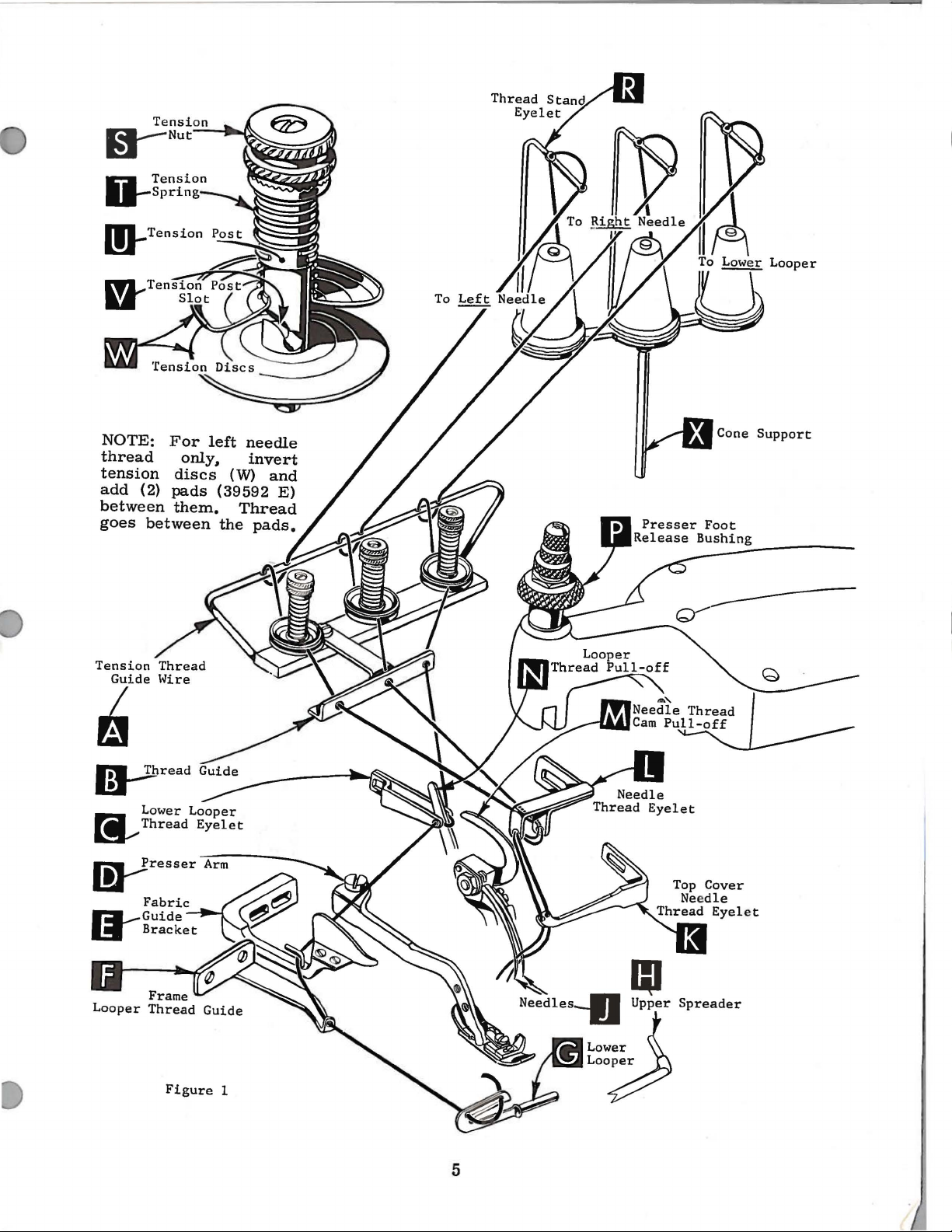
NOTE:
thread
tension
add
between
goes
Tension
Guide
For
only,
discs
(2)
pads
them.
between
~
~read
left
(W)
(39592
Thread
the
needle
invert
and
E)
pads.
Lower
~Thread
~resser
~Guide
1!1
Bracket
Fabric
Figure
Looper
Eyelet
Needles-IJ
1
I
5
IU
Upper
Low~r
La~
Spreader
{
Page 6
THREADING
(Continued)
Priortothreading.
to
bring
counterclockwise
out
of
CAUTION!
wire
tension
Double
(C)
from
Lead
guide
the
way
lower
Turn
position.
thread
cover
right
thread
needles
position.
(A,
Fig.
posts
right
thread
(F).
to
looper
handwheel
Insert
eyelet
needle
hole
eyelet.
(
end
through
Turnhandwheelin
the
can
(L).
thread
and
(J)
turn
Make
1).
are
U).
of
thread
to
left.
left;
be
both
under
the
Thread
swing
into
of
sure
between
and
Note:
eyelet
then,
threaded
in
operating
needle
neck
eyelet
left
needle
needles
cloth
high
the
the
TO
THREAD
lead
thread
on
top
operating
thread
easily
TO
threads
of
(K).
plate
position.
release
threads,
tension
it
through
of
fabric
through
THREAD
direction
from
top
cover
The
thread
from
open,
bushing
as
discs
LOWER
must
direction
if
tweezers
right
through
the
front.
turn
Release
(P).
they
pass
guard
both
right
casting
extend
(W)
both
in
eyes
NEEDLES
until
to
needle
handwheel
pressure
and
and
LOOPER
eyes
front
(E)
and
untilheel
from
are
in
needles
left,
and
then
thread
the
left
then
from
of
of
through
the
in
diagonal
lower
looper
through
oflower
left
left
hand.
(J)
down
should
hole
in
operating
on
swing
tension
looper
thread
eye
to
right.
are
BOTH
through
of
the
presser
presser
slots
thread
of
frame
looper
at
their
eyes
be
threaded
top
direction
foot
arm
thread
(V)
pull-off
(G)
Right
of
holes
cover
by
(D)
guide
of
the
eyelet
(N).
thread
is
all
eye
of
highest
needle
in
top
in
the
needle
a
The
amount
knurled
secure
should
increase
foot.
screw
tightening
the
been
presser
nut
inch
screw
On
approximately
that
differential
indicate
Unless
39
540-60
tension
proper
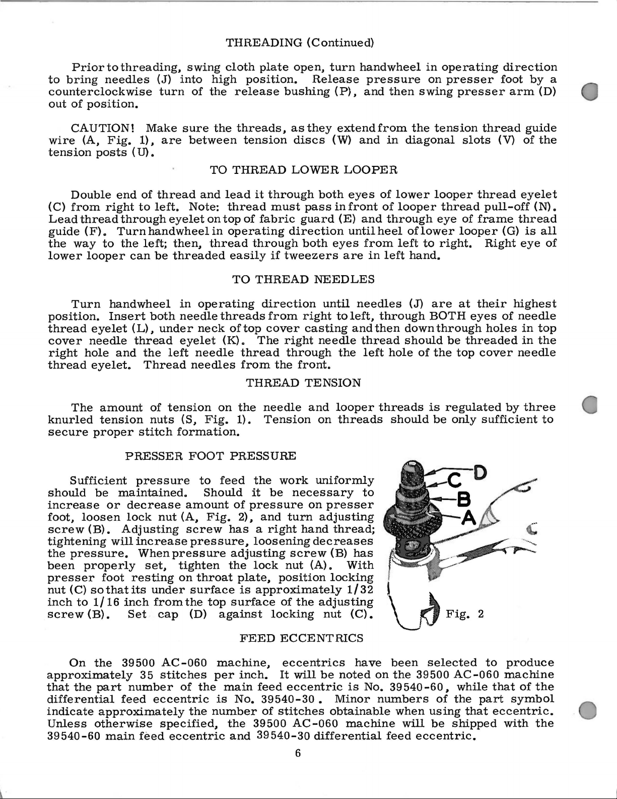
Sufficient
be
or
loosen
(B).
will
pressure.
properly
foot
(C)
sothatits
to
1/16
(B).
the
the
part
approximately
otherwise
main
maintained.
of
nuts
stitch
PRESSER
pressure
decrease
lock
Adjusting
inch
39500
feed
nut
increase
When
set.
resting
under
from
Set
cap
AC-060
35
stitches
number
eccentric
specified,
feed
tension
(S,
Fig.
formation.
FOOT
to
Should
amount
(A,
Fig.
screw
pressure,
pressure
tighten
on
throat
surface
the
top
(D)
of
the
the
eccentric
THREAD
on
the
1).
PRESSURE
feed
against
machine,
per
main
is
number
the
it
of
pressure
2).
has a right
loosening
adjusting
the
lock
plate.
is
surface
FEED
inch.
No.
the
39500
and
TENSION
needle
Tension
be
and
approximately
locking
feed
39540-30 • Minor
of
39
540-30
and
looper
on
threads
work
nut
position
of
ECCENTRICS
eccentrics
It
stitches
uniformly
necessary
on
presser
turn
eccentric
adjusting
hand
decreases
screw
(A).
the
adjusting
nut
will
be
AC-060
differential
obtainable
thread;
(B)
With
locking
1/32
(C).
noted
is
machine
to
has
have
on
No. 39
threads
should
~
~
f\J
been
the
39500
540-60 • while
numbers
when
will
feed
eccentric.
is
regulated
be
only
Fig.
selected
AC-060
of
the
using
be
that
shipped
by
sufficient
2
to
produce
machine
that
of
part
symbol
eccentric.
with
three
to
the
the
6
Page 7
FEED
ECCENTRICS
(Continued)
Generally
of
stitches
and
direction
Following
7.
a.
9,
60,
70,
eccentrics
number
Fig.
Atthis
lower
from
not
looper
center
have
produced.
10.
11.
100.
may
suffixed
3
point,
at
ofleft
lower
speaking,
of
stretch
stitch
12.
number
13.
Only
be
ordered
to
insert
the
left
needle,
looper
differential
Main
of
14,
two
eccentrics
indicate
Before
guard,
Then.
With
front
end
needle
lower
end
of
deflecting
(right
(left
hand)
material
feed
15.
being
eccentrics
16.
18.
are
separately.
number
ASSEMBLING
assembling
chip
guard.
follow
points
its
using
this
throat
of
needle
should
looper
stroke.
looper
plate
(A,
the
hand)
feed
eccentric
sewn.
are
20.
22.
supplied
To
of
stitches
AND
sewingparts.
upper
knife
suggested
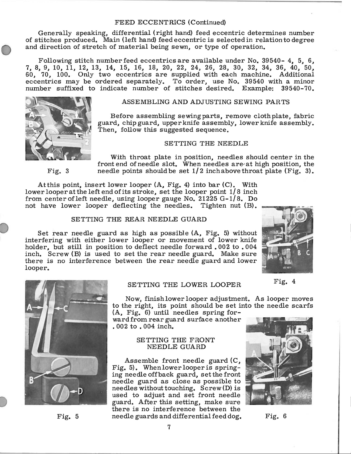
SETTING
in
position.
slot.
set
gauge
be
Fig.
the
When
set
4)
No.
needles.
feed
eccentric
is
selected
or
type
available
24.
26.
with
order.
use
desired.
ADJUSTING
assembly.
sequence.
THE
needles
needles
1/2
inchabovethroat
into
bar
looper
point
21225
Tighten
of
operation.
under
2a.
3o.
each
machine.
No.
Example:
SEWING
remove
lower
NEEDLE
are/ at
(C).
With
1/8
G-1/8.
nut
determines
in
relation
No.
39540-
32. 34.
39540
with a minor
PARTS
clothplate.
knife
should
high
plate
inch
Do
(B).
number
to
degree
4,
36,
4o.
Additional
39540-70.
assembly.
center
position.
(Fig.
5,
6,
5o.
fabric
in
the
the
3).
Set
rear
interfering
holder.
inch.
there
but
Screw
is
looper.
SETTING
needle
with
still
(B)
no
interference
Fig.
5
guard
either
in
position
is
used
THE
as
lower
to
between
to
(A.
ward
.
002
Fig.
ing
needle
needles
used
guard.
there
needle
REAR
high
looper
to
deflect
set
the
SETTING
Now,
the
finish
right.
Fig.
from
to • 004
SETTING
Assemble
5).
When
needle
guard
without
to
adjust
After
is
no
guards
NEEDLE
as
possible
or
movement
needle
rear
the
needle
rear
THE
lower
its
point
6)
until
rear
guard
inch.
NEEDLE
front
lower
off
back
as
touching.
and
this
interference
and
GUARD
(A.
forward
guard.
needle
guard
LOWER
looper
should
needles
surface
THE
FRONT
GUARD
needle
looper
guard,
close
set
as
Screw
set
front
setting.
between
differential
Fig.
of
5)
lower
• 00 2
Make
and
LOOPER
adjustment.
be
set
spring
for-
another
guard
is
spring-
the
front
possible
(D)
needle
make
sure
feed
without
knife
to • 004
sure
lower
into
(C,
to
is
the
dog.
As
the
Fig.
looper
needle
Fig.
4
moves
scarfs
6
7
Page 8
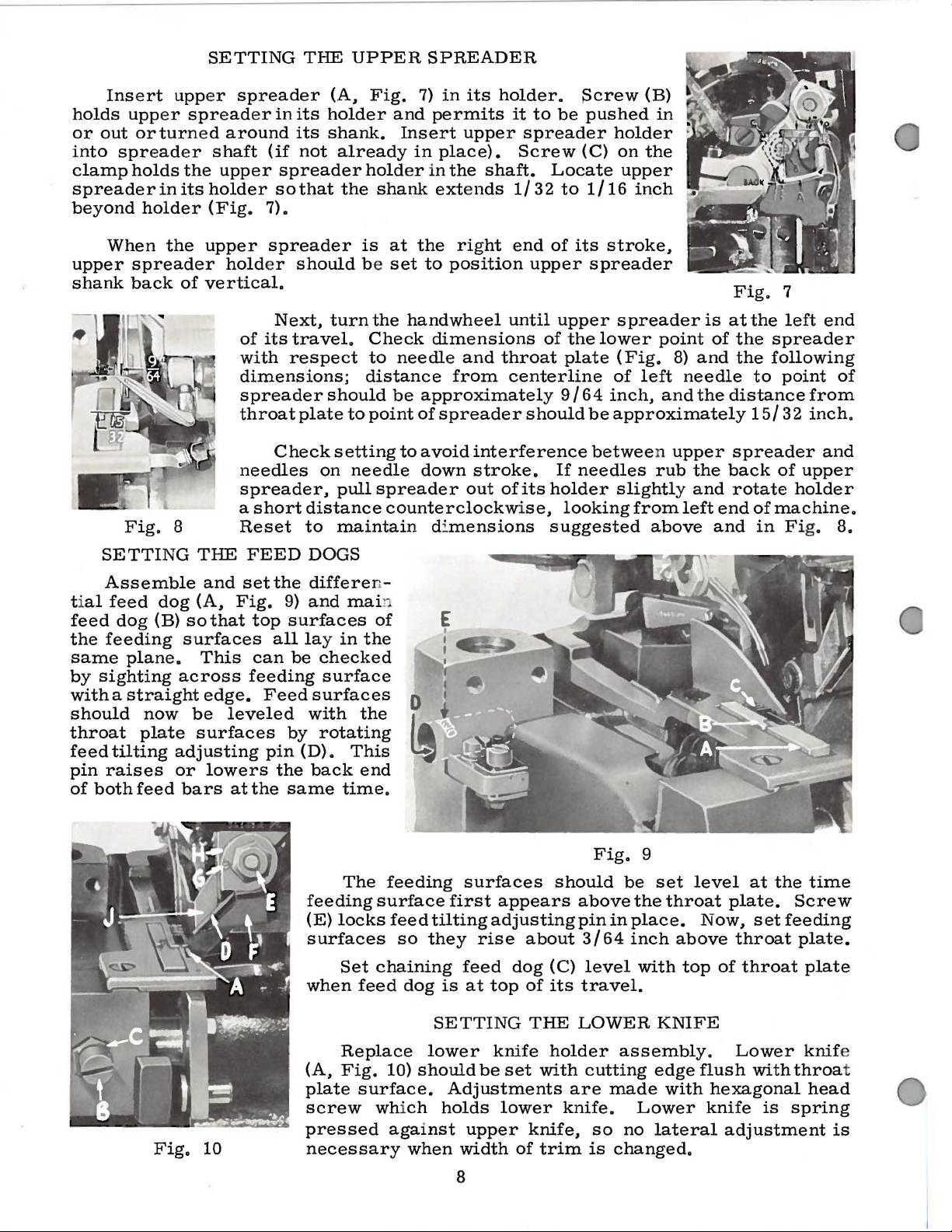
SETTING
THE
UPPER
SPREADER
Insert
holds
or
out
i
nto
clamp
spread
upp
orturn
holds
upp
er
er
er
spread
ed
shaft
the
upper
spreaderinitsholder
beyond
upper
shank
holder
When
spreader
back
Fig.
the
of
8
(Fig.
upper
vertical.
spreader
er
in
its
around
(if
its
not
spreader
sothat
7).
spreader
hold
er
should
Next,
of
its
travel.
with
respect
dimensions;
spreader
throat
plate
Check
needles
spreader,
a
short
Reset
(A,
holder
shank.
already
the
is
be
turn
should
to
setting
on
needle
pull
distance
to
maintain
Fig.
hold
the
Check
to
distance
point
7)
and
permits
Insert
in
er in
shank
at
set
extends
the
to
handwheel
dimensions
needle
be
approximately
of
to
avoid
down
spreader
in
its
upper
place).
the
shaft.
right
position
and
from
spreader
interference
stroke.
out
holder.
counterclockwise,
di
mensions
it
to
be
spreader
Screw
Locate
1/32
end
to
of
upper
until
upper
of
throat
plate
centerline
9/64
should
If
of
its
holder
looking
suggested
Screw
pushed
(B)
in
holder
(C)
on
the
upper
1/16
its
inch
stroke,
spreader
spreader
the
lower
point
(Fig.
of
left
inch,
be
approximately
and
between upper
needles
rub
slightly
from
above
is
8)
and
needle
the
the
and
left
Fig.
at
the
of
the
the
distance
15/32
spreader
back
rotate
end
and
7
left
spreader
following
to
point
of
upper
holder
of
machine.
in Fig.
end
of
from
inch.
and
8.
SETTING
Assemble
ti
al
feed
the
same
by
sighting
feed
feeding
dog
plane.
dog
(B)
across
with a straight
should
throat
feed
pin
of
both
now
plate
tilting
raises
feed
adjusting
or
THE
and
(A,
Fig.
so
that
surfaces
This
edge.
be
leveled
surfaces
lowers
bars
at
FEED
set
the
9)
top
surfaces
all
can
feeding
Feed
by
pin
the
the
same
DOGS
differe
and
lay
be
checked
surface
surfaces
with
rotating
(D).
back
feeding
(E)
surfaces
when
ma
in
the
the
This
end
time.
The
locks
Set
feed
n-
in
of
feeding
surface
feed
so
they
chaining
dog
surfaces
first
tilting
feed
is
at
appears
adjusting
rise
about
dog
top
of
should
above
pin
3/64
(C)
level
its
travel.
Fig.
in
9
be
set
the
place.
inch
with
level
throat
Now,
above
top
plate.
throat
of
throat
at
set
the
time
Screw
feeding
plate.
plate
Fig.
10
Replace
(A,
Fig.
plate
screw
surface.
which
pressed
necessary
SETTING
lower
10)
should
against
when
be
Adjustments
holds
upper
width
8
knife
set
lower
of
THE
holder
with
knife.
knife,
trim
LOWER
assembly.
cutting
are
made
so
no
is
changed.
KNIFE
edge
with
Lower
lateral
Lower
flush
with
hexagonal
knife
adjustment
is
knif
throa
head
spring
is
e
t
Page 9
SETTING
THE
LOWER
KNIFE
(Continued)
Lower
nut
(C)
cloth
not
plate
tightened
Replace
setting
At
bottom
1/64
inch
against
After
tightened
when
upper
knife
against
latch
upper
nut
(E)
of
below
the
upper
upper
to
lock
knife
may
support
spring,
against
to
hold
its
stroke,
cutting
knife
knife
upper
is
be
secured
bracket.
it
lower
knife
assembly.
clamp
front
edge
and
has
knife
replaced.
feed
actuates
eccentric
in
Because
should
knife
always
holder.
SETTING
(F)
in
cutting
oflower
slightly
been
set
h6lding
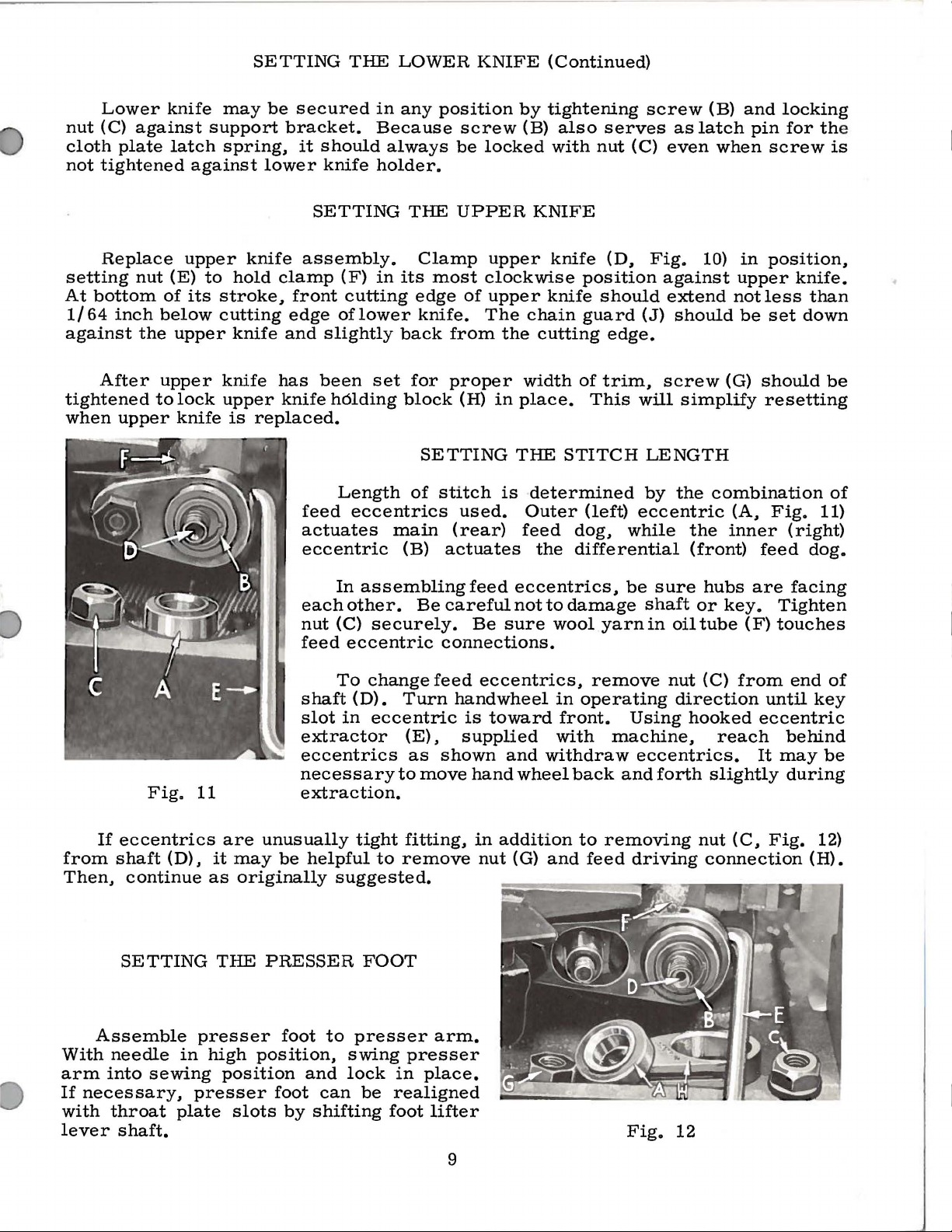
Length
eccentrics
any
position
THE
Clamp
its
most
edge
knife.
back
for
block
SETTING
of
stitch
main
(B)
screw
be
locked
UPPER
upper
clockwise
of
upper
The
from
the
proper
(H)
in
is
used.
(rear)
actuates
by
tightening
(B)
also
with
KNIFE
knife
position
knife
chain
guard
cutting
width
of
place.
THE
STITCH
determined
Outer
feed
the
(left)
dog,
differential
serves
nut
(D,
should
edge.
trim,
This
screw
as
(C)
even
Fig.
against
extend
(J)
should
screw
will
simplify
LENGTH
by
the
eccentric
while
(B)
and
latch
pin
when
10)
in
upper
notless
be
(G)
combination
(A,
the
inner
(front)
feed
locking
for the
screw
position,
knife.
than
set
down
should
resetting
Fig.
11)
(right)
dog.
is
be
of
If
from
shaft
Then,
Assemble
With
arm
If
with
needle
into
necessary,
throat
lever
Fig.
eccentrics
(D),
continue
SETTING
in
sewing
plate
shaft.
11
are
it
may
as
originally
THE
presser
high
position
presser
slots
each
nut
feed
shaft
slot
extractor
eccentrics
necessary
extraction.
unusually
be
helpful
PRESSER
foot
to
position,
and
foot
can
by
shifting
In
assembling
other.
(C)
securely.
eccentric
To
change
(D).
in
Turn
eccentric
(E),
as
to
tight
fitting,
to
remove
suggested.
FOOT
presser
swing
lock
in
be
realigned
presser
foot
feed
Be
careful
Be
connections.
feed
eccentrics,
hand
is
supplied
shown
move
hand
in
nut
arm.
place.
lifter
eccentrics,
not
sure
wheel
toward
and
wheel
addition
(G)
to
damage
wool
yarn
remove
in
operating
front.
with
machine,
withdraw
back
to
removing
and
feed
be
sure
shaft
in
oil
nut
direction
Using
eccentrics.
and
forth
driving
Fig.
12
hubs
or
tube
(C)
are
key.
(F)
from
hooked
reach
slightly
nut
(C,
connection
facing
Tighten
touches
end
until
key
eccentric
behind
It
may
during
Fig.
12)
(H).
of
be
9
Page 10
SETTING
THE
PHESSER
FOOT
(Continued)
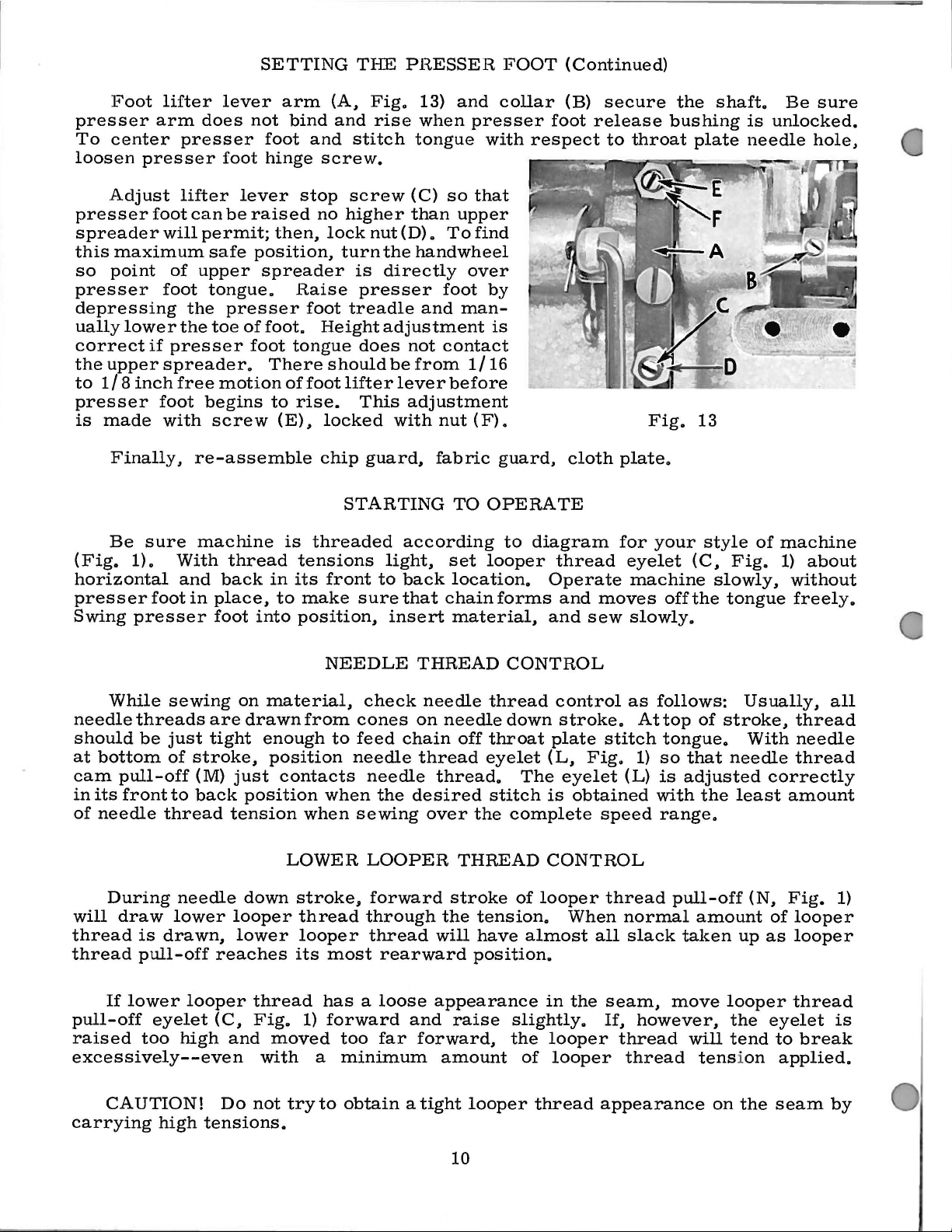
Foot
presser
To
center
loosen
presser
spreader
this
so
presser
depressing
ually
correct
the
to
presser
is
(Fig.
horizontal
presser
Swing
presser
Adjust
maximum
point
lower
if
upper
1/8
inch
made
Finally,
Be
sure
1).
presser
lifter
arm
foot
foot
does
presser
lifter
can
will
permit;
of
upper
foot
the
the
presser
spreader.
free
foot
begins
with
re-assemble
machine
With
and
in
lever
not
foot
lever
be
raised
safe
position,
spreader
tongue.
presser
toe
of
foot
motion
screw
thread
back
place,
foot
into
arm
bind
foot
hinge
stop
then,
H.aise
foot.
tongue
There
of
to
rise.
(E).
is
tensions
in
its
to
make
position,
(A.
and
and
stitch
screw.
screw
no
higher
lock
turn
is
presser
foot
treadle
Height
does
should
foot
lifter
This
locked
chip
STARTING
threaded
front
sure
Fig.
nut
guard,
13)
rise
when
tongue
(C)
than
(D).
the
hand
directly
and
adjustment
not
be
from
lever
adjustment
with
according
light,
to
back
that
insert
and
presser
with
so
that
upper
To
find
wheel
over
foot
man-
contact
1/16
before
nut
(F).
fabric
TO
set
looper
location.
chain
material,
collar
by
is
guard,
OPERATE
to
forms
(B)
foot
respect
cloth
diagram
thread
Operate
and
and
secure
release
to
plate.
for
eyelet
moves
sew
the
bushing
throat
Fig.
your
machine
offthe
slowly.
shaft.
plate
13
style
(C,
slowly,
is
unlocked.
needle
of
Fig.
tongue
Be
sure
hole,
machine
1)
about
without
freely.
While
needle
should
at
bottom
cam
pull-off
in
its
frontto
of
needle
During
will
draw
thread
thread
If
pull-off
raised
excessively--even
CAUTION!
carrying
sewing
threads
be
just
of
thread
lower
is
drawn,
pull-off
lower
eyelet
too
high
stroke,
(M)
back
needle
looper
high
tensions.
on
are
drawn
tight
just
position
tension
down
looper
lower
reaches
thread
(C,
Fig.
and
Do
not
material,
from
enough
position
contacts
when
LOWER
stroke,
thread
looper
its
1)
moved
with
try
a
to
NEEDLE
check
cones
to
feed
chain
needle
needle
when
most
has a loose
forward
the
desired
sewing
LOOPER
forward
through
thread
rearward
and
too
far
minimum
obtain a tight
THREAD
needle
on
needle
off
thread
thread.
over
will
appearance
forward,
eyelet
the
THREAD
stroke
the
tension.
have
position.
raise
amount
looper
CONTROL
thread
down
throat
stitch
control
plate
(L,
The
is
complete
CONTROL
of
looper
almost
in
slightly.
the
looper
of
looper
thread
stroke.
stitch
Fig.
eyelet
obtained
speed
thread
When
all
the
seam,
If,
appearance
as
follows:
Attop
tongue.
1)
so
(L)
is
with
range.
normal
slack
however,
thread
thread
of
stroke,
that
adjusted
the
pull-off
amount
taken
move
will
tension
on
Usually,
With
needle
correctly
least
(N,
of
up
as
looper
the
eyelet
tend
the
all
thread
needle
thread
amount
Fig.
looper
looper
thread
to
break
applied.
seam
by
1)
is
10
Page 11
If
butted
seam
the
purl
appearance.
results
when
POSITIONING
is
at
the
top
If,
however,
opened.
THE
edge
PURL
of
the
the
TO
garment.
purl
is
OBTAIN A FLAT
the
under
seam
the
can
edge. a less
SEAM
be
opened
into a near
flat
and
tighter
Raising
less
thread
and
causes
brought
thread
flexible
purl
as
The
being
sewn.
without
low
enough
and
to
be
the
too
far
breakage.
chain,
desired.
needle
thread
In
causing
to
prevent
bringing
pulled
purl
forward,
to
the
from
form
however,
looper
more
With a reasonable
the
looper
THREAD
thread
TENSIONS
tension
general.
the
lower
needle
threads
looper
thread
the
cones
on
the
pull-off
required
looper
to
thread
pull-off
as
the
the
top
of
thread
amount
eyelet
WITH
RESPECT
is a function
thread
be
tension
pulled
breakage.
eyelet
looper
the
edge.
becomes
of
looper
should
of
should
too
far
(C.
travels
If
too
thread
be
TO
needle
be
over
Fig.
to
the
the
eyelet
tight.
resulting
tension
adjusted
STITCH
thread
set
as
the
top
1)
forward
top
and
high
of
of
is
to
to
position
the
as
the
causes
its
stroke
raised
in
looper
insure
material
possible
seam
and
a
the
and
11
Page 12

12
Page 13

The
parts
parts
used
illustrated
on
Style
on
the
39500
preceding
AC-060,
page
but
not
and
used
described
on
Styles
on
this
39500
page
A,
represent
B,
P,
or
the
AF.
Parts
39500
Use
Ref.
No.
-
1
2
3
4
5
6
7
8
9
10
11
12
13
14
15
16
17
18
19
20
21
22
23
24
25
26
27
28
**-
*-
*-
shown
A,
B,
Catalog
39552
22596
154
39551
51292
51292
39592
39592
39556
39520
39530
22738
39530
22768
39597
22738
39530
39568
39505
39526
39505
39525
39525
39528
39508
39560
39578
39563
39522
39540
39540
39568
in
phantom
P,
No.
Part
No.
H
E
50-774
GDS
F
F-1
F-2
E
E
J
AC
R
G
B
AB
p
B
E
AC
AC
93 A
H
J
AC
B
A
BB
X
cc
B-30
B-60
R
and
AF
103 S for
Blk.
views,
and
bearing
39500
all
parts
Needle
Screw-----------------------------------Stop
Needle
Needle
Needle
Looper
Pad,
Pad,
inverted
PresserArm--------------------------------Presser
Chain
Screw -Chain
Hinge
Screw -Tongue
Presser
Screw -Chip
Presser
Looper
Chaining
Differential
Main
Screw -Main
Needle
Needle
Throat
Lower
Upper
Chip
Top
Crankshaft
Differential
Main
Frame
Guard-----------------------------------
Cover
no
reference
AC-060.
not
illustrated
Description
Driving
Pin----------------------------------
(size
Clamp
Thread
Thread
for
39592
for
left
tension
Foot---------------------------------
Thread
Feed
Feed
Guard,
Guard,
Plate,
Looper--------------------------------
Spreader-------------------------------
Feed
Looper
Arm,
029)-----------------------------Stud
Tension
Tension
F------------------------------
needle
Shield------------------------------
Spring
Foot
Foot
Eyele~-------------------------
Dog
Feed
Dog,
Needle
----------------------------------Feed
Driving
Dog--------------------------
marked
Feed
front--------------------------rear
marked
Driving
Thread
numbers,
or
marked
----------------------------
thread
discs------------------------
Shield
----------------------------and
Stitch
Guard
Chip
----------------------------
Dog------------------------
--------------------------"AY"
Thread
Eccentric-------------------
Guide
are
common
described
"A"---------------
Spring------------------
Spring------------------
only,
----------------------
Spring----------------Tongue,
-----------------------
Guard
"AM"------------------
------------------
--------------------
Eyelet----------------
Eccentric-------------
-------------------
here.
between
marked
to
"EK"---
Styles
Amt.
Req.
1
1
1
2
1
2
1
1
2
1
1
1
1
1
1
1
1
1
1
1
1
1
1
1
1
1
1
1
1
1
1
1
1
1
*
Not
shown
on
picture
plate,
but
used
on
13
this
machine.
Page 14

26
24
25
14
Page 15
THREAD
STAND
AND
MISCELLANEOUS
TOOLS
Ref.
N
o.
11
12
13
14
14A
15
16
17
18
19
20
21
22
23
24
25
26
27
28
29
Part
N
21113
21114
21114
21104
69 s
21130
22650
22650
21104
652 J -24
652
WA9A
651
21202
421
21227
21388
660-240
39599
116
o.
F
M
L
v
W-3
CB-4
CE-6
AA
J-16
A-16
D-34
BF
AU
A
Description
Thread
Fell
Spool
Cone
Thread
Washer
Washer
Lock
Nut---------------------------------------------Screwdriver--------------------------------------
Treadle
Cam
Socket
eccentrics
Thread
Threading
Wrench,
Stand
Eyelet
Eyelet----------------------------------------
Pads
Pin-----------------------------------------
Support
Screw -Thread
Screw-
Stand
------------------------------------------
------------------------------------------
Washer-------------------------------------
Chain
Extractor------------------------------------
Wrench,
Tweezers
Eyelet
Locking
----------------------------------------
-------------------------------------
Thread
Rod---------------------------------
------------------------------------
--------------------------------------
Wire-----------------------------------
for
9/32 inch
and
Support
Ring----------------------------
Sta
nd
Eyelet--------------------
Stand
for
3/8
---------------------------------
Rod----------------------
inch
nuts-------------------------
Rod----------------
nuts
holding
Amt.
Req.
3
6
6
3
3
1
3
1
1
1
1
1
1
1
1
1
feed
1
1
1
. 1
15
Page 16
.-o
..
..
'
<I
WORLD'S
,_,lf
FINEST
QUALITY
*
INDUSTRIAL
SEWING
MACHINES
UNION
SPECIAL
maintains sales
and
facilities throughout the world. These offices
aid
you
in
the selection of the right sewing
equipment for your particular operation. Union
and
Special representatives
tory trained
promptly
tion, there
and
is
serve you. Check with
ATLANTA,
BOSTON, MASS.
CHICAGO,
DALLAS,
LOS
NEW YORK, N.
PHILADELPHIA,
GA.
ILL.
TEXAS
ANGELES,
CAL.
PA.
and
are
efficiently. Whatever your loca-
a Union Special Representative
Y.
service men
able
to serve your needs
him
today.
MONTREAL,
BRUSSELS,
LEICESTER,
LONDON,
PARIS,
STUTTGART,
FRANCE
service
will
are
fac-
to
QUEBEC
BELGIUM
ENGLAND
ENGLAND
GERMANY
.
Representatives
Industrial
MACHINE
4 0 0 N • F R A N K L I N S-f'. I c H I c A G 0 I I L L • 6 0 6 1 0
and
cities
distributors
throughout
COMPANY
in
the
all
Important
world.
 Loading...