

Union Special 39500AB, 39500AC, 39500AE User Manual
•
•
®
STYLES
39500AB
39500AC
39500A
INDUSTRIAL
MACHINES
CLASS
CATALOG
No.
103AB
HIGH
STREAMLINED
SPEED
CHICAGO
39500
OVERSEAMERS

Catalog
(Supplement
INSTRUCTIONS
No.
to
Catalog
FOR
103
No.
AB
103 S)
ADJUSTING
39
500
The
furnished
AB
parts
at
LIST
CLASS
listed
list
First
AND
OF
Styles
39500
prices
OPERATING
PARTS
39500
AC
in
this
Edition
for
39500
catalog
repairs
AE
are
only.
Union
Rights
Copyright
by
Special
Reserved
1960
Machine
in
All
Countries
MACHINE COMPANY
INDUSTRIAL
Printed
SEWING
CHICAGO
in
MACHINES
U.S.A.
Co.

IDENTIFICATION
OF MACJITNE
Each
into
the
Union
name
Machines
contains
i
ndicatesthe
is
reserved
is
of
This
no
letters.
as a suffix
"Special"
catalog
standardStyleof
conjunction.
39500
parts
number,
A,
B,
are
Opposite
description,
P
shown
the
Adjusting
concerned
This
herein
Class
with
catalog
and
39500.
can
aretakenfromthe
direction
of
handwheel
Special
plat
similar
machine
e.
in
Example:
to
construction.
APPLICATION
is a supplement
Parts
or
illustrated
AF
machines.
in
phantom
illustration
and
and
operating
39500
applies
also
AB,
specifically
be
applied
References
operator'sposition
is
is
identified
construction
the
11
39 500
a
machine.
standard
to
in
this
For
to
help
page,
amount
parts
required.
instructions
AC
and
AE.
with
to
direction,
away
from
by a Style
are
grouped
11
•
Letters
Example:
Style
OF
CATALOG
Catalog
catalog
clarity,
locate
are
to
the
standard
discretion,
such
while
seated
operator.
number
by a Class
suffixed
"39500
identification
No.
103 S
represent
certain
39500
AB,
identified
included
Styles
to
some
as
right,
at
left,
the
which
to a Class
AB".
to
specify
and
should
parts
39500
A,
AC
by
detail
represent
of
machine
Special
front,
machine.
is
number,
I:..etter
be
not
B,
P
and
AE
number,
only
machines
back,
Operating
stamped
which
number
"Z"
machine
used
used
and
AF
parts.
part
areas
as
listed
etc.,
in
in
of
Two
Needle,
seaming
Pressed
39500
AB
Special
range
39500
AC
standard
inch;
39500
AE
Attachment.
approximately
70
per
CAUTION!
be
filled
A
straight
before
Fahrenheit
One
Machine.
Lower
For
closing
SSa-1;
20
to
For
seam
standard
For
closing
inch.
beginning
mineral
should
Looper,
Differential
Knife,
standard
100
per
closing
width
setting
Seam
3/32
Oil
was
oil
be
STYLES
One
Automatic
women's
seam
inch;
standard
men's
approximately
35
per
women's
specification,
inch.
Stitch
drained
to
operate.
of a Saybolt
used.
OF
Spreader,
Feed,
Lubricating
seamless
width
hosiery.
inch.
seamless
range
OILING
from
machine
Oil
viscosity
MACJITNES
Three
Trimming
System.
nylon
is
approximately
setting
80
Seam
1/8
inch.
hosiery.
Special
20
SSa-1;
to
when
capacity
Thread,
Mechanism
hosiery.
per
Seam
inch.
specification,
Stitch
range
Prepared
standard
100
per
inch;
shipped,
of
of
Class
200
to
39500
250
Low
Throw
with
specification,
3/32
inch.
Special
20
for
seam
standard
so
reservoir
is
seconds
Over-
Spring
Stitch
SSa-1;
to
100
per
Paramount
width
setting
must
six
ounces
at
100
is
6
Machine
at
sight
between
is
gauge
gauge
filled
on
front
lines.
with
of
oil
at
spring
machine.
Red
cap
bulb
in
top
on
cover.
oil
level
3
Oil
level
indicator
is
checked
should
show
OILING
(Continued)
Machine
keeping
oil
It
is a magnetic
may
denotes
size
main
as
required.
Drain
have
Each
the
number,
plug
entered
Union
measured
Collectively,
given
these
double
spotted,
on
39500
styles
slab,
the
AB,
chromium
is
automatically
reservoir
screw
screw
the
Special
kind
of
stamped
in
thousandths
type
label
is
AC
Type
of
and
standard
filled.
is
designed
crank
needle
shank,
on
and
size
all
AE
154
length,
plated
lubricated.
Check
located
case.
point,
the
at
to
accumulate
It
has
both
length,
needle
of
an
number
needles
packaged
use a curved
GCS.
It
curved
needle
No
oil
daily
back
should
of
machine
be
NEEDLES
type
and
groove,
shank,
inch,
denotes
midway
represent
and
blade
is a slabbed
blade,
in
sizes
025,
oiling
before
possible
removed
size
number.
finish
the
sold
needle.
shank,
double
027,
is
necessary,
the
morning
near
bottom
foreign
and
cleaned
and
largest
between
complete
by
Union
The
round
groove,
029,
032.
edge
materials
periodically.
The
Type
other
details.
diameter
shank
symbol
Special.
standard
point, • 046
struck
other
start.
of
number
of
and
which
needle
groove,
than
Add
base.
which
The
blade,
eye.
is
for
inch
To
have
a
sample
needle,
description
154
GCS,
Size
Selection
should
use
pass
freely
Success
of
needlespackagedunderourbrandname,
in
by a reputation
ship
for
more
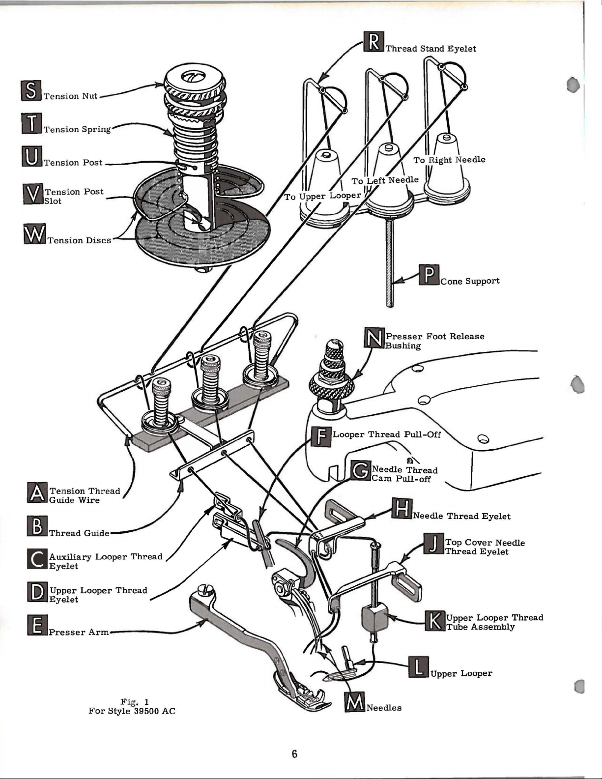
Release
(N,
Figs. 1 and
in
the
operating
Using
needle
high
hexagonal
clamp
position;
needle
on
label.
025".
of
proper
through
the
operation
for
producing
than
pressure
2),
direction
socket
nut
about
withdraw
orders
or
promptly
the
type
A
complete
needle
size
needle
of
highest
three-quarters
CHANGING
on
presser
and
swing
presser
until
wrench,
1/4
turn.
needles.
and
and
size
order
is
determined
eye
in
Union
Special
quality
of a century.
foot
needles
No.
21388
Again
accurately
number
would
order
needles
NEEDLES
by
turning
arm
(E)
are
AU,
turn
filled,
should
read:
by
size
of
to
produce a good
machines
~
can
in
materials
presser
out
ofposition.
at
their
lowest
furnished
handwheel
an
be
"1000
thread
be
foot
with
until
empty
package,
forwarded.
Needles,
used.
stitch
secured
which
artd
release
formation.
workman-
Thread
only
is
backed
bushing
Type
Turnhandwheel
point
machine,
of
travel.
loosen
needles are
Use
by
at
To
to
the
left,
needles
travel,
foot
bushing
replace
in
this
then
insert
position,
tighten
(
N).
needles,
needles
nut.
leave
in
holder
turn
Return
needle
holder
until
handwheel
presser
they
until
4
rest
arm
at
high
against
holder
(E)
position
is
to
position;
the
aga
in
and,
stop
at
re-lock
pin.
its
with
low
the
flats
Keeping
point
of
presser

THREAD
STAND
39500
is
eyelet
and
then
thread
39500
brought
(X)
Next,
guide
(Figs. 1 and
complete
needle,
are
position
foot
presser
AC
ONLY
After
brought
up
thread
up
(R,
Fig.
through
through
continued
guide
AB
After
through
thread
wire
Only
AND
thread
up
through
(A),
parts
(B) •
slot
is
2).
The
following
threading
and
conclude
given
Prior
below.
to
to
bring
threading,
by a counterclockwise
arm
(E)
comes
from
BACK
1).
Next,
left
hand
between
39500
hole
tension
AE
comes
the
BACK
(V),
and
extended
through
holes
involved
Parts
are
recommended
of
upper
by
complete
swing
needles
out
of
position.
thread
thread
thread
of
ONLY
from
down
down
in
presented
looper,
(M)
into
turn
cones
eyelet,
is
extended
the
tension
discs
cones
thread
(W),
(positioned
eyelet,
through
through
in
the
the
thread
THREADING
threading
in
procedure
progress
threading
cloth
high
of
plate
position.
the
(positioned
then
down
thread
through
then
FRONT
left
hand
guide
are
shown
their
relative
simplifies
to
for
left
open,
turn
Release
release
on
down
through
through
guide
slot
on
cone
continues
thread
hole
(B).
in
threading:
complete
needle.
handwheel
bushing
cone
support
FRONT
the
right
wire
(VL
(A) •
and
support
between
eyelet
in
the
tension
threading
positions
Beginning
threading
Steps
pressure
(
N),
and
hand
Thread
on
(P)},
(R,
diagrams
for
for
threading
in
operating
on
then
(P)),
thread
hole
through
it
felt
pads
Fig.
thread
clarity
with
of
right
presser
swing
it
is
is
2).
.
CAUTION!
guide
slots
wire
(V)
Turn
thread
through
Thread
looper
and
using
Pull
each
eye
thread
down
the
thread
machine.
from
CAUTION!
passing
Turn
position.
needle
holes
thread
in
threaded
top
cover
Make
(A,
Figs. 1 and
of
the
tension
handwheel
through
both
must
auxiliary
eyes
pass
tube
through
forked
out
bottom
Push
front
to
Be
from
tube
handwheelin
Insert
both
eyel
top
cover
in
the rig
needle thread
sure
posts
TO
until
of
upper
in
front
assembly
thread
end
of
oftube
tube
back.
sure
upperlooperthread
assembly
operating
needle
et
(H),
needle
ht
hole
eyelet.
thethreads,
2),
are
(U).
THREAD
point
looper
looper
of
thread
thread
as
between
UPPER
upper
they
looper
eyelet
eyelet
oflooperthreadpull-off
(K),
lead
the
thread
tube
under
thread
and
assembly
the
threading
using
down,
to
upper
TO
THREAD
threads
neck
the
hooked
and
then
looper
direction
from
of
top
eyelet
left
(J).
needle
Thread
(K).
wire,
NEEDLES
until nee
right
cover cas
needles from
extendfrom
tension
LOOPER
(D)
under
This
end
oftweezers,
insert
is
under
eye.
to left,
The rig
thre
ad
discs
(L)
is
(C)
from
from
(F).
neck
is
easily
supplied
thread
the
dles
( M) a r e
tin
g a
ht nee
throu
the front.
(W)
all
the
back
left
After
of
with
also
through
needle
throu
nd
dle
gh
the
the
tension
and
in
diagonal
way
left.
to
front,
to
right.
pulling
top
up
cover
accomplished
each
machine.
supplied
upper
threads
at
their
gh
BOTH
then
down
thread
left
throu
should
hole
thread
Lead
then
NOTE:
upper
casting
by
with
looper
when
highest
eyes
of
gh
be
of
the
The
knurled
sufficient
amount
tension
to
secure
of
tension
nuts
(S, Fi
proper
THREAD
on
the nee
gs. 1 and
stitch
TENSION
dle
and
looper threads
2).
Tension
formation.
5
on
threads
is
regulated
should
by
be
thr
only
ee
~~Te
m
U s
rlJ
ns
Tension
lot
Tension
i
on
Nut
Post
Discs
one
Support
n
Tension
fal
Guide Wire
r.:ii'I
Auxiliary
i!IJ
Eyel
l'i:t
Upper
~
Eyelet
et
Looper
Thread
Looper
For
Style
Thread
Thread
Fig. 1
39500
AC
6
r
Looper
Assembly
Thread
 Loading...