

Page 1
®
I
NDUSTRIAL
SE WI N G
OUAUT
•
ST
YLE
S
39
500
39
500
8
39500P
39500AF
Y
~
LEWIS
•
COLUMBIA
MACHINES
CATALOG
No.
10
35
SECOND
EDITION
H
IGH
CL
ASS
39500
STREAMLINED
SPEED
OVERSEAMERS
-
~
.
;,·
.
CHICA
G O
Page 2
Catalog
INSTRUCTIONS
No.
FOR
103
S
ADJUSTING
The
furnished
39500
39500
parts
at
LIST
CLASS
A
B
listed
list
Second
AND
OF
Styles
in
prices
Edition
OPERATING
PARTS
39500
39500
39
500
this
catalog
for
p
AF
repairs
are
only.
•
"__._
..
_
Union
Rights
MAC
Copyright
Special
Reserved
HINE
INDUSTRIAL
CHI CA
Printed
1957,
by
Machine
in
COMP
SEWING
in
2
1960
All
AN
MACHINES
GO
U.S. A.
Countries
Co
Y
.
March,
1964
Page 3
FOREWORD
The
streamlin
performance
Class 395
ed s
tyli
00
ng.
are characteristics
machine is
automatic
precision methods insuring
It
is
enable
Specials.
nd
illustrat
a
Union Sp
anxious
our consta
the
cus
The following
e a
ecia
to
cooper ate
nt
aim
tom
er
to
secure
nd describe the
l r epresentativ
with
complete
to
furnish
pages
you
to plan
lubr
of the
all
possible
contain
parts
es
will
Union
ica
int
ca
Special's
tion,
se
machines.
er change
refully
and light
prepared
advantage
valuable operating
for
Style
be found
and
s in
in all
estim ate r equir em
~
latest ove
ability.
s
Cla
ss
m anufa
redger.
running hi
All
part
s a
information
from the use
an
d a
djusti
39500
.
cturing
ents.
MACHI
gh
re
NEC
Ne
s peed
made
that
of
by
will
Union
ng data,
centers,
OMPA
NY
w
3
Engineerin
g Department ·
Page 4
IDENTIFICATION
OF
MACHINES
Each
plate
Standard
the
letter"
letter
is
suffixed
Styles
number,
This
herein.
Class
back,
Operating
Single
chine.
Knife,
39500
Union
on
the
Style
Z".
"Z" . When
to
of
which
catalog
lt
can
39500.
etc.,
direction
Curved
Differential
Automatic
A
For
fabrics
nation
slips,
seams
seam
main
has
pajamas,
are a primary
widths,
and
39500 B For
fabrics
nation
has
shirts,
Seam
stitch
specification,
range,
39500 P For
fabrics
underwear
seam
width,
differential
39500
AF
Same
seaming
rayon
and
widths,
and
differential
Special
machine.
numbers
Example:
only
the
standard
machines
contains
applies
also
All
references
are
taken
Blade
Lubricating
seaming
of
cotton,
been
3/32
differential
seaming
of
cotton,
been
panties,
8-30
seaming
made
and
from
similar
1/8
feeds.
as
all
types
silk
3/32
and
carries
Style
numbers
have
"Style
minor
Style
similar
no
letters.
APPLICATION
specifically
be
applied
from
of
the
handwheel
STYLES
Needle,
Feed,
silk,
Trimming
light
or
and
designed
nightgowns,
requisite.
and
1/8
feeds.
light
silk,
designed
infants'
and
or
for
and
504-SSa-1;
per
inch;
medium
cotton
garments.
inch;
39500
fabrics.
1/8
and
stitch
P,
weights
Seam
inch;
feeds.
a
Style
one
or
more
39500
changes
number.
in
construction
Example:
to
with
to
discretion
directions,
operator's
is
away
OF
Two
Looper,
System.
medium
similar
especially
or
similar
Seam
inch;
stitch
medium
similar
general
children's
standard
cam
to
heavy
and
wool,
Seam
range,
except
fitted
of
specification,
stitch
range,
number
are
classified
letters
A".
Special
are
made
Example:
OF
CATALOG
the
standard
such
position
from
MACIDNES
Three
Mechanism
weight
weight
for
use
synthetics.
articles
specification,
range,
weight
weight
synthetics.
purpose
knit
seam
adjusted
weight
used
specification,
8-20
per
with
flat,
warp
8-20
which
is
stamped
as sta
ndard
suffixed,
Style
numbers
in a standard
are
"Class
Styles
to
some
as
while
"Style
grouped
right
39500
39500".
of
machines
special
and
seat
ed
operator.
Thread,
with
flat,
Overseaming
Spring Pressed
warp, and
The
on
women's
where
long
504-SSa-1;
8-30
flat,
per
warp,
inch;
The
seaming
wear,
widths,
main
flat,
on
snow
of
and
and
differential
warp,
suits,
similar
3/32
504-SSa-1,
inch;
cam
adjusted
39500 B sewing
and
ribbed
504-SSa-1;
per
inch;
cam
and
but
never
machine,
under
m'}ChineS
left,·
at
the
sewing
and
straight
cam
and
sewing
"T''
shirts,
and
and
sweat
parts.
knit
cotton,
standard
adjusted
in
the
special.
contain
contain
a
AZ".
a
Class
as
listed
front
machine.
Lower
ribbed
combi-
children's
hanging
standard
adjusted
ribbed
combi-
garments.
1/8
feeds.
ribbed
shirts,
standard
main
seam
name
the
11 Z 11
in
and
Ma-
knit
knit
polo
inch;
knit
and
For
wool
main
OILING
CAUTION!
must
be
ounges.
100
Fahrenheit
Ma
at
sight
between
filled
A
chine
gauge
gauge
Oil
before
straight
should
is
filled
on
front
lines.
was
drained
beginning
mineral
be
with
of
machine.
oil
used.
oil
from
to
operate.
of a Saybolt
at
spring
Red
4
machine
Oil
viscosity
cap
in
bulb
on
capacity
top
oil
when
cover.
level
shipped,
of
of
200
Oil
indicator
Class
to
250
level
so
reserv.o
39500
seconds
is
should
1r
is
six
at
checked
show
Page 5
OILING
(Continued)
Machine
keeping
oil
as
main
required.
Drain
It
is a magnetic
may
have
cally.
Each
denotes
size
Union
the
number,
measured
tively,
the
label
type
of
39500
standard
length,
needle
single groove,
chromium
is
automatically
reservoir
plug
screw
screw
entered
Special
kind
stamped
in
thousandths
and
size
all
needles
A,
39500
for
plated
the
of
these
in
filled.
is
located
designed
crank
needle
shank,
on
point,
the
of
number
packaged
B,
39500 P and
styles
shallow
sizes
022,
lubricated.
Check
at
back
to
accumulate
case.
It
NEEDLES
has
both
length,
needle
an
inch,
shank,
representthe
and
39500
is
Type
spot,
025,
027, 029,
No
oil
daily
of
machine
should
type
and size
groove,
midway
complete
sold
by
AF
154GAS.
long
oiling
is
before
near
possible
be
removed
number.
finish
denotes
largest
between
symbol
Union
Special.
use a curved
It
is a curved
tapered
032,
036,
necessary,
the
morning
bottom
foreign
and
and
other
diameter
shank
and
blade
point,
040,
edge
materials
cleaned
Th
e t
details.
eye.
which
needle.
blade,
struck
044.
other
start;
of
periodi-
ype
number
of
Collec-
is
given
standard
groove,
than
add
base.
which
The
blade,
on
The
To
have
a
sample
scription
Size
036".
needle,
on
Selection
should
pass
tion.
Success
use
of
needles
by a reputation
manship
for
Release
(U,
ating
socket
about
·
draw
Fig.
1)
and
direction
wrench
1/4
turn.
needle.
needle
label.
of
freely
in
the
orders
or
A
proper
through
operation
the
complete
packaged
for
producing
more
than
pressure
swing presser
until
No.
needle
21388
Again
type
needle
under
three
on
presser
AS,
turn
promptly
and
size
order
size
is
determined
needle
of
eye
Union
our
brand
highest
-quarters
CHANGING
foot
arm
(H)
is
at
its
furnished
handwheel
and
accurately
number
would
Special
in
read:
order
machines
name,
quality
of a century.
NEEDLES
by
turning
out
of
position.
lowest
with
until
point
machine,
needle
filled,
should
"1000
by
to
produce a good
size
be
forwarded.
Needles,
of
thread
can
~
needles
presser
in
materials
foot
Turn
of
travel.
loosen
is
at
high
an
empty
Type
used.
stitch
be
secured
which
release
handwheel
Using
needle
position;
package,
Use
de-
154GAS,
Thread
forma-
only
by
is
backed
and
work-
bushin
in
operhexagonal
clamp
nut
with-
g
To
to
the
needle
travel;
foot
release
replace
left,
in
this
then tig
needle,
insert
position,
hten
bushing
leave
needle
turn
nut.
(U).
needle
in
holder
handwheel
Return
holder
until
presser
it
until
arm
at
high
rests
holder
(H)
against
is
to
5
position
again
position;
and,
stop
at
re-lock
its
with
pin.
low
the
flat
Keeping
point
of
presser
Page 6
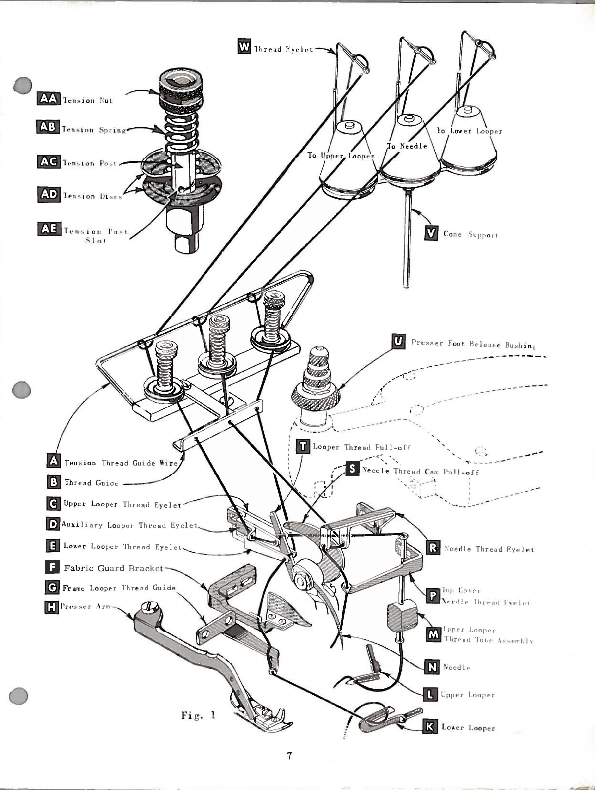
THREAD
STAND
Afterthread
throu
is
right
gh
back
thread eyele
threaded thr ough
hand
hol
tension dis cs
Only parts i n
Pa
rt s are
It
threading low
placed
will simplify
er
Before beg
at
ing dir e c
foot
by
of
positio
tion
turning presser
n .
Be sure threads,
tension
dis
cs (AD)
Double end
eye
let (E, Fig.
thread
of
heel
pull-o
frame
of
looper
lower
ff
looper
from left to r ig
are in
left
hand.
com
es from
each
e a
nd
up
(AD),
volved
in
their
threading thi
looper firs
inning
unt
il
needle
to
as
and
of
thread
1)
from rig
(T). Lead
thread gui
(K)
ht.
Left
cone on thread s
throu
throu
t, then
pair
gh slot
of
gh l e
down throu
hol
es
in
ft hand
hol
(AE),
THREADI
in
thread
relative pos
ing are shown
ition
s m a chine to
t,
upper
thread,
loop
er second,
swing cloth pla
(N) i s at high position, re
foot
r el
ease bu
t hey
in
TO
come
diagonal
THREAD
and
lead
ht
to
left. Note:th
thread behind
de
(G).
is
all
the
eye
of
low
s hing (U); a
from
slots
LOWER
it
throu
fabric guard
Turn
way
er
handwheel
to the
loop
the
(AE)
e r
tand
(V,
Fig.
1),
it
is
gh
front thre
ten
sion thread guide
ad
eyelet (W) .
wire (A),
e . Then thread continues
and on
throu
gh
thread
NG
in
thr
eading diagr am (Fig. 1).
s f
or clarity
follow
.
recommend
ed seq
and needle third.
te open
tension
in
, t
lea
nd swi
thread guid
tens
ion
urn handwheel
se pressure
ng p
resser
e, a r e betwe
posts (AC).
LOOPER
gh
both eyes o f
r ea d
must
(F) and
in ope
left; th
can
be
en thr e
thread
low
er
looper
pass
in front of
throu
gh
rating direction
ad
throu
ed eas
ily
brought
Next it
down
between
guide
(B).
uence
in ope
on presser
arm
(H)
thread
looper
both
hole
unt
gh
both eye s
if
tweezers
up
of
r-
out
en
s
il
Turn
thre
ad
throu
through
bo
threadmu
loop
er
thread
and
down throu
ush
tube down, then
p
CAUTIO
pass ing
fr
T ur n ha
highest pos
eedle
n
hol
knurl
to secu
thread eyele
e in
top cov
T
he amou
ed tens
re
handwheel
gh
auxiliary
t h e
yes
of
s t pass
N !
om
ndw
tube
gh
Be
tube
heel
in
front
assembly
thread
sure
assembly
in oper
ition. Inser
t (R) ,
er needle thread
nt
of tensi
ion
nut
s (AA, Fig.
prop
er s
titch
TO
THREAD
until
point
loop
upper loop
of
loop
e r
UPPER
of
upper loop
thread
er
thread
er
thread
(M), lead thread
tube
as s em b
insert
thread
throu
upperlooperthr
to
upper loop
TO
THREAD
ati
ng dir
ecti
t needle thread from
under neck of
eyelet
THRE
on
on needle and
form
ation.
AD
1).
Tension on
LOOPER
er
(L)
is
all the way le
eye
let (D)
eye
let
pull-off
(C)
(T).
from
from
under neck
ly
(M). Pull
gh
upp
ea
d is
er ey
THE NE
on unt
r ig
top
cover cas
(P).
Thread
er
E D
il needle
thread
looper
ey
underlowerlooper
e.
LE
ht
to
left,
tin
ne
edle from
TENSION
looper threads is reg
threads
back
left
Aft
er
of top cov
out bottom
e f
rom front
(N, Fig
throu
g; th
en
should
ft. Lea
to
fron
to right .
pulling up
er cas
of
to
th
r e
adwh
.
1)
is
gh
both eye s of
down
throu
front.
ulated
be
by
only
d
t, then
Not
e:
upp
e r
tin
g
tub
e;
bac
k.
en
at
its
gh
thr
ee
enou
gh
6
Page 7
~T
e nsion
Nul
rJiT,·nqon
IJ:I
T.,.,, ,
:;; )
Ten.,io
1!1
Thr e a d Gu 1
B U
pp
e r Loope
Posl
on
o!
n Th read
oe
r Thread E)·ele t
--
-
---
Pu
--
ll-
--
a
Thread
Presser Fool
---
....
,..
...
~
r·
"
"'-
Cam Pu
_..;
\
....
....
'
, _
ff
" ,-··
R~lea~~
-------------
--
Bushinl
----
-
--
,.
...
...
ll-off
...
...
____
---
..
,
--
--
-
......
--
-
I!JAuxil
D Loll
IJ F
B
iary
f'
r Looper T
abr
ic Guard Bracke
Fra
me
Lo opPr
Looper Th
hrea
read Eye
d Ey
elet
t
l e
Fi g. 1
7
~ eedle
Lp
pPr
Thread Fyel
l.oo
pn
~
_.,.
J,. \
et
___
.....
Page 8
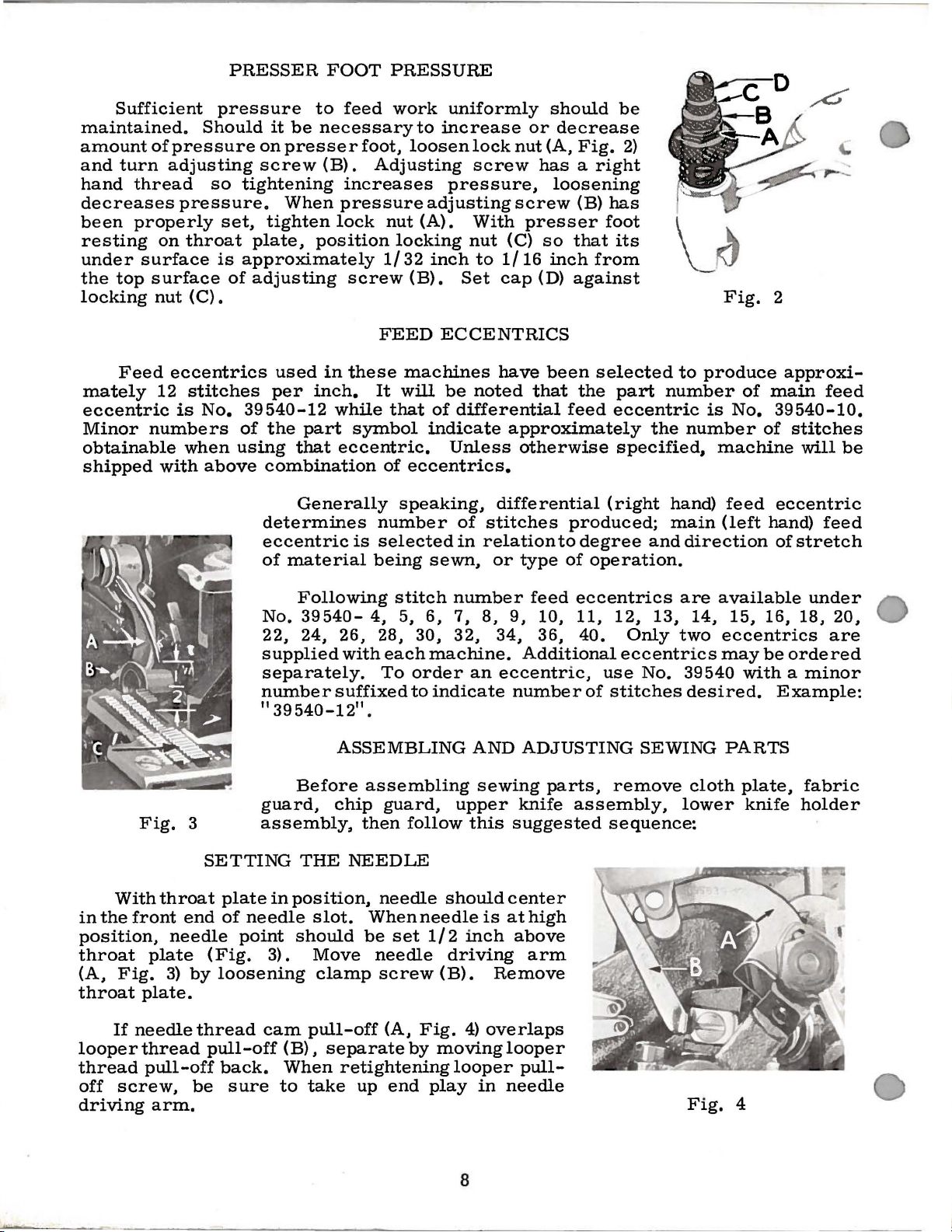
PRESSER
FOOT
PRESSURE
Sufficient
maintained.
amount
and
hand
of
turn
thread
decreases
been
resting
under
the
locking
properly
on
surface
top
surface
nut
Feed
mately
12
eccentric
Minor
numbers
obtainable
shipped
with
pressure
Should
pressure
adjusting
so
pressure.
set,
throat
is
of
(C) •
eccentrics
stitches
is
No.
when
using
above
to
feed
it
be
necessary
on
presser
screw
(B).
tightening
When
tighten
plate,
pressure
lock
position
approximately
adjusting
used
per
39540-12
of
the
inch.
part
that
in
while
eccentric.
combination
Generally
determines
eccentric
of
material
work
foot,
loosen
Adjusting
increases
nut
locking
1/32
screw
(B).
FEED
these
machines
It
will
that
symbol
of
eccentrics.
speaking,
number
is
selected
being
uniformly
to
increase
lock
screw
pressure,
adjusting
(A).
With
nut
inch
to
1/16
Set
cap
ECCENTRICS
have
be
noted
of
differential
indicate
Unless
differential
of
stitches
in
relation
sewn,
or
should
or
decrease
nut
(A,
Fig.
has a right
loosening
screw
presser
(C)
so
inch
(D)
been
that
(B)
has
foot
that
from
against
selected
the
feed
eccentric
approximately
otherwise
(right
produced;
to
degree
type
of
operation.
be
2)
its
to
part
number
the
specified,
hand)
main
and
Fig.
produce
of
is
No.
number
machine
feed
(left
direction
2
approxi-
main
feed
39540-10.
of
stitches
will
eccentric
hand)
of
feed
stretch
be
Fig.
With
in
the
front
position,
throat
(A,
Fig.
throat
If
needle
looper
thread
off
screw,
driving
3
throat
end
needle
plate
3)
by
plate.
thread
pull-off
arm.
SETTING
plate
of
needle
point
(Fig.
loosening
thread
pull-off
back.
be
sure
Following
No.
3954022, 24, 26,
supplied
with
separately.
number
11
39540-12
suffixed
ASSEMBLING
Before
guard,
chip
assembly,
THE
in
position,
NEEDLE
slot.
should
3).
Move
clamp
cam
pull-off
(B).
separate
When
to
retightening
take
stitch
4,
5,
6,
28,
30,
each
machine.
To
order
11
to
•
assembling
guard,
then
follow
needle
Whenneedle
be
set
1/2
needle
screw
(A,
Fig.
by
up
end
play
number
7,
8,
32,
an
indicate
AND
sewing
upper
this
should
is
inch
driving
(B).
4)
overlaps
moving
looper
in
feed
9,
10,
34,
36,
Additional
eccentric,
number
ADJUSTING
parts,
knife
suggested
center
at
high
above
arm
Remove
looper
pull-
needle
eccentrics
11,
12,
40.
Only
eccentrics
use
No.
of
stitches
SEWING
remove
assembly,
sequence:
13,
are
available
14,
two
eccentrics
may
39540
desired.
PARTS
cloth
lower
Fig.
under
15,
16,
18,
be
ordered
with a minor
Example:
plate,
knife
fabric
holder
4
20,
are
8
Page 9
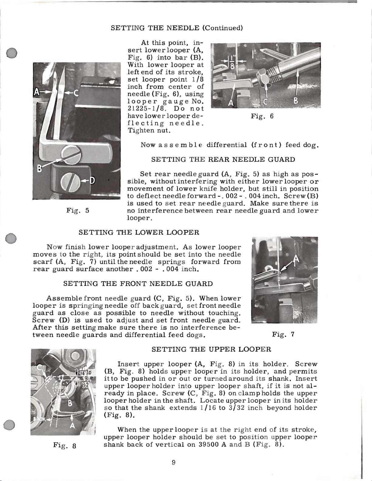
SETTING
THE
NEEDLE
(Continued)
Fi
g. 5
At this
se
rt
low
ig
. 6) i
F
W
ith
low
left e
nd
loop
s et
inch from
needl
l
21225-1/8.
ha
fl
Tighten nut
si
movement
to deflect needle
is used
no interference betw
looper.
e (Fig. 6), using
oo
per
ve
low
e c
tin
N
ow
Set r ea r need
bl
e,
without
poin
t, i
er l
ooper
nto
er
loop
of its s t r oke,
e r
po
center
g a u
Do
e r l
oop
g
needl
.
as
s e m b 1 e differential (fro n
SE
TT
ING
of
to
s et
(A,
bar (B).
er
int 1
ge No.
no
er de -
THE
le gua
int
erfe
low
er
for ward-. 002-
rear
n-
at
/8
of
t
e .
REAR
rd
r ing w
knife
n edle guard.
een rear needle
NEEDLE
(A, F ig . 5)
ith eith
hold
er,
Fi
g . 6
t) feed do
GUARD
as
high
er low
but still
. 00 4 inc
Mak
er loop
in positi
h. Scre
e s u
re ther e i s
guard and lower
as
g .
pos -
er
or
on
w (B)
Now fini
mov
es
scar
f (A, Fig. 7)
ear guard
r
Assembl
loop
e r
uard
g
Screw
After
tween
as
this
needl
SETTING
s h
low
to
the rig
SETTI
is spr inging needle o
clo
(D)
is used
setting mak
ht, its
surface
NG
e f
ront
se
as pos
e g
uards and dif
THE
e r
looper adjustm
point should
until
the
another . 002
THE
FRONT
needle g
sible
to adj us t
e s
ure
Insert upper looper
(B, Fi
it
upper
r e
looper holder in the s h
s o th
(Fig.
to
ady
g.
be
loop
in
at
8).
LOWER
need
le s pr in
NEEDLE
uard
ff
ferential
push
the s h
(C, Fig. 5).
back guard,
to needle
and set
ther
e is
SETTING
8)
holds upp r loop
ed in
er holder
place
ank
LOOPER
ent . As
be se t into the
- .
004
front
no
fe
ed dogs
or
. S
cre
extends 1/16 to
low
gs
forward
inc
h.
GUARD
set
without
needle gua
interfere
THE
(A, Fig. 8) in it s
out o r t ur n
into upper loop
w (
C,
aft.
er
loop
er
needle
fro
m
When
front needle
Fig. 8) on
L ocate upp
touch
nce
.
UPPER
er
low
e r
ing.
r d .
be-
in its h
ed aro
er shaft,
3/ 32 inch beyo
LOOP
und
clam
er loop
E R
old
er , a
its
p holds the up
er
Fi
g. 7
hold
er . Sc
nd permits
shank. Ins
if
it
is not a
in i
ts holder
nd holder
rew
ert
l-
per
Wh
Fi
g . 8
en the upper loop
upper loop
ha
nk
s
back of vertical
er holder shoul
9
er is
d be s
on 395
at the right en
00
d of its str oke ,
et
to position upper
A a nd B (F
ig.
8).
loop
er
Page 10

SETTING
THE
UPPER
LOOPER
(Continued)
NOTE:
holder
about
clearance
looper
the
lower
0.
**
looper
002
to
vertically.
holder
looper
*
On
should
between
around
o.
004
Fig.
Styles
be
in
or
its
to
clearance
10
39500 P and
set
to
position
Be
sure,
heel
of
out
of
upper
shank,
the
left
looper
check
point
throat
is
(A,
setting
*1/2
increased
wise
inch
of
may
slightly
the
on
all
looper
(Fig.
Next,
necessary,
NOTE:
is
upperlooper
and
looper
set
upper
of
the
lower
9).
turn
is
at
the
dimensions
with
plate
Fig.
and
looking
be
respect
(Fig.
10).
for
Styles
ForStyles
;~:*9/64.
by
increased
necessary
to
maintain
AF,
the
upper
styles,
casting.
shaft
looper
looper
handwheel
left
end
of
10).
do
it
Figure
39500 A and
Forexample,
turning
from
left
by
shaft.
to
upper
looper
By
and
point
of
upper
to
by
39500 P andAF,
upper
pulling
Afterthese
turn
the
looper
shank
there
adjusting
by
turning
to
cross
eye
until
its
travel;
looper
needle
If
resetting
moving
10
represents
looper
end
of
upper
upper
condition
is
with
and
the
B.
machine;
a
upper
the
thesettings
dimension
holder
dimension
looper
changes
looper
shown
around
in
Fig.
looper
counterclock-
holder
9
holder
dimensional
31/64inchis
left,
are
made,
its
shank
Fig.
9.
are
5/32
out
it
When
quickly
when
needle
looper
upper
looper
back
and
looking
dimensions
as
upper
eye
(Fig.
NOTE:
looper
Check
and
of
upper
rotate
from
the
correct
follows:
looper
should
11)
For
and
setting
needle
looper,
looper
of
Figs.
for
Styles
needle
on
left
setting
As
eye
be
about
Styles
to
needle
a
end
9,
Fig.
upper
centers
level
39500 P
should
avoid
downstroke.
pull
looper
short
of
10, 11.
12
is
obtained,
looper
on
39500 A and
interference
distance
machine.
the
with
and
align
out
is
needle,
top
AF,
exactly.
of
10
it
can
be
checked
moving
surface
B.
If
its
counterclockwise,
Reset
to
the
bottom
of
upper
the
eyes
between
needle
holder
to
three
so
in
checked
with a straight
should
plate
tilting
raises
both
of
upper
rubs
slightly
maintain
SETTING
On
feed
the
top
the
feed
right,
of
Style
same
now
surface
adjusting
or
the
the
the
THE
39500
dogs
surfaces
plane.
by
sighting
be
leveled
lowers
bars
FEED
(A,
of
edge.
by
pin
the
atthe
Fig.
11
A,
B, C,
teeth
This
across
Feed
with
rotating
(D).
back
same
DOGS
set
Fig.
all
can
teeth
dogs
throat
feed
This
end
time.
all
12)
lay
be
pin
of
Page 11
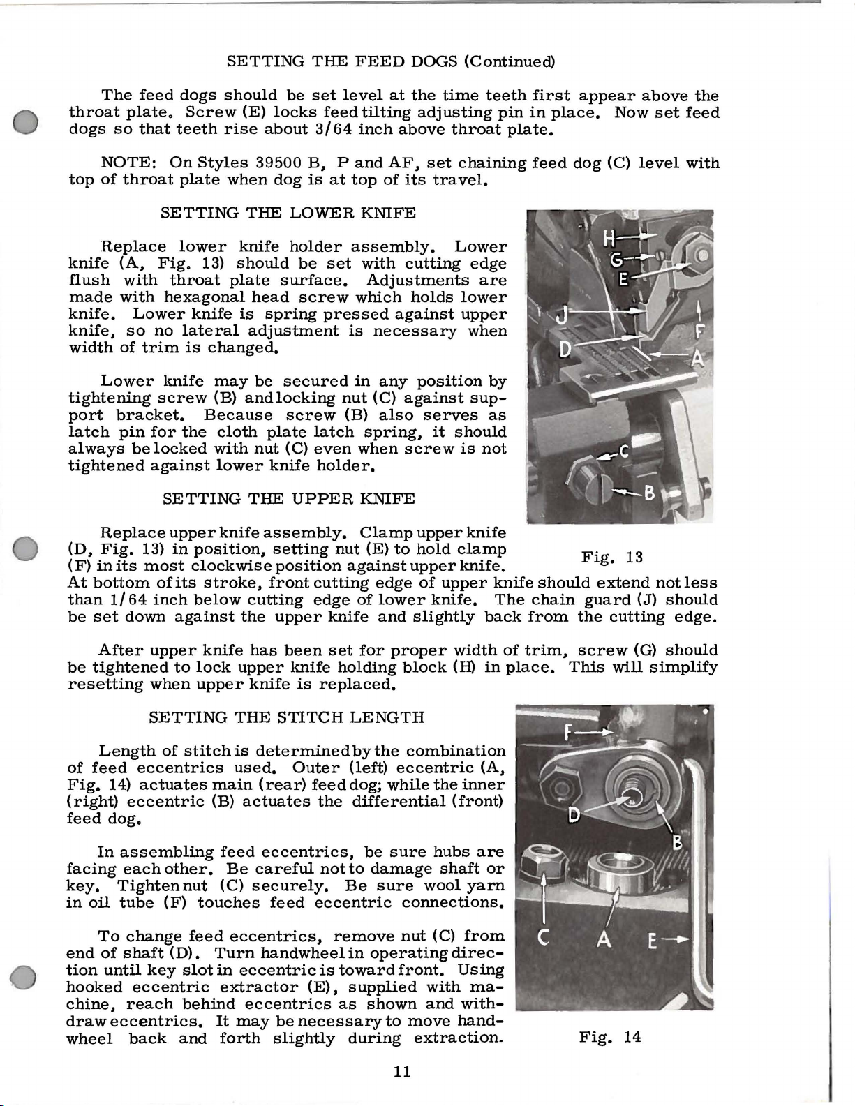
The
throat
dogs
plate.
so
feed
that
dogs
Screw
teeth
SETTING
should
(E)
rise
be
locks
about
THE
set
feed
3/64
FEED
level
tilting
inch
DOGS
at
the
adjusting
above
(Continued)
time
teeth
pin
throat
first
in
plate.
appear
place.
above
Now
set
the
feed
NOTE:
top
of
throat
Replace
knife
flush
made
knife.
knife#
width
(A#
with
with
Lower
so
of
Lower
tightening
port
latch
always
bracket.
pin
belocked
tightened
Replace
(D #
Fig.
(F)
in
its
At
bottom
than
be
set
1/64
down
On
plate
SETTING
lower
Fig.
throat
hexagonal
no
lateral
trim
is
knife
screw
for
the
against
SETTING
upper
13)
in
most
of
its
clockwise
inch
against
Styles
when
THE
knife
13)
should
plate
knife
is
adjustment
changed.
may
(B)
andlocking
Because
cloth
with
lower
THE
knife
position#
stroke#
below
cutting
the
39500
dog
LOWER
holder
be
surface.
head
screw
spring
be
secured
screw
plate
nut
(C)
knife
UPPER
assembly.
setting
position
front
upper
B# P and
is
at
top
KNIFE
assembly.
set
with
Adjustments
which
pressed
is
necessary
in
nut
(C)
(B)
latch
even
spring#
when
holder.
KNIFE
Clamp
nut
(E)
against
cutting
edge
of
knife
AF#
of
its
cutting
against
any
against
also
screw
to
edge
lower
and
set
travel.
Lower
holds
position
serves
it
should
upper
hold
upper
of
upper
knife.
slightly
chaining
edge
are
lower
upper
when
by
sup-
as
is
not
knife
clamp
knife.
knife
The
back
feed
should
chain
from
dog
Fig.
guard
the
(C)
level
13
extend
(J)
cutting
with
not
less
should
edge.
After
be
tightened
resetting
Length
of
feed
Fig.
14)
(right)
feed
dog.
In
facing
key.
in
Tightennut
oil
tube
To
end
of
tion
until
hooked
chine#
draw
eccentrics.
wheel
upper
to
lock
when
SETTING
of
stitchis
eccentrics
actuates
eccentric
assembling
each
other.
(F)
change
shaft
key
feed
(D).
slot
eccentric
reach
back
behind
and
knife
upper
upper
THE
used.
main
(B)
actuates
feed
Be
(C)
touches
eccentrics#
Turn
in
eccentric
extractor
eccentrics
It
may
forth
has
been
knife
STITCH
knife
is
replaced.
set
holding
LENGTH
determinedbythe
Outer
(rear)
feed
the
(left)
dog;
differential
eccentrics#
careful
securely.
feed
not
to
Be
eccentric
remove
handwheel
is
(E)#
in
toward
supplied
as
be
necessary
slightly
during
for
proper
block
combination
eccentric
while
be
sure
damage
sure
connections.
nut
operating
front.
shown
to
move
width
(H)
in
(A#
the
inner
(front)
hubs
wool
(C)
shaft
yarn
from
are
or
direc-
Using
with
and
ma-
with-
hand-
extraction.
of
trim#
place.
screw
This
Fig.
(G)
will
14
should
simplify
11
Page 12

SETTING
Fig. 15
THE
STITCH
LENGTH
If
(Conti
eccentri
nue d)
cs a
fitting. in addition
Fig. 15) from s
ful
to
remove
connec
n
all
a r m .
press
lo
foo
s
lots by shiftin
tion
y s ug
SE
A
ges
TTI
ss
emble press
With needle in high posi
er arm into sewi ng position
ck
in
plac
t c
an
be r e
haft
nut (G) a
(H) . Then c
ted.
NG
THE
e .
If
ali
gne
g f
re
unusua
to remov
(D),
it
m ay
nd feed driving
ontin
PR
ESSER F
er foot to
necessary,
d wi
th
oot
lift
er
lly tig
ing nut
be help-
ue
as
or ig
OOT
pres
tion, swin
presser
thr oa t
plate
lever s
ht
(C,
i-
ser
g
and
haft.
Foot
and
collar
presser
presser foot
To
center
lifter
(B) s e c
arm does
r elea s e bushi
pr
ess
with respect to
loose
n p r e s s e r f
Adjust lifter lev
that presse
than
nut
s i
ton
upper
(D).
tio
n, tur n the h
upper
loope
gue.
the pr
low
er the toe of f
not con
motion
is
made wit
ina
F
r foot
looper wi
To
find
r is di
Ra
ise
pr es s er foot
esser foot treadle and
tact the upper
of
foot lift
h s crew
lly
, re-as
lever
ure
not
arm
the
(A, Fig. 16)
s h
bind and
ng is un
er
foot
and stitch tongue
throat pla
oot
er
can
ll per
stop
be
te need
hi
n g e s c r e w.
s crew (C) s o
r a ised
mit; the
this maximum
andw
rec
hee
l s o point of
tly over presser
by
oot.
Height a d
looper.
er
lever before presse
(E),
loc
ked with
semble
ch
STARTING TO
aft
. Be sur e
rise when
locked.
le hole,
no hig
her
n, lock
safe
po-
foo
t
dep
ress
ing
man
ually
justment
There
is c
sh
r f
nut (F ).
ip guard, fabr
orrect
ould
oot
if pres
be from
beg
ins
ic guard, clot
OPERATE
to
Fi
g.
ser
1 I 16
r i
se.
h pl
16
foot
to
Th
ate.
ton
gue does
1 I 8
inch free
is
adjustment
Be
sure ma
7). W
zontal
s
lowly
off
se
it
h thr e
and in t
, without presser foot
the
tongue freely.
w s lowly .
While sewi ng on
a
ll needle thr ead is dra
threa
to pu
at
th
d s h
ll
bottom
rea
d cam
ould
dow
n slightly
chine
ad
is threa
tensions
he middle
ma
be just tight enou
if excessi
of stro
pull-o
ke, pos ition n
ff (S) ju
ded
Swin
NEE
ter ia
wn
accordi
ligh
t,
set
of their
in place, to
g press
DLE
TH
l, check nee
on n
eed
gh to
ve
thread
eedle
fro
er foot in
le
ng
to thr
loo
per thr e
nt t o b
make sure
RE AD CON
dle thread
dow
n s
feed chai
is
pull
thread eyel
st contacts needle thread.
12
ad
ack
to
posit
trok
n off s t
ed
eading diagram
eyel ets (C &
locations
that
cha
.
in
ion, inse
TROL
control
e.
At
itc
on the
et
(R,
as
top
h tongue.
up strok
Fig . 1) s o that nee
(Fi~
.
E) about
Op
e ra
te machine
forms and
rt
m ateria
follow
of
s : Us
needle s
Sti
tch
e .
With needle
1, p
age
hori
mov
l,
an
ually
troke,
tend
dle
-
es
d
s
Page 13

On
eyel
e t we
the nee
NEEDLE
Styles 39500 P and
ll-
dl e
forwar d
thread.
(towa
THREAD
AF,
it is d
r d the oper
CONTROL
esi
ra b
le
ato
r)
to dela
(Continued)
to a
dju
y.
st the need
slig
htl
y. the
le
thread
tighte
pull-o
ning
ff
of
W i
th
materi
1)
back
far enou
reaches its
1/8
inch distan
guide
of
of
(G)
lower
its
travel.
should
looper
While s
portion
A
lower loop
drawn
lower loop
all three
tensio
throu
er
Befo
re
tensio
ns will not marke
LOWER
al
und
gh
so
mo
st r
earward
ce
behind nee
be
(K)
heel eyelet
ewing on
of
low
er
looper
er thr
gh the t
ead
thread
ension
eyel
proceeding
ns
to give a normal
er pre
thread
set
with
mat
eri
comes
t (E)
UPPER
to adjust
dly
LOOP
E R
TH
READ
sser foot. set lower
is a littl
e sla ck
position. Loop
dle
thread
its left h
at the tim e
cam pull-off (S).
and
eye
low
al. check drawing
thread
off
while low
LOOPER
effe
should
upp
er
looper
er l
down. keep
THREAD
upper
loop
appe
ct the
purl.
be drawn
ooper thre
ing the s
er thre
a r
ing stitch.
CONTROL
looper
when
er
let
er
looper thread
thread
approximately
loope
off
of
throu
.
To incr
ad
ame
CONTROL
ad eyelet (C. Fig.
thread
pull-of
Fr
r is
loop
er
gh
ease
is
on
amount
Mod
era
eyel
et
(E.
pull-o
f (T)
is set
ame loop
ff (
abo
er threa
1/8 inch rig
at extreme left e
thread
the
amo
upp
er
of
te
as follow
tension
unt of thre
looper.
pull-o
ff action.
1)
chan
ge
befor
mov
balanc
in these
F ig .
T)
ut
d
ht
nd
s :
e
ad
e
e
During needle down
will draw upper
oop
e r t h
l
up
as
To
F
ig.
bett
er t o
If
up
all end
that
so
will tend
n
earer
The needl
terial
high
thread
creas
read is
looper thread
movethe purl
1) s
hould
have slig
it
becomes
play
in needle drive
it
is
highe r over t
to
for m n
bot
tom e d
e thre
being sewn. In
as
possibl
e without
t ension should be
es. or until the
looper
drawn.
be r a
ne
ear
ge.
stroke, forwa
thre
ad
throu
upper
looper thr
r d s
gh the tension.
pull-off reaches its mo
POSITIONING
more
ised keeping
htly
cessary
top edge.
ad
tension requ
pur
unde r
mo
r e
pull-off
to
move
shaft
hroat
plate than
THREAD
general.
low
causing need
increased
l is
pulled
the
edg
the
same amount
on
loop
before
If
upper loop
TENS
ir e d
er loope r t hr e
le thread to
as
lon
too
tro
ke
of
loope
ead
will
have almost all slac
st r
earward
THE
e.
er thre
is
PURL
both looper thread eyelets
upp
er
thre
ad pull-o
tighte
rec
nin
ommend
er
is too
IO
S
g.
a function
ad
be
pull
g as t
far over the
he
elasticity
top
r thread pull-off
When
norm
position.
of
pull-o
ad
than
ff
(T).
If
upp
er
ed
in
(F i
low. the pu
of needle thread and
tension shoul
ed
dow
.
(T)
al
am
oun
t of
k t ake n
(C &
ff.
Usually
it
on lower thread
be
sure
to take
loop
er is loca
g.
10). the pur l
te d
rl will form
ma-
d be
set
n. Upper loope
of the
cha
in in-
E,
is
.
as
r
13
Page 14

H
TO
REMOVE
Fi
g. 17
CRANKSHAFT
Crankshaft
1.
Drain
cated
edge
2.
Remove
on
of
can
oil
back
base.
top
chine.
3.
Remove
and,
feed
with
tractor,
4.
5.
6.
7.
Remove
Remove
Identify
they
per
Remove
shaft
reached
Remove
at
key
these
will
places.
screw
split
through
caps
points
assembling bearing
they
are
Trade
halves
should
ings.
marks
ofthe
be
Also,
assembled
8.
which
Loosen
holds
Access
cover.
until
they
clamp
upper
to
Draw
upper
connecting
moval
bearing
shaft.
of
point
Observe
re-assembling
above.
9.
Remove
inner
screw
screw
right
is
reached
casting.
10.
11.
12.
13.
bearing
14.
Crankshaft
Loosen
remove
Remove
(N}.
Loosen
(R}.
Remove
two
both
screw
two
three
retaining
be
withdrawn
by
removing
of
machine
and
bottom
eccentric
the
aid
slip
off
(G).
three
counterweights
be
re-assembled
(J}
bearing.
bottom
of
bearings
A, B,
in
their
are
caps
on
the
same
screws
in
the
were
removed.
nut
knife
clamp
driving
knife
rod
driving
(D)
bearing
(C,
same
cap
(K,
crankshaft
through
screws
halves
(M};
screws
screws
may
easier
plug
screw
near
covers
nut
(E,
of
the
eccentric
the
eccentrics
counterweights
in
the
which
and
holds
This
of
bed
on
D.
caps
original
screw
crankshaft
When
make
position.
stamped
and
both
trade
side
of
the
should
same
(A,
driving
nut
Fig.
is
arm
holes
18}
arm
through
to
lever
drop,
cap
Fig.
allowing
(E).
17}
This
on
precautions
as
described
Fig.
17}
which
bearing.
bottom
(L}
in
fan
of
cooling
take
off
pulley
(P};
remove
(S};
take
plate
(T}.
now
be
removed.
if
these
lo-
bottom
of
rna-
Fig.
17}
ex-
(F).
(H).
so
that
pro-
crank-
is
casting.
re-
sure
on
both
marks
bear-
be
re-
from
which
(B).
top
the
left
(C)
and
re-
is
at
crank-
when
in
holds
This
of
bed
collar;
fan.
cap
pulley
off
steps
15.
16.
17.
are
followed:
If
necessary
(V},
it
should
an
arbor
it
it
(U}.
must
seats
be
Carefully
foregoing
re-assembly
ing
exploded
ti
on
of
testing
will
for
also
to
press.
pressed
against
observing
operations
of
view
various
binds
prove
replace
be
pressed
In
ground
crankshaft.
parts
during
helpful.
Beforere-assernbling,
clean
and
bottom
pressed
crankshaft
in
The
spring
drain
fore
leakage.
and
dry
gaskets.
cover
oil
wick
bearing
casting
wick
and
stands
against
plug
with a sealing
re-assembling
No. 1 Crane
top
Before
make
which
that
v e r t i c
bottom
replacing
on
carefully
thrust
reverse
should
drawings
and
re-assembly
thoroughly
and
bottom
re-assembling
sure
lubricates
is
inserted
it
contacts
cover.
compound
to
prevent
Lead
ball
off
that
ally
bearing
shaft
bearing
until
washer
of
simplify
Check-
for
loca-
constant
covers
spring
left
in
hole
shaft.
on
Coat
be-
Seal
on
the
its
oil
oil
is
recommended.
7
Fi
g. 18
14
Page 15
ILLUSTRATIONS
This
catalog
various
position
parts
particular
sections
in
with
view
the
their
machine.
being
has
of
part
been
arranged
the
mechanism
On
numbers~
shown.
ORDERING
to
are
the
page
description
REPAIR
simplify
shown
opposite
ordering
so
that
the
illustration
and
PARTS
the
the
number
repair
parts
parts.
may
will
of
Exploded
be
seen
in
be
found a listing
pieces
required
views
their
of
actual
of
the
in
the
Numbers
position
ordering
Component
by
indenting
41
42
42 A
43
44
45
It
will
listed.
so
complete
Where
the
difference
a
part
At
book.
number
of
parts.
29126
22729 D
22729 E
39544
39544
be
The
is
used
the
back
This
is
in
the
that
part
Always
parts
their
descriptions
DF
97
s
u
noted
reason
sub-assembly
parts
will
known.
for
will
in
all
of
the
facilitate
in
be
first
in
column
the
use
of
sub-assemblies
Lower
Screw~
Screw~
Screw~
Ball
Lower
the
above
is
that
replacement
should
Styles
shown
39500
in
machines
book
will
locating
are
reference
illustration.
the
part
number
under
Looper
for
for
for
Joint
the
Drive
No.
No.
No.
Guide
Looper
example
be
ordered.
A.
39500
the
illustrations
covered
be
by
found a
the
numbers
Reference
listed
which
can
description
Lever
39544
39544
in
be
of
Connecting
N------------------------------N-------------------------------
only~
number
the
second
furnished
the
main
and
should
for
sub-assembly.
Rod
39544 S -------------------------------
Fork---------------------------------
Bar
Driving
that
the
eccentric~
of
these
B~
39500 P and
or
this
catalog
numerical
illustration
Lever----------------------
ball
stud~
parts
individually
39500
mentioned
no
machine
index
and
in
of
all
description
the
style
the
merely
never
column.
repairs
are
Assembly
and
bearing
is
not
recommended~
AF
are
not
descriptions.
will
be
parts
when
shown
only
indicate
be
used
indicated
Example:
-------
are
the
same~
When
mentioned.
in
this
the
part
the
in
1
2
2
1
1
1
not
Where
of
the
smaller
letter
is
PART
WHICH
Success
Special
its
subsidiaries
scientific
durability
Genuine
parts
of
the
are
highest
Prices
f.
o.
b.
shipping
charge
is
the
construction
stamped
NUMBERS
THEY
APPEAR.
in
Needles
principles,
are
assured.
needles
stamped
quality
are
net
made
parts,
in
the
operation
and
and
with
cash
point.
to
cover
permits~
and
on
those
to
distinguish
REPRESENT
USE GENUINE
of
these
Repair
authorized
and
are
the
in
Parcel
Parts
are
packaged
Union
materials
and
subject
distributors.
made
post
postage
IDENTIFYING
each
part
where
the
THE
construction
part
from
SAME
NEEDLES
machines
as
furnished
with
utmost
with
labels
Special
and
trade
workmanship.
TERMS
to
change
shipments
and
insurance.
PARTS
is
stamped
similar
PART,
AND
can
by
They
marked
mark.
without
are
insured
with
does
ones.
REGARDLESS
REPAIR
be
secured
the
Union
are
designed
precision.
~
Each
notice.
unless
its
not
PARTS
Special
Maximum
trade
All
part
number.
permit,
OF
only
with
Machine
according
•
mark
is
shipments
otherwise
On
an
identification
CATALOG
genuine
Company~
to
the
efficiency
Genuine
your
guarantee
are
forwarded
directed.
some
IN
Union
most
and
repair
A
15
Page 16
16
Page 17
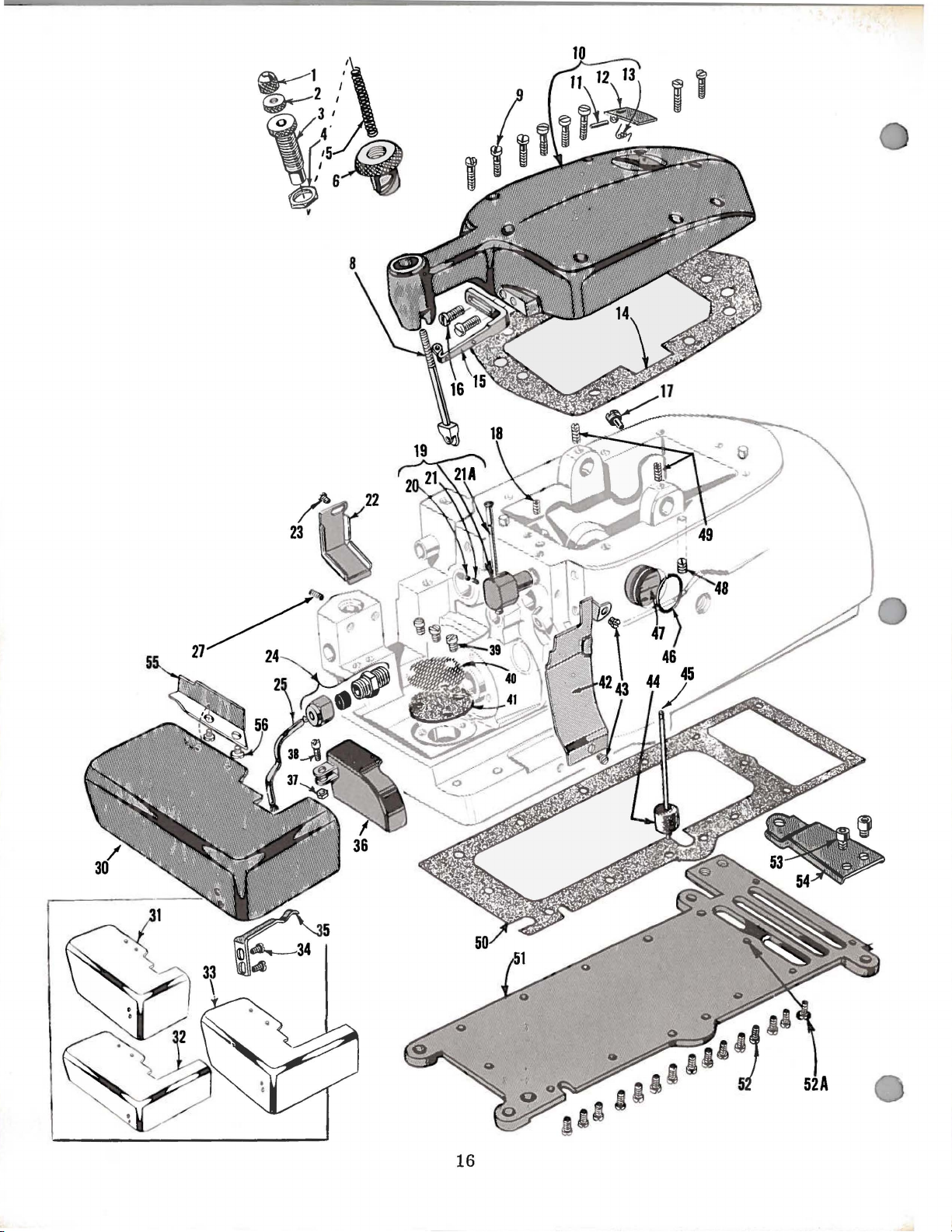
MAIN
FRAME,
MISCELLAN
E OUS
COVERS,
PLATES
Ref.
No.
1
2
3
4
5
6
8
9
10
11
12
13
14
15
16
17
18
19
20
21
21
22
23
24
25
27
30
31
32
33
34
35
36
37
38
39
40
41
42
43
44
45
46
47
48
49
50
51
52
52
53
54
55
56
A
A
Part
39557
395
57
39557
39557
39557
39556
39557
22541
39582
39582
39582
39582
39563
22569
22571
22565
29477
22743
39568
39568
39534
39594
22565
39501
39501
39501
39501
39532 A
39582 D
4
107
22569
39
39594 H
395
A
A
s
50-817
A --
E
GW
J
G
90
660-234
B
A
c
B
90
1 G
86
X
A
594
G
78
B
nssgu
39593
39
39
2
2894
22
39582
39
225
22586
22653
3
95
39578
593
660593
565
582
69
82 F
138
c
D
E
R
y
X
c
R
D - 4
F
B
E
c
F
L
M
F
B
R
243
Blk.
Description
Pr
es s
er
Spri
ng
Plun
ger
Cap Nut---Presser Spring Plunger
Presser Spring Plunger
Lock
Presse r Spring
Press
P resse r
Screws
Top
Top
Top
Screw-
Magne
Screw-
Upper
Nut -Adjusting
er F
oot Relea
Spring Pl
- T
op
Cov
er
----------
Hin
ge Pin--
1'
Oil Fill
er
Spring------
Cov
er
Gas k
Cov
er Needle Thre
Eye
let -
tic
Oil Dra
Upper
Looper
----------------unger
Cov
e r -
- ----------
Cov
er -
-
------
et----
----------in
Loop
Thread Tub
Lock
Adju
Screw---------------
se
Bushi
-------
-----------------------
-------
-----
----------
-------ad Eyelet -----
Plug
Screw--------
er
Thread
Screw -Tube Tension Spring -Looper
Thread
Feed
Bar
Screw -Feed
Oil
Tube
Feed
Bar
Screw-
Cloth
Cloth
Cloth
Cloth
Plate,
Plate,
Plate,
Plate,
Screws
Cloth
Fe
Plate Latch
ed
Mechani
Nut -Fe
Screw
Screws -Oil
Oil
Filt
Oil
Str
ainer------
Ch
ip G
uard--------Screws -Chip Gua
Oil
Gaug
Oil
Gau
Oil Gaug
Oil Sig
ht Gauge
Screws -Low
Scre
ws - Upper
Bottom Cov
ottom
B
S
cre
ws
Screw
Screws - B
Botto
Clot
----------
m Cover
h P l
Screw - - --------------
Thre
ad
Tub
e T ensi
Tube--------------------
Oil
Shield---
Ba r
Oil
- ---------- - -
Shi
el d
Coupling-------------------
Connecting Rod
Cloth
Plate---------------
semi
s ubmerged
nonsubmerged installation---------semisub
m e
rge
nonsubmerged installation
- La
tch Spring---------------
Spring-----------------------
sm
Cover-------------------------
ed Me
- Fe ed Mecha
er
chani
sm
nism
Screen and
Screen --- -
- - -
Cov
Stra
----------------
---------------
-
---------
rd--------------
e Float---------------------
ge
Indicator - - -
e Seal
Rin
g ----
---
----
- - - - - ----
er Loope
r Ba r
Looper Dri
er Gasket
Cover ---------
- B
ottom Cover----ottom Cov
Ext
ate
Fabr ic Guar d -
- ----
- ----
er Extensi
ension-
---
-----------
- - --------
--
ing Nut--------
sting Screw -----
- --------------
ng
-----
- - - -
-
-------
- - - -
---------------
-------
--
-------
----
-----------
--
-
-----
- - - -----Tub
e A
e A s
sembly------
---
on Spring
----------
Oil
Tub
e- -
------------
--
installation
d ins
er -
tallat
----
ion
-----
Cover------
ine
r------------
-
-------
- ----
- - - - -
-------ve Lev
-------
- -
--------------
--
--------
Drive
---
- - ---- -
Lev
er
Shaft------
- ---------
---
--------
-----------
on
------------
---
- - - - - -
---
- -
---------
------------ - - -
--------
-----------
- -
---
----
--
- -
- - -
---
- -
------
- - - -
-----------
--
---
- -
---
- ---- -
---
- - -
--
---
- - - - -
----
-----------
----
----
sse
mbly ----
-----
- -
----
-----
----------
--
- - -
------
------------
- - -
-------
- - -
---
- - -
----------
- -
------
----
- - -
- ---- ---- - -
-
----
- - - - - -
--------
---
------
--
--
---
-----
-
------
- - - -
- - - ---- - -
-------
---
------
----
------
- - - -
-
---
er
Shaft--
- - - - ----
---------
- - ---------
- - -
---
-----
------
--
- -
- -
--
--
- -
- -
--
- -
--
- -
--
Amt.
-
-
-
-
-
-
-
-
-
-
-
-
Req.
1
1
1
1
1
1
1
8
1
1
1
1
1
1
2
1
1
1
1
1
1
1
1
1
1
1
1
1
1
1
2
1
1
1
1
3
1
1
1
2
1
1
1
1
2
2
1
1
14
1
2
1
1
2
17
Page 18

A -
NEFDLE
B -
SPREADER -UPPER
DRIVE
C - U
D -
LOWER
PPER
DRIVE
BEARING
KNIFE
LOOPER
29
BEARING
LOOFER
DRIVE
BEARING
DRIVE
BEARING
1
18
Page 19
CRANKSHAFT
MECHANISM
AND
BUSHINGS
Ref.
No.
1
2
3
4 95
5
6 22569
6A
6B
7
8
9
10
11
12
13
13A
14
14A 77 Q
15
16
17
18
Hl
20
21
22
23
24
25
26
27
28
29
30
31
32
33
34
Part
No.
22769
39521
39521
39590
39590
39590
660-268
39590
39590
39591
39591
22894
39590
22565
39590
39522
39522
39590
97 A
22747
39591
39591
22747
39590
39591
22747
39541
666-94
39590
39590
39555
39142
39573
39573
39552
39544
A
A
H
s
R
G
J
G
H
D
K
F
p
c
B
D
B
B
A
B
N
B
c
E
G
K
L
B
L
Description
Screw,
Pulley
for
pulley
cap-------------------------------
Cap-----------------------------------------
Pulley---------------------------------------------
Screw------------------------------------------ 2
Crankshaft
Screw--------------------------------------------Spacer
Ball
Bearing Stop
Crankshaft
Crankshaft
Thrust
Crank
Crank
Ball
Bearing
Collar--------------------------------------
Collar
Ball
Bearing-----------------------------
Ball
Bearing
Washer------------------------------------Chamber
Chamber
Cooling
Cooling
Retaining
----------------------------
Housing---------------------
Fan------------------------Fan
Collar-------------------
Plate
--------------
Screw---------------------------------------------
Crankshaft
Bearing,
inner
right----------------------
Screw---------------------------------------------
Oil
Slinger
Collar
----------------------------------
Screw------------------------------------------
Crankshaft,
Crankshaft,
Crankshaft
Screw,
Screw,
Crankshaft
Crankshaft
Screw,
Stud,
Crankshaft
Screw,
Feed
Oil
Crankshaft
Crankshaft
Foot
Foot
Upper
Upper
Needle
Lower
for
for
for
Driving
Wick
Lifter
Lifter
Knife
Knife
Driving
Looper
for
Styles
for
Styles
Split
for
split
for
crankshaft
Counterweight,
Counterweight,
crankshaft
crankshaft
Counterweight,
crankshaft
Eccentric
and
Spring---------------------------------
Bushing,
Bushing,
Shaft
Shaft
Driving
Driving
Arm
Bar
39500
39500
Bearing----------------------------
bearing
counterweight------------------
counterweight------------------
split
counterweight------------------
Key
left
inner
Bushin
Bushing,
Bushing--------------------------
g,
Arm
Arm
Crank
A &
B-------------------
P &
AF
-----------------
-------------------------
right
middle--------------------
bearing
left-----------------------
---------------------------left-----------------------
left----------------------right----------------------
Bushing,
Bushing,
Bushing-------------------
---------------------
--------------------
-------------------------
left
---------------
right--------------
Amt.
Reg.
1
1
1
1
3
1
1
1
1
1
1
1
2
1
1
1
2
1
1
1
2
2
1
1
2
1
1
2
1
1
1
1
1
1
1
1
1
1
19
Page 20
20
Page 21
Ref.
No.
ar
P
No.
NEEDLE
t
DRIVE
AND
FEED
Des
MECHA NISM
cripti
on
Amt.
Req.
---
1
2
3
4
5
6
7
8
9
10
-I
1
12
13
14
15
16
17
18
19
'
i
20
21
22
23
24
25
26
27
28
29
30
31
32
(3
'3
34
®
36
37
38
39
40
41
42
;rn
44
45
46
47
48
49
50
51
52
87
39578
22569 B
8372
39578 p
22565
39535
39535
53634
22569
39535
39
535
5
3634
22569 B
22569 G
39534
39538
39534
395
26 B
39526 p
39526 D
22 528
39505 c
3950
5
3950
5 E
22797
39534
39505 B
39505 p
39 5
39540-10
39 536 A
395
39 536 z
39536
39 536 c
39536
14077,..
3955
3
22
3955 1 F
395
225
39568
39568
39552
39552 A
39
22587
395
05
93 A
40-12
18
9552
596 E
50-774
63 'G
28
64
88 B
552 E
94 N
77
A
D
E
B
1 A
A
N
c
J
R
A
F
c
c
B
D
c
H
G
.--
Sc
rews -Fabric
Fabric
Screws Mount
Fabric
Scr
eed Til
F
Ma
Feed
Sc
Feed Bar Gui
Differential Feed Ba
F ee d
Sc
S
crews -Thru
D
ifferential Feed B
FeedLiftBlo
Differen
Di
16
Di
12
S
ame
Screw - D
Chainin
Chainin
Chaining Fe
Screw -Chaini
Ma
Mai
16
Ma
Same
Screw D
iffere
Diff
Ma in F eed D
Ma
Nu
N
ut
Feed Bar Drivi
F
eed
Nut -
Needle Clamp
Nee-dle---------Needle
B
lk.
Nee
Needle Th
Sc
r ew -
Sc
r ew - Looper Th
L
oop
L
oop
Needle
Needle Driving Arm Crank- - - Needle Dri
Oil Spla sher
Screw
Guard-------
Mounting Bracke
ing
Brac
Guard Mount
ew
-Adjust
ting
in
F eed Bar Gui
Bar Guid
rew
s -
Feed Bar Guide , left------ - ----
Bar Guide Washer
rews
- Feed B
tial F eed B ar--- -
fferent
fferential Feed Do
in
in F
in Feed
t - C
s -
S
Stop P in -Need
dle
Screw -
Scr e ws -
ial Feed Dog,
teeth
to inch - - - -
teeth to
as 39526
iff
g F
eed Dog, for
g F ee d Dog, fo r Style
Feed Ba
n Feed Dog, for Style s 39500
teeth
to
eed Dog,
a s 39505 B , except 20 tee
Main
nti
al Feed
er
ent
ial
Bar Driving Connection- ---------------
rankshaft---
Fee
d Bar Dr iving Studs - -
Bar Driving Studs-----------
Needle Clamp St
Dr i
ving Arm------------- -
cre
w-
Clamp
read
Needle
er T h read
er
Thread
Dr iving Arm Crank Thru
vin
- O
il
Splash
Gua
r d
-------------------------
---
-----------------t -
-----
ket Was
ing
Adju
e Wa s he r , lef
de Bloc
st Was
ck
---
inc
h----------------------
B, except
er ential Feed Dog
ed Dog, for
ng Feed Dog
r - -
inc
h---------------------
for Style 3
Feed Dog----------
F ee d
riving Eccent r i
ng
Washer ------
Needle Driving Arm----
Stud --- - ----
Cam
Th read Cam P
Pull-off- - ------- Pull-o
Loop
er
g A r m C
Connecting
---------
hers---------
ing
Bracke
Pin ---
sting Pin - - ----
de, left
ks -
-------------------------
r Guid
s, righ
ar
Gui
de,
her
--------------
ar Thr us t Washer-----------
- -
---
- - -
for
--------------------
g, for Sty
Sty
Sty
---·------------------------------
Dri
ving E ccentric- -
Bar Driving
- -
-------
Connections B u
ud-
-------------
le Dri
rea
vin
Pull-off-----------------------
d P
ff Leve r - -
Thread Pull-off Lever
rank Connec
Ro~
- ----
er
---
- - - -------
t - - - -
-----------
----t------
e, right---- - -------------- - 1
t---
rig
ht ---
----------
---------------Sty
les 39 5
le
20 tee
ull-off
th
------------------------ 1
le
39500 A -----39500
le
39500 P ----
---------
9500
P,
th to
Connecti
c------
-------------
-------
- -
-----------------------
-----
g A
rm
-------ull-off--- - - -
---------------
-----
st Washer----
--------
- ---- ----
----
- - - -
-
- ---- -
----
- - - - -
39500
to inch ---
A,
shings
- - -
--------------
tin
---------------
--
---------
--------
--
- -
--------
------------------
- - -
---------
-----------------
00
P,
B & AF - - ---- ---- - - 1
-
------------
B & A F ,
12
tee
inc
-
-------------
------on--------
----------
-------------
----------------
---
-------
--
- - -
-------------
- -------
---
g R
-----
-------------
------------
--
-------------
--------
--------
-
---------
-
------------
- - -
A,
B & A F ,
- - -
- - - ---- - - ---- - 1
- - -
-----
- ---- -
-
----------
th
to inch ---
h---------- - - - - 1
- - - ---- -
--------
- - -
----------
-----------
- -
---
- - -
----
--------
------
-----
--------------
-----
--------
od--------
----------
-----
--------
-
-----
-----
- - - -
-
------
- - -
- - ----
---
- - - - -
----
- - - - - 1
-------
------
---
-------
--
---
- - - - - - 1
----
-------
-
---- 2
- ---- - 2
- - - - 1
---
---
------
---
- - - - - - - 1
- -
- - - ---- 1
- - - - - - - 1
---- -- 1
----- - - - 2
- -
------
-
-----
- - -
- -
-------
- - 1
- 2
- - - - 1
- - 1
---
--
- 2
--
--
- - 2
--
- - 2
--
3
--
- - - 1
- - 1
- - 1
---
1
1
---
1
-
--
1
- 1
--
1
--
1
- - 1
--
1
---
1
- - - 1
- - 2
--
- 1
- 1
--
1
- - 1
--
1
--
- 1
1
- 1
- 1
--
1
- 2
---
1
1
2
2
1
1
2
2
1
21
I
Page 22
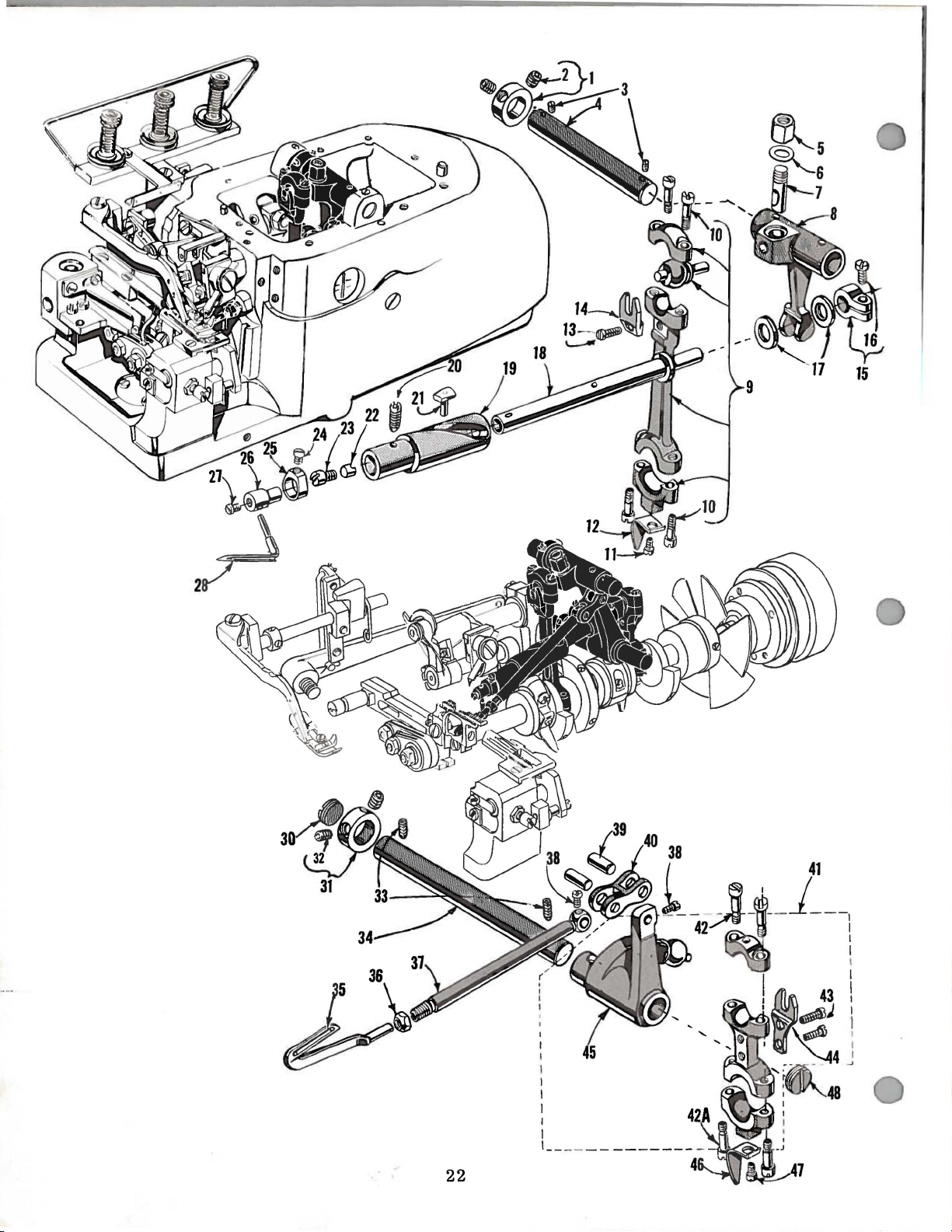
Page 23
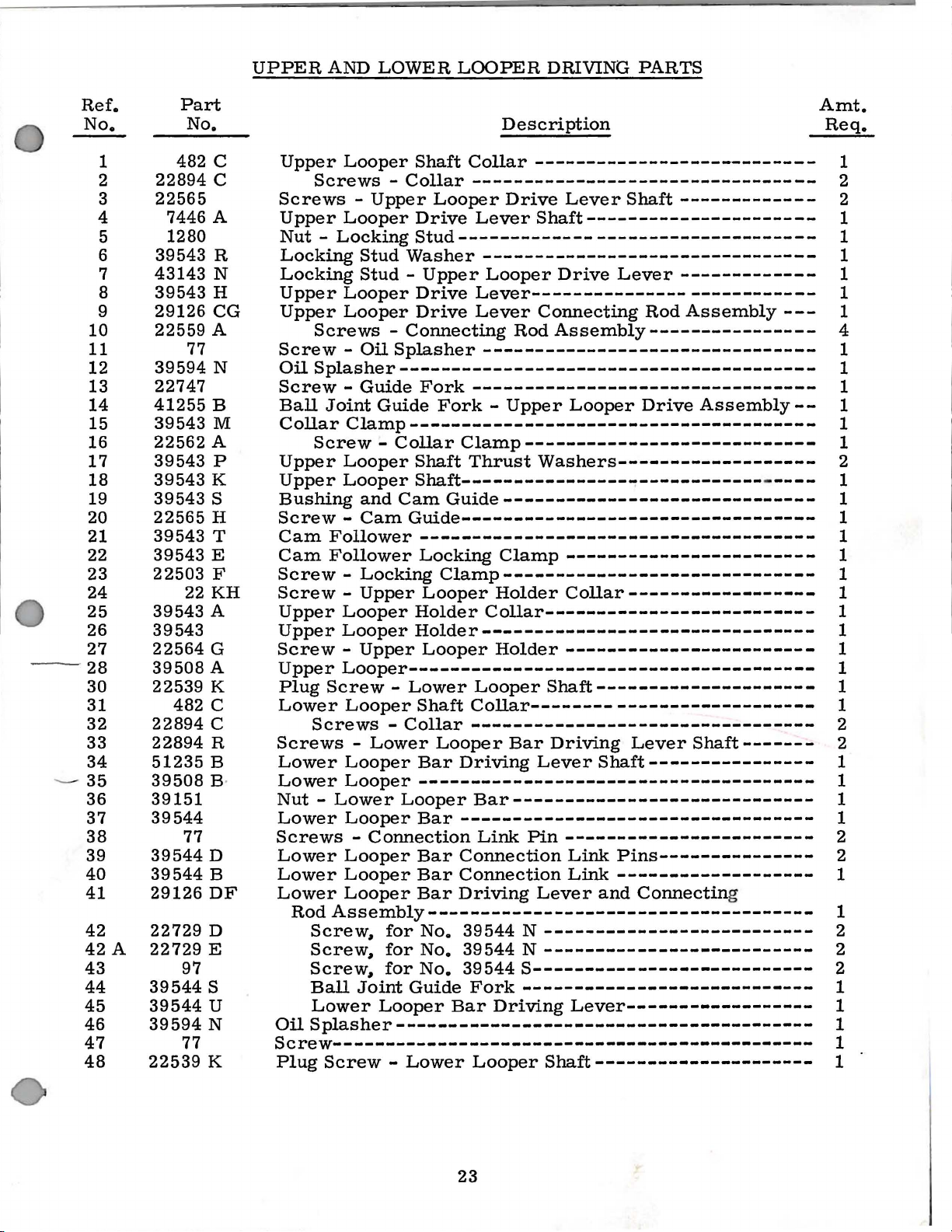
UPPER
AND
LOWER
LOOPER
DRIVING
PARTS
Ref.
No.
1
2
3
4
5
6
7
8
9
10
11 77
12
13
14
15
16
17
18
19
20
21
22
23
24
25
26
27
28
30
31 482 c
32
33
34
---
35
36
37
38
39
40
41
42
42
A
43
44
45
46
47
48
Part
No.
482
22894
22565
7446 A
1280
39543
43143
39543
29126
22559 A
39594
22747
41255
39543
22562
39543
39543
39543
22565
39543
39543
22503
22
39543
39543
22564
39508
22539
22894
22894
51235
39508
39151
39544
77
39544
39544
29126
22729
22729
97
39544
39544
39594
77
22539
c
c
R
N
H
CG
N
B
M
A
p
K
s
H
T
E
F
KH
A
G
A
K
c
R
B
B·
D
B
DF
D
E
s
u
N
K
Amt.
Description
Upper
Screws -Upper
Upper
Nut -Locking
Locking
Locking
Upper
Upper
Screw -Oil
Oil
Screw -Guide
Ball
Collar
Upper
Upper
Bushing
Screw -Cam
Cam
Cam
Screw -Locking
Screw -Upper
Upper
Upper
Screw -Upper
Upper
Plug
Lower
Screws -Lower
Lower
Lower
Nut -Lower
Lower
Screws -Connection
Lower
Lower
Lower
RodAssembly-------------------------------------
Oil
Looper
Screws -Collar
Looper
Stud
Stud -Upper
Looper
Looper
Screws -Connecting
Splasher
Joint
Clamp---------------------------------------
Screw -Collar
Looper
Looper
and
Follower
Follower
Looper
Looper
Looper---------------------------------------
Screw -Lower
Looper
Screws
Looper
Looper
Looper
Looper
Looper
Looper
Screw,
Screw,
Screw,
Ball
Splasher
Joint
Lower
Shaft
Drive
Stud----------------------------------
Washer
Drive
Drive
Splasher
---------------------------------------Fork
Guide
Shaft
Shaft-----------------------------
Cam
Guide----------------------------------
-------------------------------------Locking
Holder
Holder--------------------------------
Shaft
-Collar
Bar
--------------------------------------
Looper
Bar
Bar
Bar
Bar
for
No.
for
No.
for
No.
Guide
Looper
----------------------------------------
Collar
---------------------------------
Looper
Lever
-------------------------------Looper
Lever--------------------------Lever
--------------------------------
---------------------------------
Fork -Upper
Clamp----------------------------
Thrust
Guide------------------------------
Clamp------------------------------
Looper
Collar--------------------------
Looper
Looper
Collar---------------------------
---------------------------------
Looper
Driving
Bar-----------------------------
---------------------------------Link
Connection
Connection
Driving
39544 N -------------------------39544 N --------------------------
39544
Fork
Bar
--------------------------
Drive
Rod
Clamp
Holder
Holder
Bar
Driving
Lever
Shaft----------------------
Drive
Connecting
Assembly----------------
Looper
Washers-------------------
------------------------
Collar------------------
------------------------
Shaft---------------------
Driving
Lever
Pin
Lever
S---------------------------
----------------------------
Shaft----------------
-----------------------Link
Link
and
Lever------------------
Lever
Pins---------------
-------------------
Shaft
Lever
-------------
-------------
Rod
Assembly
Drive
Connectin
Assembly--
-
Shaft-------
g
----
---
Req.
1
2
2
1
1
1
1
1
1
4
1
1
1
1
1
1
2
1
1
1
1
1
1
1
1
1
1
1
1
1
2
2
1
1
1
1
2
2
1
1
2
2
2
1
1
1
Screw---------------------------------------------- 1
Plug
Screw -Lower
Looper
Shaft---------------------
1
23
Page 24

Page 25
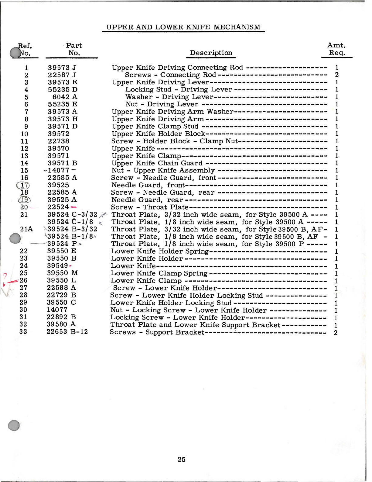
UPPER
AND
LOWER
KNIFE
MECHANISM
1
2
3
4
5
6
7
8
9
10
11
12
13
14
15
16
<I'D
18
diD
20
21
21A
22
23
24
25
1
~-26
~
27
28 227'29 B
29
30
31
32
33
Part
No.
39573
22587
39573
55235
6042
55235
39573
39573
39571
J
J
E
D
A
E
A
H
D
39572
22738
39570
39571
39571
-
14077
22585
B
-
A
39525
22585
39525
22524
39
A
A
-
524
C-3/32 _/·
39524·t-1/8
).
39524
~
39524B-1/8
39524
39
39
39549
39p50
39
22588
39550
550
550
550
B-3/32
P
~
E
B
·
M
L
A
C
..,.
14077
22892
39580
22653
B
A
B-12
Upper
Knife
Screws -Connecting
Upper
Knife
Locking
Washer -Driving
Nut -Driving
Upper
Upper
Upper
Upper
Knife
Knife
Knife
Knife
Screw -Holder
Upper
Upper
Upper
Knife-----------------------------------------Knife
Knife
Nut -Upper
Screw -Needle
Needle
Guard,
Screw -Needle
Needle
Guard,
Screw -Throat
~
Throat
Throat
Throat
Plate,
Plate.
Plate,
ThroatPlate,
Throat
Lower
Lower
Lower
Lower
Lower
Plate,
Knife
Knife
Knile-----------------------------------------Knile
Knife
Screw -Lower
Screw -Lower
Low
er
Knile
Nut -Locking
Locking
Throat
Screw -Lower
Plate
Screws -Support
Description
Driving
Connecting
Rod
--------------------
Rod---------------------------
Driving
Stud -Driving
Lever-----------------------------
Lever-----------------------
Lever----------------------------
Lever
Driving
Driving
Clamp
Stud
Holder
Block -Clamp
-------------------------------
Arm
Washer-----------------------
Arm------------------------------
-------------------------------
Block------------------------------
Nut----------------------
Clamp-----------------------------------Chain
Knife
Guard------------------------------
Assembly
Guard,
front---------------------------
---------------------------
front-----------------------------------
Guard,
rear
---------------------------
rear-----------------------------------
Plate---------------------------------3/32
1/8
3/32
1/8inchwideseam,
1/8
Holder
inch
inch
inch
wide
wide
wide
seam,
seam,
seam,
for
for
for
Style
Style
Style
forStyle39500B,AF-
inch
wide
seam,
for
Style
Spring-----------------------------
Holder----------------------------------Clamp
Spring-----------------------------
Clamp-----------------------------------
Knile
Knife
Holder
Screw -Lower
and
Holder---------------------------
Holder
Locking
Lower
Bracket-------
Locking
Stud
Stud-----------------------
Knife
Knife
Knife
Holder--------------------
Support
Holder
.:
----------------------
---------------
Bracket-----------
39500 A ----
39500
39500
A-----
B,
39500 P -----
--------------
AF-
Amt.
Req.
1
2
1
1
1
1
1
1
1
1
1
1
1
1
1
1
1
1
1
1
1
1
1
1
1
1
1
1
1
1
1
1
1
1
1
1
2
25
Page 26

26
Page 27
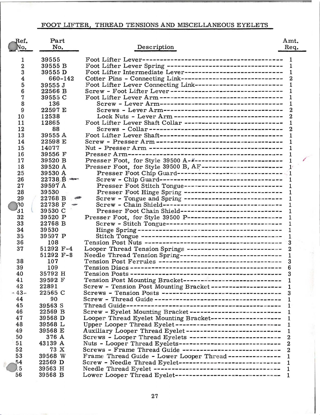
FOOT LIF
TER,
THREAD
TENSIONS
AND
MISCELLANEOUS
EYELETS
-"
1
2
3
4
5
6
7
8
9
10
11
12
13
14
15
16
17
18
25
26
27
28
29
~0
J1
32
33
34
35
36
37
38
39
40
41
42
4344
45
46
47
48
49
50
51
52
53
!i4
.5
56
l
Part
No.
39555
39555
39555
660-142
39555
22566
3955
136
22597
12538
12865
88
39555
22598
14077
39556
39520
39520
39530
22738
39597
39530
22768
22738
39530
39520
22768
39530
395
97
108
51292
51292
107
109
35792
39592
22891
22 5
65
90
39563
22569
39568
39568
39568
376
43139
73
39568
22569
39563
39568
B
D
J
B
5 c
E
A
E
F
B
A
A
...-
:B
' A
B
F
c
p
B
p
F-4
F-8
H
F
c
s
B
D
L
E
A
A
X
w
D
H
B
Foot
Foot
Foot
Cotter
F
Screw -Foot Lift
Foot Lif
Foot Lifte
Foot Lif
Screw -Presser
Nut -Presser Arm ------------
P r
Presser
Press
~
~
-
P
Tension
Looper
Ne
Te
Te
Te
Te
Screw -Tension
Screws -Tension
Screw -Thread
Thread
Screw
Looper Thre
Upper
Auxiliary
Sc
Nu
Screws -Frame
F
Screw -Needle
Ne
Low
L i
Lifter
Lifter
oot Lifter
Screw
Screws -Lever
Lock
Screws -Collar-------------------
esse
er
Presser
Screw -Chip Gua
Presser
Presser
Screw -Ton
Scr
Presser
res
ser
Sc
rew -Stitch
Hinge
Stitch
edle
nsion
nsionDiscs---------------------------------------
nsion
nsion
r e
ws -Loop
ts -Looper Thre
rame Thread
edle
er
Description
fter Lever--------
Lever
Intermediate
Pin
s -
Lever
ter
Le
- Le
Nut
s -
r L e
ter
Lever
r A r
m----------------------Foot, for Styl e 39500 A-¥Foot,
Foot
Foot Sti
Foot
ew -
Thread
-Eyelet
Looper
Thread
Looper
Chain Shie
Foot
Foot,
Spring----------------Tongue
Post
Thread
Post Fer
Posts--------
Post
Guide-----
Nuts
Mounting Bracket------
ad
Looper
Sprin
Connect
Connect
er Le
ver
Arm---
ver
Ar
m-----------------------------------
Arm----------------
Leve
r A r
ver
Sha
Shaft--------
Arm-----------------
for Styl
Chi
p G
rd--
tch Tongue-------------
Hin
ge Spri
gue
and
Cha
in
for
Styl
Ton
--------------
-----------------
Tension
Tension
rul
es
Po
st
Posts
Gu
ide - ---- -
---·
Mountin
Eyelet
Thread
er
Thread
Thread
Guide -
Thread Eyel e
Ey
Thread Eyelet----------------
Eyelet------
Thread
ad
elet
----------
-
--------------------------
g - - - -
Lever-----------------
ing L i
ft
e 395
ld----------------------e 39 500 P -
gue
Moun
g Brack
Mounting
Eyelets------------
Low
nk------
ing
ver----------------------------
- - ----
m----------------------------
Collar
00
uard
--
---------ng - -
Spring ---------Shield----------------
----------
Sprin
Spr
ing
-----------------------
-
----------ting
-----------------
-------
Eyelet--------------
Eyelets
Guide
er
------------
-
----
Link----
------
--------------------
-
-------
-
----
------
B,
A~----------
---------
---------------
---------
- - -
-
----------
-
--------------
-
gs
------------------------
-------------------------
-
--------------
- -
Bracket--------------------
---------------
-
-------------
et--------------
Bracket---------
-
-------------------
---------------
----------------------
Looper
t--------
-
------
Threa
---
-
----------------
------------------
- - -
-------
- ----
--
-
----
-
--------------------
-
--------------------
-------
-----------
------------
-
---------------
-
-----------------
-
------------------
-
------------------
-
------------------
------
----
- - - - - -
- --------------
---------- -
-
-----
-
-------------
---- -
-
--
-----
d--------
- -
------
---------------
---- - ---- ---- - 1
--
-
----------
-
-----
-
------------
---------
------------
- - -
----------
- - - ---- -
- - - - - - - - -
---
- -
- - -
----
-
--------
-
------
-
-
-----
-------
--------
- -----------
-
---
-
------------
-
--------
----
------- -
- -
-
-------
---
--------
---
- - -
----
--
---
----
------
-
-------
-
-------
-
- - - -
- -
----
- ---- - 2
- -
-----
Amt.
Req.
---
---
-
---
-
--
-
--
---
----
--
--
---
-
---
- - - - 1
- - 3
- - - 2
- -
--
-
---
--
- 3
-
--
---
- 1
---
- -
--
- - 2
--
-
--
1
1
1
2
1
1
1
1
2
2
1
2
1
1
1
1
1 /
.1·
1
1
1
1
1
1
1
1
1
1
1
3
6
3
1
1
1
1
1
1
1
2
1
1
1
27
Page 28

28
Page 29

THREAD
STAND
AND
MISCELLANEOUS
TOOLS
Ref.
No.
1
2
3
4
5
7
8
9
10
11
12
13
14
15
16
21233
21261
21261
21261
21377
21377
21695
39556
39556
605
39595
39598
52978
21113
21104
21130
22650
22650
21104
WA9A
21227
21202
21388
BR
M-360
M-380
M-400
BA
BF
u
B
c
J
Part
No.
F
v
69
s
W-3
CB-4
CE-6
AA
652
J-24
652 J -16
651
A-16
116
660-240
BF
AU
ACCESSORIES
Thread
Felt
Spool
Cone
Thread
Washer -Thread
Washer -Thread
Lock
Nut -Thread
Wrench,
Thread
F
eed
Screw
Socket
Light
No. 1
No. 1 "V"
No. 1 "V"
Tray, 1 3/4
Tray,
Finger
Presser
Presser
Presser
Isolator,
Knife
Ch
Fixture
chines
table
table ins
installations.
tion
ip
driven
"V"
installations.
1'
3/4
extended
Protector
Arm
Arm
Arm
rubber.
Grinder,
Disposal
Description
Eyelet
Pad
Pin-------------------------------------------------
Support
Screws -Cone
Screw -Cone
Stand
Washer
Tweezers
Eccentric• Extractor
Driver,
Wrench,
AVAILABLE
Assembly,
Belt,
Belt,
tallations.
Belt,
inches
inches
Chain
Chain
Chain
Chute.
and
Support
-------------------------------------------------
---------------------------------------------
Rod
---------------------------------------------
Stand
for
9/32
by
"Electro
36
inches
38
inches
40
inches lon
high, for semisubmerged
high,
to
right.
Cutting Kni
Cutting
Cutting
complete.
Support--------------------------------
Support---------------------------------
----------------------------------------Stand
Stand
Rod------------------------------------
inch
-----------------------------------------
1/4
inch
for
3/8
includin
lon
lon
for
Rod
-----------------------------
Rod
--------------------------------
Rod
--------------------------------
nuts---------------------------------
Hook----------------------------diameter,
inch
nuts
AS
EXTRAS (Not
!f
Drive'
g, for
g,
for semisubmerged
g,
for
s e
misubmerged
fe , l
Knife,
Knife
Screws (two
11
inches
holding
Illustrated)
blue
lens,
which
upper,
suppli
fully
submerged individu
nonsubmerged
installations.
installations
ower
.
long-------------
feed
eccentrics------
machine
es
the
individual
individu
needed).
mountin
current.
al
with
g f
al
power
power
power
front
orma-
tabl
Amt.
Req.
3
3
3
1
3
1 6
1
1
1
1
1
1
1
1
1
1
e
s e
c-
21371
21371
21371
21371
21371
21371
21371
21371
21371
21371
21371
NK
PJ
-48
RD-48
RF-48
RJ
-48
RL-48
RG-48
RK-48
RC-47
RE-47
RH-47
3/4
3/4
3/4
Individual
Table
individual
Nonsubmerged -no
Table
Table
no
chip
Table
Table
Table
Table
Table
for
line
Nonsubmerged -no
Table
Table
Top,
Top,
Top,
Top,
Top,
Top,
Top,
Top,
Top,
Top,
Power
48
power
same
same
chute;
same
same
same
same
47
shaft
same
same
x 20 x 1
3/4
installations:
Table
table
chip
except
except
except
except
except
except
x 16 x 1
chip
except
except
3/4
inches,
installations:
chute;
Nonsubmerged;
Nonsubmerged
Semisubmerged;
Semisubmerged;
Fully
Fully
Nonsubmerged
Semisubmerged
Submerged
Submerged
3/4
chute
inches,
for
-
29
Belt
Slot
Rig
ht Edge
of
Board
14
7
1/2 inch
7
1/2
10
1/2
7
1/2
7
1/2
10
1/2
71/2inch
7
1/2
7
1/2
to
i
nch
inch
inch
inch
inch
inch
inch
inch
Cloth
F
ront Edge
Board
of
3/8
3
3/8
2
1/4
2
1/4
2
1/4
2
1/4
3/8
3
21/4inch
Plate to
inch
inch
inch
inch
inch
inch
inch
inch
inch
Page 30

NUME
R I C A L I N D E X
OF
PA
RT
S
Part
No.
WA9 A ••••••••••
18
•••.....•..•
22
KH •
28
50-774 Blk
50-817 Blk
69
73
77 ••• • .
77 Q ••••••••••
86
87
88
88
90
93A •••
95
97
97
107
10 8 .••••••.••••
109
116
136
138
376 A ••••••••••
482
651
652
652
660-142 ••.
660-234
660-2
660-243
660-268
666-94 •••••••••
1280
6042 A •••
7446 A •••
8372A ••• ••••••• 21
12538 •••••••••••
12865
14077 ••••••
2110
21104
21113 D ••
2111
211
30
21202 •••••
212
27
21388
22
503 F • •••• •••• • 23
22
524
22539
225
41
22
559 A
22562 A ••••••••••
225
64
225
64 G
225
65 ••••
22565 B • • • • ••••••
22 565
2565 F ••• •••
2
565
22
566 B ........
22
22569
2256
2256
22 569
••••••••
.•..
. . .
s
.......
X •
•••••••••
.•.••••
X
••••••••••
••••..••••••
••••••••••••
B
••••••••••
••.•.•.•••••
•••••••
•••••.••.•••
••••••••••••
A •
•••••••••
•.••••••.•••
.•.•••••••••
•••••••..•••
••••••••••••
••••••••••••
c .... .
A-16 •••••
J-16
••••••••
J-24
• •
••••••
••••••••
40
••••••••
••••••
••••••••
. •
••••••.•••
•••••••
•••••
••••
• • • •••• • 27
4 v ..
AA
3 E
BF •••
AU
• •
K • • • •
• • • •
•••••••••••
c .
H •
•••••
9 A
9 B
• • •
..
.. . .. . 29
• •
•••••••
• •••• • • • 29
••••••••
W-3 ••••••••
• •••• • • 29
••••••
••••
••••••••••
••••
•••••• • • 17
•••
••••••
•••••
•••
.......
•••
• •
• •
•••••••
....
. . . .
c .........
.....
•••
• • 21
•••••
....
.....
• • 29
•••••
• • 17
• • 23
•••
• • 29
• • • • • 29
••
••••• 23
• • • • • 17
..
•••
•••
. . 27
•• ••
• • • 17
..
Pa
ge
No.
29
21
23
21
17
29
27
21,23
19
17
21
27
21
17,27
21
19
23
19
27
17
27
29
2 7
17
27
23
29
29
27
17
29
19
19
23
25
• 27
21,
25,
29
29
29
25
23
• 23
23
• 21
,23
17
27
• 19, 21
• 23
• 19, 21
17, 21 , 27
. 17
Part
No.
22569 D •••••••••
22569 G •••••.••
22571 E ••••••••••
22585
A •
22586 R ••••••••••
22587 J ••••••••••
22588
A •••••
22596 E •••
22597
E ••
22598
E •
22650
CB - 4
22650 CE-6
22653 B-12
22653
D-4 .......
22729 B ••••••••••
22729 D ••••••••••
22729 E ••••••••••
22738
••••••••••••
22738 B ••••••••••
22738 F •••••• •
22743
•••
22747
• •
22747
B • • •
22
768 B ••••
22
769 A ••••••••
22797 A ••
2891. •••••••••••
2
89
2 B •
22
894
c .......
22
22
894 D •••
22894 R
29126 CG
29 126 DF
29477 GW
35792 H
142 G .......
39
39151.
395
39501 A
39501 B • • ••••••••
395
39 505 ••••
395
27
395
395
395
39505
395
3950
39520A
395
3952
39521 ••••
3952
3
3952
39524 B-3/32 ••• • • 25
395
39
3
39524 P • • • • • • • • • • 25
3
39
395
39 52 6 D
3
3
3
395
•••• • •••• • • 23
01.
• • •
01 c ..
05 B
05 c
05 D,
05 E
P •
08 A •••••
8 B ••••
20 B ••••••
0 P ••• • •••••
1 A ••••
9522
B •••• • •••••
2 c .
24 B-1/8 ••
524 C-3/32
95
24 C-1/
9525
•••••
525
A, ••• •••• • • 25
26 B • • • • • • • • • • 21
9526 P ..
9530
• • • ••••
9530
A • • • •
30 c . ....
• • 21
•••••••••
••••
• • •
••••
•••••••
•••••••••
......
......
•••••••
•••••••
• • •
• • •
•••••
•••
•••
•••
• • ••••
••••••••••
•••••••••
.. . 23
•••••
• • •
•••••
..
....
..
......
• • •
•••• ,17
•••
••••••
..
•••••• • • 17
.......
.
........
••••••
...
....... 21
...
......
••••
••
••••
• •••• • • •
• • • • ••••••
'.
••••••
•••
••••••
•••
••••••
••••
• •••• • • • 19
••••••
......
.. . 19
• • • • 25
•• , ••
8 • • • • • • 25
•••
••••
...
.....
•••••
••••••
....
Page
No.
,17,
27
17
25
I7
21,
25
• 25
21
• 27
27
29
29
25
,17
25
23
23
25
27
27
17' 29
23
19
27
• • 19
21
27
25
• • 19
• • 17, 23
..
23
23
• 27
, 19
..
17
17
17
••
21
. 21
• • 21
21
21
• • 23
23
••
27
27
• 27
19
19
25
25
21
21
27
27
. 27
Part
No.
39532 A ......
39534
••••••••
39534 G ......
39534
H
39534 R ......
39535
39535 B ......
39535
39535
39536 A ....
39536 B ......
39536
39536 E ......
39536
39538
39540-10 .••••
39540-12
39541
39543
39543 A ••••••
395
39543 H ••••••
39543
395
395
39543 R ....
3954
395
3954
395
39
39
395
39
39
39550 B
39
39550 E
3
3955
39551 A ......
39551 F ......
39552 •••• ••
39552 A ......
39552
39552
39552 E ......
39555
39555 A ••••••
39555 B ••••••
39555
39555 D ••••••
39555
39555 J ••
39556 A ......
39556 F ....
39557 ••
3955
39557 B ......
395
39557
39557
39563 F ......
39563
39563
39563
39568
39568 B ......
3
......
• •
••••••
c
.....
D .
...
..
. . 21
c
......
z
......
••••••••
•••••
••••••••
••••••••
43 E . .
43 M
43 P
43 T
44 B •
544
544 L ••
44
54
549 • •
55
955
57 c .
9568 D •••••• 27
....
K • • • •
.....
.,
....
3 s
......
....
4 • • •
•••
••••
D • •••••
••••
s
......
4 u
......
•••••.
......
0 c
......
......
0 L • • •
0 M
7 A ......
.....
B ......
c
......
••••••••
c
......
E ,
•• ••
• •
••••
•••
...
E, .....
F • •
••••
G •••••
H ....
s .
...
A . . .
...
••
..
..
• • 23
• • 21
••
..
••
..
..
..
Pa
No.
17
21
21
21
17
21
21
. 21
21
21
21
21
21
21
21
21
19
23
23
23
23
23 J
23
23
23
23
23
• 23
23
19
23
23
25
25
25
25
25
25
21
21
21
19
21
21
27
27
27
27
27
• 19
27
17
27
17
17
17
17
17
17
17
• 21
27
27
21
27
ge
Part
No.
395
68 E .......
395
68 G ......
39568 J .......
39568 L •••••
3
9568
3956
39570
39571 •••••••••
3957
39571 D •••••••
39572
39573 A •••••••
39573 E .......
39573
39573
3957
3957
3957
39578 F .......
39578
39578 R
39
580 A •••••••
39582 A
39582
39582 F
82
395
395
82 M .... ,.17
39582
39
582
395
82 Y •
3
959
3
9590
395
90
39 590 F • ••••• • 19
3959
3959
3959
3959
39590 N •
39590 P ....
39 590
3959
395
91
3959 1 A .......
3959
395
91 G .......
39591
3959
39593
395
93 D
39593 E ••••••• 17
3959
395
94 G •••••••
3959
395
94 N ••••••• 21,23
39597 A
3959
41071 G
255
41
43139 A ••
43143 N ••
51235 B
51292 F - 4
5129
52
35 D
5
55235
Pa ge
N
27
.
17
17
• •
N •
8 w
•••••••••
1 B
•••••••
•••••
H • • • • • • •
J .
3 K •••••••
3 L •
8 B
......
P • • •
•••••••
....
D • •
• • •
L • • •
8 •
x ..
0 • • • ••••••
c
.......
D ....
0 G
.......
0 H
••••
0 J ...
0 K •• • • • • • 19
R • • •••••
0 s
...
•• ••••• • •
1 B
•••••• • 19
H • • • • • • • 19
2 F
•• ••
c .......
•••••• •
4 • • •••••••
4 H .
....... 27
7 P •••
••••
B .
..
2 F - 8 • • • • • 27
•• •• ••• 25
E .......
27
••••••
21
......
27
25
25
25
25
• • • •
25
25
25
25
....
..
25
19
••••
••
19
. 17
17
•••• 21
21
25
...
17
••••
• 17
••••
17
•••
• 17
•• ••
• •
17
....
. 17
••• •••
••••••
.. ....
...... 23
17
19
19
...
19
19
• • • 19
....
19
19
..
, 19
19
....
19
19
19
19
• • •
27
17
17
17
17
17
•• ••
27
•••
17
• • • • • 27
• • • • • 23
.. ..
, 23
• •••• 27
25
o,
30
 Loading...