

Page 1
INDUSTRIAL
·
FINE
ST
QUALITY
STYLES
37500-1
37500-5
37500-6
37500-8
®
~~
L E W I S® • C 0 L U M B I A®
SEWING
MACHINES
37500-9
CATALOG
No.
194-19
Second
Edition
CLASS
SINGLE
THREAD
BLINDSTITCH
NON-SKIP
37500
CHAINSTITCH
MACHINES
STITCH
UNION SPECIAL
CHICAGO
CORPORATION
Page 2
Catalog
No.
INSTRUCTIONS
FOR
194-19
ADJUSTING
LIST
37500-1
37500-5
Second
AND
AND
OF
FOR
CLASS
STYLES
37500-9
OPERATING
PARTS
37500
37500-6
37500-8
Edition
Union
Rights
Copyright
Special
Reserved
1973
by
Corporation
in
All
&
UNION SPECIAL CORPORATION
INDUSTRIAL
Printed
SEWING
CHICAGO
in
2
MACHINES
U.S.A.
1976
Countr
i
es
January,
1979
Page 3
Each
the
style
machine
UNION
plate
is
stamped
SPECIAL
located
in
IDENTIFICATION
LEWIS
on
the
right
the
base
at
machine
end
of
the
back.
OF
MACHINES
carries a style
the
machine
number
base.
The
which
serial
is
stamped
number
of
into
each
This
catalog
It
can
also
ences
to
direction,
operator's
Single
Left
Thread,
to
Right
Adjustment,
to-Read
and
Indicator
Removing
(177. 8 mm),
37500-1
Equipped
material
also
felling
103-EFm-1
37500-5
For
garments.
37500-6
For
heavy
37500-8
Equipped
trousers.
37500-9
Fitted
where
103-EFl-1.
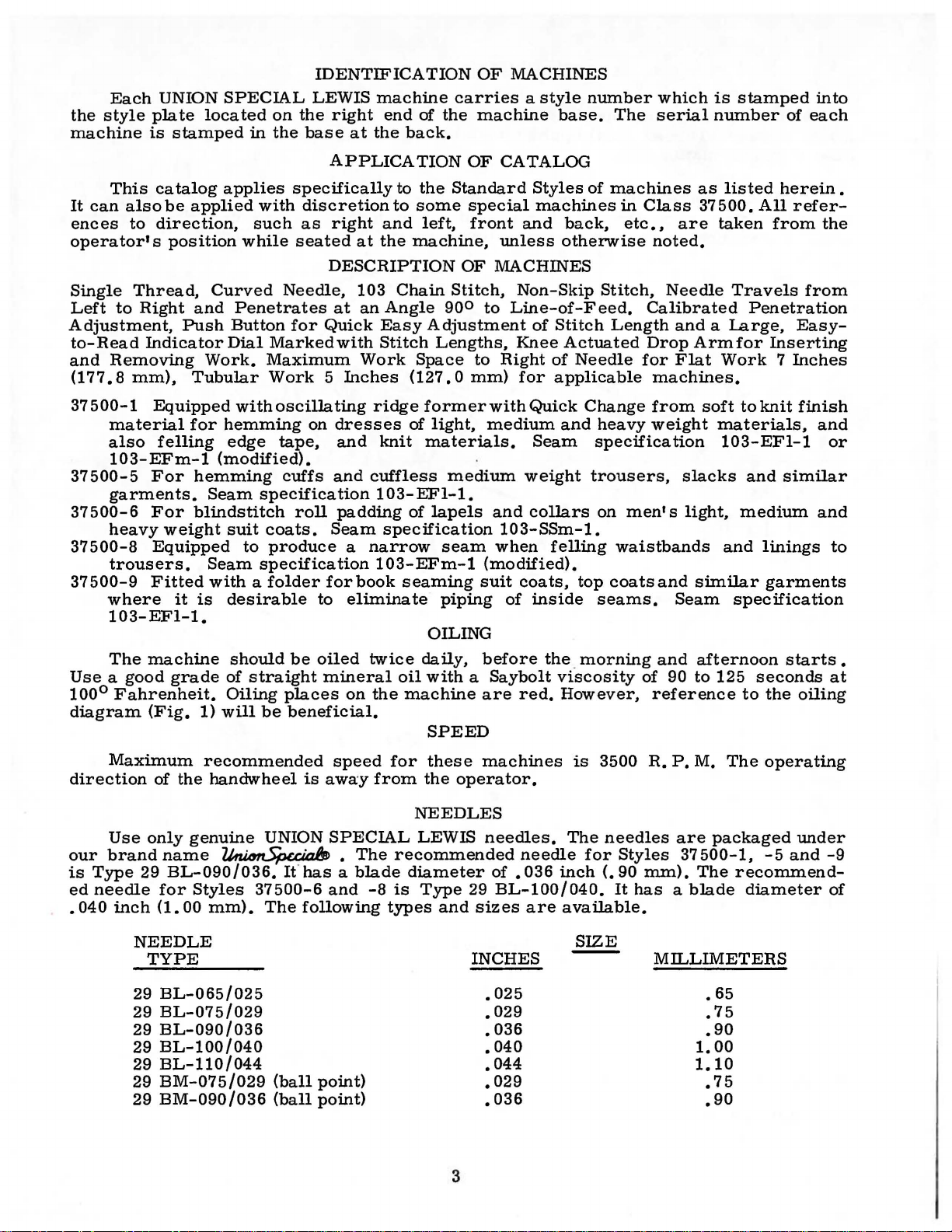
The
machine
Use a good
100°
Fahrenheit.
diagram
(Fig.
be
applied
position
Curved
and
Push
Work.
Tubular
for
hemming
Seam
blindstitch
weight
Seam
with a folder
it
is
grade
1)
applies
while
specifically
with
such
seated
discretion
as
Needle,
Penetrates
Button
Dial
for
Marked
Maximum
Work 5 Inches
withoscillating
hemming
edge
tape,
(modified).
cuffs
specification
roll
suit
coats.
to
produce
specification
desirable
should
of
Oiling
will
be
straight
places
be
beneficial.
APPLICATION
to
to
right
at
and
the
DESCRIPTION
103
Chain
at
an
Angle
Quick
with
Easy
Stitch
Work
ridge
on
dresses
and
knit
and
cuffless
103-EFl-1.
padding
Seam
specification
a
narrow
103-EFm-1
forbook
to
eliminate
oiled
mineral
on
seaming
twice
oil
the
OF
CATALOG
the
Standard
some
machine,
left,
special
front
unless
OF
MACHINES
Stitch,
900
to
Adjustment
Lengths,
Space
to
Right
(127. 0 mm)
formerwithQuick
of
light,
medium
materials.
medium
of
lapels
and
103-SSm-1.
seam
when
(modified).
suit
piping
of
OILING
daily,
before
with a Saybolt
machine
are
SPEED
Styles
of
machines
machines
and
back,
otherwise
Non-Skip
Stitch,
Line-of-Feed.
of
Stitch
Knee
of
for
applicable
Actuated
Needle
Change
and
heavy
Seam
weight
collars
specification
trousers,
on
felling
coats,
inside
top
seams.
coats
the. morning
viscosity
red.
However,
in
Class
etc.,
are
noted.
Needle
Calibrated
Length
and a Large,
Drop
for
Flat
machines.
from
weight
slacks
men's
waistbands
and
Seam
and
of
90
reference
as
listed
37
500.
All
taken
Travels
Penetration
Armfor
Work 7 Inches
soft
to
knit
materials,
103-EFl-1
and
light,
medium
and
linings
similar
specification
afternoon
to
125
seconds
to
herein
refer-
from
the
from
Easy-
Inserting
finish
and
similar
and
garments
starts
the
oiling
.
or
to
•
at
Maximum
direction
Use
our
brand
is
Type
ed
needle
• 040
inch
of
the
only
genuine
name
29
BL-090/036.
for
Styles
(1.
00
NEEDLE
TYPE
29
BL-065/025
29
BL-075/029
29
BL-090/036
29
BL-100/040
29
BL-110/044
29
BM-075/029
29
BM-090/036
recommended
handwheel
UNION
~
If
has a blade
37500-6
mm).
The
following
(ball
(ball
speed
is
awa:y
SPECIAL
•
and
point)
point)
for
from
NEEDLES
The
recommended
diameter
-8
is
types
these
the
operator.
LEWIS
Type
and
3
machines
needles.
needle
of
.036
29
BL-100/040.
sizes
are
INCHES
• 025
• 029
• 036
• 040
• 044
• 029
.036
is
3500
The
needles
for
Styles
inch(.
90
It
available.
SIZE
R.
P.M.
are
The
packaged
37500-1,
mm).
The
has a blade
MILLIMETERS
• 65
.75
.90
1.
00
1.10
.75
.90
operating
under
-5
and
recommend-
diameter
-9
of
Page 4
NEEDLES
(Continued)
Selection
material
good
sample
label.
stitch
To
used.
have
needle,
A
complete
of
proper
Thread
formation.
needle
or
the
order
needle
should
orders
Type
would
size
pass
promptly
number
read:
is
determined
freely
and
should
"100
through
accurately
be
forwarded.
Needles,
by
size
needle
filled,
Type
of
eye
Use
29
thread
in
order
an
empty
the
description
BL-090
and
to
produce
package,
/036".
weight
on
of
a
a
the
When
far
as
it
Immediately
improper
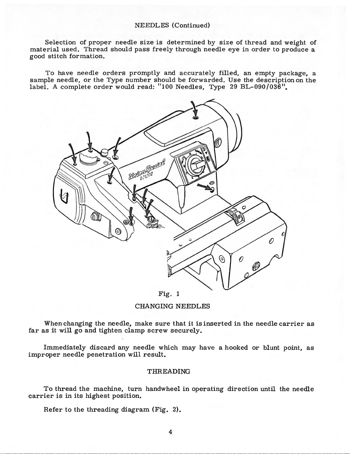
To
carrier
Refer
changing
will
needle
thread
is
in
to
go
and
discard
penetration
the
machine,
its
highest
the
threading
the
needle,
tighten
CHANGING
make
clamp
any
needle
will
turn
position.
diagram
Fig.
sure
screw
which
result.
THREADING
handwheel
(Fig.
1
NEEDLES
that
it
securely.
may
in
2).
4
is
inserted
have a hooked
operating
in
the
direction
needle
or
blunt
until
carrier
point,
the
needle
as
as
Page 5
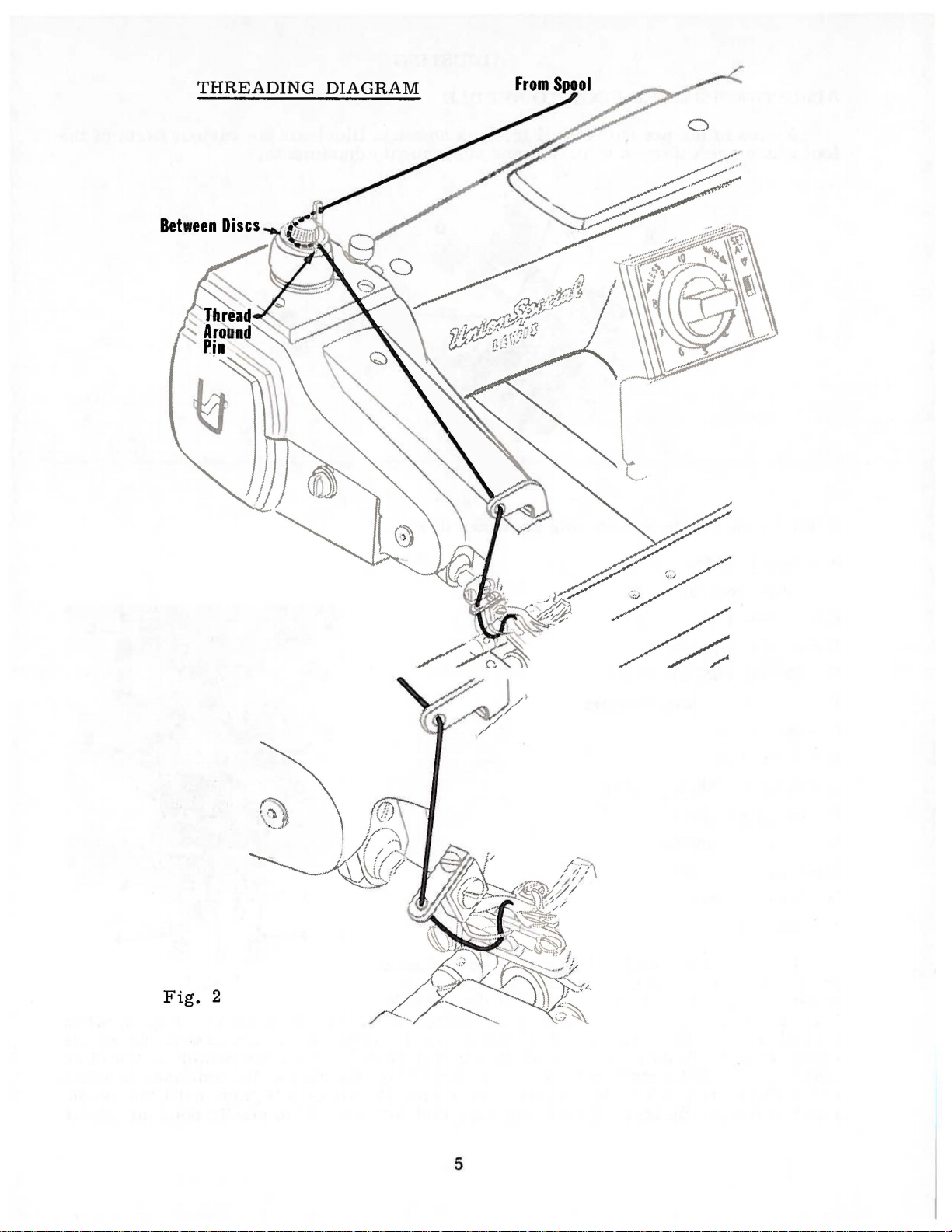
THREADING
DIAGRAM
Fig.
2
5
Page 6
ADJUSTING
ADJUSTING
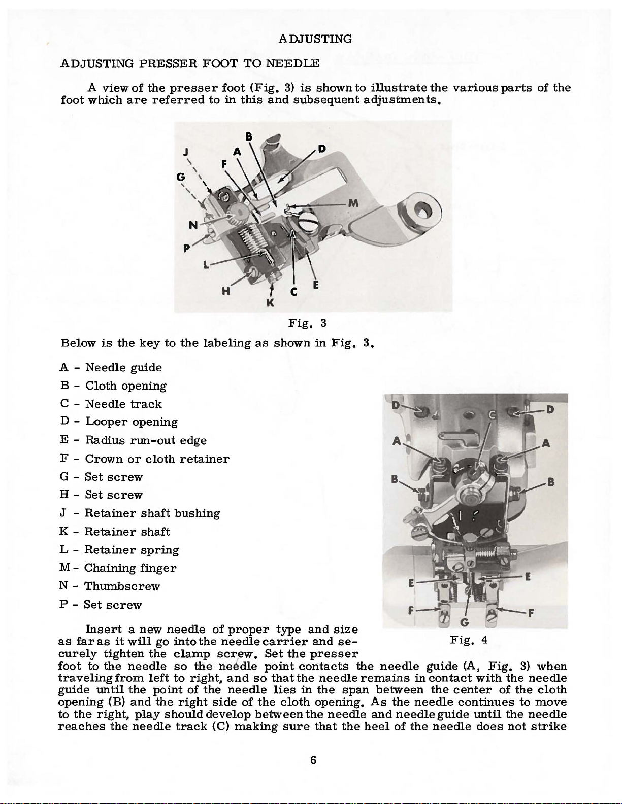
A
view
foot
which
Below
is
are
the
PRESSER
of
the
presser
referred
key
to
the
FOOT
foot
to
in
this
labeling
TO
NEEDLE
(Fig.
and
K
as
3)
is
subsequent
Fig.
shown
shown
3
in
Fig.
to
illustrate
adjustments.
3.
the
various
parts
of
the
A -
Needle
B -
Cloth
C -
Needle
D -
Looper
E -
Radius
F -
Crown
G-
Set
H-
Set
J -
Retainer
K -
Retainer
L -
Retainer
M-
Chaining
N -
Thumbscrew
P-
Set
Insert a new
as
far
as
curely
foot
to
the
traveling
guide
until
opening
to
the
right.
reaches
guide
opening
track
opening
run-out
or
screw
screw
screw
it
will
tighten
needle
from
the
(B)
and
play
the
needle
cloth
shaft
shaft
spring
finger
needle
go
the
left
point
the
should
edge
retainer
bushing
into
the
clamp
so
the
to
right.
of
the
right
develop
track
of
proper
needle
screw.
ne~dle
and
carrier
Set
point
so
needle
side
of
the
between
(C)
making
type
the
that
lies
cloth
sure
and
size
and
presser
contacts
the
needle
in
the
opening.
the
needle
that
se-
span
the
the
needle
remains
between
As
and
heel
in
the
needle
needle
of
the
Fig.
guide
contact
the
center
continues
guide
needle
(A.
until
4
Fig.
with
does
the
of
the
3)
the
to
not
when
needle
cloth
move
needle
strike
6
Page 7
the
needle
farther
top
ofthe
the
upper
these
equally, a little
on
the
be
attempted.
guide
to
the
presserfootbrackets,
screws
screws
sides
(B)
have
ADJUSTING
(A,
Fig.
3)
right.
To
accomplish
(B)
on
the
just
enough
at a time,
been
tightened,
PRESSER
and
lift
off
these
so
that
side
to
to
hold
obtain
no
of
FOOT
the
the
each
the
the
further
TO
needle
adjustments,
heads
bracket,
presser
aforementioned
adjustment
NEEDLE
track
donot
(C)
loosen
contactthe
move
foot
up.
of
(Continued)
while
presser
Adjust
settings.
the
advancing
screws
foot
the
top
screws
(A,
washers.
up,
top
screws
After
screws
the
needle
Fig.
(A)
4)
Loosen
retighten
should
on
(A)
(B)
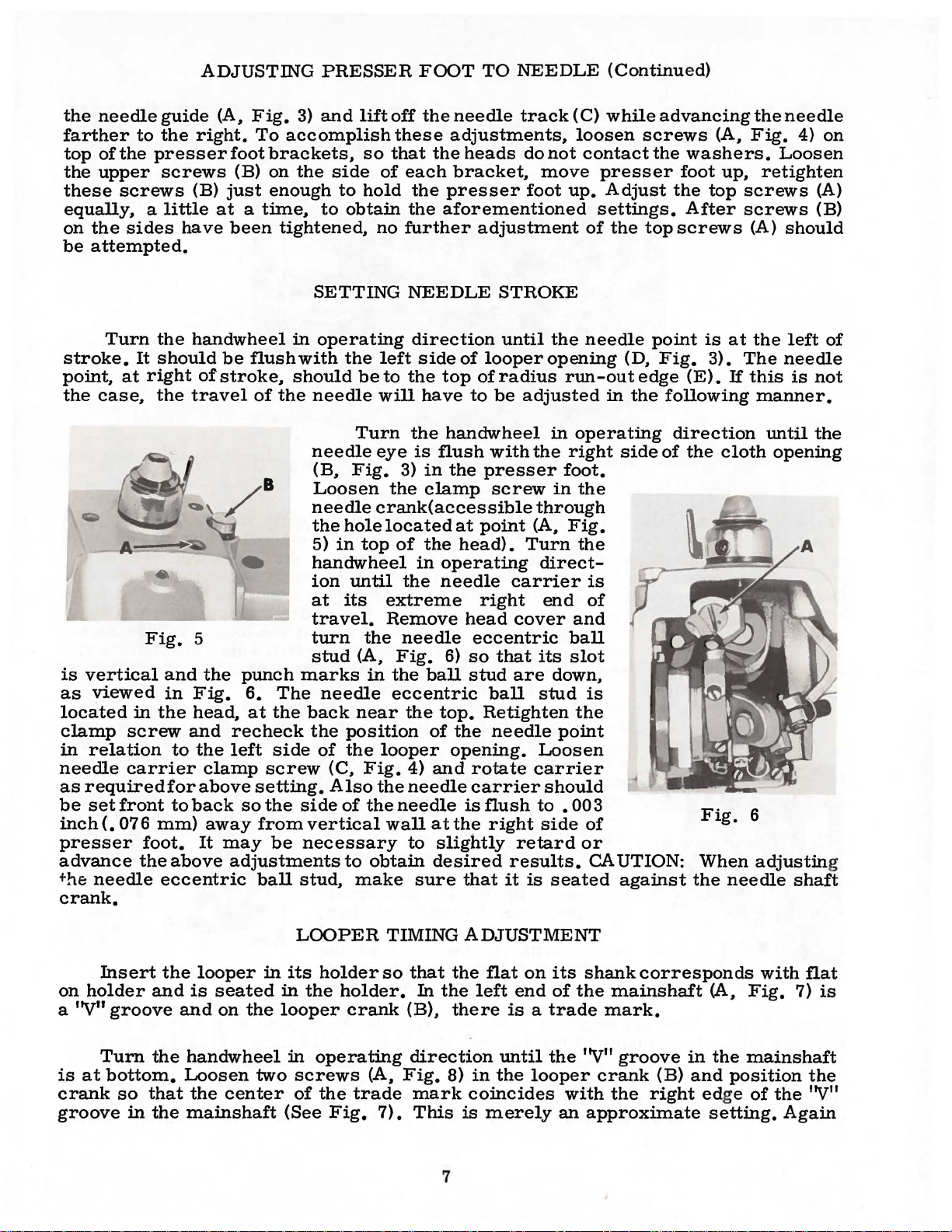
Turn
stroke.
point,
the
case,
is
vertical
as
viewed
located
clamp
in
relation
needle
as
required
be
set
front
inch
(.
07 6
presser
advance
the
needle
crank.
the
It
should
at
right
the
Fig.
and
in
in
the
screw
carrier
mm)
foot.
the
eccentric
handwheel
be
ofstroke,
travel
5
the
Fig.
head,
and
to
the
clamp
for
above
to
back
away
It
may
above
SETTING
in
operating
flushwith
should
of
the
needle
needle
(B,
Loosen
needle
the
5)
handwheel
ion
at
travel.
turn
stud
punch
6.
at
recheck
left
so
adjustments
marks
The
the
back
the
side
screw
setting.
the
side
from
ball
vertical
be
necessary
stud,
needle
of
the
be
Turn
Fig.
hole
in
top
until
its
the
(A,
in
near
position
the
(C,
Fig.
Also
of
the
to
obtain
make
NEEDLE
direction
left
side
to
the
top
will
have
the
handwheel
eye
is
flush
3)
in
the
the
clamp
crank(accessible
located
of
the
in
operating
the
needle
extreme
Remove
needle
Fig.
the
eccentric
looper
the
needle
wall
6)
ball
the
top.
of
4)
and
needle
at
to
slightly
desired
sure
opening.
STROKE
until
of
looperopening
ofradius
to
be
with
presser
screw
at
point
head).
right
head
eccentric
so
that
stud
ball
Retighten
the
needle
rotate
carrier
is
flush
the
right
that
it
the
adjusted
in
the
in
through
(A,
Turn
direct-
carrier
end
cover
its
are
down,
stud
point
Loosen
carrier
should
to
• 00 3
side
retard
results.
is
seated
needle
(D,
run-out
in
operating
right
foot.
Fig.
and
ball
slot
side
the
the
is
of
is
the
of
or
CAUTION:
against
point
Fig.
edge
the
following
of
is
at
3).
(E).
If
direction
the
cloth
Fig·
When
the
needle
the
left
The
needle
this
manner.
until
opening
6
adjustin
is
not
the
shaft
of
g
Insert
on
holder
a "V"
Turn
is
at
bottom.
crank
groove
and
groove
the
so
that
in
the
the
looper
is
seated
and
on
handwheel
Loosen
the
mainshaft
in
the
two
center
LOOPER
its
holder
in
the
looper
in
operating
screws
of
the
(See
Fig.
TIMING
so
holder.
crank
(A,
trade
7).
that
the
In
the
(B),
there
direction
Fig.
8)
mark
This
is
7
ADJUSTMENT
flat
on
its
left
end
of
is a trade
until
in
the
coincides
merely
the
looper
an
shank
the
''V"
with
approximate
corresponds
mainshaft
mark.
groove
crank
the
(A,
in
the
(B)
and
position
right edge
setting.
with
flat
Fig.
7)
is
mainshaft
the
of
the
''V"
Again
Page 8
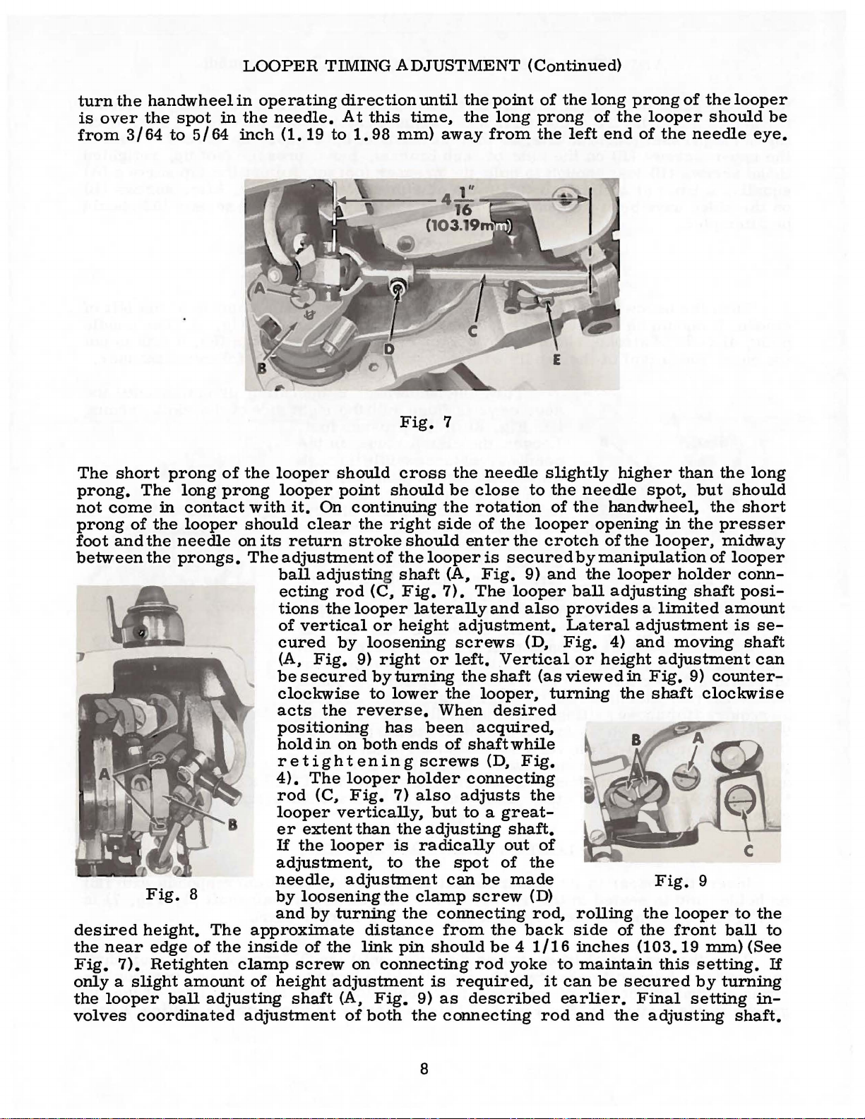
turn
is
over
from
the
handwheel
the
3/64
spot
to
5/64
LOOPER
in
operating
in
the
inch
needle.
(1.19
TIMING
direction
At
this
to
1.
98
ADJUSTMENT
until
time,
mm)
the
the
away
point
long
from
(Continued)
of
the
long
prong
the
left
of
end
prong
the
looper
of
the
of
the
should
needle
looper
be
eye.
The
short
prong.
not
prong
foot
between
The
come
of
and
in
the
the
the
Fig.
desired
the
Fig.
near
7).
height.
edge
Retighten
only a slight
the
looper
volves
coordinated
prong
long
contact
looper
needle
prongs.
8
of
amount
ball
adjusting
of
the
prong
with
should
on
The
The
approximate
the
inside
clamp
of
adjustment
looper
looper
it.
On
clear
its
return
adjustment
ball
adjusting shaft
ecting
tions
of
the
vertical
cured
(A,
Fig.
be
secured
clockwise
acts
the
positioning
hold
in
retightening
4).
The
rod
(C,
looper
er
extent
If
the
adjustment,
needle,
by
loosening
and
by
of
the
screw
height
shaft
Fig.
should
point
cross
should
continuing
the
right
stroke
rod
of
(C,
should
the
Fig.
looper
or
height
by
loosening
9)
right
by
turning
to
lower
reverse.
has
on
both
ends
looper
Fig.
7)
vertically,
than
the
looper
is
to
adjustment
the
turning
the
distance
link
pin
on
connecting
adjustment
(A,
Fig.
of
both
7
the
be
the
side
looper
(A,
7).
laterally
screws
or
left.
the
When
been
of
screws
holder
also
but
adjusting
radically
the
spot
can
clamp
connecting
from
should
is
required,
9)
as
the
connecting
needle
close
to
rotation
of
the
looper
enter
is
Fig.
The
and
the
secured
9)
looper
also
adjustment.
(D,
Vertical
the
shaft
(as
looper,
desired
acquired,
shaft
(D,
while
Fig.
connecting
adjusts
the
to a great-
shaft.
out
of
of
the
be
made
screw
(D)
rod,
the
back
be 4 1/16
rod
yoke
described
slightly
the
of
the
higher
needle
handwheel,
spot,
opening
crotch
and
of
the
by
manipulation
the
looper
ball
adjusting
looper,
provides a limited
Lateral
Fig.
or
viewed
turning
adjustment
4)
and
height
in
the
Fig.
shaft
Fig.
to
it
can
earlier.
rod
rolling
side
inches
maintain
be
and
the
of
the
(103.19
secured
Final
the
adjusting
than
but
the
should
the
in
the
presser
midway
of
looper
holder
shaft
amount
moving
adjustment
9)
counter-
clockwise
9
looper
front
ball
mm)
this
setting.
by
turning
setting
long
short
conn-
posi-
is
se-
shaft
can
to
the
to
(See
If
in-
shaft.
8
Page 9
stud
marks
as
required,
down
Fig.
in
10
retighten
stud
to
SETTING
feed
needle
feed
needle.
mately
stud
way
tor.
screws
The
when
tor
stud
stud,
clamp
obtain a full
As
dog
is
dog
Feed
the
should
toward
The
slot
the
and
the
should
loosen
screw.
tooth
THE
the
needle
should
flush
is
3/32,:!:
depth
operator.
feed
(B,
in
eccentric
feed
punch
It
depth
FEED
contact
with
dog
should
be
horizontal
dog
Fig.
bar
be
towards
clamp
may
for
DOO
travels
the
right
1/32
of a full
9)
is
marks
be
inch(2.
depress
Dots
is
adjusted
on
the
stud
all
the
at
the
screw
necessary
shorter
from
feed
side
38,:!:.
tooth.
when
should
right
(C)
should
way
the
end
operator.
(E.
number
right
plates
of
cloth
feed
plates
Slot
feed
be
by
side
towards
of
Fig.
to
7)
rotate
of
to
left,
when
opening
79
mm)behind
approxi-
in
eccentric
bar
is
toward
means
of
the
be
horizontal
the
the
slot
To
position
and
position
the
stitches.
point
all
opera-
of
head.
opera-
in
punch
the
of
and
the
two
the
CAUTION:
looper
end
of
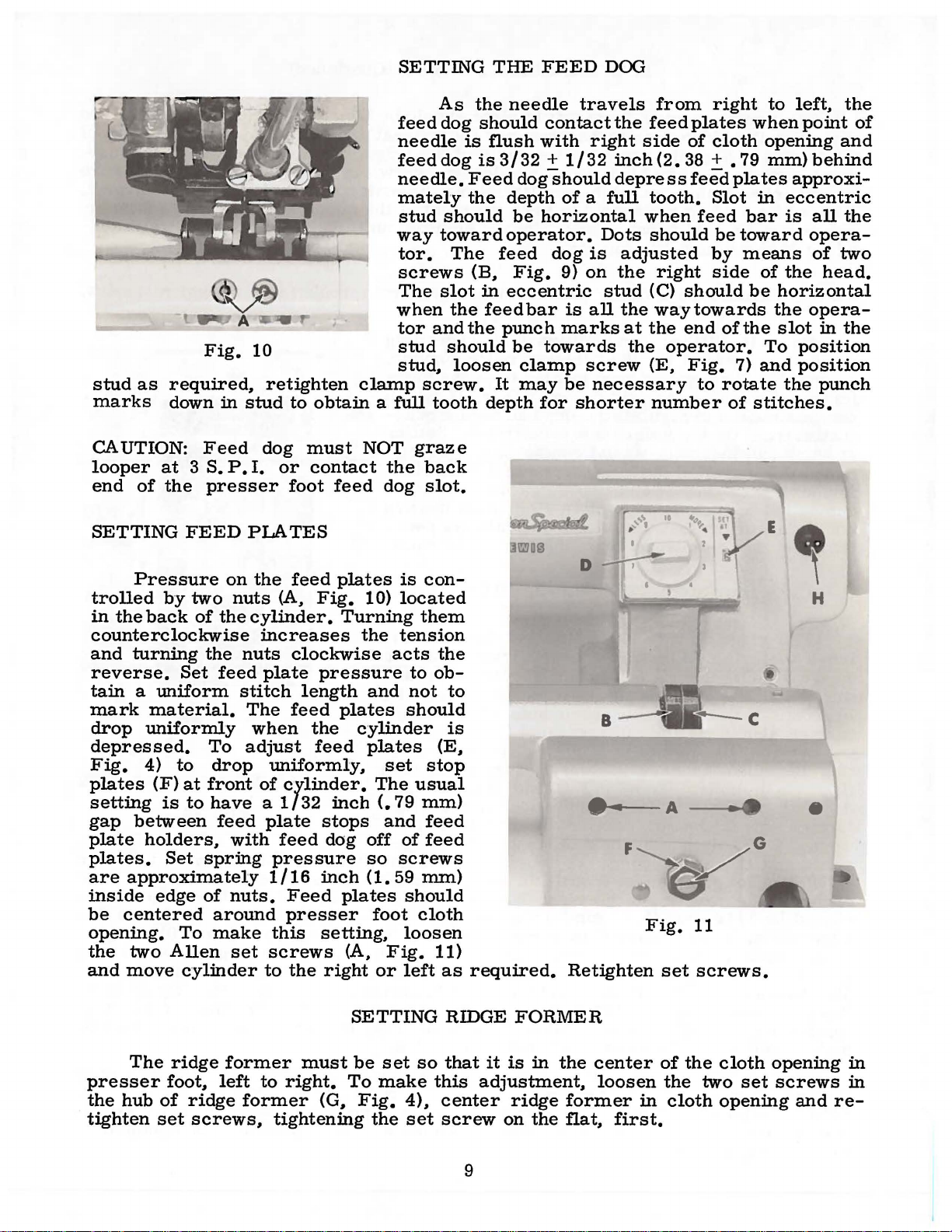
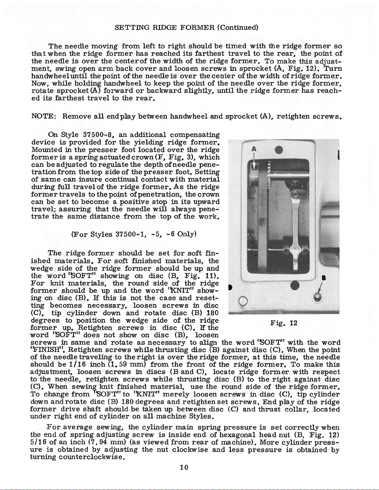
SETTING
Pressure
trolled
in
the
back
counterclockwise
and
turning
reverse.
tain a uniform
mark
drop
depressed.
Fig.
plates
setting
gap
plate
plates.
are
inside
be
opening.
the
and
material.
uniformly
4)
(F)
between
holders
approximately
edge
centered
two
move
Feed
at 3 S.
the
presser
FEED
by
two
of
the
Set
To
to
drop
at
front
is
to
have a 1/32
..
Set
spring
of
around
To
make
Allen
cylinder
the
feed
feed
dog
P.
I.
PLATES
on
the
nuts
cylinder.
increases
nuts
plate
stitch
The
when
adjust
uniformly,
of
plate
with
1/16
nuts.
set
screws
to
must
or
contact
foot
feed
feed
(A,
Fig.
clockwise
pressure
length
feed
the
feed
cylinder.
inch
stops
feed
dog
pressure
inch
Feed
presser
this
the
setting,
right
NOT
the
dog
plates
10)
Turning
the
acts
and
plates
cylinder
plates
set
The
(.
and
off
so
(1.
plates
foot
(A,
Fig.
or
graze
back
slot.
is
con-
located
them
tension
the
to
ob-
not
should
(E
stop
usual
79
mm)
feed
of
feed
screws
59
mm)
should
cloth
loosen
11)
left
as
to
is
..
required.
D
...
F
Retighten
A
Fig.
set
E
H
•
11
screws.
The
presser
the
hub
tighten
ridge
foot..
of
set
former
left
ridge
screws,
to
right.
former
tightening
must
(G
SETTING
be
set
To
make
..
Fig.
the
so
4),
set
RIDGE
that
this
center
screw
9
FORMER
it
is
in
the
adjustment,
ridge
on
the
center
loosen
former
flat,
in
first.
of
the
the
cloth
cloth
two
set
opening
opening
screws
andre-
in
in
Page 10
The
that
when
the
needle
ment,
swing
handwheel
Now~
rotate
ed
while
its
sprocket
farthest
needle
the
ridge
is
over
open
until
holding
moving
the
arm
the
point
handwheel
(A)
forward
travel
SETTING
from
former
centerof
back
of
to
the
left
has
cover
the
or
rear.
needle
to
RIDGE
to
right
reached
the
width
and
loosen
is
keep
the
backward
FORMER
should
its
farthest
of
the
(Continued)
be
timed
ridge
screws
over
the
center
point
slightly~
of
the
until
travel
former.
in
sprocket
of
the
needle
the
with
to
the
width
over
ridge
the
rear~
To
make
(A,
the
former
ridge
Fig.
of
ridge
ridge
former
the
this
12).
former.
former,
has
point
adjust-
Turn
reach-
so
of
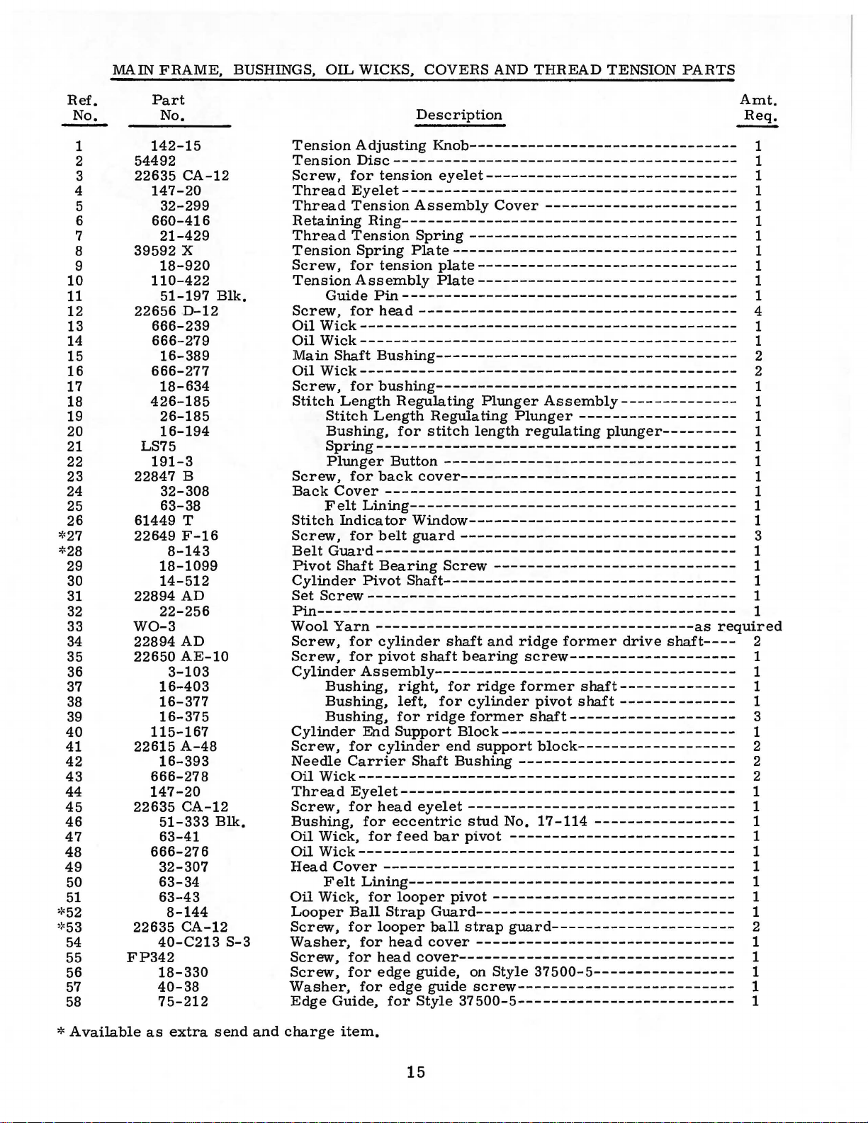
NOTE:
device
Mounted
former
can
tration
of
same
during
former
can
travel;
trate
ished
wedge
the
For
former
ing
ting
(C)~
degrees
former
word
screws
Remove
On
Style
is
in
is a spring
be
adjusted
from
can
full
travels
be
set
assuring
the
The
ridge
materials.
side
word
knit
should
on
disc
becomes
tip
to
up.
''SOFT"
in
''FINISH".
of
the
needle
should
be
adjustment.
to
the
needle,
(C).
When
To
change
down
former
under
and
right
rotate
drive
all
end
37500-8~
provided
the
for
presser
actuated
to
regulate
the
top
side
insure
travel
to
become a positive
same
(For
continual
of
the
to
the
point
that
distance
Styles
the
37500-1~
former
For
soft
of
the
ridge
''SOFT"
mater:ials,
(B).
showing
be
up
If
this
the
and
necessary,
cylinder
position
down
the
Retighten
does
same
Retighten
traveling
1/16
loosen
and
inch
not
rotate
screws
to
(1.
screws
retighten
sewin~
from
end
'SOFT"
disc
shaft
of
knit
(B) 180
should
cylinder
play
between
an
additional
the
yielding
foot
located
crown
the
of
the
contact
ridge
of
penetration~
needle
from
should
finished
former
on
round
the
is
not
loosen
and
wedge
screws
show
on
as
while
the
right
59
mm)
in
screws
finished
to
''KNIT"
degrees
be
on
(F~
depth
ofneedle
presser
former.
stop
will
the
top
-5~
be
set
materials~
should
disc
side
word
the
case
screws
rotate
side
in
disc
disc
necessary
thrusting
is
from
discs
while
material,
merely
taken
all
up
machine
handwheel
compensating
ridge
over
Fig.
former.
the
ridge
3),
which
pene-
foot.
with
As
in
always
of
-6
for
(B~
of
''KNIT"
disc
of
(B).
material
the
the
its
upward
the
Only)
soft
be
Fig.
the
and
in
(B) 180
the
(C).
to
Setting
ridge
crown
pene-
work.
fin-
up
11).
ridge
show-
reset-
disc
ridge
If
loosen
align
disc
over
the
the
front
(Band
ridge
C),
thrusting
use
loosen
and
retighten
between
Styles.
and
the
and
the
(B)
of
locate
disc
the
disc
sprocket
t
the
against
former,
the
ridge
(B)
round
screws
set
screws.
(C)
Q
word
ridge
to
side
in
and
(A)~
Fig.
''SOFT"
disc
(C).
at
this
former.
former
the
of
disc
End
thrust
retighten
1
2
with
When
time,
To
with
right
the
against
ridge
(C),
play
collar,
the
the
the
make
tip
cylinder
of
the
screws.
I
word
point
needle
this
respect
disc
former.
ridge
located
For
the
end
5/16
ure
of
is
turning
average
of
spring
an
inch
obtained
counterclockwise.
sewing,
adjusting
(7.
94
by
adjusting
mm)
the
screw
(as
cylinder
is
viewed
the
nut
main
inside
from
end
rear
clockwise
spring
of
of
and
pressure
hexagonal
machine).
10
less
is
set
head
More
pressure
correctly
nut
(B,
cylinder
is
obtained
Fig.
press-
when
12)
by
Page 11

On
Styles
all
machine
former
enough
penetration
(E).
The
needle
cylinder
and
hexagonal
end
of
machine
1/2
turn.
37500-1.
Styles.
to
note
dial
(D.
graze
turning
nut.
Remove
below
Retighten
-5.
At
maximum
the
Fig.
setting
screw
all
the
handwheel.
nut.
SETTING
-6
rotate
needle
11)
should
is
made
(G)
as
free
play
NOTE:
NEEDLE
disc
penetration
lifting
be
set
by
required
in
knee
after
Recheck
GRAZE
to
soft
finish.
the
off
of
the
at
"1
0 ".
loosening
to
get
the
press
loosening
''NEEDLE
then
needle
needle
with
"6'
hexagonal
proper
with
the
stop
nut.
GRAZE
proceed
should
~ide.
graze
At
showing
nut
(F)
needle
screw
then
graze.
located
back
SETTING".
as
follows
this
in
the
at
the
off
for
the
ridge
time
the
window
front
Retighten
on
right
the
screw
of
and
be
screw
right
an
eccentric.
Press
The
as
(G
as
the
Fig.
crown
or
close
and
H.
required.
to
shaft
to
13
cloth
to
the
Fig.
3)
Tighten
position
the
left
retainer
needle
and
the
against
as
adjust
screw
crown
CHANGING
holding
ting
felt
Continuing
in
operating
length
the
on
the
(F.
Fig.
possible.
the
shaft
(G)
against
or
retainer
the
bushing
Press
plunger
direction
to
drop
and
stitch
Stitch
the
indicator
window
3)
should
To
adjust
bushing
bushing
and
THE
plunger
until
into
to
hold
direction
in
opposite
length.
lengths
(H.
Fig.
FURTHER
(For
Styles
be
crown
as
close
tighten
STITCH
(B.
Fig.
in.
turn
stitch
the
slot
the
plunger
are
indicated
dial
and
11).
ADJUSTMENTS
37
centered
or
(J)
and
(J).
Turn
as
set
LENGTH
5)
handwheel
regulating
of
in.
to
increase
direction
are
in
the
500-1.
over
retainer.
shaft
(K)
shaft
possible
screw
in
firmly.
feed
turn
to
by
graduations
viewed
belt
-5.
-6.
ridge
to
(K)
to
the
(H).
While
in
opera-
finger
is
regulator.
handwheel
the
stitch
decrease
through
guard.
-8)
former
loosen
the
which
left
set
or
is
needle.
Normal
(L.
Fig.
taken
of
finger
the
On
from
right
(M.
stitch.
on
top
of
of
the
crown
to
the
adjusting
rating
loose.
On
possible.
Folder
of
folder
be
assembled
using
can
obtain
ly.,
clamp
be
accomplished
desired
adjust
crown
3)
rests
this
presser
Fig.
Style
A
finer
the
37500-8.
crown
with a nylon
Style
37500-9.
with
must
also
are
available
on
on
results
thumbscrew
or
cloth
in
the
position
foot
3)
should
adjustment
of
the
thumbscrew
the
the
ridge
be
positioned
to
the
top
top
or
bottom
by
and
(D).
retainer
''Vee"
and
on
moved
boss.
be
set
the
penetration
can
be
presser
plug
behind
through
folder
former
to
suit
the
of
bottom
of
same.
loosening
retighten
spring
top
to
for
additional
as
close
of
pressure
the
the
as
dial
made
foot.
(A.
by
There
it.
Tightening
the
nylon
Fig.
13)
positioned
clear
path
convenience
of
bracket
Moving
the
screw
screw.
To
11
is
when
right
''Vee'~
presser
located
tension.
possible
should
adjusting
is
to
be
the
also a set
this
plug
should
to
present
of
of
(C)
the
in
raise
which
be
looper.
the
operator.
or
the
folder
clamp
or
lower
the
foot
to
the
if
required.
the
needle.
set
so
thumbscrew
screw
set
screw
prevents
set
as
close
raw
edge
Four
settings
bracket
laterally
(B).
position
the
right
boss.
rear
as
to
applies
of
Folder
can
or
entire
leg
of
the
spring
The
leg
can
near
The
the
chaining
obtain a blind
(N.
Fig.
(P)
at
the
pressure
same
to
hem
be
tipping
the
to
for
clamp
turned
as
required
folder
from
needle
needle.
the
height
(B)
over.
its
slight-
be
top
3)
front
vib-
as
can
nose
to
Page 12

TERMS
Prices
forwarded
wise
directed.
Torque
a
distance
driver,
amount
unless
hand
etc.
of
All
straps
otherwise
as
tightly
The
are
f.
o.
b.
A
(measured
by a lever
Many
torque
and
as
screws
net
cash
shipping
charge
of
will
eccentrics
noted.
possible,
and
point.
is
made
TORQUE
in
inch-pounds)
(in
inches
these
tighten
All
other
unless
subject
Parcel
to
or
devices
the
part
should
nuts,
requiring a specific
to
change
post
cover
REQUIREMENTS
shipments
postage
is a rotating
feet).
otherwise
This
are
available,
to
the
be
tightened
bolts,
torque,
is
correct
screws,
noted.
will
without
notice.
are
and
insurance.
force
(in
accomplished
which
when
amount
to
19-21
inch-pounds
etc.,
be
indicated
All
insured
pounds)
applied
by a wrench,
set
and
no
tighter.
should
on
the
be
picture
shipments
unless
other-
through
at
the
proper
(22-24
em/kg)
tightened
plates.
are
screw
by
12
Page 13

EXPLODED
AND
VIEWS
DESCRIPTION
SINGLE
BLINDSTITCH
NON-
FOR
CLASS
THREAD
SKIP
OF
PARTS
37
500
CHAINSTITCH
MACHINES
STITCH
13
Page 14

27
l
'
28
14
Page 15
MAIN
FRAME,
BUSHINGS,
OIL
WICKS,
COVERS
AND
THREAD
TENSION
PARTS
Ref.
No.
1
2
3
4
5
6
7
8
9
10
11
12
13
14
15
16
17
18
19
20
21
22
23
24
25
26
:0:<27
*28
29
30
31
32
33
34
35
36
37
38
39
40
41
42
43
44
45
46
47
48
49
50
51
·~52
·~53
54
55
56
57
58
Part
No.
142-15
54492
22635
147-20
32-299
660-416
21-429
39592
18-920
110-422
51-197
22656
666-239
666-279
16-389
666-277
18-634
426-185
26-185
16-194
LS75
191-3
22847 B
32-308
63-38
61449 T
22649
8-143
18-1099
14-512
22894
22-256
W0-3
22894
22650
3-103
16-403
16-377
16-375
115-167
22615
16-393
666-278
147-20
22635
51-333
63-41
666-276
32-307
63-34
63-43
8-144
22635
40-C213
FP342
18-330
40-38
75-212
CA-12
X
Elk.
D-12
F-16
AD
AD
AE-10
A-48
CA-12
Elk.
CA-12
S-3
Description
Tension
Tension
Screw,
Thread
Thread
Retaining
Thread
Tension
Screw,
Tension
Screw,
Oil
Oil
Main
Oil
Screw,
Stitch
Adjusting
Knob--------------------------------
Disc-----------------------------------------
for
tension
eyelet------------------------------
Eyelet----------------------------------------
Tension
Assembly
Cover
-----------------------
Ring----------------------------------------
Tension
Spring
for
Assembly
Guide
for
Pin----------------------------------------
Spring
--------------------------------
Plate----------------------------------
tension
plate-------------------------------
Plate-------------------------------
head-------------------------------------Wick--------------------------------------------Wick---------------------------------------------
Shaft
Bushing------------------------------------
Wick---------------------------------------------
for
bushing------------------------------------
Length
Stitch
Bushing,
Regulating
Length
for
Plunger
Regulating
stitch
length
Assembly--------------
Plunger
-------------------
regulating
plunger---------
Spring-------------------------------------------
Plunger
Screw,
Back
Cover
Felt
Stitch
Indicator
Screw,
Belt
Guard-------------------------------------------
Pivot
Shaft
Cylinder
Set
Screw--------------------------------------------
Button
for
back
------------------------------------------
Lining---------------------------------------
-----------------------------------
cover---------------------------------
Window--------------------------------
for
belt
guard---------------------------------
Bearing
Pivot
Screw
-----------------------------
Shaft-----------------------------------
Pin-------------------------------------------------Wool
Screw,
Screw,
Yarn
--------------------------------------as
for
for
cylinder
pivot
shaft
shaft
bearing
and
ridge
former
screw--------------------
CylinderAssembly------------------------------------
Bushing,
Bushing,
Bushing,
Cylinder
Screw,
Needle
Oil
Thread
Screw,
for
Carrier
Wick---------------------------------------------
Eyelet----------------------------------------
for
Bushing,
Oil
Wick,
Oil
Wick---------------------------------------------
Head
Cover------------------------------------------
Felt
Oil
Wick,
Looper
Screw,
Ball
for
Washer,
Screw,
Screw,
for
for
Washer,
Edge
Guide,
End
Support
cylinder
head
for
eccentric
for
right,
left,
for
feed
for
for
ridge
ridge
cylinder
former
former
pivot
shaft--------------
shaft--------------
shaft--------------------
Block----------------------------
end
Shaft
support
Bushing
block-------------------
--------------------------
eyelet--------------------------------
stud
No.
bar
pivot
17-114
---------------------------
-----------------
Lining---------------------------------------
for
looper
for
head
edge
for
looper
Strap
head
edge
for
pivot
----------------------------Guard------------------------------ball
strap
cover
guard----------------------
------------------------------cover--------------------------------guide,
guide
Style
on
Style
37500-5-----------------
screw--------------------------
37500-5--------------------------
drive
shaft----
Amt.
~
1
1
1
1
1
1
1
1
1
1
1
4
1
1
2
2
1
1
1
1
1
1
1
1
1
1
3
1
1
1
1
1
required
2
1
1
1
1
3
1
2
2
2
1
1
1
1
1
1
1
1
1
2
1
1
1
1
1
*Available
as
extra
send
and
charge
item.
15
Page 16

8~
I
16
35
Page 17
PRESSER
FEET,
FEED
PLATES
AND
FEED
PLATE
HOLDER
PARTS
Ref.
t
..
~
*
*
10
11
12
13
14
15
16
17
18
19
20
21
22
23
24
25
26
27
28
29
30
31
32
33
34
35
No.
1
2
3
4
5
6
7
8
9
Part
No.
18-307
22652
80266
50-300
18-1094
FP342
405-590
405-589
405-590-1
405-591
122-47
18-1107
137-154
137-155
137-156
21-446
14-532
1351
75-255
88
16-399
18-643
50-160
18-908
99-346
18-269
21-75
22560
22-324
18-628
20-129
42-30
18-644
24-333
24-334
1160
660-466
14-534
24-335
A-8
5-590
5-589
5-591
L
6-56
A
L
Screw,
Screw,
Washer,
Presser
Screw,
-5, -6,
Screw,
Presser
cloth
Presser
9/32
Presser
1/32
Presser
11/32
Feed
Presser
-5, -6,
Screw,
Feed
Screw,
Spring,
Screw,
Feed
Adjusting
Nut,
Feed
Screw,
Feed
Feed
Nut,
37500-9
Retaining
Feed
Feed
opening,
inch
inch
Dog
Presser
Presser
Presser
Chaining
Screw,
Retainer,
notch,
Retainer,
notch,
Retainer,
with
No.
Spring
Eccentric
Screw,
Edge
Set
Bushing,
Needle
Screw,
Plate
Plate
for
Plate
Plate,
Plate,
for
Plate
Plate,
Description
for
presser
for
presser
for
presser
Foot
Bracket,
for
presser
-8
---------------------------------------
for
presser
Foot
Assembly,
Foot
Assembly,
(1.14
Foot
Assembly,
(.
79
Foot
Assembly,
inch
(8.
No.
Foot,
Foot,
Foot,
Finger--------------------------------
for
for
for
5/64
405-591
---------------------------------------for
Guide------------------------------------
Screw,
for
Guide
for
Foot
Bracket,
-8
---------------------------------------
for
feed
Holder----------------------------------
for
feed
for
feed
for
feed
Holder
Screw,
feed
plate
Holder
for
feed
left,
right,
feed
plate
-----------------------------------------
Ring,
Shaft,
for
foot----------------------------foot
bracket
foot
bracket
left--------------------------
foot,
for
foot,
for
1/4
for
Styles
mm)
mm)
73
mm)
23-346
for
for
for
chainin~
marked'
Nos.
marked
No.
405-590-1----------------------
marked
inch
(1.98
---------------------------------
Retainer
edge
guide
for
bushing
retainer
----------------------------------
needle
plate,
plate
plate
plate
Hinge
for
feed
spring
Stop
pla~e
for
all
for
screw,
for
Style
for
Style
37500-1,
for
cloth
for
notched
for
cloth
-----------------------------
Nos.
No.
No.
finger
C",
405-589
"D'',
"E'', • 312
mm)
Shaft------------------------
--------------------------
shaft----------------------
guide-------------------------
right,
for
all
holder
holder
holder
Pin
plate
adjusting
-----------------------------
holder
Styles
all
Styles
for
37500-9
Style
37
37
500-9
--------------------screw--------------
Styles
Style
medium
opening------------------
fine
heavy
opening,
405-590
405-589
405-591
5/64
1/32
and
spring
------------------------
hinge
------------------------
stop
500-9
37500-9
inch
(6.
weight
retainer----------------
weight
---------------------inch
and
405-590
inch(.
inch
wide
shaft-----------------
for
Styles
Styles
pin----------------
holder
--------------------
except
except
all
Styles
--------------------
------------------
-----------------------
37
500-1,
-----------
35
mm)
-5
---------------
weight
Requires
and
------------------
------------------
(1.
79
(7.
notch,
except
------------------
spring
screw
37
material,
material,
material,
405-590-1
98
mm)
-----------
mm)
94
mm)
for
37500-1,
37500-9
---------
------------
500-9
37
500-9
except
wide
--------
-------
use
wide
wide,
of
---
---
Amt.
Req.
2
4
4
1
1
1
1
1
1
1
1
1
1
1
1
1
1
1
1
1
1
1
2
1
1
1
1
2
2
2
2
2
2
2
2
2
2
1
1
2
2
1
1
t
See
Page
*
Available
25
as
for
extra
presser
send
foot
and
for
other
charge
Styles
item,
can
of
machines.
be
used
on
17
Styles
37500-1
and
-5
only.
Page 18

19
TORQUE
19-21
in.
(22
-24
em/kg)
57
TO
lbs.
TORQUE
19-21
(22-24cm/k
in.
TO
lbs.
g)
18
Page 19

FEED,
LOOPER
AND
NEEDLE
DRIVING
PARTS
Ref.
~
1
2
3
4
5
6
7
8
9
10
11
12
13
14
15
16
17
18
19
20
21
22
23
24
25
·~25A
25B
*25C
*25D
*25E
26
27
28
29
30 22894 c
31
32
33
34
35
36
37
38
39
40
41
42
43
44
45
46
47 22894 u
48
49
50
51
52
53
54
55
56
57
58
59
60
Part
No.
61256 G
17-177
666-170
137-19
660-220
666-239
48-186
22652
447-140
22559 D
18-492
40-199
660-204
666-239
666-279
33-149
21-439
22-53
149-33
46-202
22652
17-150
17-114
18-732
23-343
23-342
23-340
23-341
23-346
45-478
22652
48-188
22652
22894 D
14-524
439-7
SB15
118-37
22652
87
147-21
18-1101
29
29
17-179
41332 J
61434 G
16-392
22652
79-41
4124-60
18-1100
63-39
36-16
22652
4118-36
1170 L
449-35
22652
115-166
22652
22651
22-8
A-8
A-8
A-16
A-8
A-6
u
BL-090/036
BL-100/040
A-8
A-8
A-6
A-8
AB-3
for
Amt.
~
1
1
1
1
2
1
1
2
1
4
1
1
1
1
1
1
1
1
1
1
1
1
1
2
1
1
1
1
1
1
1
1
1
1
1
1
1
1
2
1
1
1
1
1
1
1
1
1
1
1
1
1
1
1
3
1
1
1
1
1
1
1
1
1
1
1
Description
VVasher-------------------------------------------------------Stud,
for
looper
Oil
VVick---------------------------------------------------
Retainer---------------------------------------------------
"O"
Ring-------------------------------------------------------
Oil
VVick-------------------------------------------------------
Looper
Needle
Oil
Feed
Spring,
Pin,
Stitch
Feed
Stud,
Eccentric
Screw,
Feed
Feed
Feed
Feed
Feed
Feed
use
Feed
Crank,
Needle
Collar---------------------------------------------------------
Needle
Needle,
Needle
Loope;
Thrust
Thrust
Thrust
Screw--------------------------------------------------------Ball,
Looper
Looper-------------------------------------------------------Screw---------------------------------------------------------
Looper
Looper
Looper
Pin,
Driving
Screw-----------------------------------------------------
Drive
Screw,
Spot
Screw,
Fiber
"O"
Ring---------------------------------------------------
Oil
VVick---------------------------------------------------
VVick-------------------------------------------------------
Driving
for
for
stitch
Regulator------------------------------------------------
Driving
Screw-----------------------------------------------------
for
feed
for
Dog,
Dog,
Dog,
Styles--------------------------------------------------------
Dog,
Dog,
Dog,
with
presser
Driving
Screw-----------------------------------------------------
for
Screw----------------------------------------------------Set
Screw--------------------------------------------------
Spot
Screw-------------------------------------------------
Carrier
Screw-----------------------------------------------------
Carrier------------------------------------------------Clamp
Screw----------------------------------------------------Thread
Thumb
for
for
Ball
VVasher,
VVasher,
Bushing-------------------------------------------------
for
looper
Screw-------------~---------------------------------------
Ball
Screw----------------------------------------------------Oil
VVick---------------------------------------------------
Carrier
Screw-----------------------------------------------------
Carrier
Screw-----------------------------------------------------
Carrier
Clamp
Set
Screw--------------------------------------------------
for
looper
driving
Crank-------------------------------------------
Eccentric
for
connecting
for
VVasher
Lever
stitch
regulator
Lever
driving
Stud
-------------------------------------------------
feed
dog---------------------------------------------
See
Ref.
knurled
coarse
fine
teeth,
rubber
coarse
Lever---------------------------------------------
needle
Shaft--------------------------------------------
Screw-----------------------------------------------
Eyelet----------------------------------------------
Screw
Styles
Styles
Joint
Adjusting
right,
left,
connection--------------------------------------
Connection
Shaft
Yoke
Yoke
Screw-----------------------------------------------
carrier
crank
-----------------------------------
Ball
Joint
rod-----------------------------------
eccentric-----------------------------------
----------------------------------------------
Eccentric
regulator--------------------------------------
------------------------~---------------
Link----------------------------------------
lever
Nos.
teeth,
teeth,
padded----------------------------------------
teeth,
foot
carrier
---------------------------------------------37500-1,
37
25A,
16
10
21
t.
p.
10
No.
405-591
shaft----------------------------------
500-6
for
looper
for
looper
-----------------------------------------
-------------------------------------------
------------------------------------------Block--------------------------------------
yoke
Assembly-----------------------
-----------------------------------
link----------------------------------
25B,
25C,
25D
t.
p.
i.,
(1.
t.
p.
i.,
i.,
(1.
t.
p.
i.,
-5,
-9-------------------------------
-8
----------------------------------
Shaft---------------------------------
ball
------------------------------------
59
(2.
54
21
mm
(2.
54
only--------------------------
ball
joint
joint-------------------------
and
mm
per
mm
per
per
tooth)---------------
mm
per
-----------------------
25E
tooth)
tooth)
tooth),
-------------
-----------
for
all
wide,
*Available
as
extra
send
and
charge
item.
19
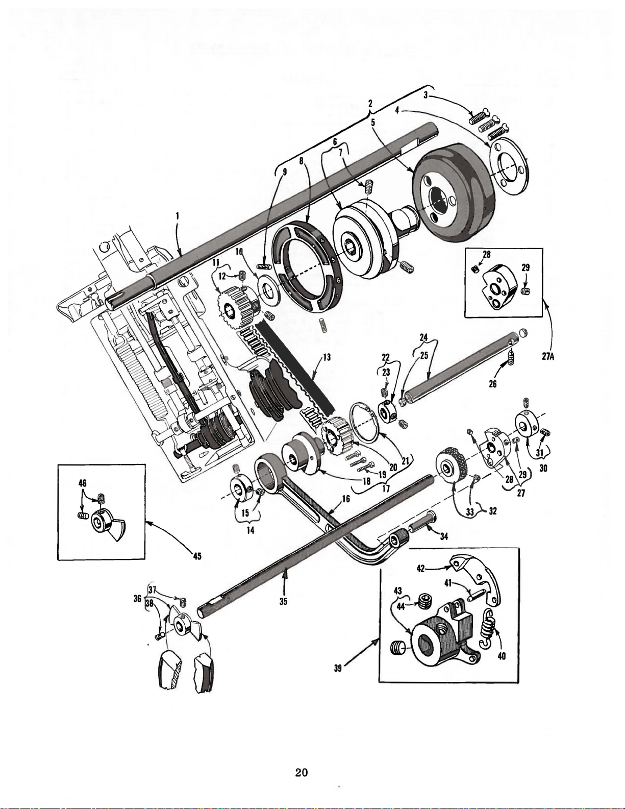
Page 20
20
Page 21

MAIN
SHAFT, HANDWHEEL, RIDGE FORMERS
RIDGE FORMER
DRIVING
PARTS
AND
Ref.
No.
1
2
3
4
5
6
7
8
9
10
11
12
13
14
15
16
17
18
19
20
21
22
23
24
25
26
27
27A
28
29
30
31
32
33
34
35
36
37
38
39
40
41
42
43
44
45
46
Part
No.
14-515
37521 B
22574
61321 L
63921
37521 c
22894 v
22650 AA-7
22894 AD
22894 c
22653
22894
22894 H
22894 AD
22597 A
22894 T
22651
22894 T
22894
22894 T
22894 T
c
BA
155-21
40-197
161-6
171-11
39-146
47-138
433-163
33-163
L-8
161-5
660-414
39-144
c
14-528
18-800
48-189
48-190
39-145
142-16
AB-4
22-333
14-533
44-326
c
444-327-1
21-442
22-337
44-327
99-357
44-333
Description
Main
Handwheel
ThrustWasher-----------------------------------Ridge
Ridge
Thrust
Ridge
Ridge
Collar,
Ridge
Spot
Ridge
Ridge
Thrust
Ridge
Ridge
Ridge
Ridge
Yielding Ridge
Ridge
Shaft----------------------------------------
Assembly
Screw---------------------------------------Hub
Washer
Handwheel-----------------------------------Pulley---------------------------------------
Set Screw
Stitch Length
Set Screw
Former
Screw----------------------------------------
Former
Collar,
SetScrew------------------------------------
Former
Former
Ridge
Screw----------------------------------------
Sprocket
Retaining
for
SetScrew------------------------------------
Former
Screw----------------------------------------
Screw---------------------------------------
Former
-6
---------------------------------------------
Former
Set Screw
SetScrew------------------------------------
Collar
Set Screw
Former
-5,
-6------------------------------------------ 1
SetScrew------------------------------------
Former
Former
Former,
Set Screw
SetScrew------------------------------------
37500-8
Spring
Pin------------------------------------------
Ridge
Ridge
Set Screw
Former,
SetScrew------------------------------------
-----------------------------------Drive
Drive
for
Connecting
Drive
Former
------------------------------------Ring--------------------------------
ridge
Drive
Drive
Drive
------------------------------------
------------------------------------
-----------------------------------Regulating Knob,
Drive
Shaft
for
-----------------------------------Former
----------------------------------------
---------------------------------------
Forming
Forming
for
------------------------------
----------------------------------
--------------------------------
Indicator-------------------------
Sprocket
Belt
ridge
Eccentric-----------------------
former
Styles
Disc--------------------------Disc
-------------------------------Style 37500-9
former
Eccentric
Shaft--------------------------
Crank,
Crank,
Pin-----------..:---------------
-------------------------------
Assembly,
Holder
----------------------
-------------------------drive
Rod----------------------
Assembly------------
drive
37500-1,
shaft
for
Styles
for
Styles 37500-8,
for
--------------------
-------------------
shaft----------
----------------
37
Styles 37500-1,
-5,
-6-----------
for
Style
500-1,
-5,
-9
---
Amt.
Req.
1
1
3
1
1
1
2
1
2
1
1
2
1
1
2
1
1
1
3
1
1
1
2
1
2
1
1
1
1
1
1
2
1
1
1
1
1
1
1
1
1
1
1
2
1
2
21
Page 22

22
~
29
Page 23

Ref.
No.
Part
No.
CYLINDER
STITCH
DEPTH
ADJUSTING
REGULATING
PARTS
Description
AND
PARTS
Amt
Req.
..
1
2
3
4
5
6
7
8
9
10
11
12
13
14
15
16
17
18
19
20
21
22 88
23
24
25
26
27
28
29
30
31
32
33
34
39-144
22894
14-531
45-483
39-148
22653
41332
18-1104
70-75
22617
43232
110-433
660-219
51241 c
39668
110-431
142-18
660-219
22651
110-434
12865
39-147
22894
41375
71-118
18-1098
12990
18-633
471-C544
21-C54
18-C884
20-C117
22894
c
B-8
J
JA-24
R
H
CB-4
T
G
AD
v
w
B
Collar.
Penetration
Penetration
Collar.
Thrust
Penetration
Stitch
Screw.
Spring
Penetration
Spring
Counter
Penetration
Penetration
Collar.
Collar.
Spring.
Cylinder
Adjusting
Nut.
Screw.
KnuckleAssembly--------------------------------
MainSpring------------------------------------Screw.
Nut.
Set
for
penetration
Set
Screw
for
Screw
Washer
Depth
for
Washer
Roll
Pin
Pin-----------------------------------------
Washer-----------------------------------
Plate
Roll
Pin
Screw---------------------------------------
for
Screw---------------------------------------
for
Set
Screw
for
Push
Screw.
for
adjusting
for
for
for
Screw----------------------------------------
main
-----------------------------------
Adjusting
Adjusting
penetration
--------------------------------------
----------------------------------
Adjusting
Regulator
penetration
----------------------------------
Dial
Mounting
------------------------------------
-----------------------------------
Dial
Knob
------------------------------------
Dial
Plate----------------------------
adjusting
cylinder
-----------------------------------
cylinder
Rod
for
screw--------------------------
knuckle
main
spring---------------------------
spring
adjusting
Lever
Lever
adjusting
Screw
Adjusting
dial
mounting
Plate
----------------------------
sleeve----------------------push
push
-------------------------------
assembly----------------------
rod---------------------rod----------------------
cylinder
screw
-----------------------
shaft--------------
Shaft------------------
---------------------screw-------------
----------------------
Sleeve
-------------------
push
rod-------------
plate----------
------------
2
2
1
1
1
1
2
1
1
5
1
1
3
1
1
1
1
1
1
1
1
2
1
1
1
1
1
1
1
1
1
1
1
1
23
Page 24

25
15
24
Page 25

PRESSER
FEET
AND
ATTACHMENTS
Ref.
No.
1
1A
2
3
4
5
6
6A
7
8
9
10
11
12
13
14
15
16
17
18
19
20
21
22
23
24
25
26
27
28
29
30
31
32
33
34
35
36
37
38
39
40
41
42
43
44
45
46
Part
No.
18-1094
FP342
405-590
405-590-3
5-590
122-47
18-1107
137-154
137-157
21-446
14-532
1351 L
75-255
88
16-399
6-56
18-643
450-306
18-1111
89-64
22743
660-219
50-305
30-93
22652
D-8
40-C213
431-L187-1/4
431-L187-3/8
431-M187-1/4
431-M187-3/8
431-H187-1/4
431-H187-3/8
405-592
18-1107
122-48
5-592
22738 F
6-74
405-590-2
5-590
122-47
18-1107
126-60
1732
L
89-64
22743
21-446
14-532
88
1351 L
75-255
16-399
18-643
6-56
Description
Screw,
I
Screw,
Presser
for
Presser
for
presser
for
presser
Foot
Style
37500-1,
Foot
Presser
Chaining
Screw,
Retainer,
for
No.
Retainer,
foot,
for
all
foot,
Assembly,
-5
Assembly,
Styles
for
Style
1/4
inch
----------------------------------for
Style
except
37500-9-----------------
(6. 35
mm)
37500-6-----------------
Foot---------------------------------------
Finger-------------------------------------
for
chainin
marked'
~
finger----------------------------
C",
5/64
inch
(1.
98
405-590------------------------------------
for
No.
405-590-3--------------------------
37500-9
cloth
mm)
opening,
wide
------
notch,
Spring----------------------------------------------
v
Eccentric
Screw,
Edge
Set
Bushing,
Needle
Screw,
Presser
Adjusting
Nylon
Set
Roll
Folder
Folder
Screw,
Foot
Screw-------------------------------------------
Bracket,
Clamp,
Retainer
for
Guide,
for
edge
for
for
retainer
Shaft
guide,
No.
405-590
bushing
-----------------------------
for
No.
405-590
only---------------------
and
shaft----------------------
shaft---------------------------
Guide----------------------------------------
for
needle
Bracket
guide------------------------------
Assembly,
for
Style
37500-9
Screw-------------------------------------
Plug------------------------------------------
Pin--------------------------------------------
for
Style
37500-9-------------------------
for
Style
37500-9--------------------------
only
-----------
---------
Screw----------------------------------------------
S-3
VVasher---------------------------------------------
Folder,
a
Folder,
a
Folder,
producing a 1/4
Folder,
producing a 3/8
Folder,
ing a 1/4
Folder,
ing a 3/8
Presser
for
1/4
inch
for
3/8
inch
for
for
for
for
Foot
Screw,
Chaining
book
(6.
35
book
(9.
52
book
book
book
inch
(6.
book
inch
(9.
Assembly,
for
chaining
seaming
mm)
seaming
mm)
seaming
inch
seaming
inch
seaming
35
seaming
52
on
light
weight
seam,
seam,
(6. 35
(9. 52
mm)
mm)
on
on
on
on
seam,
on
seam,
for
for
light
for
medium
mm)
seam,
medium
mm)
seam,
heavy
for
heavy
for
Style
Style
weight
Style
weight
weight
37500-9
finger----------------------------
Finger-------------------------------------
material,
37500-9-------------
material,
37500-9-------------
weight
weight
for
for
material,
Style
37500-9
material,
Style
37
material,
Style
37500-9
material,
Style
37500-9
-----------------
producing
producing
500-9
produc-
--------produc-
---------
PresserFoot--------------------------------------Screw,
Needle
Presser
for
needle
guide------------------------------
Guide----------------------------------------
Foot
Assembly,
for
Style
37500-8
-----------------
PresserFoot--------------------------------------Chaining
Screw,
Presser
Finger-------------------------------------
for
chaining
Foot
Adjusting
Nylon
Plug--------------------------------------
Crown---------------------------------
Screw---------------------------------
finger----------------------------
SetScrew---------------------------------------
Spring---------------------------------------------Eccentric
Set
Screw,
Screw,
Edge
Bushing,
Screw,
Needle
Retainer
for
for
edge
Shaft
-----------------------------
bushing
and
shaft
----------------------
guide--------------------------------
Guide-----------------------------------------
for
for
retainer
needle
shaft---------------------------
guide------------------------------
Guide----------------------------------------
---
---
Req.
1
1
1
1
1
1
1
1
1
1
1
1
1
2
1
1
1
1
1
1
1
2
1
1
1
1
1
1
1
1
1
1
1
1
1
1
1
1
1
1
1
1
1
1
1
1
1
1
2
1
1
1
1
1
Amt.
25
Page 26

26
Page 27

KNEE PRESS PARTS
Ref.
No.
1
2
3
4
5
6
7
8
9
10
11
12
13
14
15
16
Part
No.
21-372
18-564
20-34
660-454
71-120
131-29
39-147
22894 T
814 L
71-111
4129-18
22508
660-168
22652
F-32
70-76
70-74
17 22651 CD-4
18
19
20
21
22
45-476
22894 J
1442-28
22651
514
CB-4
Description
Spring,
Screw,
Nut,
Retaining
Cylinder
Cylinder
Collar,
for
for
for
knee
knee
knee
press
press
press
stop
-----------------------
stop
-----------------------
stop--------------------------
Ring-----------------------------------
Pull
Rod--------------------------------
Knee
for
Press
knee
press
Hook
------------------------
shaft-----------------------
Screw--------------------------------------Nut--------------------------------------------Knee
Knee
Press
Press
Rod---------------------------------Pad----------------------------------
Screw-------------------------------------Knee
Screw,
Knee
Knee
Press
for
Press
Press
Cushion------------------------------
knee
Rod
Rod
press
Sleeve,
Sleeve,
rod
sleeve------------------
front
---------------------
rear----------------------
Screw---------------------------------------
Knee
Press
Lever--------------------------------
Screw---------------------------------------
Knee
Knee
Press
Press
Shaft--------------------------------Stop
---------------------------------
Screw---------------------------------------
Amt.
Req.
1
1
1
3
1
1
1
1
1
1
1
1
1
1
1
1
2
1
2
1
1
2
27
Page 28

22
25
28
Page 29

ACCESSORIES.
WORK
SUPPORT
PLATE.
BRACKET
AND
MOUNTING
PARTS
Ref.
No.
1
2
3
4
5
6
7
8
9
10
11
12
13
14
14A
15
16
17
18
19
20
21
22
23
24
*25
26
27
28
29
30
Part
No.
660-415
652-16
40-198
144-33
22640
H-224
144-29
404-145
38-16
4-145
22-330
660-219
21-438
115-165
18-1110
18-1110
22706
A
50-297
22650
22652
AE-6
D-12
21201
21388 u
413
404-148
22650
AE-6
22-338
404-146
18-1108
22652
D-8
50-301
144-28
660-488
WR69
660-458
29480
DP
A
Description
Nut
------------------------------------------
Washer--------------------------------------Isolator
Washer
-------------------------------
Isolator--------------------------------------Cap
Felt
Work
Styles
Screw.
Pad--------------------------------------
Support
Pivot
Work
Position
hexagon
Plate
37500-1.
Post
Support
Pin-------------------------------
Roll
Pin
head-----------------------
•
..:omplet~.
-6
---------------------------
furnished
-------------------------------Plate
------------------------
------------------------------
Spring-----------------------------------Work
Screw
Screw------------------------------------
Pivot
37
500-1.
Screw
Screw.
Screwdriver.
overall 7 11/16
Open
End
Post
for
Plate
Screw
Support
Block-------------------
--------------------------------
-----------------------------------Bracket.
-6.
-9
furnished
with
------------------------------
-----------------------------------No.
50-297.
9/64
Wrench.
inch
inches
3/4
on
Styles
round
blade.
------------------------
inch
opening--------------
37
OilCan--------------------------------------Work
Plate.
Set
furnished
with
Style
Screw---------------------------------
37500-9---------
Pin---------------------------------------
Work
Support
Screw
Screw
------------------------------------
------------------------------------
Mounting
Plate.
complete-------------------
Bracket--------------------------
Isolator-----------------------------------
Rubber
37500-9
"L"
(not
Dust
Thread
plate)
Bumper.
for
No.
404-148.
-------------------------------------
Shaped
shown
Cover
Allen
(not
Stand.
Wrench.
on
picture
shown
complete
9/64
plate)--------------------
on
picture
(not
---------------------------------------
inch
plate)
shown
Styles
500-1.
length
on
Style
hexagon
----------
on
picture
with
-6.
-9-
Amt.
Req.
3
6
6
3
3
1
1
1
1
1
1
1
1
2
2
1
1
2
2
1
1
1
1
2
2
1
4
2
1
1
1
1
1
1
*
Available
as
extra
send
and
charge
item.
29
Page 30

NUMERICAL
INDEX
OFPARTS
Part
No.
3-103
W03 •...•.......
4-145
5-589
5-590
5-591
5-592
6-56
6-74
8-143
8-144
14-512
14-514
14-515
14-524
14-528
14-531
14-532
14-533
14-534
SB15
16-194
16-375
16-377
16-389
16-392
16-393
16-399
16-403
17-114
17-150
17-177
17-179
18-269
18-307
18-330
18-492
18-564
18-628
18-633
18-634
18-643
18-644
18-732
18-800
•••••••••
•••••••••
•••••••••
•••••••••
•••••••••
••••••••••
••••••••••
•••••••••
•••••••••
•••••••••
•••••••••
•••••••••
•••••••••
•••••••••
•••••••••
•••••••••
•••••••••
•••••••••
•••••••••••••
•••••••••
•••••••••
•••••••••
•••••••••
•••••••••
•••••••••
•••••••••
••
•••••••••
•••••••••
••••••
•••••••••
•••••••••
•••••••••
•••••••••
•••••••••
•••••••••
•••••••••
•••••••••
•••••••••
•••••••••
•••••••••
•••••••••
•••••••••
18-C884
18-908
18-920
•••••••••
•••••••••
18-1094
•.••••.•
0
••••••
•••••••
••••••••
0
.
••
15
19
23
15
17.
17
19
21
23
17
15
17,25
Page
No.
15
15
29
17
17.25
17
25
17.
25
25
15
15
15
27
21
19
21
23
17.
25
21
17
19
15
15
15
15
19
15
17.
25
15
19
19
19
19
17
17
27
17
25
Part
No.
18-1098
18-1099
18-1100
18-1101.
18-1104
18-1107
18-1108
18-1110
18-1111.
20-34
20-C117
20-129
••••••••
•••••••.
••••••••
•••••••
••••••••
••••••.•
••••••••
••••••••
•••••••
••••••••••
•••••••
•••••••••
21-C54 B ••••••
21-75
21-372
21-429
21-438
21-439
21-442
21-446
22-8
22-53
22-256
22-324
22-330
22-333
22-337
22-338
23-340
23-341
23-342
23-343
23-346
24-333
24-334
24-335
26-185
29
29
30-93
32-299
32-307
32-308
33-149
33-163
36-16
38-16
39-144
39-145
••••••••••
•••••••.•
•••••••••
•••••••••
•••••••••
•••••••••
•••••••••
•••••••••••
••••••••••
•••••••••
•••••••••
•••••••••
••••.••••
•••••••••
•••••••••
•••••••••
•••••••••
•••••••.•
•••••••••
•••••••••
•••••••••
•••••••••
•••••••••
•••••••••
BL-090/036
BL-100/040
••••••••••
•••••••••
•••••••••
•••••••••
•••••••••
•••••••••
••••••••••
••••••••••
•••••••••
•••••••••
Page
No.
23
15
19
19
23
17.25
29
29
25
27
23
17
23
17
27
15
29
19
21
17.25
19
19
15
17
29
21
21
29
19
19
19
19
19
17
17
17
15
.19
.19
25
15
15
15
19
21
19
29
21.23
21
Part
No.
39-146
39-147
39-148
40-38
40-197
40-198
40-199
40-C213
42-28
42-30
44-326
44-327
44-333
45-476
45-478
45-483
46-202
47-138
48-186
48-188
48-189
48-190
50-160
50-297
50-300
50-301
50-305
51-197
51-333
63-34
63-38
63-39
63-41
63-43
WR69
70-74
70-75
70-76
71-111
71-118
71-120
75-212
75-255
•••••••••
•••••••••
•••••••••
••••••••••
•••••••••
•••••••••
•••••••••
S-3
••••••••••
••••••••••
•••••••••
•••••••••
•••••••••
•••••••••
•••••••••
•••••••••
•••••••••
•••••••••
•••••••••
•••••••••
•••••••••
•••••••••
••••••.••
•••••••••
•••••••••
•••••••••
•••••••••
Blk
Blk
••••••••••
••••••••••
••••••••••
••••••••••
••••••••••
•••••••••••••
••••••••••
••••••••••
••••••••••
•••••••••
•••••••••
•••••••••
•••••••••
•••••••••
LS7 5 •••••••••••••
79-41
87
88
89-64
99-346
••••••••••
u
...........
•••••••••••••
••••••••••
•••••••••
••••
•••••
......
Page
No.
21
23.27
23
15
21
29
19
15,
25
27
17
21
21
21
27
19
23
19
21
19
19
21
21
17
29
17
29
25
15
15
15
15
19
15
15
29
27
23
27
27
23
27
15
17.25
15
19
19
17.23,25
25
17
30
Page 31

NUMERICAL
INDEX
OF
PARTS
Part
No.
99-357
110-422
110-431
110-433
110-434
115-165
115-166
115-167
118-37
122-47
122-48
126-60
131-29
137-19
137-154
137-155
137-156
137-157
142-15
142-16
142-18
144-28
144-29
144-33
147-20
147-21
149-33
155-21
161-5
161-6
171-11
191-3
FP342
••••••••••••
404-145
404-146
404-148
405-589
405-590
405-590-1
405-590-2
405-590-3
405-591
405-592
413 ............
426-185
431-H187-1/4
431-H187-3/8
431-L187-1/4
431-L187
••••••••
••••••••
••••••••
••••••••
••••••••
••••••••
••••••••
••••••••
•••••••••
•••••••••
•••••••••
•••••••••
•••••••••
•••••••••
••••••••
••••••••
••••••••
••••••••
•••••••••
•••••••••
•••••••••
•••••••••
•••••••••
•••••••••
•••••••••
•••••••••
•••••••••
•••••••••
••••••••••
••••••••••
•••••••••
••••••••••
••••••••
••••••••
••••••••
••••••••
••••••••
••••••
••••••
••••••
••••••••
••••••••
••••••••
-3/8
••
••
••
••
Page
No.
21
15
23
23
23
29
19
15
19
17,25
25
25
27
19
17,25
17
17
25
15
21
23
29
29
29
15
19
19
21
21
21
21
15
15,
17,
29
29
29
17
17,25
17
25
25
17
25
29
15
25
25
25
25
Part
No.
431-M187-1/4.25
431-M187-3/8.25
433-163
439-7
444-327-1
447-140
449-35
450-306
471-C544
652-16
660-168
660-204
660-219 A ••••
660-219
660-219
660-220
660-414
660-415
660-416
660-454
660-458
660-466
660-488
666-170
666-239
666-276
666-277
666-278
666-279
814 L ••••••••
1160 L ••••••••
1170 L ••••••••
25
1351 L ••••••••
17 32 L
4118-36
4124-60
4129-18
12865
12990
21201
21388
22508
22559 D ••••••••
22560 A ••••••••
22574
22597 A ••••••••
22615
22617
22635
••••••
•••••••••
••••••
•••••••
••••••
••••.
•••••••
••••••
••••••
v
w
••••••
••••••
••••••
••••••
••••••
••••••
••••••
••••••
••••••
••••••
••••••
••••••
••••••
••••••
••••••••
•••••••
•••••••
•••••••
••••••••••
••••••••••
••••••••••
u
........
••••••••••
c
.•••....
A-48
JA-24
CA-12
•••••
••••
....
....
••••
••••
Page
No.
21
19
21
19
19
25
23
29
27
19
29
23,25
23
19
21
29
15
27
29
17
29
19
15,
19
15
15
15
15,
19
27
17
19
17,
25
25
19
19
27
23
23
29
29
27
19
17
21
21
15
23
15
Part
No.
22640
22649
22650
22650
22650
22651
22651
22651
22651
22652
22652
22652
22652
22652
22652
22653
22653
22656
22706 A •••••••
227 38 F
22743
22847 B •••••••
22894
22894 D •••••••
22894 H •••••••
22894 J •••••••
22894 T •••••••
22894
22894
22894
29480
37 521 B
37521
39592
39668 H •••••••
41332 J •••••••
41375
43232 R •••••••
51241
54492
61256
61321 L
61434
61449
63921
80266
H-224
F-16
••••
AA-7
AE-6
AE-10
AB-3
AB-4
CB-4
CD-4
A-6
•••••
A-8
•••••
A-16
D-8
•••••
D-12
••••
F-32
•••••••••
AD
x
•••••••••
G
G
•••••••••
B-8
•••••
L-8
•••••
D-12
•••••••
c
.......
u
.......
v
.......
•••••
DP
•••••
•••••••
c
.......
.......
G
.......
c
.......
•••••••
•••••••
•••••••
T
.......
BA
•••••
••••
••••
•••
•••
•••
•••
•••
•••
•••
•••
Page
No.
29
15
21
29
••
15
19
21
23,
27
19
17,
19
25,29
29
27
23
21
15
29
25
25
15
19,21,23
19
21
27
21,23,27
19
21
15,
29
21
21
15
23
19,
23
23
23
15
19
21
19
15
21
17
27
19
21,
23
23
31
Page 32

WORLD'S
FINES
T
QU
ALITY
*
INDUSTRIAL
SEWING
MACHINES
UNION
SPECIAL
maintains sales
and
facilities throughout the world. These offices
cid
you
in
the selection of the right sewing
equipment for your particular operation. Union
and
Special representatives
tory trained
promptly
tion, there
serve you.
ATLAtiTA, GA.
BOST()N, MASS.
CHICAGO,
DALLAS,
LOS ANGELES, CAL.
NEW
PHILADELPHIA, PA.
ILL.
TEXAS
YORK, N.
and
and
is
a Union Special Representative to
Check with
Y.
are
efficiently. Whatever your loca-
service men
able
to serve your needs
him
today.
MONTREAL,
TORONTO, CANADA
BRUSSELS,
LEICESTER,
LONDON, ENGLAND
PARIS, FRANCE
STUnGART,
service
will
are
fac-
CANADA
BELGIUM
ENGLAND
GERMANY
Representatives
industrial
UNION SPECIAL
400
N.
FRANKLIN
and
cities
distributors
throughout
CORPORATION
ST.,
In
all
Important
the
world.
CHICAGO,
ILL.
60610
 Loading...