

Union Special 36200AK, 36200PA, 36200PH, 36200PJ, 36200PM User Manual
...
MANUAL
PRT9201
STYLES
NO.
ILLUSTRATED
PARTS
LIST
36200
36200
36200
36200
36200
36200
36200
36200
36200
36200
36200
AK
PA
PH
PJ
~M
PX
TA
TH
TJ
TM
TX
a.
Finest Quality
36200
CLASS
INDUSTRIAL
SEWINGE
QUIP
MENT
Manual
No.
PRT9201
36200
36200
33200
36200
36200
33200
Illustrated
AK
PA
PH
PJ
PM
PX
Union
for
36200
Styles
First
Copyright
Edition
By
Special
Parts
the
Series
Corporation
List
1992
36200
36200
36200
36200
36200
TA
TH
TJ
TM
TX
Rights
Reserved
Printed
March.
In
in
All
U.S.A.
1996
Countries
PREFACE
This
parts
conjunction
It
performance.
your
lasting
This
Changes
of
On
in
Este
Cambios
de
parts
or
is
the
machine
service.
manual
in
configuration
the
following
describing
manual
endiseno
la
configuracion
manual
assemblies
with
desire
Parts
and
has
been
design
the
se
ha
has
on
Union
of
Union
listed
are
and/or
in
illustrations
pages
parts
hecho
y
la
en
been
manufactured
comprised
mejoras
prepared
the
36200
Special
Special
in
this
improvements
will
las
be
used
con
on
la
puede
ilustraciones
to
assist
Series
Adjusting
that
manual
with
on
the
may
or
part
found
the
informacion
illustrations
36200
incorporar
you
machines.
Manual
each
utmost
basis
incorporate
machine
are
designed
of
numbers.
Series
basica
una
o
numero
in
locating
INS9202.
precision
available
a
and
machines.
disponible.
pequena
de
It
can
run
at
specifically
to
slight
terminology
modificacion,
partes.
individual
be
used
its
optimum
assure
information.
modification
long
used
in
for
En
las
siguientes
en
la
descripcion
Dieses
Konstruktionsanderungen
Veranderung
Auf
Beschreibungen
warden.
den
Handbuch
der
folgenden
der
wurde
Abbildungen
paginas
de
partes
und/oder
Seiten
Teile,
encontrara
usadas
auf
finden
die
Basis
oder
in
ilustraciones
en
las
maquinas
vorhandener
Weiterentwicklungen
der
Teilenummern
Sie
die
Abbildungen
den
Maschinen
der
y
treminologia
Serie
Information
konnen
bedingen.
und
Baureihe
eine
die
36200
36200.
erstell
geringfiigige
technischen
verwendet
usada
t.
3
1.
Before
starting
operators.
putting
of
each
the
machines
machine
described
is
only
In this
permitted
SAFETY
manual
after
taking
RULES
into
notice
service,
of
carefully
the
instructions
read
the
instructions. The
and
by
qualified
IMPORTANT! Before
2.
Observe
3.
The
it
has
conformed
Each
described
the
4. All
the
5.
Wear
6. In
case
changes
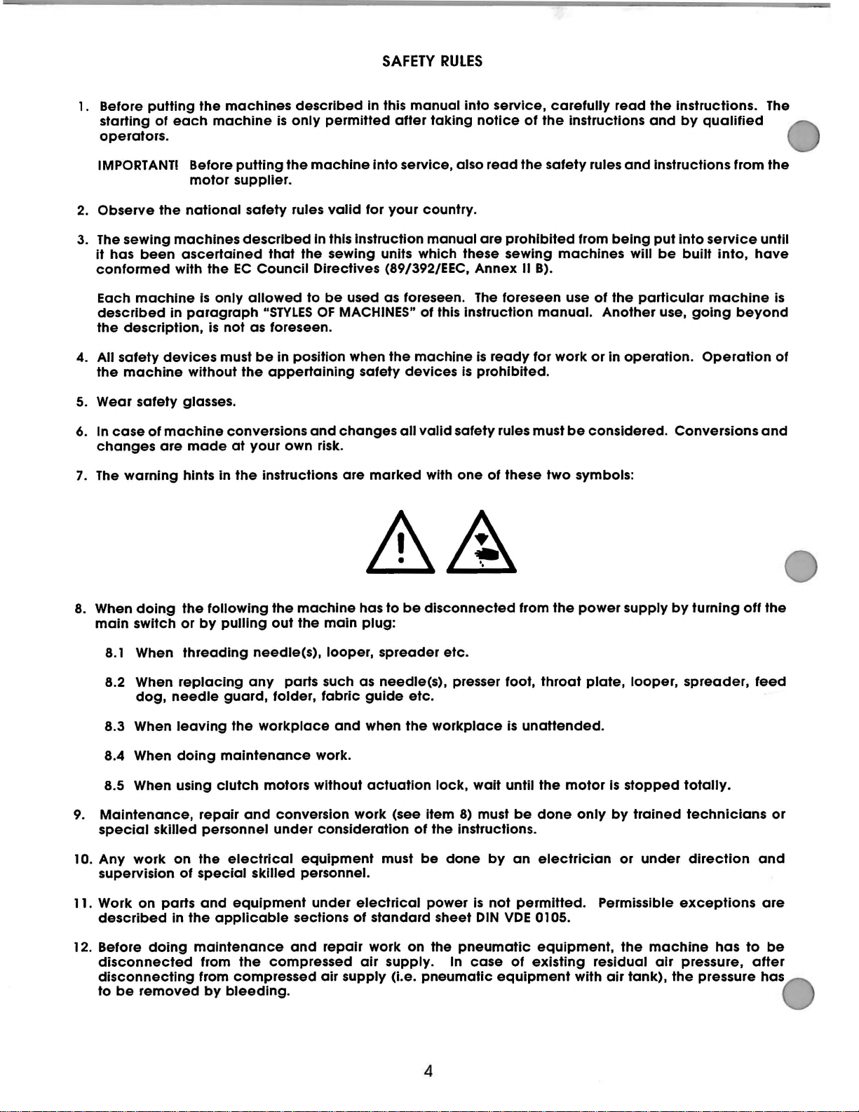
7.
The
the
sewing
description,
safety
machine
warning
machines
been
ascertained
with
machine
in
devices
safety
of
machine
are
putting
motor
national
paragraph
without
glasses.
made
hints
supplier.
the
EC
Is
only
is
not
must
conversions
at
in
the
the
safety
described
allowed
the
rules
that
the
Council
to
"STYLES
as foreseen.
be
in
position
appertaining
your
own
instructions
machine
valid
In this instruction
sewing
Directives (89/392/EEC,
be
OF
and
risk.
Into service, also
for
your
country.
manual
units
which
used as foreseen.
MACHINES"
when
safety
changes
are
marked
the
machine
devices
all
of
this
valid
with
safety
read
are
prohibited
these
is
one
sewing
Annex
The
foreseen
instruction
is
ready
prohibited.
rules
of
these
the
safety
II B).
manual.
for
must
two
rules
from
machines
use
of
Another
work
or
be
considered.
symbols:
and
being
will
the
particular
in
operation.
instructions
put
into
service
be
built
into,
machine
use,
going
Operation
Conversions
from
the
until
have
beyond
and
is
of
8.
When
doing
main
switch
8.1
When
8.2 When
dog,
8.3 When
8.4 When
8.5 When using
9.
Maintenance,
special
0.
Any
1
11. Work
12. Before
work
supervision
on
described
disconnected
disconnecting
to
be
removed
the
following
or
by
pulling
threading
replacing
needle
leaving
doing maintenance
skilled
on
of
parts
in
doing
guard,
the
clutch
repair
personnel
the
electrical
special
and
equipment
the
applicable
maintenance
from
from
compressed
by
bleeding.
the
out
needle(s),
any
parts such as
folder,
workplace
motors
and
conversion
under
skilled
the
compressed
machine
the
main
looper,
fabric
and
work.
without
consideration
equipment
personnel.
under
sections
and
repair
air
supply
has
to
be
plug:
spreader
needle(s),
guide
when
actuation
work
(see
must
electrical
of
standard
work
air
supply.
(i.e.
disconnected
etc.
presser foot,
etc.
the
workplace
lock,
item
8)
of
the
instructions.
be
done
power
sheet
on
the
pneumatic
In
pneumatic
wait
until
must
by
is
not
DIN
VDE
case
equipment
from
the
throat
is
unattended.
the
be
done
an
electrician
permitted.
0105.
equipment,
of
existing
power
plate,
motor
only
Permissible
residual
with
supply
looper,
is
stopped
by
trained
or
the
air
tank),
by
under
exceptions
machine
air
pressure,
the
turning
spreader,
totally.
technicians
direction
pressure has
has
off
to
the
feed
or
and
are
be
after
4
1.
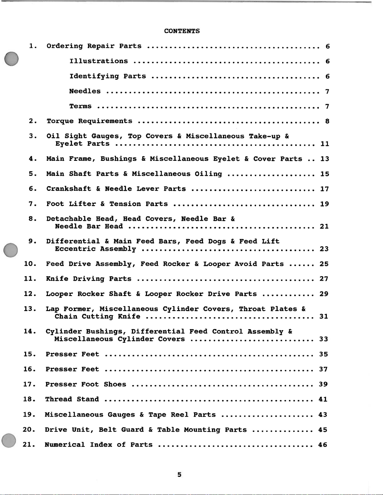
Ordering
Repair
Parts
CONTENTS
. . . . . . . . . . . . . . . . . . . . . . . . . . . . . . . . . . . . . . .
6
2o
3o
4o
Main
5o
Main
6o
Crankshaft
7o
Foot
8o
Detachable
9o
Differential
Torque
Oil
Sight
Eyelet
Needle
Eccentric
Illustrations
Identifying
Needles
Terms
Requirements
Frame,
Shaft
Lifter
. . . . . . . . . . . . . . . . . . . . . . . . . . . . . . . . . . . . . . . . . . . . . . . . . .
Gauges,
Parts
Bushings
Parts
&
Needle
&
Head,
Bar
Head
&
Assembly
. . . . . . . . . . . . . . . . . . . . . . . . . . . . . . . . . . . . . . . . . .
Parts
. . . . . . . . . . . . . . . . . . . . . . . . . . . . . . . . . . . . . .
. . . . . . . . . . . . . . . . . . . . . . . . . . . . . . . . . . . . . . . . . . . . . . . .
. . . . . . . . . . . . . . . . . . . . . . . . . . . . . . . . . . . . . . . . .
Top
Covers
.......................................
&
Miscellaneous
&
Miscellaneous
Lever
Tension
Head
Main
Parts
Covers,
00000000000
Feed
...............................
Parts
Bars,
&
Miscellaneous
Oiling
Needle
Feed
Dogs & Feed
Eyelet
Bar
&
Ta.ke-up
&
Cover
Lift
&
.
Parts
.
6
6
7
7
8
11
13
15
17
19
21
23
10o
11o
12o
13o
14o
15o
16o
17
18o
19o
20o
21o
Feed
Knife
Looper
Lap
Former,
Chain
Cylinder
Miscellaneous
Presser
Presser
0
Presser
Thread
Miscellaneous
Drive
Numerical
Drive
Driving
Rocker
Cutting
Feet
Feet
Foot
Stand
Unit,
Assembly,
Parts
Shaft
Miscellaneous
Knife
Bushings,
Cylinder
Feed
Rocker
&
Looper
Avoid
Parts
. . . . . . . . . . . . . . . . . . . . . . . . . . . . . . . . . . . . . . . .
&
Looper
..................................
Differential
Rocker
Cylinder
Covers
Drive
Covers,
Feed
oooooo•••················
Control
Parts
Throat
Assembly
Plates
. . . . . . . . . . . . . . . . . . . . . . . . . . . . . . . . . . . . . . . . . . . . . . .
. . . . . . . . . . . . . . . . . . . . . . . . . . . . . . . . . . . . . . . . . . . . . . .
Shoes
Gauges
Belt
Index
. . . . . . . . . . . . . . . . . . . . . . . . . . . . . . . . . . . . . . . . .
&
Guard
of
Tape
&
Parts
Reel
Table
Parts
Mounting
Parts
&
.
25
27
29
&
31
33
35
37
39
41
43
45
46
5

ILLUSTRATIONS
ORDERING REPAIR
PARTS
This
views
may
the
manual
of
be
seen
illustration
description
shown.
Numbers
the
position
never
the
be
second
Component
indicated
main
and
20
21
22
23
24
25
26
27
sub-assembly.
the
29478CU
35851L
22729C
269
4761
39145A
22727C
various
in
the
used
parts
by
text
18
has
been
in
their
will
and
the
first
of
the
in
column.
of
indenting
below.
Looper
arranged
sections
actual
be
found a listing
number
column
part
in
of
are
the
ordering
sub-assemblies
their
As
an
Drive
Ball
Nut,
Joint,
Screw
left
Connecting
Nut,
Ball
right
Joint,
Screw
to
simplify
of
the
position
pieces
reference
illustration.
parts.
descriptions
example
Connecting
. . . . . . . . . . . . . . . . . . . . . . . . . . 2
thread
Rod
thread
. . . . . . . . . . . . . . . . . . . . . . . . . . 2
ordering
mechanism
in
the
machine.
of
the
required
numbers
Always
which
use
can
under
refer
to
Rod
upper
•••••••••••••.•.•••
•••••••••••.••••••.•
••.•••••••••••••••••••
•••••••••••••.•••••
lower
•••••••••••••••••••
repair
are
shown
parts
in
with
the
only,
The
reference
the
part
be
furnished
the
the
illustration
Assembly
parts.
so
that
On
the
their
particular
and
merely
number
for
description
••••.
the
page
part
view
number
listed
repairs
on
1
1
1
1
1
1
Exploded
parts
opposite
numbers,
being
indicate
should
in
are
of
the
page
28
It
will
The
so
the
be
ordered.
When a
usage
the
in
the
be
reason
complete
part
will
various
description
noted
is
that
upper
is
common
be
mentioned
machines
illustration.
A
numerical
back.
only
This
a
part
index
will
number
facilitate
IDENTIFYING PARTS
Where
On
an
the
construction
some
of
the
identification
smaller
ones.
PLEASE NOTE:
Part
manual
name
in
the
above
replacement
ball
to
all
in
are
not
and,
of
all
is
if
the
known.
permits,
parts
letter
is
numbers
they
and
Style
example
of
these
joint
and
machines
the
description.
the
same,
necessary,
parts
locating
each
and
on
stamped
represent
appear.
of
that
parts
lower
covered
the
the
shown
the
part
those
in
to
the
On
all
machine
the
individually
ball
However,
specific
difference
in
this
illustration
is
stamped
where
construction
distinguish
same
orders
for
which
ball
joint
in
this
manual
part,
please
studs
is
are
not
sub-assemblies
manual,
when
usage
will
and
with
will
be
is
located
description
its
does
the
part
regardless
include
the
part
not
listed.
reconunended,
should
no
specific
the
parts
be
mentioned
shown
in
at
part
from
was
not
part
number.
permit,
similar
of
which
number,
ordered.
for
the
the
when
6

NEEDLES
Each
kind
number,
blade
and
of
118GAS
118GBS
118GHS
118GJS
118GKS
needle
of
Size
all
has
shank,
stamped
measured
number
needles
DESCRIPTION
Extra
chromium
080/032, 090/036.
Extra
shank,
Same
070/027,
Same
Sizes
Round
groove,
075/029,
both a Type
point,
on
between
represent
packed
short,
short,
chromium
as
as
available
shank,
length,
the
the
and
double
plated.needle.
single
Type
075/029,
Type
spotted,
080/032.
and
Size
groove,
needle
plated
118GBS,
118GHS,
round
shank,
shank
the
sold
065/025, 070/027,
chromium
and
complete
by
groove,
Sizes
groove,
needle.
except
080/032.
except
point,
plated
number.
finish
denotes
the
eye.
symbol
Union
struck
available
struck
with
with
extra
The
and
the
Collectively,
which
Special.
groove,
groove,
Sizes
ball
tapered
075/029.
short,
needle.
Type
other
largest
is
.060"
065/025,
spotted,
available
point.
blade
double
Sizes
number
details.
diameter
the
given
diameter
070/027,
.060"
075/029,
Sizes
and
groove,
available
denotes
The
Type
on
the
075/029,
diameter
080/032.
available
ball
070/027,
the
Size
of
the
number
label
shank,
point.
struck
36211
118GKS
118GKS
When
head
To
sample,
on
Type
TERMS
Prices
are
and
changing
before
have
the
118GKS,
forwarded
insurance.
Retainer
065/025,
75/029
80/032
needles
or
the
label.
are
net
the
the
promptly
Type
A
Size
cash
F.O.B.
needle,
070/027,
needle,
clamp
and
Size
complete
075/029".
and
shipping
no
scarf,
075/029.
APPLICATION
Recommended
36200AK, PA, PH,
Recommended
36200PX,
make
screw
and
number
order
subject
sure
is
tightened.
accurately
should
should
to
change
point.
chromium
for
for
TX
it
filled,
A
Styles
PJ,
Styles
is
fully
be
forwarded.
read
without
charge
plated.
PM,
an
as
is
TA, TH,
inserted
empty
Use
follows:
notice.
made
Sizes
TJ,
in
package,
the
description
"100
All
to
cover
available
TM
the
needle
a
needle
needles,
shipments
postage
7
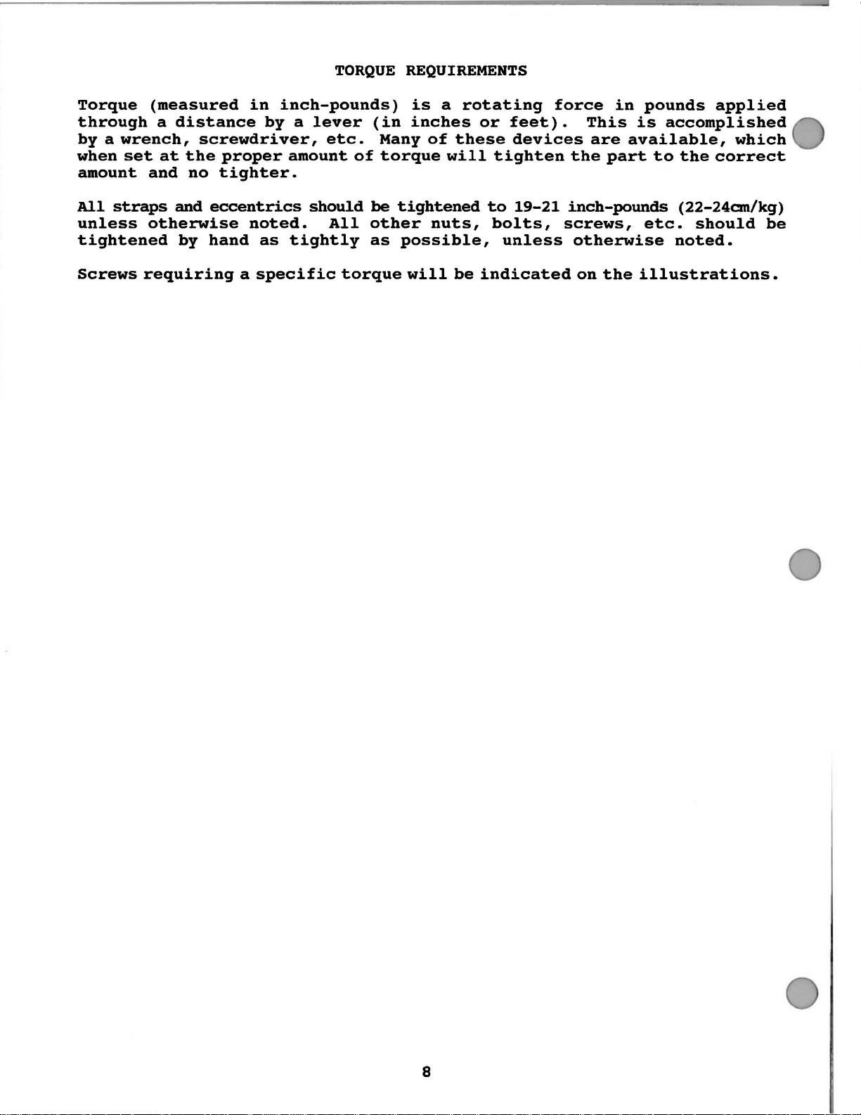
TORQUE
REQUIREMENTS
Torque
through
by a wrench,
when
amount
All
unless
tightened
Screws
set
and
straps
otherwise
requiring
(measured
a
at
distance
screwdriver,
the
proper
no
tighter.
and
eccentrics
by
hand
in
inch-pounds)
by a lever
amount
noted.
as
tightly
a
specific
etc.
should
All
torque
of
(in
Many
torque
be
tightened
other
as
possible,
is
a
inches
of
nuts,
will
rotating
these
will
be
or
feet)
devices
tighten
to
19-21
bolts,
unless
indicated
force
.
the
inch-pounds
screws,
in
This
are
part
otherwise
on
the
pounds
is
accomplished
available,
to
the
(22-24cm/kg)
etc.
illustrations.
should
noted.
applied
which
correct
be
8
EXPLODED
AND
VIEWS
DESCRIPTION
OF
PARTS
9
P023-9
2
10
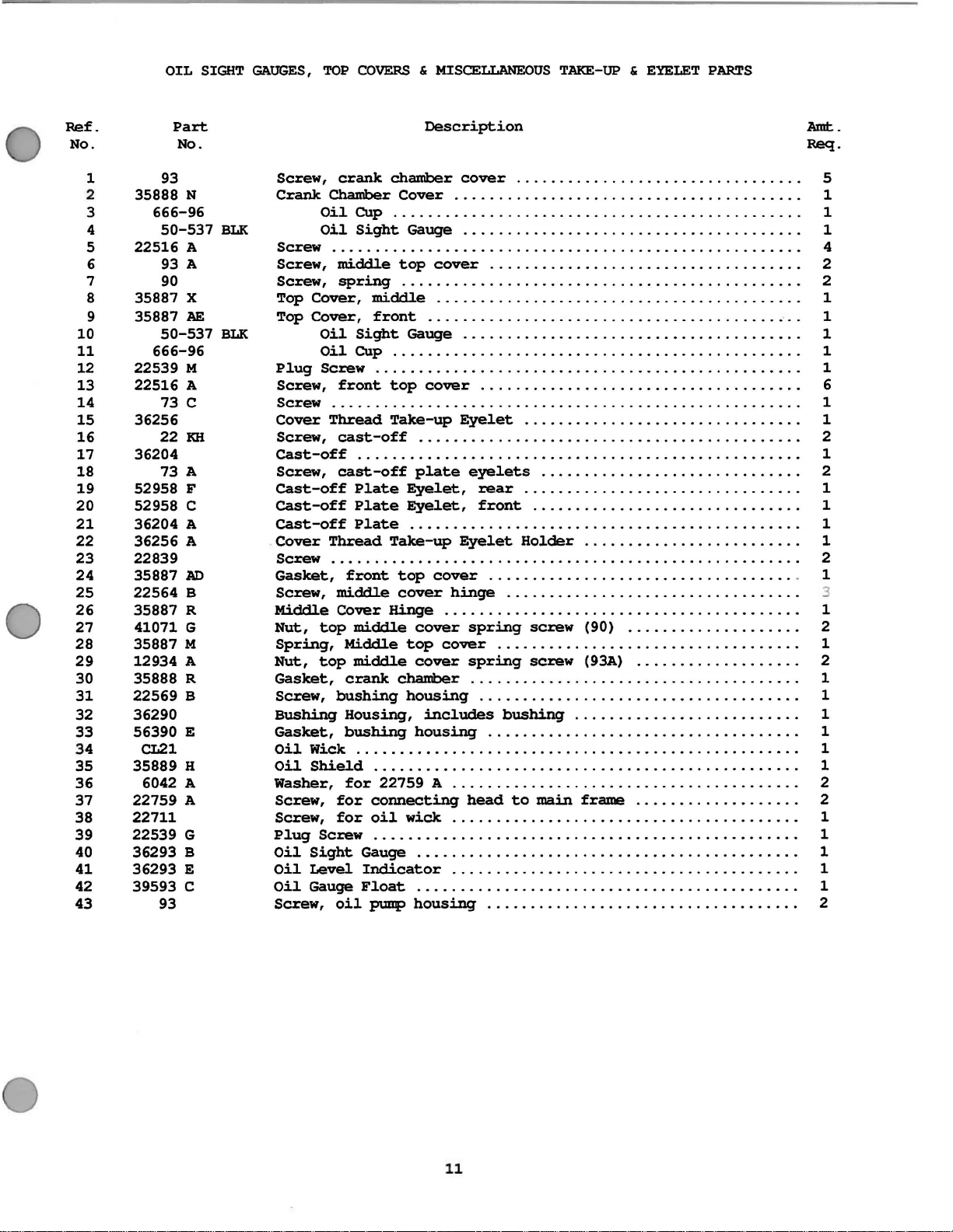
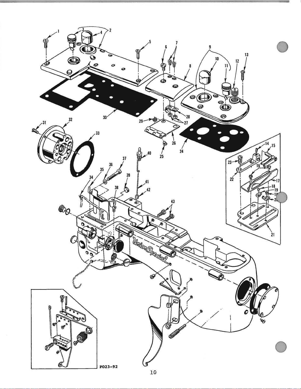
OIL
SIGHT
GAUGES,
TOP
COVERS & MISCELLANEOUS
TAKE-UP & EYELET
PARTS
Ref.
No.
10
11
12
13
14
15
16
17
18
19
20
21
22
23
24
25
26
27
28
29
30
31
32
33
34
35
36
37
38
39
40
41
42
43
1
2
3
4
5
6
7
8
9
Part
No.
93
35888
N
666-96
50-537
22516 A
93 A
90
35887 X
35887 AE
50-537
666-96
22539 M
22516 A
73 c
36256
22
KH
36204
73
A
52958 F
52958 c
36204 A
36256 A
22839
35887
AD
22564 B
35887 R
41071 G
35887 M
12934 A
35888 R
22569 B
36290
56390
E
CL21
35889 H
6042 A
22759 A
22711
22539
G
36293 B
36293 E
39593 c
93
BLK
BLK
Description
Screw,
Crank
Screw
Screw,
Screw,
Top
Top
Plug
Screw,
Screw
Cover
Screw,
cast-off
Screw,
cast-off
cast-off
cast-off
Cover
Screw
Gasket,
Screw,
Middle
Nut,
Spring,
Nut,
Gasket,
Screw,
Bushing
Gasket,
Oil
Oil
Washer,
Screw,
Screw,
Plug
Oil
Oil
Oil
Screw,
crank
Chamber
Oil
Oil
chamber
Cover
cover
.................................
. . . . . . . . . . . . . . . . . . . . . . . . . . . . . . . . . . . . . . . . 1
Cup . . . . . . . . . . . . . . . . . . . . . . . . . . . . . . . . . . . . . . . . . . . . . . . 1
Sight
Gauge . . . . . . . . . . . . . . . . . . . . . . . . . . . . . . . . . . . . . . . 1
. . . . . . . . . . . . . . . . . . . . . . . . . . . . . . . . . . . . . . . . . . . . . . . . . . . . . . 4
middl.e
spring
Cover,
Cover,
Oil
Oil
top
cover
. . . . . . . . . . . . . . . . . . . . . . . . . . . . . . . . . . . . 2
. . . . . . . . . . . . . . . . . . . . . . . . . . . . . . . . . . . . . . . . . . . . . . 2
middl.e . . . . . . . . . . . . . . . . . . . . . . . . . . . . . . . . . . . . . . . . . . 1
front ............
Sight
Gauge . . . . . . . . . . . . . . . . . . . . . . . . . . . . . . . . . . . . . . . 1
..
........
.
..................
Cup . . . . . . . . . . . . . . . . . . . . . . . . . . . . . . . . . . . . . . . . . . . . . . . 1
Screw . . . . . . . . . . . . . . . . . . . . . . . . . . . . . . . . . . . . . . . . . . . . . . . . . 1
front
top
cover
. . . . . . . . . . . . . . . . . . . . . . . . . . . . . . . . . . . . . 6
. . . . . . . . . . . . . . . . . . . . . . . . . . . . . . . . . . . . . . . . . . . . . . . . . . . . . . 1
Thread
cast
Take-up
-off
Eyelet .........
..
...........
. . .
. . . . . . . . . . . . . . . . . . . . . . . . . . . . . . . . . . . . . . . . . . . . 2
......
. . . . . . . . . . . . . . . . . . . . . . . . . . . . . . . . . . . . . . . . . . . . . . . . . . . 1
cast-off
Plate
Plate
Plate
Thread
plate
Eyelet,
Eyelet,
eyelets
.........
.
..........
rear ................................
front
..................
.
.........
.
............
. . . . . . . . . . . . . . . . . . . . . . . . . . . . . . . . . . . . . . . . . . . . . 1
Take-up
Eyelet
Holder
.........................
. . . . . . . . . . . . . . . . . . . . . . . . . . . . . . . . . . . . . . . . . . . . . . . . . . . . . . 2
front
middl.e
Cover
top
Middl.e
top
crank
bushing
Housing,
bushing
top
cover
Hinge
middl.e
middl.e
chamber
cover
top
cover
cover
cover
. . . . . . . . . . . . . . . . . . . . . . . . . . . . . . . . . . . . 1
hinge ...
. . . . . . . . . . . . . . . . . . . . . . . . . . . . . . . . . . . . . . . . . 1
spring
spring
..........
screw
..............
screw
..
...................
(90) . . . . .
..
...................
(93A)
...................
...........
. . . . . . . . . . . . . . . . . . . . . . . . . . . . . . . . . . . . . . 1
housing
includes
housing
. . . . . . . . . . . . . . . . . . . . . . . . . . . . . . . . . . . . . 1
bushing
.......
..............
.
.......
.
..................
.
.......
Wick . . . . . . . . . . . . . . . . . . . . . . . . . . . . . . . . . . . . . . . . . . . . . . . . . . . 1
Shield
. . . . . . . . . . . . . . . . . . . . . . . . . . . . . . . . . . . . . . . . . . . . . . . . . 1
for
22759 A . . . . . . . . . . . . . . . . . . . . . . . . . . . . . . . . . . . . . . . . 2
for
connecting
for
oil
wick
head
to
main
frame
.......
. . .
.........
. . . . . . . . . . . . . . . . . . . . . . . . . . . . . . . . . . . . . . . . 1
Screw . . . . . . . . . . . . . . . . . . . . . . . . . . . . . . . . . . . . . . . . . . . . . . . . . 1
Sight
Level
Gauge
Gauge . . . . . . . . . . . . . . . . . . . . . . . . . . . . . . . . . . . . . . . . . . . . 1
Indicator
Float
oil
punp
. . . . . . . . . . . . . . . . . . . . . . . . . . . . . . . . . . . . . . . . 1
. . . . . . . . . . . . . . . . . . . . . . . . . . . . . . . . . . . . . . . . . . . . 1
housing
. . . . . . . . . . . . . . . . . . . . . . . . . . . . . . . . . . . . 2
·. . 1
...
. .
..
. . 1
Amt.
Req.
5
. 1
2
1
1
1
3
. 2
1
2
1
2
11
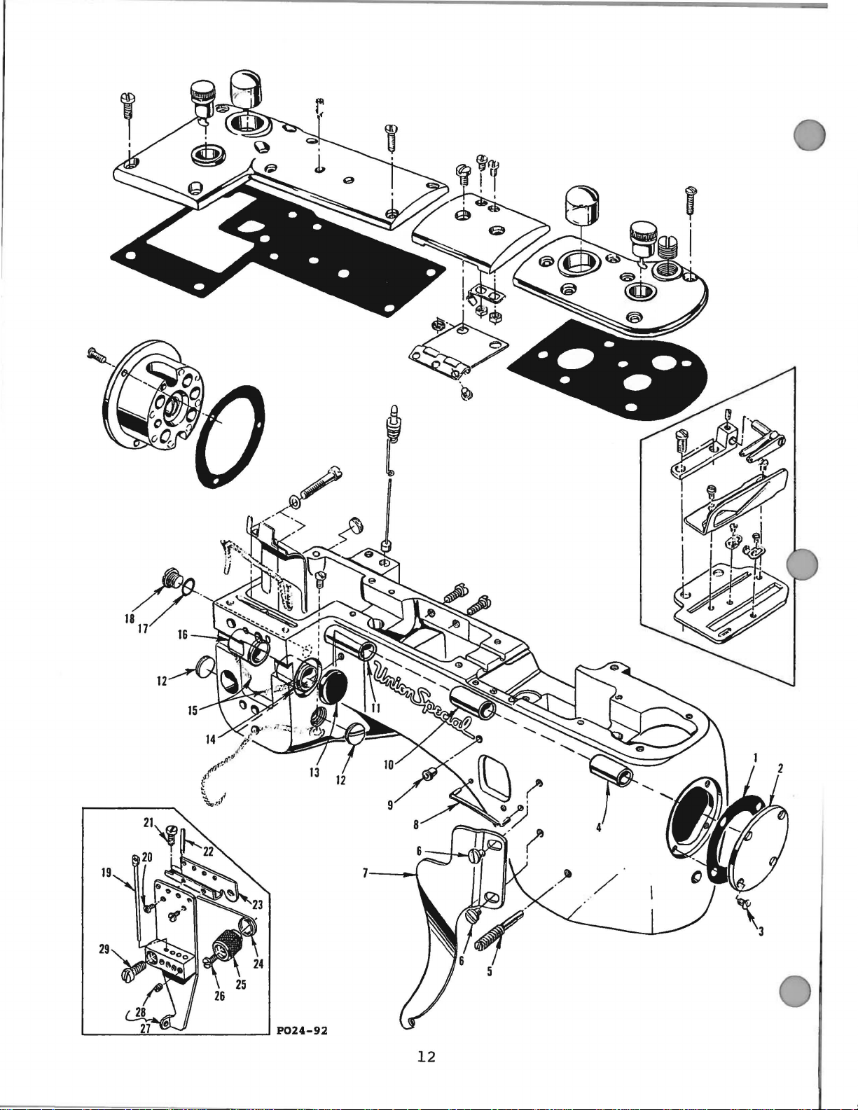
P024-92
12
~N
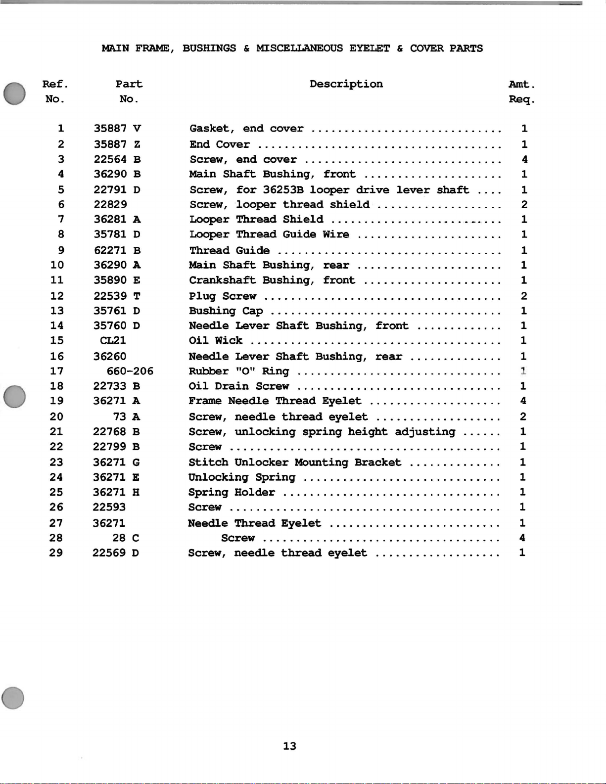
FRAME,
BUSHINGS & MISCELLANEOUS
EYELET & COVER
PARTS
Ref.
No.
1
2
3
4
5
6
7
8
9
10
11
12
13
14
15
16
17
18
19
20
21
22
23
24
25
26
27
28
29
Part
35887
35887
22564
36290
22791
22829
36281
35781
62271
36290
35890
22539
35761
35760
CL21
36260
660-206
22733
36271
73
22768
22799
36271
36271
36271
22593
36271
28
22569
No.
A
A
A
A
B
B
G
E
H
c
D
v
z
B
B
D
D
B
E
T
D
D
B
Gasket,
End
Cover
Screw,
Main
Screw,
Screw,
Looper
Looper
Thread
Main
Crankshaft
Plug
Bushing
Needle
Oil
Needle
Rubber
Oil
Frame
Screw,
Screw,
Screw
Stitch
Unlocking
Spring
Screw
Needle
Screw,
end
Shaft
for
looper
Thread
Thread
Guide
Shaft
Screw
Lever
Wick
Lever
"0"
Drain
Needle
needle
unlocking
. . . . . . . . . . . . . . . . . . . . . . . . . . . . . . . . . . . . . . . . . 1
Unlocker
Bolder
. . . . . . . . . . . . . . . . . . . . . . . . . . . . . . . . . . . . . . . . . 1
Thread
Screw
needle
Description
end
cover
. . . . . . . . . . . . . . . . . . . . . . . . . . . . . . . . . . . . . 1
cover
Bushing,
36253B
. . . . . . . . . . . . . . . . . . . . . . . . . . . . . . . . . . 1
Bushing,
Bushing,
. . . . . . . . . . . . . . . . . . . . . . . . . . . . . . . . . . . . 2
cap
. . . . . . . . . . . . . . . . . . . . . . . . . . . . . . . . . . . 1
Shaft
. . . . . . . . . . . . . . . . . . . . . . . . . . . . . . . . . . . . . . 1
Shaft
Ring
Screw
Thread
thread
Spring
Eyelet..........................
. . . . . . . . . . . . . . . . . . . . . . . . . . . . . . . . . . . . 4
thread
. . . . . . . . . . . . . . . . . . . . . . . . . . . . . 1
. . . . . . . . . . . . . . . . . . . . . . . . . . . . . . 4
front.......
looper
thread
Shield
Guide
. . . . . . . . . . . . . . . . . . . . . . . . . . . . . . . . . 1
Wire..........
rear...........
front.....................
Bushing,
Bushing,
. .
............................
. . . . . . . . . . . . . . . . . . . . . . . . . . . . . . . 1
Eyelet....................
spring
MOunting
. . . . . . . . . . . . . . . . . . . . . . . . . . . . . . 1
drive
shield...................
. . . . . . . . . . . . . . . ...
front.............
rear..............
eyelet...................
height
Bracket..
eyelet...................
.
.............
lever
adjusting......
shaft
....
.
...........
.
..........
.
...........
. . . . 1
_ . . . . 1
.
Amt.
Req.
1
2
1
1
1
1
1
4
2
1
1
1
1
13

II
TORQUE
19-21
in.
{22-24
em/kg)
TO
lbs.
21
'
I
P025-92
14
r------------_J
I
27--/
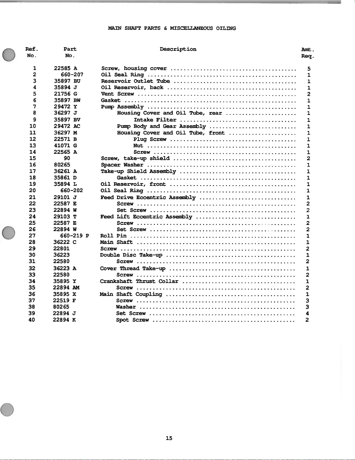
MAlN
SHAFT
PARTS & MISCELLANEOUS
OILING
Ref.
No.
1
2
3
4
5
6
7
8
9
10
11
12
13
14
15
16
17
18
19
20
21
22
23
24
25
26
27
Part
No.
22585
660-207
35897
35894
21756
35897
29472
36297
35897
29472 AC
36297 M
22571 B
41071 G
22565 A
90
80265
36261 A
35861 D
35894 L
660-202
29101 J
22587 E
22894 w
29103 T
22587 E
22894 w
660-219
28 36222 c
29
30
31
32
33
34
35
36
37
38
39
22801
36223
22580
36223 A
22580
35895 y
22894
35895 X
22519 F
80265
22894 J
40 22894 K
A
BU
J
G
BW
y
J
BV
AM
p
Description
ScJ:ew,
Oil
Reservoir
Oil
Vent
Gasket
Pump
housing
Seal
Ring
Reservoir,
Screw
cover
. . . . . . . . . . . . . . . . . . . . . . . . . . . . . . . . . . . . . . . 5
. . . . . . . . . . . . . . . . . . . . . . . . . . . . . . . . . . . . . . . . . . . . . . 1
Outlet
Tube
back
. . . . . . . . . . . . . . . . . . . . . . . . . . . . . . . . . . . . . . 1
. . . . . . . . . . . . . . . . . . . . . . . . . . . . . . . . . . . . . . . . 1
. . . . . . . . . . . . . . . . . . . . . . . . . . . . . . . . . . . . . . . . . . . . . . . . . 2
. . . . . . . . . . . . . . . . . . . . . . . . . . . . . . . . . . . . . . . . . . . . . . . . . . . . . 1
Assembly
Housing
Pump
Housing
. . . . . . . . . . . . . . . . . . . . . . . . . . . . . . . . . . . . . . . . . . . . . . 1
Cover
Intake
Body
Cover
Plug
Nut
and
Oil
Tube,
Filter
and
Gear
and
Screw
. . . . . . . . . . . . . . . . . . . . . . . . . . . . . . . . . . . . . . . . . . . .
. . . . . . . . . . . . . . . . . . . . . . . . . . . . . . . . . . . . 1
Assembly...................
Oil
Tube,
. . . . . . . . . . . . . . . . . . . . . . . . . . . . . . . . . . . . . . . 1
rear......................
front
.....................
.
ScJ:ew . . . . . . . . . . . . . . . . . . . . . . . . . . . . . . . . . . . . . . . . . . . . 1
ScJ:ew,
Spacer
Take-up
Oil
Oil
Feed
take-up
Washer
Shield
Gasket
Reservoir,
Seal
Ring
Drive
Eccentric
shield
. . . . . . . . . . . . . . . . . . . . . . . . . . . . . . . . . . . . . . 2
. . . . . . . . . . . . . . . . . . . . . . . . . . . . . . . . . . . . . . . . . . . . . . 1
Assembly....................................
. . . . . . . . . . . . . . . . . . . . . . . . . . . . . . . . . . . . . . . . . . . . . . . . 1
front
. . . . . . . . . . . . . . . . . . . . . . . . . . . . . . . . . . . . . . . 1
. . . . . . . . . . . . . . . . . . . . . . . . . . . . . . . . . . . . . . . . . . . . . . 1
Assembly..............................
ScJ:ew . . . . . . . . . . . . . . . . . . . . . . . . . . . . . . . . . . . . . . . . . . . . . . . . . 2
Set
Feed
Lift
SCJ:eW
Set
Roll
Pin
Main
Shaft
SCJ:eW
Double
. . . . . . . . . . . . . . . . . . . . . . . . . . . . . . . . . . . . . . . . . . . . . . . . . . . . . . 2
Disc
Screw
Cover
ThJ:ead
Screw
Crankshaft
Screw
Main
Shaft
Screw
Eccentric
Screw
. . . . . . . . . . . . . . . . . . . . . . . . . . . . . . . . . . . . . . . . . . . . . . . . . . . 1
. . . . . . . . . . . . . . . . . . . . . . . . . . . . . . . . . . . . . . . . . . . . . 2
Assembly...............................
. . . . . . . . . . . . . . . . . . . . . . . . . . . . . . . . . . . . . . . . . . . . . . . . . 2
. . . . . . . . . . . . . . . . . . . . . . . . . . . . . . . . . . . . . . . . . . . . . 2
. . . . . . . . . . . . . . . . . . . . . . . . . . . . . . . . . . . . . . . . . . . . . . . . . 1
Take-up
. . . . . . . . . . . . . . . . . . . . . . . . . . . . . . . . . . . . . . . . 1
. . . . . . . . . . . . . . . . . . . . . . . . . . . . . . . . . . . . . . . . . . . . . . . . . 2
Take-up
. . . . . . . . . . . . . . . . . . . . . . . . . . . . . . . . . . . . . . . 1
. . . . . . . . . . . . . . . . . . . . . . . . . . . . . . . . . . . . . . . . . . . . . . . . . 2
Thrust
Collar
. . . . . . . . . . . . . . . . . . . . . . . . . . . . . . . . . . . 1
. . . . . . . . . . . . . . . . . . . . . . . . . . . . . . . . . . . . . . . . . . . . . . . . . 2
Coupling
. . . . . . . . . . . . . . . . . . . . . . . . . . . . . . . . . . . . . . . . 1
ScJ:ew . . . . . . . . . . . . . . . . . . . . . . . . . . . . . . . . . . . . . . . . . . . . . . . . . 3
Washer
Set
Spot
. . . . . . . . . . . . . . . . . . . . . . . . . . . . . . . . . . . . . . . . . . . . . . . . 3
Screw
SCJ:eW
. . . . . . . . . . . . . . . . . . . . . . . . . . . . . . . . . . . . . . . . . . . . . 4
. . . . . . . . . . . . . . . . . . . . . . . . . . . . . . . . . . . . . . . . . . . . 2
.......
..
Amt.
Req.
1
1
1
1
1
1
1
15
r------
--
---
I
I
!
-J
19-21 in.
(22-24
23
22
P026-92
lbs.
cmfkg)
16
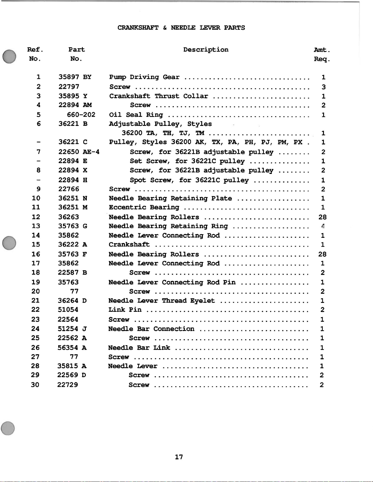
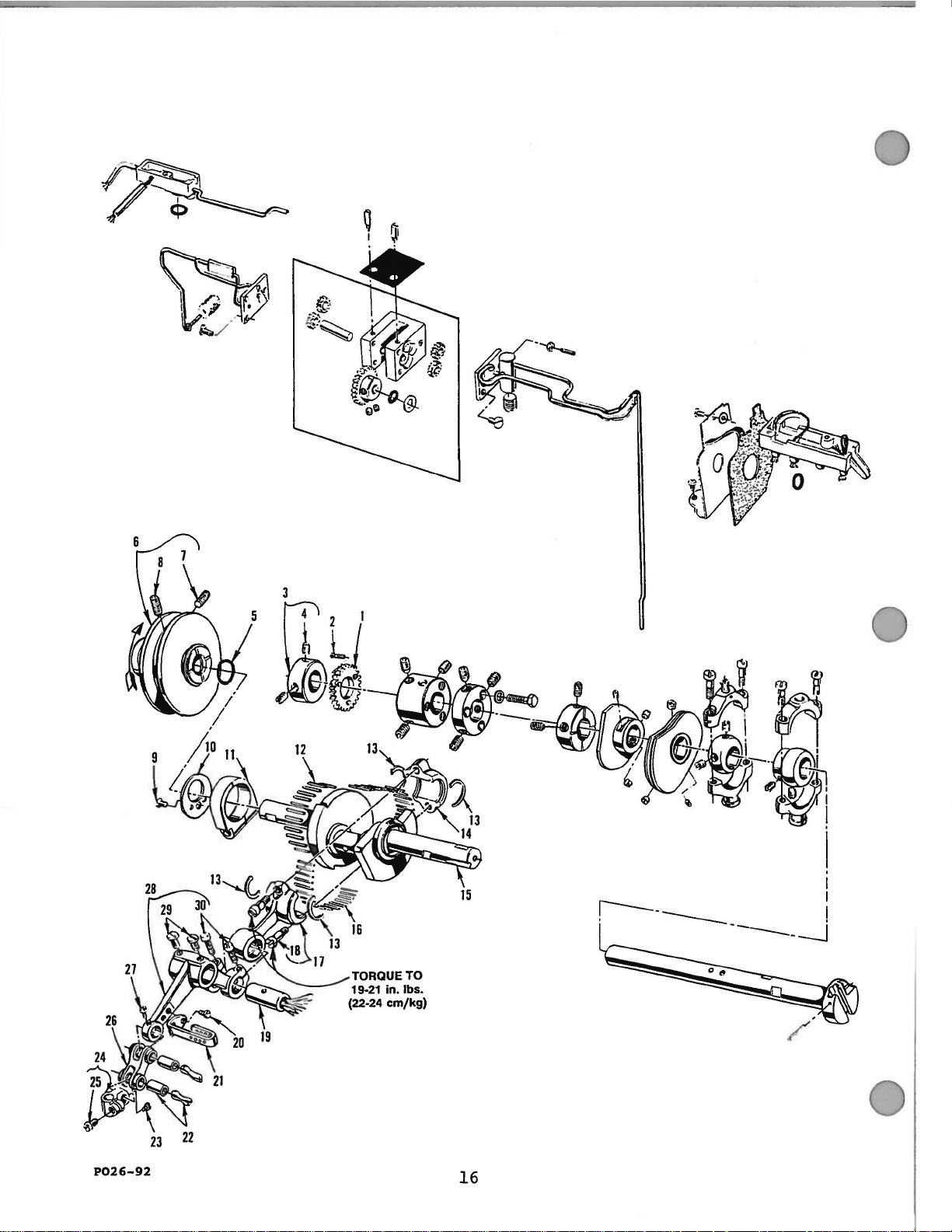
CRANKSHAFT & NEEDLE
LEVER
PARTS
Ref.
No.
1
2
3
4
5
6
7
8
9
10
11
12
13
14
15
16
17
18
19
20
21
22
23
24
25
26
27
28
29
30
Part
No.
35897
22797
35895
22894
660-202
36221
36221
22650
22894
22894
22894
22766
36251
36251
36263
35763
35862
36222
35763
35862
22587
35763
77
36264
51054
22564
51254
22562
56354
77
35815
22569
22729
BY
y
AM
B
c
AE-4
E
X
H
N
M
G
A
F
B
D
J
A
A
A
D
Description
Pump
Driving
Gear
..............................
Screw ..........................................
Crankshaft
Screw
Oil
Seal
Adjustable
36200
Pulley,
Screw,
Set
Screw,
Spot
Screw
..........................................
Needle
Eccentric
Needle
Needle
Needle
Crankshaft
Needle
Needle
Screw
Needle
Screw
Needle
Link
Screw
Pin
..........................................
Needle
Screw
Needle
Screw
..........................................
Needle
Thrust
Collar
.......................
.....................................
Ring
TA,
Styles
Screw,
Bearing
Bearing
Bearing
Bearing
Lever
. . . . . . . . . . . . . . . . . . . . . . . . . . . . . . . . . . .
Pulley,
TH,
for
for
Screw,
Styles
TJ,
TM
36200
AK,
36221B
for
36221C
36221B
for
36221C
Retaining
..........••••.........•.
TX,
adjustable
pulley
adjustable
pulley
Plate
. . . . . . . . . . . . . . . . . . .
Rollers
Retaining
Connecting
.........................
Ring
Rod
. . . . . . . . . . . . . . . . . . . . . . . . . . . . . . . . . . . . . .
Bearing
Lever
Rollers
Connecting
.........................
Rod
....................
.....................................
Lever
Connecting
Rod
Pin
.....................................
Lever
Thread
Eyelet
.....................
.......................................
Bar
Connection
..........................
.....................................
Bar
Link
Lever
. . . . . . . . . . . . . . . . . . . . . . . . . .
. . . . . . . . . . . . . . . . . . . . . . . .
Screw
Screw
.....................................
PA, PH,
PJ,
pulley
..............
pulley
.............
.................
...........
..................
....................
................
...........
PM,
.......
.......
......
PX
.
.
.
.
.
.
.
.
.
.
.
.
.
.
.
.
.
.
.
.
.
.
.
.
.
.
.
.
.
Amt.
Req.
1
3
1
2
1
1
1
2
1
2
1
2
1
1
28
1
1
28
1
2
1
2
1
2
1
1
1
1
1
1
2
2
17
 Loading...