

Page 1

FINEST
STYLES
TYPEN
INDUSTRIAL
SEWING
MACHINES
34700
34700
F
KF
CATALOG NO.
KATALOG NR.
282
CLASS
CYLINDERBED
PARTS & INSTRUCTIONS
Union
Union
Special
Special
Corp.
GmbH
400
North
Schwabstrasee
34700
MACHINE
ZYLINDER-NAHMASCHINE
ERSATZTEILE & ANLEITUNGEN
Franklin Street, Chicago, Illinois, U.S.A., 60610, Telex 254737
33, D-7000 Stuttgart 1, West Germany, Telex 722300
KLASSE
34700
Page 2

SECOND
ZWEITE
EDITION
AUFLAGE
Subject
A.nderungen
DA
2278
to
EG
change
without
vorbehalten
4.
79
1. 5
notice
Printed
in
West
Germany
©
Union
Special
GmbH
May
Mai 1979
1979
1979
Page 3
Al)l
) I I IO N I 0 0 .
•
F::
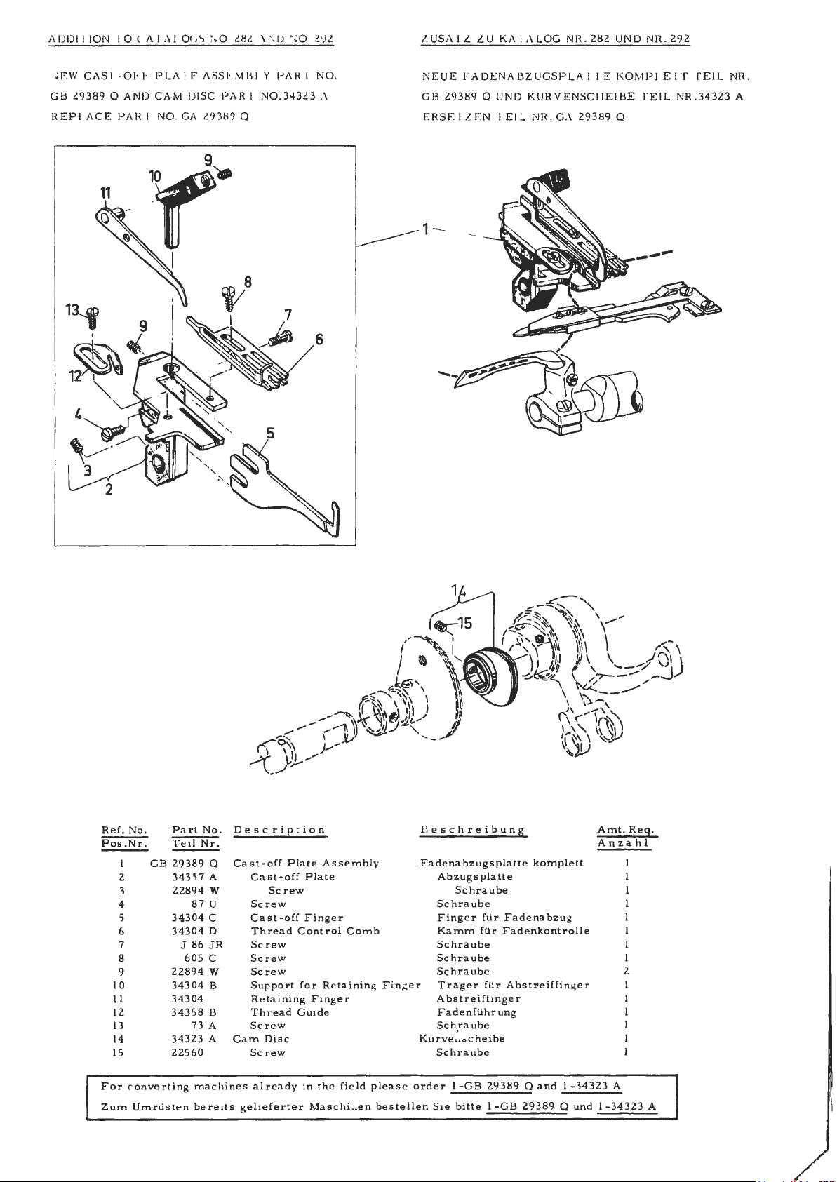
W CAS"I -
GB
29389
REP
L A CE
01
Q A
PAH
~1-·
PlA
ND CAM
I N
O.
11
l8l
I E ASSl::MBI
DISC
PAR
GA l 'J3 8 9 Q
'11/8
I
,\
'D 0 . 29 l
Y l' AH I
I N
O.3·13l3
5
NO.
A
6
Z.USAIZ
NEUE FADENABZUGSPlA
GB
EH
ZU
I\AIAlOG
2931:19
Q UN O K U
SEl'ZEN 1 Ell
NR .
NH.21:12 U
RV
E NSCHE
GA 293
1
'l '
IE
IBE
1:19
NO
NR.292
KOMPLE
TEil
Q
l"f
TEIL
NR.34323
NR.
A
R
ef.
No.
Pos.Nr.
GB
2
3
4
s
6
7 J 86
8
9
10
11
12
13
14
15
on verting machi
F
or
urn
Umr
Z
Part
No.
Teil Nr.
29389
Q
343
57 A
228
94 W
87
U
34304
C
34304
D
JR
60
5 C
22894 W
34304
B
34304
34358 B
73 A
34323 A Ca m
22560
Listen
be r e 1
Description
Cast-off
nes
ts gehef
Plate
Cast-off
Sc
rew
Scr
ew
Cast-off
Thread Control
Screw
Screw
Scr
e w
Support for Retainin
Re ta i
nin
Thread Guide
Scre
Screw
already
g F inger
w
Disc
erter
As se
Plate
Finger
in the fie ld plea s e
Ma sc
mbly
Comb
g
hi..en bes
F ing
B
F a de
er
Kurv
ord
tellen
esc
hreibuns
nab
zug
Abzugsplatte
Sch
Finger fur
K
am
Schraub
Sc
Sc
Tra'.ge
Abstreifh nger
Fa
Sc
chraub
S
er
Sie
splatte
Schraube
raub
e
Fadenabzu
m filr
Fadenkontrolle
e
hraub
e
hraube 2
r filr Abstre iffing e r l
de nfilh rung
h ra
ube
e .. ~cheibe
e
I-GB 2938
bitte
I-GB 29389 Q und 1- 3
komplett
9 Q
and
g
1 -34
Amt.
Anzah
323
A
4323
Re~.
l
A
Page 4
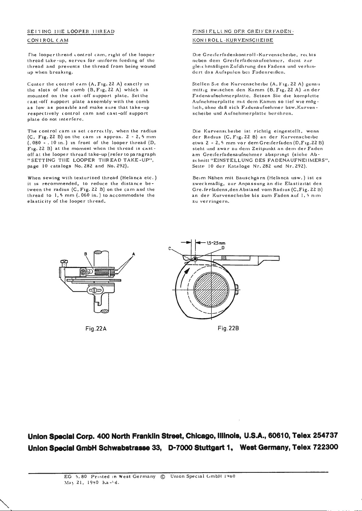
SETTING l'IIE
LOOP
AM
T
he
looper
thread
thread and
up w
enter
the slots
mounted
ast-off
as
low
respectively control
plate
The
(C,
(.
080
F i
g.
off
at
"SETTING
page
When
it
is rec
tween
thread
e
lasticity
thread
t,1kc -
up,
hen
F i g.
22
prevents
breaking
the control c<1m
of
the comb
on the ca
support
as possible a
do not
interf
antral cam
22
B)
10 in.)
B)
at
the
looper
T H E
logs
with
ommended,
radius
I, 5 mm
of
the
on
- .
the
JO c a ta
sewing
the
to
s e
.
1s
the cam
in
moment
thread
(C,
looper
E R T
IIR
antral cam,
rves for unifo
the
thread
(A,
F i
(B,
support
assembly
nd
make
ca m
set corre
front
of
when
take-up (ref
282
to
reduce th
F i
g.
22
060
in.)
thread.
F i
and
1s
THREAD TAKE-UP
a nd
B)
st -off
plate
e r e.
LOOPER
No.
texturized
(.
A D
right
of
rm feed i
from
be i
g.
22
A ) exa c
g.
22
A)
whi
plate.
with
t-off
when the
looper
the
thread
er
292).
e distan
the
the comb
that
2 -
to
cam
ommodate
sure
ca s
tly,
approx.
the
No.
thread (Helan
on
to acc
the
looper
ng
of the
ng wou
tly
in
c h
is
Se t
the
take-up
support
radius
2, 5 mm
thread
is cast
paragraph
ca
etc.)
c e
be-
and
nd
(D,
" ,
t he
the
E I
NSTELL
KONTR
Di e G r
neb
e n dem G reifcrfaclennufnehmer, d1e
g le 1c
hm/i
dc
rt
clas Aufs
Stell
c n Sie d ie
m i tt 1g zw1s c he n de n Kamm
F a de n
Aufnchmcr
lich, ohne
schei
be u
Die
Kurvens hei
der
Ra d i
etw
-
a 2 -
steht und zwar
am Greife
tt
s h ni
Seitc
Be
i m Nii.he n
zweckmaflig,
G r e 1fe rfadens,denAbstand
an
der
zu ver r ingern.
NG
DE R G R E IFER F A
OLL
- K URVENSCHEI BE
eifcrfacle nk
fligen Z u filhrun g d
auf
nchmerplatte.
dal! sic h F a d e na ufnehm e r b
nd
us
2, 5 mm
rfadenaufnehmer
"EJNSTELLUNG DES FADE NA UFNE
10
de r Kata loge Nr.
Kurvenscheibe bis
onl
ro l
l-K
pu lc n bc1 F a dcnre iflc n .
Kurven
platte
m 1t ele m
A u
fnehmcrpl
be
(C,
F ig .
var dem Greif
zu
elem
mil
Bauschga
zur
Anpassung an
es Fadc n s u
schci
Setzen Sic d ie komplctte
Kamm
attc beni
ist
ric
22
B)
an
Zei
tpun
r n (He
u rven
scheibe, rc
bc (
A, Fig.
(B, Fig.
so lie f
htig
eingestellt,
de r
erfaden
kl
an
absprin
282
und Nr. 292).
lan
die
vo m
Radius (C,Fi
zu m
Faden
DE
-
nd
22
22
zw.
h r e
n.
Kurvensche
(D ,F
de m d
gt (s
ca
usw
Elasliz1La
auf
c hl s
nl
zur
verh
1n-
A)
gcnau
A) ,In d
w1e
mclg
Ku rven -
we
1be
ig.22
er Faden
ichc Ab-
IIM
. ) i
sl
l d
g.
22
I, 5 mm
er
-
nn
B)
ERS",
es
es
B)
Fig.22A
C
Fig.228
Union Special Corp.
Union Speclal
EG
'.\1ay
GmbH
5. 8 0 Pnn
21 , 198 0
400
North Franklin Street, Chicago, llllnola, U.S.A., 60610, Telex 254737
Schwabatra-
ted
1n
West Germ
Ka-
hd .
33, D-7000 Stuttgart
an
y ©
Uni
o n
Special GmbH
1,
West Germany, Telex 722300
I
!S
O
Page 5
T
ABLE
N
II
A L T S V E R Z E
OF
CONTEN
T S
C
1-1
N I S
Page
Seit
e
lclenlif1cat1on
13cze i
Lubri alie n
len
O
Threading
Einftideln
Adjusting lns
tellanleilun
E i ns
Hints
for
1-
linweise
Description
Beschreibung
Installing
Montier-
Skipped
Fehlstiche
Exploded
Explosionszeichnungen
hnung
and
und Wa
Adju
fiir
and llints
and
und
Stitches
View
of
M,1
de r Mas hi
Maint
lru
c lions
g · · · · · · · · · · · · · · · · · · · · · · · · • · · · · · · · · · · · · • · · · · · · · · · · • · · • · · · • · · · · · · · · · · · · • · · · 8 ·
stments
Einstellungen,
und
Adjust
Einstellhinwe
· · · · · · · · · · · · · · · · · · · · · · · · · · · · · · · · · · · · · · · · · · · · · · · · · · · · · · · · · · · · · · · · · · · · · · · · · · · · · ·
of
lllne
s ,
Application
ncn,
IIJnwe1se
e na n
rtu
Parts,
ce
ng · · · · · · · · · · · · · · · · · · · · · · · · · · · · · · · · · · · · · · · · · · · · · · · · · · · · · · · · · · · · · · · · · · ·
for
1-Iinwe i
ing Ins
made al
der
die
Machines
se
fu r
tructions
is e
Part
Numbers
Einzelteile,
the
Mas
Hlr
of
Catalog,
fil r d
Fa
tory
im
Werk
gemachl
with
" KL
c hi ne n m il "KL
for "KL
"KLIPPAB
and
Teilenumm
ie
Styles
Benulzung
werden
IPP-I
T"
IPPAB"
IPP-IT",
" ,
Synchronisator
Descriptions
rn
of Mac
hine
de s
K.italogs,
· · · · · · · · · · · · · · · · · · · · · • · · · · · · · · · · · · · · • · ·
.
....
Synchroniz
und Bes
s , Needles
Maschinentypen,
..•.......
rand
und
chreibungen
Wiper
Fadenzieher·
Nadeln'
.................•....
• · · · · · · · · · · · · · · · · ·
· · · · • · · · • · · · · · • · · · · • • · ·
· · · · ·
_
2
3
4 - 7
13
-
_
16
18 _ 23
25
-
3
12
15
17
24
49
Sewing Tables
Nlihtische
Accessories
Zubehor
Thread
Fadenstl!nder
Numerical
Auf
Stand
Index
welcher
· · · · · · · · · · · · · · · · · · • · · · · · • · · · · · · · · · · · · • • · · · · · ··• · · · · · · · · · • · · · · · · · · · · • · · · · • · · · · · ·
· · • • · · · · · · · • · · · • · · · · • • · · · · · · • · · • · · · • · · · · · · · · · · · • · · · · · • · · · · · • · · · • · · • · · · • · · · · • • ·
of
Seite
Parts
finde ich
T e
ile
und ihre
Abbildun
ge n · · · · · · · · · · · · · • · · · ·
·'
· · · • · • · · · · · ' • · · · • • • • ·
50 -
54 -
55
56 -57
58
-
53
60
l
Page 6
IIJl
~N'I
11-'ICA
l'I
ON
O r·· MAC.
E,
,LI, UN I
nu111
.,,.
1H111
onL,oin
S p,
\Vhe
L111ne
1::x;i,nple:
Styles c,f
ON
l,u1·
,,
<.f,1Ksifierl ,,s Ml,
1bt:1· h
·,
i,,I
11 onl
,
S l
un
.i
n,tnic
c1v" one rJr ,norc
the
le tt
St y !,•
n111nber
y
1ninor
""i'
." is
"St
y le 3-17
rno1chine
~E:CIAL
pL,f\•
1ncl
er
"Z".
c
h,ingc!:i
~11ff1,-
00
s s 11nil,1 r
11ncler ., Cl,, s s n11mbc1·
nurnbcJ',
Ex.
in lh.i
,mplc: "Cl.1
t
11 L011l.11!1
ss 3•1
700"
IIINES
1n,1ch1
ne 1H
on
the
.1rcl .,
nd
lc11c r . i,uffi>-.c
Exnmple :
ti L0nt ..
in the le 11,•r
.t
rP
KFZ"
rn
St.,ncl;,rcl
.
in
<.Ollblruc1
,·d 10 t hf'
wh1<.h cliffer b
b
no
l0111•r
.
iden1if1,•d hy
1
n,lt.h1nc.
St } l c nurnbcr
tip, ·c.i.ol. S1.1ncl.1nl
d,
"Styl,•
.. clc
in
but
34700 KF".
"Z"
.
o1
btnncl.i
Sty!,· n11
1on.,
re
from the
s .
Styl
,,
Style
S11•1,
never
rel
n1.t
111b,•r.
gro,q>l'cl
·
•
-
IIEZF:IC.
lede
,
.-
,uf
UN I
tlcm
1 I
NUN
ON SPE
F11·
men
1111mnwrn sind
l'ypc,n-Nu
Je
duch nic
Spe,d,1
\Venn
v
oq~,·non111
n11m1ne r .,
Mnsch1
Kl.os s c
n11mmer
i~
I. Bci
mnw
dPr Buc
1- 1 y pennu
:in ci1wr S1.o
1en
ng,·hlingt.
11c11
t y p
nnurnrn
cl.
,d11rch
s p i
el:
G D
LR
M,\SCII
C IA L fvl,t
s<.
hilcl cle r Mn
i n Sto1nd,1rd
rn
s ine! e i n od e r
hs tn bc " Z " .
inmern cnlh,
ncl.orcl -
w u
rclen, wircl l!in
!:lei s pie I: "Typ
en
glcich.trl
e r z u s
.ommcngef,dll, die
unt
e rsche
"Kla
sse
34700".
IN I::N
bLh
ine
lbl clu r c h
sch
inc, g
und
Spc.d,il
mehrcrc
Bei
,lt
e n
Mo1
s c h
ine nur
11Z11
iger Konstru
idet,
da/J
e111e l'ypenn11111
ckc,
nn1.c 1
c•1ngc!l<•ill. Den S t,
H11
l:
B11
"l'yp
c h s
c hs
l,1bcn
spie
den
geringe
c1n
die Sta ncl.trcl-Typcn
34
700
KFZ
kt i
on
wcrdcn
s ic h vo11
kein
Bu hsl.1be beigef!lg
L1111c1. l')'l>c!n -
111er
1nd,1rd
1,1ben
nngehlln
34 7
00
l<l,.".
"
7..
".
Ver
inderun
".
11ntcr
,•in
de r l'ype11 -
-
gt,
gen
-
er
t
APPLICATION
hi
s c,11.olog ,
T
of mnc
with disc
this
Cl.1s
front,
ti
o n whi
of
hnndwheel
S l'Y
LES
wo
needle, cylinder
r
hine
bnc
le sen
s ., s !isl
retion
s.
Referen
k,
etc
OF
MACIII
1ppli
is
differentinl-(str
Qui
k hange ,
(strel
h-)feed,
to
handle
plished
turn
;'Ill
Re
ar
need
Adjustable
threading.
materinls.
by
i n g
the
be loc ke
needle
to
readjust
Flip-
pressing a push
h;rndwheel. l'humb
d.
gu;i
loop
looper.
Fully
a u
tomatic lubricntion
34700
F,
for
circ11l,1r
made
warp
hemming nec
wear,
a
nd
for
With
for
hems
width.
T
he
capacity
from 2 mm (5/
by
removin
Cylinder
Length
(I
31/32
12
and
01
" C
AT
A ! O G
es sp<•cific.rlly
ed
herein. IL
lu some
.,
ted
clockwi
ce to
.,re
g i
:it the m
Spe i,tl
direction,
ven fro m
,t
se.
NE S
bed cov
e tc h - ) feed.
thumbs rew
for
pucker free
Ensy
stitch
button
rd
driven
it,
when
by sepn
h,inging
e r ,tvo,d e c
up C,'\sl
-off plate
.
hemming
of
light,
and
medium and
ribb
ed knit
k, leg and
underwear,
even
inserting pre-closed
left
and rig
from
ht
8 - 38
of the he
64 inc
g a s
him.
circumference
of
cylinder rig
inch).Standard
16.SPwin
g speed
to
1he S
u,11 ;ils o
Styles of
s
11LI,
lhe ope
hin
e .
Ope
r n
er
senrn n,;'l
,icljustable,
feeding,
length chnnge, acc
nncl
screw ,,ncl
rate ecc
the
entric. E;,sy
for
threading
opernlions
heavy
m,iterials.
"rm
holes
on children's
elastic
hemming g
mm
(5/16-1
mmer
to 4 mm
280
ht
of
can
mm
needle
h)
needle gau
up
to
l.tncl,,rd
be
,1ppl1ed
m,1c h inc~
.ts
right,
r,1tor1s pos i -
ting dire 11011
chines
differenlial
even
on
simultaneously
push
button
ent
ric. No
"t i t h
length.
,ind simpl
the
on
a r
weight
Also
for
on swim-
size
on waists.
uides
arljustable
1/2
inc h)
be
increased
(5/ 3 2 inc
( I l inch
bar
50
ge s 8 ,
6000
st i tc h
SI) les
in
left,
w i
th
-
hard
om-
ticl
eb
flat,
s ,
h)
).
mm
10,
es/mi
IIINWEISE
l)i
cs
St,,nd,,r
fur
ein1ge Spe
wt;rrlen.
11s
w. lwz
Die
.tvlASCJ-IINEN
FUR
DIE
cr
K.11;,log
gi lt bes
d - Maschinentypcn,
zi,d
Die R1chtungsangaben
iehen
Drehri
sich nuf
htung
TYPEN
- M,, s c h 1ne
des
Zweinndel-Zylinder(S1 rec
k-
) r
ra
nsport.
Diff
ere
nt i
verstPllbar,
Pmpfi
D
rilc
llandracles.
r i egelt
Der hin
E x z
St
1 c h
Ei
ns te
Einf/i.delun
sc
hwenkb
al-(Streck-)
dnher
ncllic
her
eines
Ware.
Druckknopfes
R ·
ndelschr
ken
werden.
tere
Nadelanschla
enter angctrieben.
l.
i n
i,:e
n/inde
run
llbnrer
GreiferseitwegexzenlPr.
g .
Abzugsplatte fUr
ar.
VollnutomatischP Schmierung.
3
4700
F,
z um
Rund
sc
hwe
ren
llals-,
Bein-und Arm
nd
Unterwasche, auc h (Ur K indergr
u
s
owie
zum
Mil linkem
fu r Snumb
Der
Stoffrlur
men
rulle
ylinderu
ndnrdnad
l b
e iner Einl
r t
a n g e r e chts
is
6000 Stirhe/min.
n.
ne h
veri;:
Z
Zylinrlerl
St a
zah
BENU
l'ZU
onders ffl
die
Si c ht
11,indrades
Obe
rdecknnhtmaschin
T r
ans
verzugsfreier
Einfache
a11
be
g wi
E b
Pntfallt
g.
s/i
umen
Wi
E inn<l
von leichte
rk-und
hen
md rechte
r e it n
von
c h gn n g
ageplatte von 2 m m a
werd
en.
mfa
ng 28 0 m
e lentfe
rnu
NG
DES
KA
l"A
r d ie dnrin n11fgefnhrte11
Er kann
11nter Umst/ind
ntypen d1eser Kla
wie rec
hts,
vom Pla l z
isl
im Uhr?
links,
dPr Ntiherin
c n
port
dur
c h R /
indelbchraube
Materialtransport
Stichl/ingen/inderung
und gleichzeitiges
11nd
Druckknopf
rd
dur
c h
einf'n bes
GrPif
Strickwa
a u
sschnilt
eines
m S
aumanschlag
8 -
38
im Sii
um e r ka nn d
e in Nac
erfadP
hstellen
E 1
nfache
n na c h o
n,
m i
ttelsrhwer
ren
und
e n a n BadPbekleidun
Gum
m i r in ge s .
m m .
m.
der N;idels t
ng
8,
ang
10,
12 und 16 ga.Stich -
LOG
S
e n
sse
verwend
vorn,
e igersinn.
mil
Differe
au h uc:1
<lur
Drehen
konnen
ver-
onder
be i
und leichte
ben ,111
zum
S/i
umen
ollen geei
, e instellb
urc
h H
uf 4 mm
e 5 0
mm.
n11c
hinl
:111s
nt i.1l -
s,
c h
des
n
-
Pn
11nd
g ne
ar
eraus-
h
e t
en
1,vll
von
t,
.
-
g
34700
KF,
s;ime
th
rend
as 34700
trimmer,
F,
<>xce
pt fitted
,, nrl needle thr
wi th KL IPP-
ead wipe
IT
3
4700
KF,
r.
w1e 34
Un t
erfndenah
fil r N.,dc•
E 1n g
ON SP
Die Typ
Spitz
Einz
elh
l M
Mitt
P z w 1schen
erichtet
illimeter
P r
epared for autom
NEEDL
Ea
n u
p
s
l
mm respec t i
ES
ch
UNION
mber. The t
oint, length
ize
numbf'r, st;,m
arge"
! dia meter
SP E
, g
vel
be t ween s ha nk a
,1t1c
presser foot
CIAL neerl
ype numb
le
hns both
e r
dt>
notes the krnd
roo\'e, finish nnd other
ped
on t
he
sandths
needle
ured
of
o f
y in
blad
thou
e, meas
nd eye .
n ty
detail
sha
in hund
a n i
nch, midway
lifter .
pe and a
o f
sha
s . The
nk ,
deno
r e d s o f a
size
nk ,
tes
NA D
ELN
J
ede
UNI
numm
e r .
be
ns,
der
a
nde
re
g
eprligt, g1bt de n
hundert;,te
i n
der
2
700
F , jPdoc h z u
schneicier
lfaden
.
(ltr automa
ECIAL Nadel hat
ennumrne
e ,
der
eiten.
grollten
r b
Lange, der
Die
Dickennummer,
Durchme
bzw. in
Kolben
slit
KLIPPAB
tisch
eine Typen
ezeic
hnet diP A rt
Rinne,
sser der '
ta u
sendst
und Ohr.
z lic.h
<'
OrLlckerfu
mil Obe
und
und
Fade
e i
des
r-und
/Jlif
ne
'./;,.d,-Jkn
der Oberflad,e und
1m
Nadi>lk
olb
iacielklinge
PI
111
, h
;in,
gemc
n7,
iPher
t ung.
Dirken
Pn <'i
-
l -
n-
ll1
' n
Page 7

NEEDLl~S ( 0111i1111ed)
Cn
ll
.. c1ivc
ple1.,• s
p.1
1..
J'he >1l.111d,1
and
c.,n
lip.
BcJ.,w
om111cnclccl
l'ypf' No.
121
121
To
an
empty
size
label. A co
11
I
Sele
of
thread
dle
Succe
be secu
brand name,
utation
rials and
of
a c
ly , 1yp,•
ymbol,
k,q,:ed
.111d t1ulcl
34
700
he
eq111ppecl
is
the dcs
GUS
GWS
have
needle
packag
number
000
needl
c ti
on
of
used. Thread s hould
eye
in
s s
in
red
for
workmanship
entury,
rel re1..
Kl•'
tll'erllc.
mplete ord
order
the
only
producing
nnd
whit
h i
hy Union Sp<
1)111111enclt•d ,wc
i,
1 '
lype
with
1.rip1io11
DeKLription
Ro11nd
sh.ink, ro1111cl
groove, blitdc inc
SI
ru
I<
Si
Round
groove,
s1r11c
Siz
groove, chromiu111
1.es
70/
sha
blndc
l<
groove,
es
70/027, 80/
ord
e rs
e,
ii
should
es,
proper need
UNION
be forwn rded.
J'ype
to produce"
o p
era
tion
by
use
SPECIAL
~i1.,• 11111nlwr
i; given on
Ill
GUS.On
Ne edle l'yp,•
11ml ,;11.cs ,1v,1il ,
repre
lhe
l.,hel
'<
i.tl Curpor,1l1on.
cllc
for
rf'q11e s 1
Ill
point,
re,1sed,
ba ll
b,tll
027, 80/ 0 2 , 90/ 03
nk,
round
poin1,sh,1rp
in
rc.1se
c hro111111m pl.t1 ccl.
cl, b,
032, 90/
promptly
s,,mple
e r
would re:id:
121
le size i s
of
of needl
highe
for
nnd
needle,
GUS, Size
Union Special mac
st
quality
m o
nc c
or
Use des
80/032
determin
pass freely thro
goo
d s
tit
c h
e s p
ackage
which
is backed
needles
re
than three-qu, rte r s
~<·nl
uf ;,JI
Sty
I l' s •
lhe
G WS w i
1ble
tip, clonbl
"YC
pl.11c,I.
6.
tll
eye,
036.
11rately
the
type
ed
formation.
d under
the< om-
needle
1700
m,1<hinc
lh
,1 s
of
th•
,
!!
potted,
lip,doublc
spotted,
filled,
and
ription
11
•
by siz e
ugh
hin
es
by
a r e
in
m a l e -
h:irp
,.
e
on
nee-
o u r
I'
NADEL
l'ypc11-1111cl Dif'kc11n11m111er Z
~
Na
Spc
Die
,;
3
»cl11nc n
Spil,;1•
• -
N,1chfolg
Dicken
l'ypf'n
12 1 G US
121
Um
s
e
dazu
v
11
Dte Wa
des
Nadelohr gleiten
an
Ein gutes
isl
p-
unserer
Un
Ma te
( l~o
clelb
czci
c i,
e111pfohlene
4700
GW
Nadelbeste
enclen
in,
oder
ollsl/indi
1000
verw
nu r b
io n S p
ri
hn11ng,
11
gep,1ckle11
KF
isl die
.111
, h
,111sgcr1l;,lel
end
clcr e111pfohlcnen
Nr.
S
Sic bitte
geben
die Beschreibung
ge
Na d e
ln, Type
hl
der
e nclet
Er
ei Verwendung
Ma rkenbezeichnung UNION
ecial Na
a l
und
rl
t,t•l 1,11ng)
llb,1111111
die
.111f
11nd
!:>1,111cJ,1rcJn,1clel
J'ype
111
11 cle r N
finclen
Beschreibllng
Runclkolben,
ger,1
cle Rin
ll
ohlkeh
Die
e n
Rundkolben,
Rinne
kehle, gcpr
Dicken
llungen richtig
eine
Sie Typennummer und Dic ke a
Bestellung
richtigen
en
Ntihfadens.
um
ebnis
deln
He r s
lellung
,iede111 E1ike11 von d11rc h U
verk,111ftc11
121 G S . A
,,clel
werclcn.
Sic
die Bes
N.1deln,
Rllndspi tZl! , l
nen,
le,
geprtigt,
70/027, 80/
n , Scha f!
Runcl
lig
t, ver c
70/027, 80/
lee
re Na
auf
dem
wilrde
121
GUS, Dic
Nadeldicke
eine
gute Stic
beim
Betrieb
von
tragen
seit
e n
N,,deln
f1lr
die
11f \V1111sch
l'ypc
Ill
chreib1111g
Sc ha
ft
ver
verchrom
032, 90/036.
spitzc s
verdi
ckt, 6hr verdi
hromt.
032, 90/ 036.
und
prompt
delpackung ode r eine M u
Etikett
z . B .
lauten
ke
richtet sich nac
Der
Faden soil
hbildung
von Union
Nadeln sichergestelll,
de n
SPECIAL
Ruf
hochster Pr/izision
Uber
75 J a
ergcbcn
J\,l,1schinc11 3
GWS 11111 sch,
clic k
charf,
der Nadelpa
80/032
die
,.,chi.
kl:innen die
11ncl
die
<ugclspil~
l, 6hr verdi
t.
zwei gera d e
:i u s
filhren
n.
:
"·
frei durch
zu
gew/ihrleisten.
Speci
gepac
hren.
erh,illli
ckt, Hohl
Benutzen Si
vollsl/
4700
1rfcr
.e
1.wei
cku
h de r
a l M
inrltge
nion
F 11nd
M,1-
c k
l,
zu konn
stern
ng .
Stlirk
das
asc
hin
die
unter
kt sind.
hen
-
Ein
in
a d
e n
el
e
•
e
e n
LUBRICATION
The
oil
pin
to
s
manufactured
Oil
c
Maintain
T
other than keep
sary. While opera
window
o
pu
A
a
has bee n
g, and the r
operate.
ories from Union
is
fill
he
cked
he mac
il
does
mp
1s inoper
daily
nd
011
eservoir mu
Us e
by
ed a t
at the
the oil
hi ne
is automa tically lu
(A,
Fig
. 2 and Fig . 3)
not bubble whe n machine
check before
a d d
ed
if
drained
the
Mobil Oil Company.
the plug screw (A,
right gauge
level
in g
tin
a t iv e .
req
from
st
oil
Specia
the mai n reservoir
g th e
th e m ornrn
ui r e d .
be
which
is
·l. We recommend
a t
betwe
the
e n
the red lines
oil
m u t bub b le
under the
>.
the
machine befo
filled before beg
deliv
ered with the
Pror
Fig.
1),
f r
bricated and
g s
the level
ont
of
filled
mach
is
runmng, the
tart should
the machine
of
in
in e a
Fig.1
re shi
inn
i ng
acce
ex
39
is
the
gau
no
oilin
is nece
the lucite
rm.
oil
be made
s -
A
6LEN
p-
Vor dem
de r
s -
werden, Beniltzen
mitgelieferte
D
.
ge .
g
If
as
stand wird
Ol
De
Schaugla
ges
gefUllt zu
scha
zeigen
irkt die
w
Priifen Sie jeweil s
Ols t
1
Ver
ti.lte r
wi
rd dur
s e s g
ert
as (A,
. W
enn das
Olpumpe
und
ha lten. W
sand wurde
01,
am Olsch
ehalten wer
, e s
Fig
C.1llen Sic, w
Olbeh
01
r O ls p ie ge l m
c h m i
ugl
and
das
01
mull
deshalb
Sie
da;z:u das
Wi r
empfehlen
ch
di e Vers c hraub u
a u gl
ut:l zwischen den beid
ist nichts
lihrend d e s Nli
. 2 u .
Fig
01
be
im Betri
nicht.
var der morg
enn no1wend
a
vor der I
im
Prore
as vor
den.
Die Maschine wird automatisc h
weite
r no twend
. 3) unter
e b der
e ndlic
us der M.1sch
nbetnebn
Zub
ehor
x
ng (A,
ne
a n
en
hen
s m
dem Maschinenarm Bla
Maschine
hen lnbe
1g,
i n e a bg
ahme
von
39
roten Linien
ig
uss
Union Specia
der
Mob
il
Fig
.
1)
der Maschine gepr
01
eingefU
a l s den O
en sich
mcht
t r iebnahme
nach
,
1m
elasse
ge fil
llt
01
AG.
llt,
des
lbeh/ilter
61-
sen
spru
delt
den
n,
l
de r
ilf
t,
,
3
Page 8

t .
'-
C
2
~
0 0
o o
en
-
- 0
I
en
C> ·-
-~ .E
c E
:,
:,
0
(!)
~
lii
-0 -0
C
-0
0 C
~
:,
;;
en
e
·E
a..
E
li;
:,
.0
C>
.0
:=
:,
-
o:::
e
-
a..
o
en
C
QI
.2
-0
:t::
Q)
en
C>
~
_g
Lt)
0,
M
-4
M
m
Lt)
en
N
ln
4
Page 9

-
'VC
-
2•
-
,,
.., o
~ :!:
...
-
-s
,
---f
--
'I z
...
.....
~.1:
"!
-
__j
&..
5
Page 10

Fig.4
Fig.5
Fig.6
THREADING
The mac
Fig. 2 shows
Klipp-it
Fig. 3 shows
is
When
(C,
After
lever
take-up
fully
the
until
threaded.
pressing
Fig.
4)
threading
(D,
and
swung
cloth
the
hines
is
Fig.
plate
plate
are
the
threaded.
the
lever
swings
push
5)
back
cast-off
up
by
and unsc
contacts
threaded accordin
manner
manner
up
pressing
in
which a machine without
in
which a machine
(B, Fig. 4)
for
threading.
looper cast-off
into
its
plate,
position.
the
lever
rewing the
the mac
g lo
the
looper cast-off
plate
For
cast-off
(B,
Fig.
stop
hine
bed.
Fig. 2 and
with
(C,
cleaning
plate
4),
removin
s c
rew
Fig.
can
(A,Fi
Fi
g. 3.
Klipp-it
plate
4)
at
the
be
g
g.
6)
EINFADELN
Die Masc
Fig.
F i
g. 3 zeigt
Dur h Drilcken
aufnehmerplatte
ausgeschwenkl
Na
F i
g.
stellung
nehmers
ausgeschwenkl
drilckt,
(A,
anschlagt.
ch
Fig.
2 ze
dem
4)
a m
die
6)
hinen
igt
Einfadeln
Hebel
zurilckgedrilckt.
kann
Stoffplatte
soweit
werden
das
Einflideln
das
Einftideln einer
des
Hebels
(C,
Fig.
werden.
wird
(D,
Fig.
die
Fadenaufnehmerplatte
werden,
herausdreht
na h
Fig.2
einer
(B,
Fig.
4)
zum
die
Fadenaufnehmerplatte
5)
wieder
Zum
Reinigen
indem
entfernt
man
und
bi s
und
F i
Maschine
Maschine
4)
kann
Einflide
ln nac h
in
ihre
den
die
Anschlagschraub
die
Platte
g3 eing
ohne
mit
die
Ausgangs-
des
Fadenauf-
(C,
Fi
Hebel
am
e f/l
delt.
Klippab.
Klippab.
Faden-
oben
g.
4)
ga
(B,
Fig.
Gehlius e
(C ,
nz
4)
e
Fig
.7
MAINTENANCE
When
the
oil
oil
must
m a gne t
il
machine
chan
ic plug scr e w for
tom cov
change.
first
the
T
he
in
the bot
lat
e m e tallic for
ev
e r y o
ge
be
has
chan
is
oper
to·be
ged eve
er
(A , Fig. 7) .
eign mate
a te d eigh t hou
m a d e a fter si x
ry
si x
month
dra
ini rtg t
It
r ia l s .
is des
It must be
rs daily,
week
s .
he oil
ig ne d
clea
the
s . T
hen
is
loc
a t e d
to accumu-
ned
t
WARTU
Be i e in
St un
z u
wechs
Die magnet
Ol s
die Aufga be m e t a llis c
m u
NG
er t!iglichen
de
n, ist
nehmen
befi
ll
der
. Danach s
elt
werden
i s
che
ndet
s ic h in der B
b i j
edem Olwechsel gere
6
Fig.8
Einsatzdauer der Maschine von
e r
ste
.
Ve r s
Olwechsel
ol!
da s
chlufi
he
F r e m dkorper anzuziehe
01
all
schrau
ode
npl
ini gt werden .
nach sec
e s
a t te
hs Woe hen
echs Mo
be z um Ablass
(A, Fig.
na t e g
7).
Sie
ach
vor-
e-
e n des
ha t
n . Si e
t
Page 11

MAI
N l'
E:NANC
The 111
,1111 oil
have
lo
T
he
main
s
rl'W
mov
•cl
For
lhe
(A,F1g.
From
ave
lo
h
have
to
cle.intng remove
Fig.
I 0).
fill
be
cle,1nccl
oil
filler
(B) ,incl (C
by
turnin
d11ily cle,1
9).
lime
10 l
be le,1necl
be
blown
I~ (Con1111u
e r (
). I he oil filter
g 11 c
ime, 111<·
belt guard
D,
111
(D,
n1ng
and the
0111
ed)
F i
g. 8)o1
pe l
roleum ,11
Fig.
ount
e r
of m,1c
1..ool1ng
w11h
nd l
he
8)
is
,1cc ess1ble
(l-l,l~1g
clockwise
hin
e ,
ribs
fa n bl11cles
comp
r,·~~cd
(A,
F'i1:,
oil
filler
every oil
. '
))
.
remove
of
the
of
lhc
,11
10)
o1ncl
(Ll , l~1g. '
1..hangc.
by
loo
o1n
be re-
lhe
cover
bot I om
handwhecl
r.
Prior
a i r
du
s e
ning
·o e r
l (11,
lo
WARTUNG
))
D,·r
ll,1up1<l
m ,ls
~en
werdcn.
Der
ll,1up1 U
(1-1)
uncl (C )
Drehen
Fdr
den Verschl1113-Slopfen
Von
Zcil
plattc gcreinigl
Presslufl
sc
hutz (A.Fi
cn
lfcrnt wcr
(For1,w1zung)
lfil1er
be,
im Gcgenuhrzeigersinn
d ie
ltlgliche
zu
,1us
(D,F
jedem
<Jlwechsel
lfiller
(0,
zughnglich.
Reinigung
Zeil
mtl
und
gebl,1sen werden.
g. IO)
und das
clcn.
q.;
Fig. 8)
Der
(A,
ssen cl
die
L11flerfl
.8)und
1n
1s1
der
Fig.
1e I<O
Luflleilblech
der
Pelroleum
na
!filler
enlfcrnl.
Maschine
9).
hlrippcn
gel
Dazu
h Lo
(B,
am
mull
!filler
sen
Fig.
(B,Fig.'))
ger<•inigl
cle1· Sc
hrauben
9)
wire!
entfernen Sie
an
dcr
der
(B,Fig
Grund
m il
Riemen
. I
llandrad
O)
dur
-
h
-
, . • 1
e/---
Fig.9
A
B
Fig.10
7
Page 12

ADJUSTING
ALIGNING
I.
Inacrl
ified.
2.
Lo
osen screw
the
needles center
Retight
INSTRUCTION
NEEDLE
:, nl!
e n s c
W e
el
(A,
rew
BAR
of needles
(A,
F i g.
the
Fig.
S
, l y
11) and
needle
11
).
pe
lurn
holes
and
needle
of
s i
ze spe
throat
A
bar
c -
until
plate
.
EINSTELL
AUSRI
C I-ITEN
I.
Setzen
und
Ltisen
2.
Nadelslange
einste
3.
Ziehen
Di
A
LEI
Sie
kc
Sie
c hen.
Sie
T U
NG
DER
NADELSTANGE
e i
nen
neuen
ein
.
die
Schraube
so,
da/J
die
Schraube
Satz Nadeln
(A,
die
Nadeln
(A,
Fig.
F i
entsprechender
11)
und
mittig
g.
11)
wieder an.
drehen
in
die
Type
Sie
die
Stichl5cher
SETTING
When
the
the
right, the
needle
on
8,
IO
on
16
ga.
Loosen
and
move
screw.
Looper
and
looper
used
advantageously
SETTING
The
height
at
its
travel
of
the
left
is
even
(A,
Fig.
or
down
Care
must
needle
THE
looper
to
the
and
machines.
clamp
looper
gauge
HEIGHT
of
needle
with
11)
as
be
bar
while
LOOPER
(Fig.
distan
looper
12 ga.
screw
holder
21225-3/16
gauge
needle
from
the
underside
for
this
required.
taken
making
Fig,11
12)
ce
"A"
point
machines
(B,
Fig.
as
21225-5/32
in
making this
OF
NEEDLE
bar
is
right
to
(Fig.
13)
adjustment
Retighten
not
to
this
is
at its
from center
must
be
and
12)
for
required.
for
8,
10
for
BAR
correct
left
is 1 mm
and
the
of
the
and
screw
disturb
adjustment.
farthest
3/16
5/32 inch =
and
16
adjustment.
when
top
looper.
move nee
the alignement
of
inch=
this
adjustment
Retighten
12
ga.
machines
the
= .
of
the
Loosen
(A).
position
the
ga.
040
right
4, 8 mm
4, 0 mm
clamp
machines
looper
inch
needle
dle
bar
to
can
point
left
eye
screw
up
of the
GREIF
Wenn
mull
Greiferspitze
4, 8 mm
Diese Einstellung
Fig.
Ziehen
Filr
be
und
ga
EINSTELLUNG
Die
spitze
linken
kante
Einstellung die
Nadelstan
Schraube
Beachten
verdreht
ER
EINS
TELL
der
Greifer
der
Abstand
bei
und
bei
16
12)
und
Verschieben
Sie
die
die
12
ga Ma
Maschinen
Nadelstangenhtihe
bei
Nadel
Greif
Pratzschraube
Einstellung
schinen
von
DER
ihrem Weg
steht
er
in
Schraube
ge
nach
(A )
wieder
Sie,
dall
wird.
gleicher
Fig.12
UNG
(Fig.
12)
in
"A"
zwischen
8,
IO
ga .
kann
ist
und
Vorteil
NADELSTANGENHOHE
ist
von
(Fi
g.
Bedar{ nach oben
an.
bei
dieser
seiner
und
Maschinen
nach
die
13)
Mitte
12
ga.
Ltlsen
des
Greiferhalters gemacht
wieder
Greiferlehre
die
Greiferlehre
.
richtig eingestellt,
rechts
nach
und
Oberkante Nad
Htlhe
ste
(A, Fig.
11)
Einstellung die
rechten
rechter Nadel
Maschinen
5/32
inch=
der Pra
an.
21225-3/16
links 1 mm
hen.
Losen
und
sc h i
oder
unt
Endstellung ist,
tzschraube
21225-5/32
Sie
eben
en .
Nadel
und
3/16
inch
4, 0 mm sei
werden.
bei
we
nn
die
links
el5hr
und
fil r
diese
Sie die
Ziehen
s ta n ge nic
=
n.
(B,
8,
bei
16
Greifer-
der
Unter-
Sie
die
10
ht
Right
as
seen
LEFT
of
the
Needle
and
from
the
END
machine
Looper
.
Rechte
von
der
der
Moschine
No
Kein
Nadel
und
LINKEN
Distance
Abstand
Greifer
SEITE
Left Needle
Linke Nadel
Fig.13
Fig.
14
B
..
Fig.15
B
Page 13

SETTING TllE I.OOPF:H
1'0
l'llE
BA K
OF
NEEDLE
SEITLICl!E GREIFEREINS l'ELLUNG
On ith tr.
p;iss
needle (Fig.
This
(B, Fig. 12)
Re ti
gauge selli
dl
e , n nrl ·
looper
ga ug •.
Needle G
Nadelanschlag
,vel
., s clos e ., s pc1t111ible
,1rlJ11stment
ghten
,incl r o
the
ng
onversely,
to
the
uard
14).
Fig.16
SETTING THE
from
right
1..,
111
l,,ting Lhe
l;,
mp
,tft
er setting th
b,1
c l\
of the needl
Rig
ht
Re
chle Nadel
I
•0.02- 0.
REAR
10
to the re,, r o f
be
m ,
1cle by
:,c
re w . A lw ;i y
.dw
., ys chec k
Needle
04
.5 - 1
nrn
pref91'able
vorz119swe1
NEEDLE
le
ft the
loop
e loo
e ,,fter
l
rdl
0.02inch
se
loosen
e r
0.
5mm
GUA
loop
hold
:, che
per
the
R D
e r
the rig
ing
er
c k the
to
b;ic k
s e
tting
setting
point mus t
ht
c l;i
mp
,, s
s c
required.
looper
of
the
of the
the
loop
rew
nee-
e r
Fig.17
Die
G r
hl
Die
Fig.
Ziehen
gestellt
Greifers
eifer
hinter rle r
e Ein.s
tell11ng
12)
Sie die Sc hrn11
st.,
R 19ht Needle
Rechte
d ic
(B,
Greifer,,b
cin
des
eingestellt
EINSTELLUNG
pit
z e
111111:l
re
erhLill
und
e nt s prec he
nd nilchdem
h,,
ben
und
z u r
N;idelrtl kseile,
haben
.
Nadel
DES
bei
hten N;i
ihrem
del
man
ndes Verdrehen
be
wieder ,,n. 0berp
Sie
umgckehrl,
IIINTEREN
den
0020-0
0,5
Weg
c h L tis
Greifer
pr
wenn
.040
mch
mm
van
i e hc n
en
der Pralzs hr,111b •
des Gre
n H
zur Nadel
ilfen
Sie immer die Ste
Sie
Looper
Gre1fer
vorbe
dur
-1
Fig.18
NADELANSCHLAGS
re hls nach
(Fi
g.
14).
iferh.,lt
en
Sie
immer
r ilckseile
den
Greiferabstilncl
Front
Needle Guard
Vorderer
Nadelonschlag
lin
k,;
e r s .
den
llung
The
rear
point,
s id e
in a length
ca I fa
The
crews (A
s
Make
pl
ay
A
readjustment
ry
preferatk 0.040n:h t=~:::=~'r==t=
vorzugsweise
needle
on
Its
of
the
c e
of
rear nee
sure, th;it th
when tig
when
the
o.020-o.04oi
0,5-1,
\OIT'fTI
guil
travel
right nee
of
0,
5 - I
the
needle
dle
gua
and
B,
Fig.
e needle
htening screw
of the re;i r
stit
c h
length
Needl
es
,,
Node n
nch
mm
Front
Vorderer
rd
is
from
dle
, ;,
mm
g ua
rd c;in
15). R e
Needle
Nodelonschlag
set correctly
right
nd
th
= .
02
rd
(Fig.
be
tight
gua
(B,
needle guard
is c
hang
0.004 inch
Guard
Fig. 19
to
left,
needle poin
- .
04 inc h o n the
I 6
"nd
adjusted
e n s c
rd
hold
Fi
.
15).
d.
0,
1
mm
when the l
·re
a c h
es the
t is guid
Fig. I 7).
by loosen
rew
s .
er h;is
is
not
oo
verti
in g
no axial
necessa
pt,
right
ed
end
r
Der
hint
Greiferspitze
rechte
-
no
c h 0 , 5 - I
schla
gs gefilhrt
Der
hintere
und
(A
wie
der
Bea hte n Sie b e
der
Nadelanschlaghalter
-
Eine
Neueinstellung
Stichlangen 'nderung
e re N
ade
l,1nschl
bei
mm
Nadel
der
an
wird
a n s
5)
eingestellt
im Fes
Seite der rec
8, Fig . 1
an.
a g
Bewegung
hten
der
senkrechten
(Fig.
chlag
tziehen
axial
des
hinteren
nicht
ist
richtig
N;idel
16
und Fig.
kann
werden.
der
kein
erforderlich
eingestellt
von rec
erreicht
hts nac h
Fltiche
17).
nach
Ltisen
Ziehen Sie di e Sc
Schraube
Spiel
Nadelanschla
.
hat
und
des
der Schraube
(B, Fig. 15
hat.
links
die
Nadelan-
gs
wenn
Nadel
i s t
die
die
hrauben
),
bei
n
dat:I
Fig .
20
9
•
Fig.21
Page 14

SETTING 1'IIE
The
front
distan
020
distan
Fig.
front
- 0 .
19.
(A
needle
c e
between
of
040 inc
c e
needle
and
looper
Lo
lhc
underside
(0.
T
he
to
The
s
rews
Looper
Greifer
1,2mm
~
,,,,,,
FRONT
guard
the
is
approximately
h) (Fi
the
front
gull
rd can
B,
Fig.
20).
Left Needle
Linke
Fig.22
NEEDLE
is
upp
g.
of
GUARD
set
correctly
e r
edge
18).
the
needles
be adjusted
Retighten screws.
Nadel
~-~~
of
0,
lo
the
5 -
is
by
height,
guard
I,
0
mm
set
a c c
loosening
when
and
ordin
the
g
EI
NST
ELL
Der
vor
wenn
zwischen
Abstand
Der Abs
eingestellt.
Der
vordere
(A
und
wieder
B,
an.
U G
dere
Nadelanschlag
von ca.
tand
zur
Nadelanschlag
Fig.
DES
VORDEHEN
Anschlagoberkanle
0,
5 -
I,
0
mm
Vorderseite
20)
eingeetellt
G H C
NADELANSCl·ILAG
isl
in
der
H6he r
und
ist
(Fig.
der
Nadeln
kann
nach L6s
werden.
Ziehen Sie
ichtig erngeR
Greiferunlerkanle
18).
wird
na c h
en
der Schrauben
die Schr:iuben
S
Fig.
lcllt,
e1n
19
Fig.23
SETTING
Set
i s cast
downward
the
Make
the
By
the
The
"cast-off",
w1
ped
moves
Note,
take-up
SETTING
The
I, 2 mm = 3/64 inch above
highest
This adjus
The feed dogs are
to have
in
the
(B,
s c
rew
feed lo
F i g.
rhe ma
on itudrn
I
rher<Jf
m a
THE
LOOPER THREAD
the
looper
thread
off,
when
the
is
22).
the
thread
looper
prevents
blade
right
finger
FEED
travel
is
made
center
or
g e
t i on
he nut (H ,
as requ
needle
approx.
take-up
(B)
to the r
an
travel
looper
(Fig.
sure, tha t
slot
of
the cast-off support
moving
arrow,
F ig .
in
the
more
finger
(B,Fig,21)
it
under
the
from
the
that
the
d i
scs.
THE
feed
dogs should
point
of
tment
equ
a l
clearance
throat
plate. For
24) and position feed dogs
s .
The different
the
front
24)
a nd r otatin
i n feed dog c
a l direc
or
lo o s e n t
fe Pd do g
take-up,
guides
of
to
DOGS
be
ia l feed d og can be set in -
ccentric
of
i r
tip
2/3
dis
(A,
thread will
controls
the
looper
the
looper,
the
left.
is
exactly
set
to ris e a pp
the
(Fi
g.
23).
with
d a c r os
on all side
this
a d
ear
be s l
ightly c o r
the
th r oa t pla t e f
Fig.
ed.
Re t1ght
TAKE-UP
so
that
the
of
the
left
below
the
c s
are
i n
plate.
Fi
g.
21)
be
drawn
the
looper
thread
when
in
the ente
throat
s c
justme
by
(D).
roxim
plate,
rews (A,
s-the-line-o
s a t t he
nt,
a s
required.Retighten
loo
s e ning sc r e w
Retight
rect
24)
a nd po s1t1on
Pn
nut (H).
looper
needle
upper
the center
in
direction
off.
thread
from
being
the
looper
r o f
a t e
at the
Fi g .
24
f- f e e d
fee
d slots
loo
s e n scr ew s
en
scr
ed
in the
eed
s l
ots.
thread
on
its
edge
of
of
of
a f
ter
the
ly
).
line-of -
(C,
e w
(C).
EINSTELLUNG
Der
Fadenaufnehmer
a
bspringt,
wl!rtsbewegun
(Fig.
22).
Be,;chten
Fadenab
Durch
richtung na
Mit
"Abspringen"
unter die
an rec
v
Beac
uf
A
E
INS
Die Tra
htichst
ra g
Die
D
ie
s o verm1ttelt
ld s t m a n
po r te u
Di ff
24
) u
rli
c kge
Sc
h r a
Der Hauptt
St
ic
(H , F ig .
ach
N
Sie,
z ugsplatte ste
Verschieben
dem
F i ng
Greiferkhn
hts
hten Sie,
nehme
r sche i
T E L L UN G D
nsporte ur e w e r
e n St
en
ere
hpla
ellun
(Fi
g. 23
Einstell
T r a ns
porteu
die Sch r a ub
re
ent
nt ialtransporte u r
nd
dre
he n d
stellt w e rden.
ube
(C ) w i e de r an.
ransporte ur ka
ttenfenste
24)und versch1ebt
der Eins t e
Fig.24
DES FADENAUFNEHM
wird
wenn
die
g c
a. 2/3
da ll
die
ch
vor
ne wird me
er
(B,
kontrolhert,
nach
links bewegt.
dal3 der Finge r (B) gena u m ittig
ben
ER TRA
g e t
).
un g
wird mit de
r e werden seitli
, d a
ll
s ie
s prec hen
es
Exz
r ko rrig1erl
llu
ng, z1ehen
s o einge s l.ellt,
Nadelspit
Aufnehmers
de r FadenfUhrungen
Fi
g.
ge g
ge
wa
en
d.
Z 1ehe n Sie
ze
unterh
en.
21) wir d
ezogen w i r d , wenn si c h d e r Greif
tell
den
I,
2
an alie
(B , F
Z1e he n S1e
kan
e nt
nn gerin
den Haupttr
der link e n N:\dPI b
a lb der Greiferobe r
c he 1ben m1nig
h r Greiferfa
der Greiferfad
er ver
hinder
t w
ird.
NSPORTEU
s o e
mm
n Sc h r a u
n S
ig
n nach L
ers
werd
Sie
RE
ingesl
ell
uber
die Stichplatteno
ben
ch
in
den Stichplatt
tell
en
. 24 )
und
die Schrauben w 1e d
6sen der Sc
(D)
in
Nii
nac
h d ieser Einstellu
gfUg i g
e n. Da
ansporteur dements
d ie Mull.
ERS
d1d l de r
(A , F i g. 2 1)
den
t , d a
t , d a
(A ,
freig!ing
ver
s c hiebt d ie
hrit:htung var -o
in
zu
los
e r (II ) w
Greiferf
l'i
knnte sle
im Schl i
in
a bgezogrn
Pn nac h d
ll der
Greifer
zw1schen
ll sie
in
Fig
. 24) gema,hl.
e n
1g s
rnd. l)
h r a u
Liingsnrhtu
t m a n d
ie
1ede
a de r
ih r
er Ab-
hl
tz
Pfeil
.
em
faden
e r
di r
1
hrer
be
rfl
llc
s~hlitzcn
,, z i
Trn
ns -
er an. O
be
(C ,Fig.
der
z u -
ng
die
ng d ,•r
Mutter
>n •chend
r n .
der
-
he
rr
.
10
Page 15

•
\!J
\
I
A
B
SET
TIN
The
stit
(A,Fig.2
The push
the
handwheel
tating
the
ting
11 counterclockw
ta
Before the
change
Fig.25)
gon socket
lev
arrow,
Aft
c
mecha111sm
and
e r
(E, Fig.
unlocking the
er
setting the clei;i
an
be loc
...
G T
IIE
c h
lengt
)and
button
hand hee
machin<'
loosening
wrench,
ked
-
Fig.
SI
11 Cl!
h I
ll
c
simultan
(A) <'n
and
the stitch len
l clockwi
!Paves the fa
1s loc k,•cl, Wh
which
26)
can
aga111 , i f
25
LENG
hang
ed b y pre
eous
ly
gages within
se
1. e
in
re ases
s c
rcw ( 13,
is d
wun
ch
eccssa
elive
g
le ng
c h l<'n
b s
stit
red stit
-·
-
-
T H
ssing
rota1
in g
hanclwheel
one
gt h c
han
sho
rtens
the
lory
the
e n
removing
ig .
26)
red
in
th
with
the
direction
hange mechanism.
gth,
r y .
the
C
push
button
revolullon
s;:e starts.Ro
the
stitch,ro
stitch.
stitch
cover
with
the hexa
the
machine,
of
mechanism
(C ).
of
length
(B,
the
../
~
E
EINSTELLUNG
Die Stichltinge
(A,
Fig.2
·
eingestellt.
rades
-
gi
d e n
Vor
vcrstellung
-
und lost mit ele m m
clieSchr;iube
richtung
dt>r
Nac
not
5)
rastet
nnt.Drehen
Stich,
d<'m
nach
Stichl/\ngenver
h d Pm E i
we
ndi
g ,
DER
wird
und gleichzeitiges
Nach
splitestens einer Umdrehung
der
Knopf(A)ein
de s Ha
drehen
Versand
blocki
(D,F1g.26)kann
link
nstellen
die Sti
chl
D
Fig.26
STICHLANGE
durch leichtes
ndrades
1m
Gegenuhrzeigersinn
der
crt.
Entfernl
itgeltefertenS
s ge
schwenkt
ste
llung 1st
der
lin g
Drehen
und die
i m
Uhrzeigersinn
Maschine wi
man
de r ll<>lwl
werden
a uf
gewtinschte
cnv,
•r s
tf'llung wi
Dni
c ke n
auf
des
llandrad
vc>rg ri:Hlerl
Stichl
Fii;:.26)
und
di<'
c h
l:i
nge
ed e r
blockie
des
verkleinert
aubendrellf'r
Stichverstellung be
rel d ie
den Dcckel (B,F
cchs
kantschr
(E,
geho
ben.
nSti
de n
Knopf
es
(C)
1-land-
ihn.
a ngen·
ig. 2 )
in Pfeil·
Arret1erun
kann,
wenn
rt
we
·
g
rden.
DIFFERENTIA
The
differential fee d
(A,Fig.
amount
cr<.'ases
NOTE:
DIFFERENTIAL
C H E C K
THE
27).
Turning
of
differential,
the
EVERY CIIANGE
THE CLEARANCE
!-!ROA T
•
L F
ifferenl
FEED RAT
PLATE
•
ED
ratio
is set
the
s c r ew c lo c
turmng it ounterclockwis
ia l feed.
OF STITCH LENG
SLOfS
with reg
kwi
IO
NECESSITATES
OF
T II E FEE D
.
~,· inc
•
ulating sc
rf'ases the
TII
OR
T O
DOGS IN
re w
c d e ·
DIFFERENTIAL
Di,·
Diff
f' rent1
alwir
Fig.
27)
sinn
G egenuhrz
B E
LA
P RU
STICH
e 1ngcstc
vergrollcrt sic h die
e i c r s
ACHTEN SIE:
NGE ODER DER
Fl WERDEN
PLATTENSCHLITZEN
fRANSPORT
k u ng
wird m1t
llt. DrP
inn
NACH
OB
hl
, ve
rklcincrt si,• sich.
DIF
F ERENTIAL
DIE
man die Sch
Diff
e rcn11
J E
DEM VERSTE
TRANS
F R
A
8
der
alwirk
P O
EIG
R,·
g u
lie
raub<'
ung
LLEN
\\
IR
KUNG MUSS
RTE
URE
E H
EN.
ri,chraube (A,
i m
Uhrzeiger-
,dreht
ma n
DE R TIC
GE-
IN
DEN
0 02 inch
0,5 mm
im
I·
ig.28
11
Press
er
Drf Slangen Verb
bar con
n. F · 2 g
dg
. I 9 ·
Page 16
THREAD
The
to
function
1/8
when
If
adjustment.
screw
and
screw.
:i
ny
SETTING
The
if
it
lifter
lower
(C,Fig.11)
bed
and
link
mum
lever
throat
plate.
If
adjustment
direction
Loosen
foot
bar
selling
turning
position
tioned
THREAD
Pull
sion
fabric.
The
sufficient
SETTING
AND
Set
19
(B,
for
take-up
take-up
PRESSER
Regulate
so
foot
is
located
the
should
spring
regulating
counterclockwise
TENSION
lhrend
inch
of
t.he
presser
(A,
Fig.
move
tension
After
point.
HEIGHT
height
is
possible
lever
surf,,ce
should
between
(A,
Fig.29)and
distance
is
released
plate,
until
screw ( D,Fig.11
down
on
connection
and
the
and
in
the
TENSION
the
needle
to
produce
tension
to
THE
TAKE-UP
the
needle
mm=
3/4
Fig.
30).
less
needle
wire
wire
FOOT
the
that
it
exerts
to
feed
directly
machine.
be
slightly
for
the
l:enaion
a11
I.he
of
(B,Fig.28)
and
be
tighten
handwheel
screw
REL ·ASE
rele,111c
I.he
pr<!8ACr
encl
of
i1
11
foot
is
needed,
28),
disc
acljustmcnl.,
the
presser
10
of
the
the
:i
minimum
the
lower
of
0, 5 mm
and
with
the
is
needed,
the
the
throat
and
see
if
previous
threads
uniform
applied
steady
NEEDLE
WIRE
thread
inch
above
Lower
thread
(C,
Fig.
increases
PRESSURE
presser
only
the
work
The
pressure
more than
presser
clockwise
decreases
1.1'.av<'I ,ind
h,, e
loc,,tcd :11.
scpar:,tor
OF
PRESSER
remove
is
fully
presser
bottom
encl
screw
the
feed
turn
needle
).
Then,
plate
guide
with a screwdriver
screw(D,Fig. l !).Check
until
presser
paragraph.
through
stitches
to
the
the
thread.
THREAD
frame
the
it
for
in
the
30)
as
the
spring
enough
uniformly.
behind
foot
i!I
!lei, u1·r c
foot i11
rc:iched i1s
loosen
lhe
.,s
there
BAH
bar(B,Fig.l
the
JHesser
depressed.
bar
of
the
02
the
bar
surface,
the
foot
looper
eyelet
center
more
stitch.Set
low
needle
regulating
pressure
needle
exerted
the
yielding
increases
the
conne
slot
29)
inch,
teeth
handwheel
is
while
needle
can
the
on
thread
needle
as
pressure
pressure.
surface
distance
(B,Fig.
= .
presser
dogs
the
1..1I~, when
r,11s ,•d
to
wilhtn 3 mm
I N
1•11t11
· ..
highest pos it ion.
tension
should
of
of I mm
foot
in
FRAME
possible.
thread
The
by
b:ick
rcqlllrcd.
l)is 11
foot
head
in
should
when
is
below
the
holding
pry
bar
be
removed
eyelets
the
underside
hole
of
mounting
thread,
the
screw
on
regulating
bar
the
section.
the
rcle.,se
of
be
et.
when
Between
lion
opening
the
the
resting
the
in
lowest
up
the
is
and
should
EYELET
(A,
needle
loop.
the
in
the
press
exerted
pressure,
ii
ly
rcl
c:i s c
lever
lhe
m.,
Rclightcn
no
bind
correctly,
the
the
and
guide
in
= .
04
inch,
lifter
lever
be a mini-
foot
lifter
on
throat
operating
position.
the
presser
the
presser
to
obtain
setting
in its
highest
as
set
of
be
just
Fig.
30)
screw
raise
thread
Raising
(D,Fig.30)
presser
screw
head
e r
spring
by
Turning
begin
l11ne
at
foot
the
the
men-
the
the
it
the
of
the
the
by
the
PAOENSPANNUNGS-AUSL0SUNG
s
Die
=
cl
ten-
Faclencnt.spann1111g
1/.l
s c n
bcginn
l:
1,•n
Ende
wcnn
er
Wcnn
cine
(A,F'1g.28)im
s c
hinc
tc
Position.
s
ollte
in keiner
DH
UC
KER
Die
1-lohe
stellt,
dem
der
Zwi
!lc
hen
FUhrung
Gehliuse
S,
hlitzende
(B,
Fig.
DrU kerfufllifterhebel
fuJl a11f
porteure
Wenn
eine
Nahrichtung,
sen
Sie
a11f
die Sti
Schraubendreher
nach
oben,
Schrnube
Nadelstange
Ernslellung,
kann.
FADENSPANNUNGEN
Ziehen
Sie
die
gleichmaflige r Stich0 erzielt
Die
Greiferfadenspannung
der
Fad
EINSTELLUNG
UNO
DES
Stellen
19
mm
ein.
Wird .die
Nadelfaden
Gegenteil.
wie
moglich.
stellt,
wird
DR
UCKERFUSSDR
Stellen
ein,
daJl
gleichmlilliger
schraube ist
a
rm.
Der
et.was
groller
fuJlseitenteil
zeigersinn
zeigersinn
wcnn
seiner
in
und
wenn
(C,
soil
29)
dcr
die
Sie
Spannung
e n
Sie
hoch
Sie
gerade
Bcwcg1111g st.chi. uncl
clcr
hllchst.en
Einst.cllung
Spannungsausltlsehebel
stellen
Bcfest.igen
Position
FUSS-STANGEN-H01
cler DrU
<'
S
mogli
Fufllifter
der
Unlerkant
Fig.
ein
des
ein
Mindestabstand von
Stichpl:itte
uni.er
der
Einstellung
bis
Schraube
chplatte
um
die
(D,
Fig.
den
oberen
ob
der
die
Nadelfaden
ganz
leicht
DER
NADELFADENABZUGSBOGELS
die
Nadelfadenfilhrung
zur
Fadenfilhrung
in
die
Stellen
Wird
die
rechte
die
DrUckerfuJl-Regulierschraube
so
Transport
direkt
Druck
den
sein
erzeugt.
verstlirkt
bewirkt
isl.
richl.ig
d<!r
Drilckerf11fl
Stcllung
notwl'!ndig
den
Spannungsscheibentrenner
Sic
die
Schraube. Nac h
irgend
ein
IENEINSTELLUNG
ckerfuflstange
c h
isl
(B,
Fig.
11)
Lifterhebelgelenks
die
so
Mitte
·e
und
Mindest.;ibsland
die DrU
der
ni
cht
aufliegt. Dabei
Stichplatte
notwendig isl,
Nadelstange
(D,Fig.11),
herunterdrilcken,
Abstande
11)
wieder
Totpunkt
Full,
wie
ein,
gespannt
NADELFADENFUHRUNG
der
Nahl.
Sie
den Nadelfadenabzug
der
Nadelfadenabzugsbilgel
Nadelfadenschlinge
UCK
vie!
Druck
hinter
die
DrlickerfuJlfeder
als
der
Drehen
den
das
Gegenteil.
(B,
den
Dr ckerfufl
28)
vol!
der
DrilckerfuJlverbindung-
unteren
gedrU
sein.
wahrend
ckerfuflstangenverbindung-und
einzustellen.
an.
Drehen
vorher
<lurch
dall
Durch
Druck,
die
auf
wird
.
wird
gerade
ist
Befestigungsschraube
liefer
Hoherstellen
auf
gewlihrleistet
der
Nadelstange
Druck
der
drehen
eingest.ellt,
et.wa 3 mm
m11fl
isl.
isl,
ltlsen
auf
Schwerpunkt
Fig.
niedergedrilckt
Kante
von I mm
(A,
0, 5 mm
kt
wird
drehen
im
unteren
hebeln
erreicht
beschrieben,
Fadenflihrungen und
der
Unterseite
und
am
gestellt
dem
den
die
Regulierschraube
wenn
var
ganz
ausgeltlst
Sie
die
der
Rilckseite
dieser
11)
ist ric
zu
enlfernen,
Armtlffnung
und
Fig.
m il
Sie
so stark eingestelll, dafl
gleichmliflig ablliuft.
Gehause
DrilckerfuJl
wird.
Fed
entgegen
zwischen
29)
sein,
und
der
ssen
Sie
das
Totpunkt
Sie
nun
den
Sie
mit
Danach
das
Hand
hal.
PrUfen
entfernl
des
AM
(A,
bekommen
erreichen
(C,
Fig.
na
groJler.
(D,
Die
auf
dem Masc
erzeugt, sollte
er
£Ur
sie
auszu-
dcm
obers-
h:,ben,
Klemmschraube
der
in
die
gewilnsch-
Einstellung
sein.
htig
einge-
nach-
w u
rde.
und
im
Schraube
wenn
Drilcker-
Trans-
Hand
stehl.
DrilckerfuO
einem
Flihrun
rad bis
Sie
stellen
Steffes
GEHAUSE
Fig.
30)
Fig.
30)
Sie
Sie
30)
so
oben
30)
daJl
Regulier
hinen-
gerade
das
Driicker-
im
Uhr
Uhr-
dem
der
rad
die
werden
mehr
tief
ver-
so
ein
und
die
ziehen Sie d
(B,
ch
Fig.
ist,
dem
Ma-
in
Lo-
g
ie
die
e in
das
-
-
TORQUE
Torque
a
pplied
This
driver
when
torque,
All
2,4
All
by
REQUIREMENTS
(measured
through a distance
is
accomplished
etc.
There
set
correctly,
preventing
straps
and
Nm.
other
nut
as
s ,
tight
hand
in
Nm)is a rotating
are
will
overtightening.
eccentrics
bolts,
screws
as
possible,
by a lever
by a torque
many
of
tighten
should
etc.
unl~ss
these
the
be
force
wrench,
tools
part
tighten
should
otherwise
(in
(in
Newton)
meters).
torque
available,which,
to
be
the
ed
to
tightened
noted.
screw-
required
2,
2 -
ERFORDERLICHE
Drehmoment
m 1 H
ebelarm
Dies
erreicht
Drehmomentschraubendreher
zeuge,
entsprechende
nicht stlirker
Alie Verbindungslager
angezo
Alie and
s o sta r k wie
g
eben
.
(gemesser
(m).
man
die,
wenn
Tei!
,
ge n
werden.
eren Mutt
moglich angezogen
12
DREHMOMENTE
in
mit
einem
das
richtige
auf
das
und
ern,
Bolzen,
Nm)
ist
das
Produkt aus
Drehmoment-Schraubenschliissel,
usw.
Es
gibt
Drehmoment
richtige
Exzent
e r
Schrauben usw. sollen van
werden,
viele. dieser
eingestellt
Drehmoment anziehen
sollen
mit
ca.
wenn
nicht
Kraft
2,
2-2,
anders
ist,
(N)
Werk-
das
4
und
Nm
Hand
ange-
Page 17

8
,
032
1nch , 0,0mm
A
f
HINTS
FOR
ADJUSTMENTS
These
adjustments
crank sha
mechanism
SYNCHRONIZING
CHECKING
I.
2.
3.
4.
5.
6.
The
is
0,
If
not,
I.
2.
3.
ft
Set
looper
Rotate
the
moved
Measure
and
note
Set
the
Rotate
direction
If
direction
looper
left
(Fig.
Measure
machine
8 -
Imm=
the
Remove
Loosen
If
the
sion
"B"
04
inch,
.
the
04
inch,
.
the
has
machine
differen
difference
and
have
THE
IO
dimension
it.
looper
31
dimension "B",
is
bottom
screw (A,
(Fig.
of
Fig.
will
be
components
lo
be
LOOPER
SYNCHRONIZATION
to
its
handwheel
mm
= •
lo
handwheel
moved
B).
synchron
. 03 2 - .
can
c e
31)
lever
of
the
lever
the arrow
ne
of the
disassembled
AND
farthest
clockwise
40
inch
"A",
its
fa
rthesl pos
counterclockwise
10 mm= .
iz
d c
04 inc h
be
syn
cover.
Fig. 32)
between
is
less
(B, Fig.
arrow
is
(B,
32)
to
more tha n
F i
g.
32)
to
30
MADE
essary
position
from
Fig.
40 inc h
Fig. 31.
orre
larger
hronized
.
dimens
than
must
"D".
must
"C".
A
AT
when
needle
or
NEEDLE
to
until
right
31
with a slide
ition
tly
than
io n
0,
8 - I
be
0,
8 - I
be
THE
main
or
replaced
MOTIONS
the
the
lo
left
lo
from
if
dimension
dimension
as
follows:
"A"
mm=.
moved
mm
moved
FACTORY
shaft,
looper
.
right.
looper
(Fig.
rule
the
right.
until
the
right
and
dimen-
032
in
the
= .
032
in
the
drive
has
31 A).
Lo
"B"
"A
-
-
HINWEISE
WERDEN
Diese
Einstellungen
welle
und
oder
ersetzt
SYNCHRONISATION
PRUFEN
I.
Bringen
2.
Drehen
Greifer
3.
Me s
sen
merken
4.
Bringen
5.
Drehen
der
Greifer
(Fig.
6.
Messen
Isl
das
".
Ma
1st
e
I .
2.
3.
Ma ll
schine richtig s
dies nicht
ingestellt
Entfernen
Losen
1st
der
kleiner als
richtung na
Isl
de r Unte r s
(.13,
F i g . 3
FUR
EINSTELLUNGEN
Einzelteile
werden
DER
Sie
Sie
van
Sie
Sie
Sie
Sie
31
B).
Sie
"B"
werden:
Sie
Unterschied
werden
m U
DER
SYNCHRONISATION
den
Greifer
das
Handrad
rechts
mit
einer
es
sich.
den
Greifer
das
Handrad
10
mm
das
Mall
um
0,
ynchronisiert.
der
Fall,
Sie
die
die
Schraube
0,
8 - I
ch "D"
chied
2)
i n
Pfeilrichtun
Fig.31
notwendig,
des
Nadel-oder
ssen.
GREIFER
in
im
nach
links
Schieblehre
in
im
van
rechts
"B", Fig.
8 - I
mm groller als
so
kann
Grundplatte.
(A, Fig.
zwischen
mm
mull der Hebel
verschoben
roll
e r a ls
g n c h " C " vers
DIE
IM
WERK
wenn
Greiferantriebs
UNO
NADELBEWEGUNG
die
rechte
Uhrzeigersinn
10
die
Gegenuhrzeigersinn,
31.
die
Synchronisation
Ma ll
werden.
Endstellung.
mm
bewegt hat.(Fig.31
da s Ma ll
rechte
Endstellung.
nach
links
das
32).
"A"
und
(B ,
0,
8 -
Imm
l
GEMACHT
Hauptwelle,
bis
sich
"A",
Fi
bewe
gt hat.
Mall "A" ,
wie folg
Mall "B"
Fi
g. 3
2)
mull
der
choben w~r
Kurbel-
ausgebaut
der
g. 31
und
bis
sich
ist
t
(Fi
g .
in
P f
eil-
Hebel
den
A).
die
31)
•
Looper
at
,
ts
farthest
position
to
Gre1fers
to
Greife
r g
right
ht
Needles
Nadeln
Rechte Endstellung
~-
Fig.
31
A
at
1t
Looper
Reclite E
ndstetlunades
31
B
F,g.
des
s furthest position
13
Fig.32
Page 18

LOOPlrn AVOI
!'he
loop
colon
·d ma r ks (A
from 70
ta<.l l hc ba ck
approxima
For olh
I.
2. I ooscn screw
3.
/ 0.!.7 10 'J0/ 0 , /,. l'
er
Hcmo
cover.
Io inc
F ig . 33)
e r
ease the motion move
Hd1ghten
er avo
lcly 2/3
n<'ccll
vc
rea
111
D M
id
of lhc
l!
the clolh
s e
lhe
screw.
OTIO
111011
0n
and
I~.
loop,•r,
of
lhc
s iz e s it c
plnlc
(C,
F ig . 3
lhc
looper
d1rect1on
N
,s sci
al
1he
A)
ne,,cllc
the
th·
in
the
fnc101·y
for
the
upper
motion
arrow
dire
needle
bar
blade
as
oil
move
to
lion
descending
follows:
"A",
1-· ,g .
33
lw nef'Cllc points should
with
wny
clown
an
be changed
nncl
3).
a vo id
of
11
lo
the
s i
zes
con
of
the
reservoir
screw
lo de-
to
"B"
-
looper.
(C,
.
Der
Grl!1ferseitenweg
90/036
cingcstcllt.
bcwcgung ca.
Fllr
I.
2.
3.
1m Werk
andere
Nehmcn
ab.
Losen
Vcrsch1eben
(C,Fig.33)
Seilenweg
wieder
a11f
Di e
nclclsp
2/ 3
untcrhalb
Nacleld1ckcn
Sic
die
Sie
die
Schraube
Sie
in
Pfeilrichlung
in
Richtung
an.
wire!
che
farbig•'
it z
cn
kann
Stoffplatte
ftlr
einen
nach
filr
die
/\farkicrungen
sollen
cler Gre
er
wic
und
(C,
Fig.
grti/!eren
nach
''B".
Nadelclickcn
den
Greifer
ifcrkante
folgt
verstellt
den
oberen
33).
Seilenweg
"A"
und
Z i
ehen
von 70/
(A
und
b<'i
ber,lhrcn.
lkammerdc
filr
e i
Sie
die Schraube
B,
d<'r
werdcn:
di e
nen
kleincren
027
bis
Fig.33A)
Abwlirts-
Schraube
kel
TIMING
The
a
After loosemng the eccentr
e
ccenl
and D to
0.
loop
a
nd
The corresponding
Fig.
OF
THE
loop
er avo
set
screw
ric(A,
016 inch) between
t;iking
marked
36.
id
and
can
Fig.
35) c
obtain a distan
ti m e (Fig .
by
colore
Fig.
34
LOOPER A VOID
e c
centric
be
turned
an
c e
the
36
d ti
path
A
Fig.33
(A,Fig.34)
after
ic
set
be
turned within
of
0.
left
needle
A).
Th
ming
marks.
of
the
looper
MOTION
loos
screw
3 - 0 . 4
and
is is set
point
is
eni
(B,
mm
looper
at
fasten
ng it .
Fig.
the
(0.
the
is
ed
35)
area
012
point
fac
shown
with
of
-
tory
the
at
in
_ Fig.33A
ZEIT
EIN
STELLUNG
Der
Greiferseitenwe
sc
hraube befestigt
d r
eht
we rde
n.
Nach
Losen
C
i m
Ber
zwischen
betr
a gt
bewegt. Diese
markiert.
Die
ent
de r
eich
zwischen C und D so
d e r
linken Nade l
(Fig.
36
spre
chende
DES
GREIFERSEITENWEGS
ge
xzenter
und
kann
nach
Schraube
A),
Einstellung erfolgt
Bahn
wenn
(B,
Fig.
und
der
Greifer
der
Greifersp1tze se
(A,
F i
g.
34)
Los
en
35)
wird
eingestellt,da/3
der
Greiferspitze
sich
im Werk
ist mit ein
dieser Schraube
der
van
und wird
he n
er
Exzent
e r
der Abstand
0,
3 -
rec
ht s nach !in cs
farbi
Sie
in Fig.
Druck-
g•'
(A,Fig.3
0,
4
mn
g
36.
-
5)
,
B
Fig.35
Needles
Nodeln
0.012-0.016 inch
Line
of
Feed I
rronsport-
__
-
.....
~
_./
Position
stellung
0,3-0,4
D-E
mm
·,chtung
Position C _ E
of
Poth
Point of Looper
Bahn der Grei
Fig. 36
Stellung
ferspitze
14
Left Needle
Nadel
Linke
Fig. 36 A
ooper
L
Gre1fer
Right Needle
R
ec
hte
Nadel
Page 19

SE!
!ING
I'l l!':
FEl;;D
T
llHOA I PL
If
the
to thro11t
lhro,11
shaft
lei.
Hetighl
Nolf':
l.111
., d 1s
Rol,11<'
elling,
s
th
e t hro.11
A'l l
::
111
,d n
,111rl
the
pl,1tc
!>l,1te surf,,c.c, loos
(A,
Bc•twecn eccenl rir bhou lcle r
the
s urf,1
l•t
g. 37) ,1s r e
en
<..
rcw
<..e
of app1·ox1m.1tely
111.1ch111e
,111d
make sure
plate.
DOG
cl1ff,•r
<..e .,,
q11i1·crl
s .
by
h;ind
S 11 H1
e11
ti,
tl
the
1110111e111 they
en
sc. 1
to
0, 5
1hro
th,1l lite
\LLE:1.
feed clog ,tt
·cw
Rel the
mm
1114h 1ls <-}'Cle,
fc
11
(B,
.111d
::
·cl
clogs do
I· iij,
fcpd
be,1
.
02
10
lll
l~
·c not p,1 r;
n s e
37)
dug
nng mus t be
in
c h ( l-
,1bove the
,111d turn
!i
p,1 r,
114. 37)
.1fler
nut luu
illPl
th i s
d1
EI
NSTEl.l.
ZUH Sl'ICllPLA'lTE
S
lchf'n clcr
b
ei
ihr
platten
tl
•
die
Well
p.,r,dle l s t e h e
<..hl,•n S
lll',1
.
Ab
s t,111<
Drehen
11
nd vcrs ic
ni
c ht benlhren,
UNG Dl~H
ll.111p11 r,111
e111 Auslnll ,111b cler Sti
o be r
k,1nle,
e (A , 1"1g.
n.
i,•,
I v
on
en,
S ic d ie M,.,schine
hern
THANSPOH
s po
so k,11111
37)
/.iehen Sie
cl.ii
!
1.w1
0, 5 mm
Sic
s i It, d ,
rt,·11r 11
n,1
so
geclrehl werd
die SL1n.111be11
s c
he11
is l
11,1
11!
l'E U
11d
dcr
d 1pli1l
ch
l. il&
Ex1.
e11
lerb1111d
(Fig. 37),
h d i e
er
die
rr.
HE
PAHA
l.LEL
Dif
fere11l
w1cd
und
i,1ll
tt·,dlel
e r ,
111
L,q;ersch
von
die Stic
le
nk hl p ,
cn cle r Sch1·,111ben
e n , cl.ill d ie 'l r,
E i11s 1,•ll11nA
1ns
porle11re
r;insporte11
z11r Stit;h-
(B, Ftg.37)
111
s po
rte11re
.
,tlc
11.,nd
dur
hplattc
r
ein
It
SETTING I IIE LOOPER
W
hen
the
looper
the disl,111
m u
sl
be
After
as
Note: When
~
of
2 l•I, 7
loosening
required. Retight,'n screw.
cl
latcr,tlly. The
lhe
fork
· e
between
111,1ki11g
011
mm
the
drive
s c
looper
= 8
rew
thi
the cylinder
DRIVE
lever
29
/ 6•1
(A,
s ,1clju s tme11L,
looper
drive lev
is
111
inch. (l•
Fig. 38)
shaft
LEVEH
it s
right
bed f,1<..e
ig.
38).
lite
lever
lhe
lever mus t
musl
be 111
e_r
__ _
_cn.0,5mm
encl pos
,111CI lev
,
.,n
the cenler
i
tppfOJ. 0.0
ition,
er
be swung
nol
2 in
ch
EINS
l'ELLUNG
Wcnn
der Greifcr.1111
1
st,
m u
214, 7 mm
N,,c h
geschwenkl werden.
be
Bea
verschoben Wll'
llebels liegen.
ll
Losen
hten
looper Shaft
Gre
iferwe lle
DES
GREU-
(Fig.
Schr,111be
d.,13
cler
d,
Die
~
inch
mm
riebshebel
38)
.
Ziehen
Hebel
Greiferwelle
der Absland zw1s
sein
der
Sic,
2
8
'l:14,7
Fig.
ERANTRIEHSIIEBELS
i n s
einer
mull
- -
re hten
k,1nn
cler
Einslellung
millig
hen Zrlinderstirnseite
(A,
Fig.
38)
Sie
die S hraube
bei
dieser
Looper Dri
Greife
38
Endslellung
und
llebe
llebel
in
der
ve
enlspre
.
seilli
G,,bel
Lever
wieder ,,n
rantriebshebe
l
c h n i
l
hend
ht
des
LIMITATION
The limit
feed dog
ADJUSTMENT
Loosen
Adjust
feed dog
of
feed
Th
e n
Retighten
LIMITATION OF
Th
limit
d i
fferential feed do
the
throat pla t e .
ADJUSTMENT:
Loosen
differential
have
throat plat
Push
the stop.
Re t i gh
OF
stop
is center
screw (G,
the
largest
should
slots
turn the s
screw
stop
scr
e w (D, F ig .
equal
clearance
e .
the
bolt
ten
s c r e w (
Fig.
37
T H E S
TIT
II L
ENGTH SET
is set
at the fac
ed
in
Fig. 24).
possible tit
have
in the
throat
top
(F,
(G,
Fig.
THE
DIFFERENTIAL
is set
at
g is c e
ra n ge , the differential feed dog s ho uld
(E , Fig.
D,
Fi
tory,
the
slots of
equal clea
plate.
F ig .
24)
24).
the
factory,
ntered
27). Adju
on all side
27)
in
d i r e
g. 2
7).
so
th e
c h le ngth,
ra n
ce
a ga
inst
so
in the s
s t
the
s o f f
ction
TIN
G:
that the mai n
thro
at
plate.
the
o n
Pin
FEED:
that
lots
lar
eed slot
of
m a
LL
sid
e s
(E, Fig .
the
of
ge s t possib
s i n the
arrow
a g
in
24).
ainst
BEGRENZUN
Im Werk
transporteur
BEGRENZUNG
Im
Transporteur
le
G D E R S T
wird
die Begrenzung
in
den
ElNSTELLUNG
Losen Sie
Stellen
transporteur
einen
Dre hen
Ziehen
Werk
EINSTELLU
Ltisen Sie die S
oglic he Differentialwirkun
m
porteur
gl
eich
Sch
1e be n
z um A nschl a g .
Zi
e h e n S
die Schraube
Sie
die grbl!tmogli
g leichm
wird
m a/!ig
mu/!
Sie
dann
Sie
die
DES
die
in
NG :
m u
/!
a n a
en
Sie den Bo
ie die Schr aube (D , Fig. 2
ICI
Stichplattenschlitzen freigeht.
a n
a Jligen
de n
alien Seit
Abstand
den
Anschla
Schraube
DIFFERENTIALTRANSPORTS:
Be g
renzu
Stichplatten
chraube (D, Fig. 27).
lien
Seiten der
A bstand h
lzen
L A
NGEN
E IN
STELLUNG
so
e i ngeste
(G, Fig .
c h e Stic h
e n de r Stichplatte n s c hh t
ha be
g (F , F i
(G, Fig.
ng
so
e i ngeste
s c
hlitze n fre ig e
g ein, de r D1
aben
.
(E ,
Ftg
. 2
llt,
24).
lan
ge ein, der H
n.
g.
24)
24) wieder fest.
llt,
St e lie n
Stic
hplatte n s
7)
i n
Pfedric
7)
w 1eder an.
:
da/!
de r Haupt ·
aup
gegen Sl!f
daJl
Sie
ffe rent1altrans -
chlitze
d e r Diff.
ht.
d ie g
htun
t (E , Fig . 24
ro/!
ein
g b
is
t-
ze
).
•
t -
en
15
Page 20
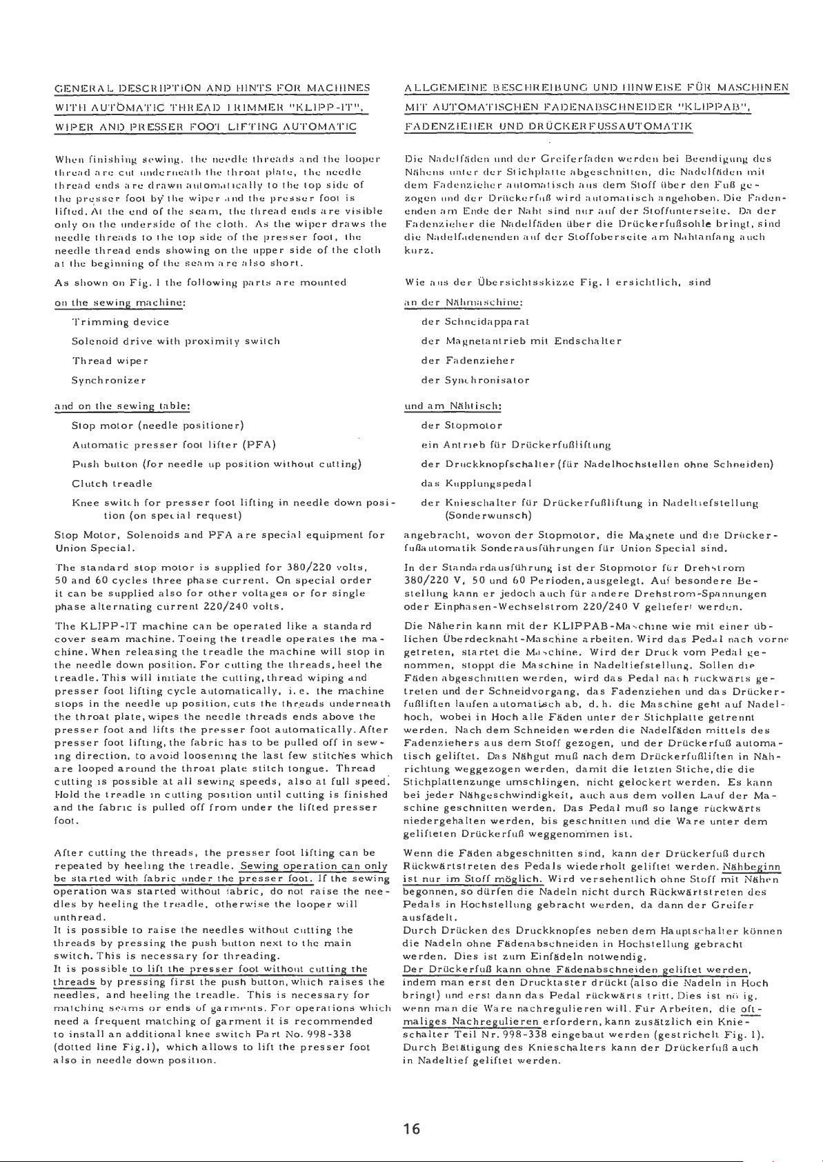
GENlrnAL
WITI-I
WIPEH
Whl.'n
thread
thread
the
lifted.
only
needle
needle
at
the
As
shown
011
the
DESCRIPTION
AUTbll.·IATIC
AND
finishing
:1
re
c11t
ends
presser
;\t
the
on
the
underside
threads
thread
beginning
on
sewing
Trimming
Solenoid
Thread
wiper
Synchronizer
and
on
the
sewing
Stop
motor
Automatic
Push
button
Clutch
treadle
Kn
ee
switch
tion
Stop
Motor,
Union
Specia
The
standard
50
and
60
be
supplied
alternating
KLIPP-IT
seam
When
needle
cycles
down
il
can
phase
The
cover
chine.
the
treadle. This
presser
slops
the
presser
presser
rng
are
culling
Hold
and
foot
in
the
throat
foot
foot
direction,
looped
is
the
treadle
the
fabric
plate,
around
possible
foot.
After
cutting the
repeated
be
operation
dles
started
by
by
with fabric under
was
heeling the
unthread.
It
is
possible
threads
by press
switch. This
It
is
possible
threads
needles,
matching
by
and
s~:lmS
pressing
need a frequent
to
install
(dotted
a
lso
an
line
in
needle down
THHEAD
PRESSER
Sf•wing.
underneath
arc
drawn
fool
by'
the,
encl
of
the
to
the
ends
showing
of
the
Fig. I the
machine:
device
drive
with
table:
(needle
presser
(for
needle
for
presser
(on
spe
Solenoids
I.
stop
motor
three
also
current
machine
machine.
releasing
position.
will
initiate
lifting
needle
cycle
up
wipes the
and
lifts
lifting,
the
to
avo
id
the
at
in
cutting
is
pulled
threads,
heelrng the
started
treadle,
to
raise
ing
Lhe
is necessary
Lo
lift
the
first
heeling
or
enrts
matching
additional
Fig.
I),
which
position
AND
'I
HIMMEH
FOO'I
LIFTING
tilt'
ne,•dle threa
the
throat
a11tom:1t1cally
wiper
,incl Lhe
scam,
the
side
on
the
cloth. As
of
the
of
top
scam a re
following
proximity
positioner)
fool
lifter
up
position
foot
ial
request)
and
PFA
is
supplied
phase
current.
for
other
220/240
can
be
treadle
For
the
operated
the
cutting
cutting,
Toeing
the
automatically,
position,
cuts
needle
the
pr<'sser
fabric
has
loosening the
throat
sew
plate
ing
all
position
off
from
the
presser
treadle.
the
without fabric,
otherwise
the need
push
for
les
button
threading.
presser
the
the
push
treadle. This
of
garinr•nts.
of
garment
knee
swit
allows
.
HINTS
thread
the
upper
also
parts
switch
(PFA)
lifting
are
voltages
volts.
treadle
the
threads
foot
lo
stitch
speeds,
until
under
Sewing
presse
without
foot
bullon,
ch
Part
to
lift
1°0H
"KLIPP-IT",
AUTOMATIC
ds
and
plate,
to
the
JH<!SSer
ends
the
wiper
presser
side
short.
arc
mounted
without
in
needle
special
for
380/220
On
special
or
like a standard
operates
machine
the
threads,
thread
i.e.
the
thr.eads
ends
automatically.
be
pulled
last
few
tongue.
also
culling
the
lifted
foot
lifting
operation
·r
foot.
do
not
the
looper
culling
next
to the
without
which
is
necessary
For
operations
it
is
recommended
No.
the
presser
lvlACIIINES
the
needle
side
foot
are
loop
is
visible
the
top
draws
foot,
the
of
the cloth
culling)
down
equipment
volts,
order
for
single
the
will
heel
wiping
the
machine
underneath
above
off
in
stitch'es
Thread
at
full
is
finished
presser
can
can
If
the
raise
Lhe
will
the
main
cutting
raises
998-338
of
ma-
stop
<ind
the
After
sew-
which
speed
be
only
sewing
nee-
the
for
which
foot
er
the
posi
for
the
the
-
in
:
ALLGEMEINE
MIT
AlJTOMATISCHEN
FADENZIEIIER
Die
Nadclfliden
Nlihens
elem
zogcn
enden
Fadcnzich
die
unter
Faclcnzieher
uncl
cler
am
Ende
er
Naclelf,1clenenden
kurz.
Wie
aus
der
an
der
Nti.hn1aschinc:
der
Schneidapparat
de
r Mal,!net.a
de r Fadenziehe
der
Synchronis
und
am
Nliht
der
Stopmolor
ein
Antr1f'b
der
Druckknopfschalter
das
Kupplungspedal
der
Kni
esc
(Sonderwunsch)
angebrachl,
fuflautomalik
In
der
Standardausfilhrun
380/220
sLellung
oder
Die
lichen
getreten,
nommen,
Faden
tret.en
V,
50 und
kann
Einphasen-Wechselstrom
N!iherin
Oberdecknaht-Masi:hine
start<'t
stoppt
abgeschmtten
und
der
fuflliften laufen
hoch,
wobei
we
rden. Nach
Fadenziehers
tisch
geliflet.
richtung
weggezogen
Stichplattenzunge
bei
jeder
schine
Nahgeschwindigkeit,
geschnitten
niedergehalten
gelifteten
Wenn
die
Dril
Faden
RilckwlirtstreLen
isl
nur
im
begonnen,
Pedals
Stoff
so
in
Hochstellung
ausfadelt.
Durch Drilcken
die
Nadeln
werden.
Der
indem
bringt)
w<>nn
maliges
schalter
Durch
in
Nadeltief
ohne
Dies
Drilckerfufl
man
erst
und
erst
man
die Ware
Nach
Tei!
Betlitigung
geliftet
EIESCIIHEllrnNG
FADlsNA
UND
DRUCKERFUSSAUTOMATIK
11ml
cler
cler
Grciferfaclcn
Stichplatte
automatisch
Drilck,:rfull
clcr
Nahl
die
Nadt:lfliclen
auf
sind
der
Ubersichtsskizze
nt
rieb
mit
r
alo
r
isch:
fUr
Drilckerfuflliftun
haller
filr
Dril
woven
der
Stopmolor, die Mag
Sonderausfilhrungen
g
60
Pe
er
kann
jedoch
die Mas
die Masc
auch
milder
rioden, a usgelegt.
KLlPPAB-Maschine
chinP.,
hine
werden,
Schneidvorgang,
aulomati,,;ch
in
Hoch
alle
dem
aus
Das
dem
Faden
Schneiden
Stoff
N!ihgut
werden,
umschlingen,
werden.
werden,
ckerfu
bis
fl
weggenom·men
abgeschnitten
des
Pedals
moglich. Wird
dilrfen
die
Nadeln
gebracht
des
Druckknopf
Fadenabschneiden
isl
zum
Einfadeln
kann
ohne
den
Drucktaster
dann
das
Pedal
nachreguli
regu
lieren
998-338
des
Knieschalters
we rde
erfordern,
eingebaut
n.
Nr.
UN D
IIINWEISE
BSCl·INEIDEH
wcrclen
abgeschnittcn,
aus
automat.isch
n11r
;lllf
ilber
die
elem
dcr
Drilckerfuflsohle
wire!
Stoffobcrseite
Fig. I ersichtlich,
Ends
cha
lte
r
g
(filr
Nadelhochstellen
cke
rfuflliftung
filr
Union
ist
der
Stopmotor
filr
andere
220/240
arbeiten.
Wire!
in
wird
ab,
der
Nadel!iefstellun
das
das
Fadenziehen
d.
h .
die
unler
der
werden die
gezogen,
mufl
damit
nach
nic
und
dem
die
ht
gelockert
auch aus
Das
Pedal
mull
geschnitten
ist.
sind,
kann
wiederholt
versehentlich
nicht
durch
werden,
es
neben
in
Hoch
notwendig.
F!idenabschneiden
drilckt
ril
ckw
eren
arts
will.
kann
werden
kann der
FUH
MASCI-IINEN
"l<LIPPAEI",
bei
Beenclig11ng
die
Stoff
Naclclfticlcn
ilbcr
den
angehoben.
Furl
Die
Stoff11nterseile.
bring!.,
,1m
Nahtanfang
sind
ohne
Schneiden)
in Nadeltiefstellung
nete
und
d ie
Special
f[Jr Dreh
Auf besonde
DrUc
sind.
~tro
re
Drehslrom-Spannungen
V ge
liefert werdi;n.
wie mil
Wird
das
Dru
c k
Pedal nac h ril
Maschine geht
Stichplalle
Nadelfaden
der
Drilckerfufl
Ped
vom
g.
und
einer
a l
Pedal ge-
Solien
ckwa
das
auf
getrennl
miltels
nach
Drilckerfuflliften
letzten
dem
und
geliflet
dem
(also
Stiche,
werden.
vollen Lauf
so
lange
die
Ware
der
Drilckerfufl
werden.
ohne
Stoff
Rilckwartstr
da
dann der Greifer
Haupts,·halter
ste
llung
gebracht
geliftet
die
Nadeln
tritt.
Dies
Flir
ArbE'iten, die
zuslitzlich
ein
(gestrichelt
DrU
ckerfurJ
die die
Es
der
ruckwarts
unte
N!ihbeginn
mil
elen des
werden,
in
ist
ni,
Knie-:-
Fig
des
rnit
ge-
l~aclen-
Da
clcr
sind
auch
ker-
m
Be
-
Lib-
vorn
die
rts
ge-
Drilcker-
Nadel-
des
automa-
in
Nah-
kann
Ma-
r d e m
durch
N!ihPn
kunn
en
Hoch
ig,
oft-
.
1).
a uc h
e
16
Page 21
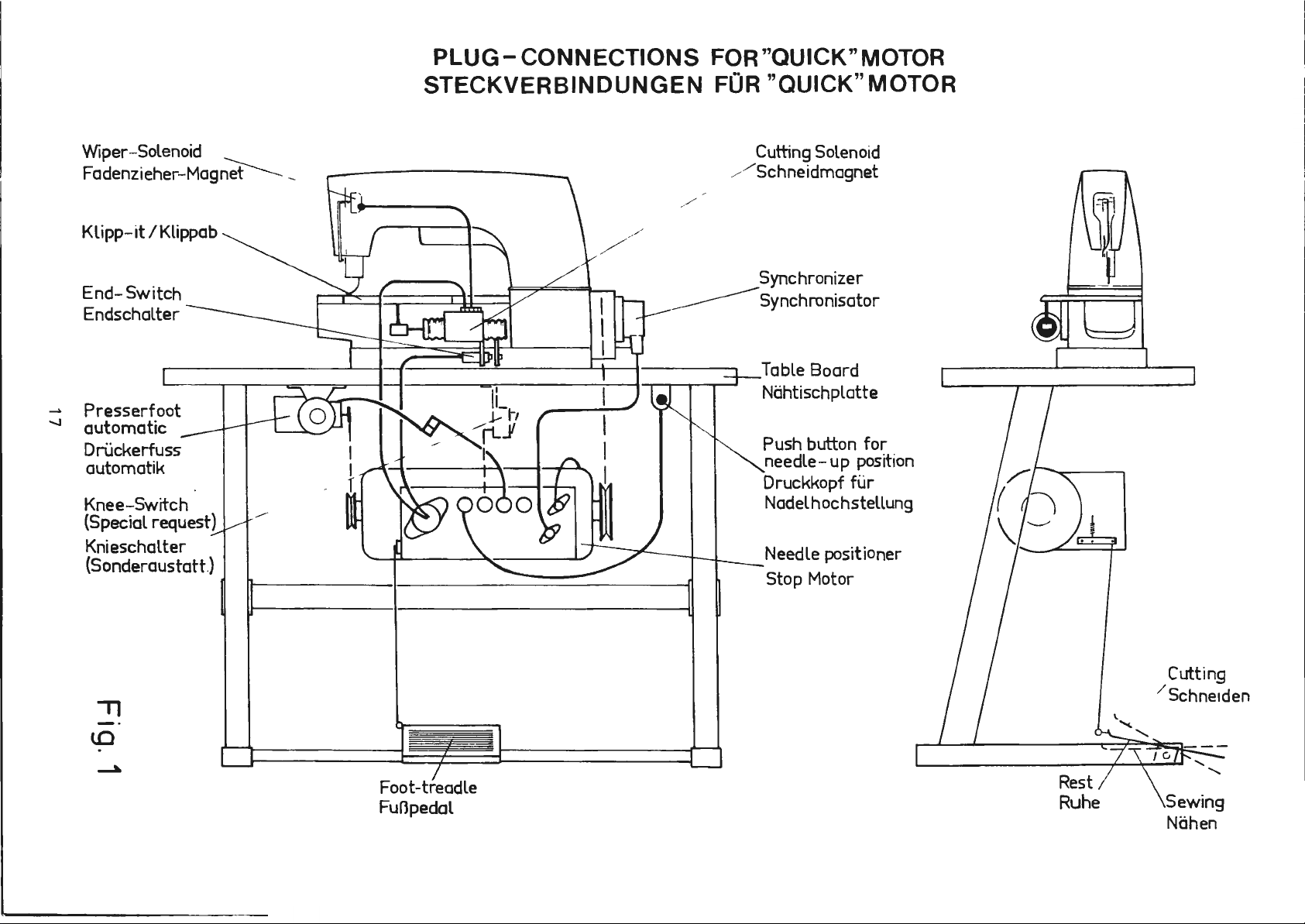
PLUG-
CONNECTIONS
FOR
"QUICK" MOTOR
Wiper-Solenoid
Fadenzieher-Mag~
Klipp-it
End-Switch
Endschalter
_.
Presserfoot
-.J
automatic
Dri.ickerfuss
automatik
Knee-Switch
(Special
Knieschalter
(Sonderaustatt.}
/Klippab
request)
STECKVERBINDUNGEN
FOR
/ Schneidmagnet
"QUICK" MOTOR
Cutting Solenoid
Synchronizer
Synchronisator
Table Board
Nahtischplatte
Push button
needle-up position
Druckkopf
Nadelhochstellung
Needle positioner
Stop Motor
for
fur
71
lO
Foot-treadle
Funpedol
Rest
Ruhe
Cutting
Schneiden
Sewing
Nahen
Page 22

INSTALLING
When
ins
slop
molor
electric equipment
ons and sketches.
ti
sequence.
I. Ins
foot
ma
qui
when
AND
talling a ma
(needle
tall
machine,
lifter acc
hine,
c k
sewing
disconne L plugs.
a
11
plugs a re conne
ADJUSTING
hine
positioner),
please
ording
wilh
refer
Item
s l - 8
synchronizer,
Lo
table
and
Sta
INSTRUCTIONS
KLIPP-IT,
presser
to
the
have
to
motor
rt
led.
I.
lo
motor
All
operate
To
Zum
Fig.
lhread
foot
following
be
followed
and
cables
are
equipped
the mac
Wiper
Fadenz
To
Zum Motor
lifter
between
ieher
Motor
wiper,
and
instru
in
presser
with
c -
hine,
MONTIER -UND
Bille be.,chten
KLIPPAB,
uncl
Eleklrik
Die
Pun
we
rel
I.
lnslallieren
und
zwis
bare
clann
Fadenzieher,
na
kte I - 8
en.
Dr ckerfuflautomatik
hen
Maschine,
Steckverbindungen.
in
Belrieb
EINST
ELLHINWEISE
Sie beim
hfolgende 1-Iinweise,
milssen
Sie
die
wenn
Installieren
Stopmotor,
der
Reihenfolge nac h
Maschine,
nach
Tisch
Nehmen
alle
Ste
einer
Drilckerfuflautomatik
Anleilungen
Synchronisator,
Fig.
I.
und
cker
Aile
Molor
sind
Sie
die
eingesteckt
Maschine
und
ausg
efil
Anschlusse
schnell !Bs -
Maschine
s i
mil
Skizzen.
hrl
Molor
erst
nd.
~ :
SOLENOID
Before
wire,
chine.
Z.
leaving
which
ADJUST
Loosen
on
shaft
(Fig.
a)
b}
DRIVE
has
SOLENOID
nut
(A)
2)
according
Do
solenoid
adjusled
The
(see
the
the
factory,
to
(C,
to
not
be
Fi
connect
, u
nle
according
thread wiper
item
I
I)
solenoid acc
removed
.
obtain
to
before
the
STROKE
Z)
and
move
the desired
the
following table:
the
plug for
ss
the
lo
has
ording
solenoid
before
the cuttin
synchronizer
Fig.
14.
lo
be
it
is
connected
Lo
Fig. I a.
is
secured wit
operating
head (B)
Needle
Nadelabstand
a s
dimension
Dis
8 ga
10
12
16
adjusted
the
required
ta
nee
ga
ga
ga
Fig.
g
is
to
ma-
"a "
h
la
MAGNET
Vor
gesi
Z.
ca.
ca .
ca
ca
Beachten
dem
chert. Bitte
EINSTELLUNG
Nach
(B) au!
das
werden:
Dimension
Ma
16
16 m m
16
.
.
17
ANT
Versand
dem
Mall
ll
mm
mm
mm
Sie:
RIEB
der
"a" (Fi
=
=
wurde
entfernen
Losen
Welle
"a"
1,a
11
/8
5
5/ 8
<./8
4
3/6
a )
Der
Stecker
Anschlull
Synchronisator-Einstellun
angeschlossen
b)
Der Fadenz i
rfolgte r Einstellung(siehe Pun
e
am Mag
werden.
der Mag
Sie den Drahl var
DES MAGN
de r M
utter (C,
(A) entspreche
g.
Z)
na
ch folg
inch
in
ch
inch
4 i
nch
fur
darf
erst
werden.
eher darf
net
nach Fig . I a angesc
net mit ei
ETHUBS
F i g . 2)
nd ver
ender Tabe
den
Schneidmdgnet-
nach
fert1ger
g F i g . 14
e r
st nac h
nem
Bindedrahl
Inbetriebnahme.
kann
de r
s c hoben we
lle
ei n
ges
kl
I
I)
hlo
s s en
Kreuzko pf
rden und
tellt
A
3.
DJUS
Retighten
~
m
otor is
T I
When
hould
s
Fig.3a)
0,
5 - I
nut
T
he
dimension
switched on,
NG THE
the
solenoid
be
a d i
and
mm
(C)
after
THREAD CU
drive
stanc
end
of slot
(0.
020
- 0 .
making th
"b" (Fi
as desc
1s
betwe
(F, Fig
040 inc
i s
g.
2)
is adjusted whe n t
ribed un
TTER
in
its res t
en sho ulde r screw (
. 3
a)
h).
adjustment.
der item
positio
of
approx
n t
i m a
IZ.
her
E,
tely
he
e
Ziehen Sie
Beach
ha
s c
lt.
s te l
EINSTELLUNG
3.
In
Ruhestellung
zwisc
(F, Fig. 3a) ca. 0 , 5 - I
ten
ltetem
hen
die
Sie: Da
Motor, wie unt
Bundschraube
18
Mutter
DES FADENABSCHNEIDERS
(C)
nach
dieser
s M
all
"b" (Fig
des Magnetantriebs
(E ,
mm
. 2)
er
Punkt
Fig. 3a) und dem
betragen
wird
Einstellung wiede
erst
IZ
s o
.
bei ein
beschrieben, ein
il der
Abstand
Schlitzende
r a n.
ge -
ge -
Page 23

Solenoid Drive
Mugnotunlrlob
Boll
Anlj1c
om view
ht
von
untcn
S
oleno
I
I
I
l:lcfore stmh~g
/bcanngsot l
\l>r lnbclricMatvne
C
Logc
Welle olen
r~le
ten
hi>
d,escr
OIi
sha
n
I
I
i
I
I
I
i
{cp)
Fig 2
G H
id
Drive
C
Fig.
ADJ
USTING THE
For adju s
set
Check,
in
end
d im e n s i o n "
.
04 inch
4.
The
ed ge
krife holder
1n
adjusting loo
5 .
Loo
(J,
kni
spring
(0
,
of c
0
3a
THREAD
ting
connecting rod
after
up posi
position,d
low
(X,Fig.4)is parall
line
sen
F i
g.
fe
(T ,
Fig
lam
mak
tion and
a" (Fig
.
e r knife
(K,Fig.
with
e dge (
s e n s c r
screws (La
4) has
to
Fig. 4)
(N,
F ig . 5)
. ~) of lowe r
p s
prrn
CUTTE
loosen
r etai
(II,
F ig .
1nii
this
the
im
g.
low
nsion "a" acc
. 3b) mus t be a t le a s t 1 m m =
(T . F ig .
e l
4) and edge
Z)
of
ew(A,Fig
nd
M,
be S
Pt
by
0, 5 mm (0. 02 0 inc h
lo
low
e r
kmfe
R (Cont
nin
g ring
3a)
adjustm
e r kn
4)
is set correctly, whe n it s 4.
to edge
low
e r knife hol
. 4).Retighten
Fig.
4).
so
tha
t it
kni
fe
(T ) i s
in ue
(G, Fig. 3
as
required.
<>nl
, w i
ife
ord
(Z)
(T ,
1n
th
swun
ing
to
(Y ,
Fig. 4)
o f lower
der.
The upper knife
overlaps
). Set
Fig
. 5) s o
hne
wi t h edge (
d)
a) and
the needl
g
1n
its l
Fig
. 3
o f lo w
knife
For
scre
the low
clamp
that
0
0
0
b.
eft
The
er
w s .
er
P)
es
1s
edge
E IN
STE
Zur
un
d ve r s t
Ub
erpr
den
Unt
(F ig . 3
Da s U
Kante (X, Fig.
m e
ssertrage
messe
Lrn
(A.
Fig.4)
~-
Lcisen
(J ,
Fig
messe
feder (N, Fig
stell
die
Fig.
3b
L L
UNG DES
E in s
tellu
ng lcisen Si e de n Si c
ellen
die Zugstang
ufe
n Si e nac h die
Na d e l n und m d
ermesser
b) mull
nt
r s
ie
bildet.D
Sie
. 4) m ull s o e in
r (T ,
t,
Kan
das
mindestens 1 mm betrage
e r
messe
4) parallel zur
r s (K, Fig. 4 )
m1t der Kante (Z )
1e Emstellu
gemacht.
die
Schrauben (Lund
Fig. 4)
. 5) w i
dall
.i:lte Ka nt e
te (P) d
er
FADENABS
ie
Ma ll "a " n
r (
T,F1g
Z1e he n
um
rd
Klemmfeder
C HNEIDERS
e (H ,
ser
Emstellung bei obenstehen
h n
ke
Endstell
ach
.4)ist
richtig
Kante
isl
und
des Unt
ng wird
Sie
die
gestellt werden. dall
0, 5
mm lib
zum
Untermesser (T,
(0
,
Fig
. 5)
(F o
rtsetzun
herungsring (G, F ig , 3
Fig. 3a) e n
ung
Fig. 3b. Das Mall
(Y ,
die
ermessertragers
nach
Schrauben
M,
Fig
ersc
des
Untermessers
e1ne
tsprechen,d.
eingeschwenk
n •
e t
ngestellt,wenn
Ftg.4)
Kante
(Z )
Lbs
ender
v,ieder
. 4 ).
Das Obermesser
es
hne1
Lrnie
das Unter-
det.
Fig
bilden.
des
des Unter
Die
. 5) so
0
g)
a)
te m
" a "
sein
Unter
e 1
ne
Schrauben
an.
Klemm
ernge
(T ) u
-
e
-
-
-
-
nd
19
Page 24

K y
T O p
Fig . 4
ADJUSTING
Further
(0. 06 -0.
a
nd
front
screw
Set
screw
clamp
I
he It>
11"
11
ppPr kn, f .. (j , Fog.
fh
e 2
spri
ng ( L,
For
making this
TIIE TIIREAD
more
1t
08 1nc h)
edge
F a
g.
(M,
shown
spring
F ig . 6a )
of
of
4).
F i
Lid
(L,
e d a s
,, I
edges
should
be a dis ta nc e
betwe
e n
lamp
g.
4)
1n (Fi
{ I . Fog. 6 ) s ho
mp
adjustment,
lip
s p ri
ng ( ,Fig.
so
that
t he
g.
12)
f,
) b y
0,
s pr1n,-: (N . F og .
must
be a
loosen
of under
looper
.
uld
; ,
nm (0.
lign
e d
of
be
set
6a) ,ind
di
s c
rew"
I,
knife
6),
thread
02 inc
(F
- 2
(T ,1''
ret1ghten
is
to
project
h).
t he
F , F i
g.
(Q,
F ig .
mm
1g.6)
leaf
6a ).
'i)
.
E INS'I ELL
F,•
riwr soil
( I', F I
!(, 6)
I,
- 2
wic
de r
Die SLliraube
fnd e n
w1e
D
ie Blattfeder ( L,
Obermessers
Die K
lemmfedcr
s
oll,•n
c
rfol!(l na
Fig. 5
NG
DES
cler
und
mm
betr.igen,
an.
in (Fig .
be, (FF ,
Ii
Lo
N
T
0.020,nch
05mm
Fig. 6
F A
DENABSCIINEIDERS
Abst,,nd zwis
der
Vorderkante der
ziehen
(M,
F o
g.
4)
w i
12)
gezeigt. geklemmt
F i
g.
(J,
F ig.
(N,
Fig
sen
6)
6) ste he
Fig. 6a)
. 6a ) i n erner
der
Schrauben
he n
S ie d ie Sc
rd
so
soil
n.
und
N
L
der Spi
Klemmfeder
angezogen
0, 5 mm
d ie
Blattfeder
L in
ie ste
(Q, F ig. ; ).
(Fortsetzung)
tze
des
hraub
n (
da/J
w i
rd.
hint
e r
hen.
E i
Untermcsse
(N,
F ig . 6)
L,
F i
g.4)
de r Greifer-
der Spi
tze
( L ,
Fig. 6a
nstellung
rs
de s
)
6.
SETT
6. I Lo~sen
6.
6 . J T he
X"
"
15/32
I
nch
12mm
IN G O F
in d
irection
2 W
hen the needles
lower
(U, Fig. 7) c
s w in g1ng lo
T he dista n
a nd
pornt (V)
r o
obta
a
nd
rotate
(B ) u
po
rnt "V".
LOWER KNI
s crews (R,
kmf.,
low
er kni
orn
wer
Le
1n th,
low
nt
i l t
he low
R e t
X"
"t
15/32 inch
12mm
F E T IP
Fi
g.
7) and
of a rrow
to t
he
fe
t i p and e d g e o f lo
c i
dc
km fe to
b<·t\\e e n the right
is
about 12
s s et11nr,t loo
er
1<ni1·.,
e r :
1ghten s
11
to
are
in t
he
le f
t.
po1n
t (
the
mm
s e n s , re" (W, F , ~ 7)
m»d
rnife
Lip 1s
crew (W).
move
11
T
•
·,p p
V, Fig. ?)
le f
t.
ed ge o f
= I
., r (K) a r
set
g uide
osition,
oper
whe
'i/
32
rnch.
oun
c or r ec. t
(S)
sw1ng
n
looper
d "
'-r
ly
Fig. 7
e \\
a t
6 .
EINST
E L L U NG D
6. I Lo s e n Sie d i e Schrauben
6.
2 SLhwcnk
. 3 Di e Unt
ei
tenfuhru
d ie S
en
Nadeln nach link
(U,F1g. 7)
des
D r
Ka n1e d
Zur E1nstell
und
Sc
hraube
r,
chugen Ste
S
Lhr
S ie
ermesserspit
decken
Untermesse
Pun
kt (
es
Gre
dr
eht den Un
(B ) b
aube (W)
20
Fig.
6a
ER UNTERMESSERSPIT
ng (
das Untermesse
s.
s1ch
r s
V) liegt etwa
1fers
ung
lost
termessertrager
is
die Unt
I lu
ng
wie
de r an.
(R . F ig .
S)
1n P
feil
ze
und
die Gre1ferkante
w!ihrend
1m
Punkt (V,
12
entfernt.
bei
mm
man die Schrau
ermesserspitze
" V"
steht.
r 1Lht u
r b
des
F ig.
vo r der recht
Z1ehen
Z E
7)
und sch1
ng nach "T" .
ei
o b e
nstehende n
Ernschwenke
7).
be
(W , Fig. 7 )
(K ) nm
1n
S1e
e be n Si c
ns
en
die
der
di e
Page 25

6.
SE
6. 4 Swing
Fig.8 Fig.9
T T ING
OF
LOWER
KLIPP
point
(V,
d irec
tion
lower knife
flecting it.
The
height
(Fig.9) can
ering
(S,
F i
g.
(K,
F i
g.
Retighten
Note:Every time the s c
~djust
to
readju
T U
s
F i
g.
or
or
or
raising gui
8)
is
8)
and
screws
i
ng
s t the
arrow
holder
be
- IT until the low
7).
the
positioned
the
E
KNI
F E T
Now
move
11 11
to
(K)
at poi
lower
adjust
spring
guide
knife abov
ed simultaneously
de
(S,
betwe
(E,
F i g. 7) .
rew
lower
(S , F ig . 7).
Fig.
knife
(R,
s
IP (Continu
e r knif
guid
e fS ,
unt
il
it
11
nt 11D
e looper
Fig.
8),
e n
low
8).
(W, Fig
tip,
V W
ed )
e ti p reach
Fig. 7)
hout de
by
nife
is
ne c e
in
the
-
blade
lo w -
de
hold
ssary
onta c t s
wi t
a s the gu i
e r k
.7)is loosened
it
e s
6.
e r
EINSTELLUNG
6. 4
Schwenk
spltze
im
die
Seitenfilhrung (S,
bis
sie
zu
G
durch
des
stellt (Fig.9
Untermessertr!lger
liegt.
Beachten Sie
zum
Seite
im
drilcken, anliegt.
leichteitig
Ver
Unte rm
Ziehen
Einstellen
nfilhrung (S,
o+0.004
o+,
DE R UN
e n Sic de n
Punkt
Punk
t 11D
wird
schieb
e n
ess
e r s
),
da d ie
Sie
:Nach jedem
der
inch
mm
TERMESSE
KLIPPA
(V, Fig. 7) s
Fig.
11
am Unterme
mil
der Seitenfilhrung (S,
nach obe n ode r
Uber
Seitenfilhrung(S,Fig.8)zwischen
(K, Fig.
di e
Schrauben (R, Fig.
Untermesserspitz
Fig.
7)
RSPITZE
B e
in
bis die U
teht. Jetzt schieben
7)
in
P fe
ilrichtun
s s e
de m Gre
Ltlsen
neu
iferr
8)
und
de r
eingestellt
unt
Feder
Schraube
(Fortselzung)
ntermesser
rtr!lger
e n , d ie Htlhe
ilc
ken
(E,
7)
wieder
e,
mull
werden.
ein
(K),
F i
ge -
g.
(W,
die
Sie
ohn
8)
an.
Fig.
g nach 11C "
Fig. 8),
-
e
7)
7.
The
6
is a basic
to
F i
the
looper
back,
(V
, Fi
Fi
g. I
The
after bei
can
8.
THREAD
ADJUSTMENTS
8. I
8. 2
8. 3
8. 4
Fig. 10
setting of
g.
l 0
needle
thread
the
g.
I)
loop
be
adjusted
Loosen
located
(A, Fig.
R
Adjust
turning eccentr
discs are
begins. The
f
reely
Adjust
that the
st
that
the fabric,
Adjust
that
1t has
Note: The
~
the
adjustment.
and
Fig.
thread
at edge (S).
looper
11)
and
and
drawn
e r
thread must
ng ·severed. The
PULL-OFF
the
at
13)
etighten
the tension dis c s
between
needle
needle th read end
art
sew
the
need
looper thread p
the
loop
been severe
c ut
trng
low
e r
knife
ti p a s descri
It
I 1.
loops(T
thread
the needle
back
with screw
clamp screw
the
in a horizontal
clamp
open
te n s1
ing immed1a telly on the
le
are
e r
thr
ea d
th e th
must be
The
low
and
As the
must
threads
to
the
be cla
tension
(M, Fig.
AND
TENSION
r e
ar
of the
scr
ew .
ic
(D, Fig.
ed a s s
oon
on
disc separator
tension discs witho
thread pull-off
thread end
a s short
ull-off
thread
is cla m
d.
pull-off
rea
d s .
rechecked
e r knife
U,Fi
g. I 0)a
low
be caug
ht
by
upper
mped
as
of
4).
in
clamp
machine
position.
eparator
13)
so
a s
the
hoo
s a r e long
,;; vis
ib le
a s po
ssible .
ho ok (F ,
ped sec urely aft
hook s must mcive
Fig.
11
bed
in
item
must
e r k
cutting
knife.
the
RELEASE
that the
cutt
ks (E , Fig. 13) s o
according
pass
nd
deflect the
nife swings
by
cutting edge
edge
shown
in
clamp
lever
(B,
and
set
(C, Fig
.13)
ten
in g
process
should
ut
bi nd i n
enou
next stitch
on the
fac
Fig
. 13 ) s o
through
(W,
Fig. 12,
sprin
F i g.13)
lever
by
s i
move
g.
gh
a nd
e of
freel
on
to
er
---
--,
Fig.12
7.
Die
Einstellung der
eine
Grundeinstellun
Fi
g. 11 ilberprilft
Nadelfadenschleifen
di e
und
an
de r
Zurilckschwenken
faden
der
Schneide (W,Fig,}
g
Nach
g
ezeigt geklemmt
kann
8.
EINSTELLUNG
UND
8. I Ltlsen Si e
8. 2
8. 3 Stell
8. 4 Ste
y
Kante
van
de r
dem Schneiden
m it
der
DES
F ADENABZUG
Fig
. 13 )
den Hebel
Sie die
Stell
e n Sie die Fade
dur
c h Verdrehen
daJl die Faden spa~nungsschei
vor
ga n
ges
leiste m uJl zwische n den
eh
e n u
g
en
ei
n, dall bei fr e ie n Nad e lfade nende n
beginn ga ra nt i e r t
Obe r
seite des Sto
li
en Sie
ei n ,
da
Jl der G rei!e
fe st
gek
le m m t wi rd.
eachte n
B
wl!.hre
nd
Untermesser
g.
Sie
werden.
(T
(S)
den
Greiferfaden
des
Schneide (V. Fig.
Schraube
auf der R il
Kl emms c h
nd darf nicht
Sie die
de s S
Untermesser
l)zum
muJl
der
sein.
Di e Spannung der Klem
(M, Fig.
DER FADENS
S
die
Klemmschraube
(A, Fig. 13)
Ste die
ckse
raub
nspannungsoffnungsl
de r
ge offn
et werden.Die
Nadelfad
ist und
ffe s s
den Gre1ferfadenabzugshaken
rfaden beim Abs
Frei
chneidens
s pi
mull
entsprechend Fig.
Das
Unte
und
in
Exzenter
klemme
gli
r m
U, Fig.
s m Us s e n de r G r eife
11)
und
Oberm
esse
Gre
iferfaden wie
4)
PA NN
ite d e r Ma schi
waa
gr ec h
e wie de r a n .
be n b
Fadenspannungsscheiben
n.
ena
bz u
nur
kurze
ichtbar
ngigkei
.
tze
nach
Punkt
.6
esse
10) hindu
ablenken.
die Nadelflld
r gezoge n we r d
eingestellt werden.
UNGS
F REIGA
im Klemmhe
te Stellun
hul s e (D,
ei Beginn de
F adens
gshaken (E,
ein sofort1ge
F a de
sind
.
c hne1d
t d
er Fad
IO
r m u
Jl durc
rch
ge h
Be 1m
en von
in F
ig.
mfed
BE
bel
ne und bring
g.
Zi e he n
eis
te
(C ,
Fig
. 13) s o ,
pannungstlffnu
Fig. 13
nenden
(F ,Fig
en
sicher
enabzugshaken
ist
und
h
en
r-
n.
12
er
(B,
en
Fig.13)
s Sc hneid-
ngs -
fre
i -
) s o
r Nl!.h-
auf
der
.1 3 ) s o
21
Page 26

\
j
---
--
·-io
I ' ,
I
!-----~·'
®
, ,
tlr;j__
· ,
-tt:.
I I
I'-· I
/
~l(l
...............
' ·
,1c
ADJU
STING
Be
fore
desired
Holate
position
protecti
se
t s
cre
(C, Fig
on
the center
Now
rota
a clJuSt t he m a g ne t carri
that
iL i s
(D,
F ig .
fine adj u s t
to
Toe tre
to p s
t
he
posit
Fi
g.
14)
Heel
trea
s pe e d
Correct,
No
w t i ghte n
protective cap
Before
is
attached with
synch
ron
rotecto
p
getting
Not
e :
The
nizer befo
OF
SYNCHRONIZER
start
ing opl!
po s
iti
s e wi n g m a c
(ob
s e r ve d i r e c
ve c
.ip
w
(B,
. 14 )
with the r
te the machine
lo
cat
14)
. No w s
adle
in nee
dle
ion
(red mag
dle:The mac h i
(cutting speed)
if
· hi
pping the machine,
izer (Fig.14).This gu
r.
It
th e
fingers
guard
re
ration
on
o n
the
hin
(A , F i g .
F i
g.
14)
o f t he ba
ed
on the c e
wit
men
t.
and
rel
ease
down positio
by
readju
net).
necessary,
set sere\\
on
synchronizer.
two
prevents
caught
ring must
starling to
·'"""'
......
1', '-,
,,.
,v· , ·
,· ...
,h
• \
' I
.J . :
----
-
Fig.
13
of
the
synchr
e m a n
tion
14)
and turn the magnet
ed mag
ll
bearing ret
e r w
c h
: T he
s ti n g t he mag
ne
in
as
(B, Fig.
screws part
the operat
operate
motor,
onize
r.
ually
into
of
rot
from synchronizer,
in
on
position
to
in
be att
a t i
net
so
that
ainer (D, Fig.
needle up
ith
the yellow
nter
of
Llw ba
the
motor
machine
n.
Correct,
net
s a t the
the
needle
a b
ove
(yellow mag
14) and repl c
a guar d
No.
a r d serves as a finger
or
from acciden
the han
dwheel.
ached to the
the
machine.
----
adju
needle
on).
Remove
carrier
iL
is
po s
ition
magnet
ll beari
and procee
starts, then
if
nece
carrier
prescr i be d
up position.
part
No.
9 5365
\
\
\
\
s t
the
down
loosen
localed
and
s s
ary,
net).
34 3
21
to the
tall
synchro-
I
14)
so
ng
(C,
d
B ,
y
Guard
31.
321
Schulzrmg
B
31. 3 21
8
_
60
60 Hz-
SO
50 Hz-
C¼'cle
Cycle
Te1lung
Grodool1on
Te1lung
Graduation
- c
\
2x
Screw 95365
2x
Schroube 95365
10
. E
INSTELLUNG
Vor
lnbetriebnahme
Lionen
a m
Di e N.-hmaschine
drehl
(beachlen
vom
Synchronisalor
Sie
die
.
lmpulsgeber
dieser
Nun
stellen
d
Jetzl
vorgenom
Tr
D
Kor
des lmpulsgebers (C, Fig .
Treten Sie das
chriebener
Stell
(g e
14)
Synch
An
ein
9
F i ng
s
cheibe gegriffen
Beachten Sie: Der
t
riebnahme der
Klemmschraube
auf
drehen
de n
ieser auf
kann
eten
Sie das
er
Motor
r i gieren
u ng.Korr i g
lber
Ma g ne
£est und
r o
nis
de n
Synch
Schutzri
53
65 a ng e s
erschutz. Er
DES
SYNCIIRONISATORS
Synchronisalor
(C,
der
Sie
lmpulsgeber
der
der
m e n w e
lli
ufl
Sie,
Drehza
setzen
a t o
r o n
ng Teilnr. 343
chraubt (Fig .
des
wird
Sie die
die
Fig.
14)
Mille
des
di e
Maschine
Mille des
Motor
rden.
Pedal vorw
an
und
wenn
Pedal
hl (Sc hneiddrehzahl)
ier
e n S
t).
Nun
die
r.
isa
to r w
ve r
werden
Schutz
Maschine
van
richti
eingeschaltel und
nciti
r U
ckwlirts:D r Mo
ie,
ziehen
hindert, dafl
'-.......~
~ D
Motors sind
einzustellen.
Hand
in
Nadel-Tiefstellun
ge
Schutzkappe
mil
Kugell
Kugellagerhalter
brem
wenn
Schutzkappe
ird
ring mu
Drehrichtung).
(B,
Fig.
14)
dem
roten Mag
a g
erhalters
in
Nadelhochstellun
mil
dem gelben
li r
ts
und
st
i n Na
g, d i e Sle
14) (rat
var dem Versand
21
14)
kann.
montie
llun
er Mag
noti
g , w i e z
Sie die Kl
B m i l
. Di
eser
i n
ll
i n j
rl sein.
A
die gewUns hten
(A, Fig
und
die Fein
!assen s w1eder
del-T
g d u
to r lli uft
emmschrau
(A, F ig . 14 )
zwei Schraub e n
Sch
die
edem Fa
Zieh
.14)
drehen
net).
i n di e Na
,1b,
Sie
net
so, cla
(D,Fig.14)
Ma g
net so, d
s (D
,Fig.14)
einstellun
1ef
-Stellung
rch
Nachdrehen
uvor beschrie
de r
ut z r in g
Han
d r
adneme
ll
va r l
g
mit
del-Hoc
auf
dient
Posi-
i;
ge
•
en
Sie
li.isen
den
fl
s le
ht.
und
ver-
af3
steht.
g
la s :
ab.
vorge-
h -
be
be
(B,
Fi
den
Maschine
Teilnr.
a ls
n-
nbe
-
g.
1 1. E
I.
A
DJUSTI
1
1.
NG
THREAD
1
Keep
wiper disc
Se w
and cul
pre
sser foot.
N
ow
a c t ua
eads mus
t r
(A,
Fig
. 15) to
When the hook (A, F
catch
the needle thre
On
its
trav
t
he nee
dle point
T h
is adjust
(A ,
Fig. 17).
WIPER
thread
te the
t be
wards th
el t
he hook sho
m nt is
onn
ected
s w i
wip
e r m a nually.
deflec
e o p
ig.
a d s .
s o r th e
acco
and swit
th fabr
ted
16)
presser foot.
m plished
ic
by th e wip
erator.
r e t u
rns
uld
not i
c h
on
motor.
unde
r t
The need
er
ho ok
it
m u
nfer
e wi
with scre
he
le
st
th
w s
INSTELLUNG DES
11. 1
Sch
alten
zi
eher noch
und
s c h neiden Sie
N
un
ein
. D abei m tisse n d i e Nade
Fig. 15
B i m
lfliden vom Hake n (A.Fig . 16 )
de
Der Haken
berUhren
Die
Einstellung wir d m it d
gema ht.
22
sc h
wenken
) z
Zu
F ADENZ IEHERS
Sie
de n
Moto
mcht ang
i m
Sie den Fadenzie h
ur
Nlih
erin hin
rti
c k
schwenken des
darf
auf seiner Bahn die Nadelspit
oder geg
en die Dnickerfull
r e
in, dab
e s chlo s s e n s ein. N
Sto
ff.
, a bgel
ei
darf
erhaken van Ha nd
lfiide
n vo m H
enkt wer
Hakens
en Schrauben
mUssen die Na
mitgenommen werden.
s ohle s
der Fad e n -
ii.hen
S1e
aken
.
Fig
(A,
zen
tollen
. 1
den
(A ,
7)
ni c
-
ht
.
Page 27

Fig. 15
Fig.16
,,,.,.""
.
"-
.......
_
....
..............
.........
___
",
/
•y,
l
I ·,
L,.-(
I
I
I
'
I I
I I
I I
I I
I )
I I
_,;,
I
I
....
/ /
~
-,,
_
F
ig.18
Fig.19
11. 2 The
ADJUSTING
12
. 1
12. 2 Switch
12. 3 Toe
12
. 4
12. 5 Operate
12. 6 Toe the trea
12. 7 Swing cutt
12 . 8
wiper
should
the
lever
end
that
the
Adjust stop
contacts
position
of
Connect
assembly
cover
arrow
thread
Set
"b"
nent
(preliminary
Release
from
tion.
keep
not
before
must start to
This mot
approxi
be
Chan
i
be
hook
s c
rew
(G,Fig.
(L,Fig.
are
even.
the
clamp
stop
Retighten
Before
tem
of
the
left
wiper
removing
must
direction
wiper
OF
proximity
(Fig.2)between
magnet
on
treadle
motor
the
it
in
rotate.
it
mate
fore the
ge dist
12 .
!,
is
it,
is
treadle
thi
in g sole
or pull
hook
(B,Fig.17)
approximately
in
its
right
l7)and
17) until
Retighten
lever
the
wiper
scr
e w
(G).
(N, Fig.
approximately
needle
by
be
PROXIMITY
is a
motor.
(the
cuttin
dl e
s po
reaches
ly
end positi
ance
according
17)
when
the
(Fig.
to cutting
the
removin
removed
Fig.
connector.
switch
proximity switch
pproximately
adjustment).
motor starts to
in rest position,
pulley
and
g sole
in sewin
sit
ion. The
noid
its end p os ition
rota
te
e y
restart
0,
3 -
"b" (Fig. 2), des
and
clamp
even
at
end
position.For
screw
(J,
the
hook
screw
(L)
solenoid
head
19). To
(D,Fig.2)
a ga i
0, 5 mm
on
ly,
(J).
contacts
is
so
that the
wiper
hook
3
mm = 1/8
18).
solenoid according to Fig. 1
cover,
screw
horizontally
avoid
SWITCH
0, 5 mm
rotat
e needle
noi
d m anua
g posit i
mot
back
by
n.
ing
point must be
= .
of
the
c uttin g s o
if
ne
cessary.
spring(C,Fig.17)
point
(F,Fig.17) when
Fig.17)and
end
and
Stop
(I-I,Fig. l 7)is
the
stop
effective
clamp
in
its
separate
(D,Fig.17).
to
damaging
(D,
FIG.
so
that
the distanc
and
run).
remo
s i n
lly.
on
(
Fig
o r
pulley should
hand slowl
the mot
012
- .
cribed
adjusting
the
inch
the
2)
the
::.
02
ve
.
02 inc
lenoid
unde
turn
clamp
(H)
just
.
lever
left
end
left
wiper
The head
left
the
pe rma -
inch
V-belt
up posi
I) and
y. Just
or
h
.
r
A
clamp
before
(L)
(in
e
-
pulle
loosen
sprin
set
a.
y
11
. 2 De r
Fig.17)
Punkt (F,
Sie
g
so
12.
EINSTELLUNG
12. l Der
12. 2 Schalten
12.
12. 4 Bringen Sie das P e
12. 5 Schwenken
12.
12
. 7 Schwe nk
12
. 8
die
und
Klemmfederende
Sc
hraube
eingestellt,
im
Magnet
Schraube
Der
hebel
seiner
linken
Schliellen
Schneidmagneten
Bevor
nehmen,
Schraube
waagrecht
werden,
besch
dall
der Abs
Dauermagnet ca.
3 T
ret
Keilriemen
de
Na
6 T r
ete n Sie
und halt
scheibe darf
z u r il
riemenschei
Dies
mull ca.0,
magneten lieg e
Der unt
Bedar{
23
Fadenzieherhaken
sollen
in
Fig.17)
Schraube
drehen
Endschalter
e n
ck, Kurz
er Wiedereinschaltepunkt
(J)
(G)
Anschlag
(L)an
linken
Nadel
Sie
Sie
den
mull
(O,Fi
damit
ll.digt
DES
Sie
Sie
l n
in Hoch
en Sie
en Sie den
3 -
er
12.
ents
den
Pratzhebel
wieder
dall
der
am
Anschlag
wieder
(N,Fig.17)wird
ihm
anschlll.gt
Endstellung
hat
jetzt
Kopfdeckel
der
g. l
nach
links(in
der
wird.
ENDSCHALTERS
tand
den
das
Pedal
van
de r
s t
Sie
den Klipp
da s P
es
s ic h ni
var der
be wied
0,
5 m m var
n.
l e
pr eche
(B,Fig.17)und
der
rechten
in
etwa
(G,
(Fig.
an.
Fadenzieher
7)getrennt
(D,F
"b" (Fig.2) z
Motor
ellun
eda
in
ing
bilndig
Fig.17)
gleich
hoch
an.
Der
Pratzhebel
(H)
an.
18).
den
Fadenzieher
Pfeilrichtung,Fig.19)
Steckanschlull
ig .
2) wird
0, 5 mm
ein.
nach
dal
in
Ruhestellun
Motorscheibe
g.
a b
l nach
die
s e r Stellung. Die
cht dre
Klippabmagneten
Endstellung
e r
drehen
e s t ellte
nd
z u 11.ndern.
die
Endstellung
sein.
und
die· Schraube
(L,Fig.17)
stehen.
Anschlag
(L)
anschl
so
eingestellt,dall
wenn
der
einen
Abstand
links
am
<lurch
werden.Der
des Fadenzieher
(D,
vorl
wischen
ist.
vorne
(der
ab und
magneten
vor
ne in
hen
.
mull
.
der Motorriemenscheibe
der
E n
dstellung de
Ab s t
and "b" (F
Klemmfeder
des
Zur
Einstellung
bis
Hakenende
Ziehen
kurz
ll.
gt.
Fadenzieherhaken
nach Fig. 1 a
Maschinenarm
Entfernen
FIG.
ll.ufig
g,
van Hand ein
Nll.hstellung (Fig.
langsam
Sie
(H,Fig.17)
var
dem
Ziehen
van
Kopfdeckel
2)
s o eingest
Endschalter
Motor 111.uft
nehmen
d r e
Moto
sich
di e Motor-
ig
.
Hakens
(J,Fig.17)
die
wird
Anschlag
Sie
die
der
ca.3
mm
am
ab-
der
abgezogen
s'
und
).
Sie
den
hen
Sie
.
rrieme
van
Hand
s Klippa
2) ist bei
(C,
im
lfisen
und
so
Pratz-
in
zur
mull
nicht
ellt,
di e
I)
n-
b-
Page 28

13efore
tirneR,
whi<:h
Hight:
Left.
All
Thre,,rl
Thrc•,,d
Looper
lhe
If,
nwy
need!.!
needle
lll!ed
le
twisting.,
twisting .,round
misses
presser
Looper
when
seams
Both
but
misses
operator
or
needle
brushed
Needles
Lh
read
side
Bevor
die
neu
eingestelll
mit
nillzlichen
Rechte
Linke
Alie
Der
rechle
Nadelschlinge
Nadelschlinge
Nadelschlingen
Faden
Nadel
Der Faden
l•n
ke
Nadel
Der
Greifer
schlingen
furl
Uber
cine
Der
Greifer
fadenschlinge
lrerin
versucht
de
der
Kleidungsstucke
Heide
Nadelfadenschling
gut
gebild
gestreifl
Die
Nadeln
dendreieck
ein
rna,:hinu
howcv•!r,
provu
Co
loop
loops
foot
ends
loops
oul
miss
Maschine
Storungen
verd
verdrehl
nimmt
nicht
nimmt
et,
und
slechen
auf
beneficial
ncl
loop
too
t.oo
Loo
round
both
coming
1s
righl
is I rying
of
g.1rmenls
formed
of
the
l
ria
ngl e on
werden
1-Iinweisen
rehl
auf,wenn
Qtlernaht
nicht
den
aber
vom
nicht
aufgenommen
der
!,:fl
lhu
tht! n1;1l.:hi1H! h;1s bt.+t•11
to
it
ion
f;11;tory
ii
you.
111111111
small
small
righl
JH'edJe
lefl
needle
need
le
loops as
off
,,
SC,lll'l
needle
loop
Lo
match
properly
way
of
looper
looper
die
zu
zu
sind
sich
sich
beide
Fabrik
murJ
klein
der
verlassen
(z.
B.
nach
.
klein
zu
klein
um
die
um
die
Nadelfaden-
Drlicker-
nach
geht
die
rechle
wenn'
oder
Nadel-
die
das
Na-
En-
auf,
Saum
auszurichten
e n
werd
in
das
e n
nur
Fa-
seile
Greifer
nicht
Greife rrlic:k
w,111
,1CI
J11
Htud
i-1•,,rJj11stf•d
,111d
o111cl
SK.IPPED
C"
'l',d<c-11p
Ncrcll,:
g11/l
rrl,
and
Needle thread
gu.1
rel,
a ncl
Needl
e s
needle
loop
Large
needle
Front:
needle
Lh
read
pushing
Material
Lhe
cross
Needle
may
be
matching
Needle
Looper
ing a good l ria
The
operator
needles
hat,
einer
wurde
Reparalur)
t.Jt
wi
rt.:
thrrad
coll.,psing
loop
do
not
properly
loop
guard
is
nol
seam
clefleclcd
holding
sea
ms
bar
set
lhread
pulls
glance
sie
pindwd
pinched
thread
too
Loo
ngle
off
FEHLSTICHE
Ursache
Nadelfadenabzugsbiigel
Nadelfaden
schlag
durch
eingcklemml
Schlingenbildung
Nadelfaden
anschlag
wird
Die Nadel
um
eine
(zu
kleiner
Die
Nadelfadenschlinge
Der
Nadclfaden,
durch
vordere
durch
eingeklemmt
die
Nadel
geht
nicht genug
passende
Schlingenhub)
Nadelanschlag
drilckt
ohr
Das
Nahgut
niede
Die
Nadel
die
d;is
den
Saum
stUckes
Die
Nadelstange
Der Gre
bildel
Die
Naherin
oder
cine
Quernaht
rgehallen
wird
Nahgut
oder
richtel
iferfaden
sic
h
die
Nadeln
wird
und
zur
zuriickhalt,
das
in
ke
ziehl
durchstechen
i11Hpc,1cd
is
nol.
SI'!
l'CIIES
II s (' s
•t
too low
by
needle
by r ront
pulled
back
rise
enough
pinching
thru
he
Id
clown
;,nd
is
flagging
toward
back
on
or
ends
high
loose,
back
when
pr/izise
und
nliht
den
hint
und
den
vorderen
nnd
zurilckgezogen
Schlinge
ihn
durch
nicht
var
flalterl
Naherin
Ende
stehl
zu
isl
zu
gutes
Fadendreieck
das
Nahgut
weichen
to
giv,· yo11
s,•wing
l"<'d
prc:,perly
r
nPcdlc•
loop
nec•d I e
lhru
to
form
needl
needle
in f ronl
operator
material
of
garment
and
nol
on
material,
coming
eingeslellt
nichl
zufriedenstellend,
steht
zu
ticf
eren Nadelan-
ve
rhinde
Nadel-
Schlinge
nach
zu
bilclen
isl
zu
grorJ
klemmt
das
der
Qucrnaht
hingezogen,
wahrend
des
Kleidungs
hoch
los
e,
dadurch
nach
aus,
wenn
needl
e
eye
of
who
while
mak-
on
rt
oben,
Nadel-
hinten,
1111) utmo
e
or
a
seam
und
die
den
Sie
-
sie
s t s;,ti6foction
,
se
e
the
R.,i11,•
Lower
Lower
Drop
loop
rea
dj11s
sa
ry
Lower
slightly,
Low
or
increase
See
is
sticking
Do
not
material
Lower
Increase
Do
not
Check
konlrolliert.
Stellen
ein
wenig
Hinteren
stellen
Vorderen
stellen
Stellen
liefer
abstand
tieren
stangenhohe
Stellen
Nadel
die
Fadenspannung
Stellen
etwa s tiefe
Fadenspannung
Schau
stange
Das
ilbermarlig
Stell
Verstarken
ecke
Ziehen
Prilfen
Spitzen
c
h:lrt
t.ake-up
re,, r nerd
front
needle
e r g;
I.
t.,ke-up
e r
front
if
presser
hold
needle
pull
needles
sehen
Sie
Sie
oder
Sie,
Sie
ctwas
Sie
en
Sie
oder
Nahgut
e n
Sie
Sie
Sie
um
.,nd
below
for
Cur
us
wire
le
g11a
needle
b,1r sli
I/64
I e
for
ghtly
to
bar
Lhe
111g
need
or
e
increase
needle
thread
back
looper
materi
Wenn
Sic
bar
excessively
bar
slightly
thread
a l
for
burr
die
Maschine
in
folgender
tension
or
Behebung
den
NadelfadenabzugsbUgel
nach
oben
Nadelanschlag
Nadelanschlag
die
Nadelstange
vergrdrlern
0,4
bis
wenn
erforderlich,
nach
den
Fadenabzug
liefer,
den
vorderen
r,
oder
verstarken
nach
ob
der
Drlickerfull
darf
beim
zuri.lckgehalten
die
Nadelstange
Sie
die
Greiferfadendrei-
da s Nahgul
die
Nadeln
d11rnb
s11ggcs I
slightly
rel
guard
or
1/32
height
righl
thread
guard
presser
lension
al
the
elwas
etwas
Sie
0,8
oder
Nadelanschlag
die
Drilckerfull-
Richten
nicht
auf
i li
ty
"'
,,II
1.un
s
slightly
slightly
incre,,se
inch
.,ncl
if
nece
need
I e
tension
slightly,
fool
on
back.
jedoch
Tabell
liefer
liefer
ein
wenig
den
Greifer-
und
mm
die
filr
die
verstarken
Sie
klemmt
nicht
werden
elwas
nach
hinten.
beschadigte
s -
e
jus-
Nadel-
rechte
S1e
die
tiefer
24
Page 29

EXPLODED
VIEWS
AND
DESCRIPTION
EXP
LOS
TE
ILE-BESCH
IONS Z EIC
UND
RE I BUNGE
OF
PARTS
HNU
NGE
N
N
25
Page 30

22C
22
30
Torque:
Drehmoment:
Pos. Nm
I
2,0+0.2 17+
ll
3,0
lbfin
2
26
Page 31

Ref.
No.
Pos.Nr.
2
3
4
5
6
7
8
10
11
12
13
14
I 5
16
17
18
19
20
21
22
22A
22
22
C
22
23
24
25
26
27
28
29
30
31
32
33
34
34A
35
36
37
38
39
40
4 1
42
4 3
44
P,,
T .. d N
34335
')99 - 211 E
13
3•
22874
999
99'
993•17
34336
34336
34 3
34336
34336
34390
3
4390
34390
4342
3
34342
22894
22565
%841
G
216
34393
34393
R
3
4393
3
4393
D
9
96390
9376
34390
')66
34390
22569
%390
999-216
34390
34390
34383
999-216
96528
51257
999-212-348
56 3
- 11 4 E
999-212-0
22894
5
6382
22733
999-212-520
rl No.
36
-2 I I A
) -
211
36
57 X
776
58
54
98
r.
F
G
13
F
D
E
A
D
A
B
AD
C
Q
S
T
R
B
C
B
E
E
F
A
AA
C
E
M
E
BUSIIINGS AND
3UC
I IS
rew
ng le
for
lefl,
g m i
lefL.
rear,
front,
e
S,•,d R
ge
l Ring
for
lower,
r w
EN UNI) V
11
Sl<•
cvc
fl.
for
for
D,ff.
for
hl,
for
for
clclle,
for
for
for
rension Relea
ing
w
for
for
P resser
esser Bar
r, for N
1
<' R C r i p l i O
Ho lt
Ring
" O " -
Prt.!ssurc
Sc r
ew
"O"
- R ing
"O"
,
H
52
- H, ng
Plug
-S c
Bush,
Bushing right,
Hushing
l-lusl11ng
Bushing rig
Hushing lefl,
Bushin
Bushing
Bushing
Bushing
S
rcw
Sc
rew
Pin
Bushing for
Plug
Flang
Oil
Flan
Knurled Nut
Ga
ske
Plug Scre
Bushing for Crank Shaft As
Pin
Bushing right,
Sc r e w
Gasket
Plu
g
Bush
i n g right,
Bushing left,
Bushing
Plu
g
Stop
Pin
B
ush
i ng for P r
Plu
g
Bu
s hi ng
Bushing uppe
Plu
g
S
cre
w
G
as
ket
Plug Se
Plu
g
S
cre
w
EHSCI
Feed Rocker Sh11
Feed Roc
-Feed
Feed
Lift
Feed
Main
Shafl
for Mai n
Cranks
Looper
Looper
for
Crankshaft
Pull
e r
Pull
e r Shaf
Fool Lifter
fo r N
eed
eedle
IIEDENE
ker
Change
Shaft
Li ft
Shaft
Shaft
ha
fl
Drive Sha
Drive Sha
s e L
s e
Shaft
t
le
Ba r
Bar
MIS
CEL
fl
Shaft
ever Shaft
mbly
L e v
LANEOUS
VER
fl
ft
er
27
PLU
GS
SCI
ILUSS-STOPFEN
Bcschrcibung
Bolzen
Dichtungs
Druckh,llse
S
hraube
Die htungs
D
ie
htungs
Verschlu0-Schraube
Buchse
Buchse
Buchse
Buchse
Buchse
Buchse
Buchse Mitte,
Buchse
Buchse
l.luc
hse
Sc
hraube
Sc
hraube
Zylinder-Stift
Buchse
Ve
rschlu0stopf
Flansch
Dichlungs
F
lans
R a
ndelmutt
Dichtungsrin
V
crschlu0-Schraube
Buchse
Spannhuls
Buch
Schraube
Di
chtun
Ve
rschl
Buchse rech
Buchse
Buchse
Ve
rsc
hlu0s
Sti
ft
Buchse fur D rUcke
sc
hlu0stop
Ve r
B
uchse
uch
s e oben,
B
Ve
r s
chlu0stopfen
Schraube
Di
c h tu ng
V
ersch
lu0schraube
V
erschlu0stop
Schraube
r1
ng
ring
ring
links,
ft r T
ra
nsportant
reclits,
fur
links,
rechts,
links,
links,
hinten,
vorn,
fiir
ch
f r K u
s e
g
u0stopfe
links, fur Pullerwelle
fur
unten, fur Na
fur
Transportantriebswelle
Diff.
-fransporl
fur
Transport-Hubwelle
fur
Transport-1-lubwelle
fu r
Hauptwelle
fUr
1-lauptwelle
fur
Kurbelwelle
fur
Greiferantriebs
fUr
Gre1ferantriebs
Spannungsoffn
e n
rin
g
er
g
rbelwell
e
rec
ht s ,
fUr Kurbelwell
n
ts, fur
Druckerfu0
topfen
fen
fur
fe
Pullerw
r fu
Nadel
n
er
e k p
l.
-Ltfterhebel
O-Stang
delstan
sta
nge
riebswelle
Verstellun
elle
e
ge
-Welle
-Welle
Amt.
H,·q.
An
z ,\ h I
3
2
2
g
2
3
3
2
3
2
2
Page 32

~ -
64
65
66
53
20--,~~!&fll~~
43---;~~-a~
1
~~ti~~t~l:;
Detail A
Einzelheit A
18 (;"'~~-"{
~~1·5i~
~
19
ZJJ
Detail B
Einzelheit B
~
2
3~.
Torque:
Drehmomen1:
Pos.
I
[
Nm
0
5,5•
.3
225+o
I
lbfin
5
28
Page 33

MIS ELLANEOUS COVERS
VE RSC
III
EDENE ABOECKUNGEN
AND
OILING PARTS
UNO
TEILE DES CLS YS
TEMS
Re f. No.
Pos.Nr. Teti Nr.
12
13
18
20
21
22
23
24
25
26
27
28
28A
29
30
31
32
33
33A
34
35
36
37
38
39
40
4 1
42
43
44
4 5
46
47
48
49
50
51 G 56393
52
53
54
55
56
57
58
59
60
61
62
63
64
65
66
I A
2
2A
3
4 95
5
6
7
8
9
IO
11
14
I 5
16
17
19
P,1
rt
No.
999
34382
34329
34329
905
57
406
22571
999-211
227
57
34393
34393
97013
34393
34393
22874
34393
22798
34363
34794
999-166
22528
999-212-062
96276
34393
34393
999-21
9349
9
34394
5
1294
3439
3
34393
660-212
34393
22580
34393
96160
34393
95
34393
34393
22585
34393
34394
22569
34390
56390
999-211
34394
34394
34394
34394
34394
96866
34394
56393
56393
22513
35
731
512
94 R
5639
3 C
660-342
7947
22585
56393
34382
9
9242
22
585 B
34382
4382
3
-2111-1
M
A
E
G
J
K
H
F
E
L
M
Z
B
N
D
E
F
C
D
A
B
B
B
E
A
G
F
E
C
M
L
W
A
D
B
F
G
Des ript
"011-R 1ng fo r
Gasket fo r
Base
B Base Pla
F
P
I G
B
B
Plat
Washer
S
hraube
Magn
et ic
"0"-Ring
Sc
rew
Filter Asse
Filter Plate
Press
Felt
C
ap
Sc
rew
Oil
Flow
Sc re w
Plate
Oil
Sight Gaug
Gasket
Sc
rew
Plug
Retaining
Oil
Sc re
Felt
11011
-
R1n
Bolt
Oil
Tube
Oil
Tube
Oil
Pump
Oil
Pump
0"-Ring
"
Bushing
Screw
Spring Yok
Ring
Collar
Screw
Piston
Piston
Screw
Plate
for
Oil Tub
Sc r e w
Buslung
Gasket
"0"
-Rin
Oil
Tube
Oil
Tube
Plastic
Plastic
Plastic
Pin
Plastic Tube
Oil
Tub
lt
F e
F
elt
Screw
Guide
P l a
Pin
Screw
Mountin
Washer
Nut
Screw
Tube Clam
il
Rill
O
Sc
r ew
Scr
ew
Cov
e r
sket
Ga
io
Base Plate
e
te
Plu
mbly
ur e
Control
Spri
Rin
en
g
Assembly
for
for
for
Oil
e
for
Crankshaft
g
A s
sembly
Tube
Tube
Tube
e
te
g Bloc k
p
n
Base
Plate
g S r e w
Spring
As s e
ng
e
g
I-lousin
Oil
P u
e
Oil
Pump
Oil
Pump
Pump
Part No.
Part
mbly
g
mp
Assembly
No.
343
34329
29
B
B c s c
A
D1chtu
Dichtung
rundplatte
G
G
rundplatte
Unterlegscheibe
S
rew
Magnetische
Dichtungs
Sc
hraube
F i
lter
Filterplatte
Druckfeder
Filz
Kappe
Sc
hraube
C
!flullkontrolle
Sc
hraube
Blattfeder
Clschauglas
Dichtung
Sc
hraube
Schutzstopfen
Sicherungsscheibe
C
lsieb
Filz
Die ht
ungs
Bolzen
Olrohr
O
lrohr
Olpumpe
Gehtl.use
Dic
Buchse
Schraube
Federbilgel
Pallscheibe
Stell
Kolben
Kolben
Schraube
Plat~
Olrohr
Sc
hraube
Buchse
Dichtung
Dichtun
Olrohr
Clrohr
Plast
ik
Plastik
Plastik Schlauch
Stift
Plastik
C>lrohr
Filz
Filz
Schraube
Filhrungsplatte
Stiftschraube
Aufla g
Unterlegsc
Mutt
er
Schraube
Klemm
Olnnn
Sch
r a
ube
S
chra
ube
Dec
ke l
Di
chtun
hreibung
ngs
ring
filr
ring
kpl.
rrng
kpl.
htu
ngsring
filr
ring
Schraube
filr
filr
filr
Olpumpe
fil r Kur
gs
rin
kpl.
Schlauch
Schlauch
Schlauch
eblock
he i
s t
ilck
e
g
fur
Grundplatte
Grundplatte
Verschlullschraube
kpl.
for
Olpumpe
Olpumpe
Clpumpe
Olpumpe
belwelle
g
be
Te
kpl.
i!
Tei!
Nr.
Nr,
34329
34329
B
Amt.
Anzahl
A
Rc
q.
I
6
6
4
2
3
1
1
1
1
1
1
1
2
3
1
2
2
1
2
4
3
1
3
2
1
1
1
l
l
4
29
Page 34

Torgue=
Drehmoment:
o
,OS.
I
Nm
1.6
lbfin
14
30
Page 35

'I
!!HOA'!'
I LA l E SU
PPOR
T ,
HEST BOLT
FOR
STJTC!l
LENGTH
l!ANGING
AND
MISCELLANEOUS
CO
VERS
ST! l!PLA
Ref. No.
P
os.
l 2L <,'J
2
3
4 22 524
'i
6 34 3
...-:>L,\._
"'
7 3438L E
8
9
l 0
11
12 34
13
14
14
15
I 6
17
18
19
20
21 9 'i8
22
23
23
24
24A
25
26
27
28
29
30
31
32
33
34
35
36
37
38
39
40
41
42
43
44
4 5
46
47
48
49
0 34 3
SI
....,
A
A
Nr.
TTENTHAGEH, RAS
P a
rl No.
'l'<'il N
r.
II
347
0 1
343
0L
34 38 2 J
82
JI<
22548
%382
D
4782
3
227
30
382
22
541
G
343
82
A
999-216
34782
A
227
57 E
99
353
34375
343
82
L
4 3
28!
K
60
%841
79
91
34381
34381
A
34
82
J
79
J
90
34367
A
J
79
J
34367
97014
34380
96527
96277
9568
5
34367
B
34329
A
22766
34764
34364
99301
A
9937
34364
B
993
50
97127
993
56
993
5 1
9'i
64
A
22
548
'!
!IOLZEN
n
..
,;
r ipti
on
Sc
rew
C
loth Pla te
S
lid
e
Sc
rew
C o v
er
for
l'da
Co v
Ma
G,,skel
Sc
re ,v
C ov
,a
ske
Sc
re w
Baffl
Sc
rew
!le
a d Cover for
Plug
Go1
s k
S
rcw
Sp,,
Belt
Air Due l
Spring
S
rew
P in
rew
Sc
Screw
R
est
Support
Cylinder
Screw
Throat Plate
Sc
rew
Cover
Screw
Rest
Sprin
Su
pp
Pin
Retaining Ring
Screw
Safety Latch
Base
Screw
Cloth Pla te
Felder
Sc r
Nut
Support
Scr
Cup
Stop Screw
Screw
Screw
H
Screw
Oil Reservoir
hin
es
wilhoul
er
for
Oil Res e r
hine
s w i
lh
er
t
e
Plo1te
el
ce r Bolt
Gua
rel
for
Slide
for
Slide
Cover
Bolt
g
rt
for
Throat
Plate
Support
ew (eccentric)
ew
Sprin
g
inge
Pla
te
I<lipp-It
Ma
(see
F R
l<lipp-11
voir for
hines
Pag
43)
Plitte
ST!CllLANGENVERSTELLUNG
B ' s
Sc
hraube
Stoffplatle
Sc
hieber
S
for
witho11t Wip•r
hraube
Dcckel
Maschinen
Deckel
Mo1schinen
D
ichtung
Sc
hraube
Deckel
Dichtung
Schrau
<J
lfangble
Schraube
l<opfdeckel
V c rschlul!-Stopfen
Dichtung
Sc
hraube
Di
stanzbolzen
Riemenschutz
Luftle
Feder
Sc
hraube
Zylinderstirt
S
hraube
Schraube
Auflage
Stiltze
Zylinderdeckel
Schraube
Stichplatte
Schraube
Deckel
Schraube
Rastbolzen
Druckfeder
Stic
hplattentra
Z
Sic
he
rungsscheibe
Schraube
Riegel
Grundplatte
Sc
hraub
Stoffplatte
Tr
lig
er fUr Apparate
Sc
hraube
Mutter
T r
liger
Schraube
Te
ller
Anschl
Schraube
Schraube
S
charni
Schraube
hr<•ibung
fur
Oikammer
ohne Kli
fur
O!kammer
mil
be
h
filr
it
ble
c h
fUr
Schieber
fur
Schieber
(siehe
linderstift
e
Feder
agsc
erplatte
UNO
VERSC!l!EDENE
filr
ppab
Seite
fUr
hinen
43)
Klippab
Mas
ge r
(exzentrisch)
hraube
ohne
\BDE
Fadenzieher
C KU
NGEN
Amt.
Anzahl
13
Rcq.
3
4
I
2
2
4
2
2
1
2
1
2
2
3
2
2
2
I
3
31
Page 36

2
Torque:
Drehmoment:
Pos
. Nm
I
2,rQ2
Il
2,6+0,2
m
N
~
ID
ID!
44
2,2•0.2
5,5•o.3
15
2
2,5+0.
lbfin
23,5+
2
23•
38
2
19•
3
48+
130
2
22+
2
31
32
Page 37

C RA N
KUR
KSIIAF'l,
BEL
WELLE,
NEEDLE
NADELIIEBEL,
LEVER,
NEEDLE
NADELSTANGE
BAR
AND
HANDWl·IEEL
UND
HANDRAD
Pos
.Nr.
I
22
G
293
2
3 9 ,102
4
G
29066
5
34316
3431
G 5
G 5
666-149
63
63
10
6 G 5
7
8 56350 B
9
IO
11
I 2 G 5 1254 J
13
14
15
16
17
18
19
20
21
22
2 3
24
2 5
26
27
28
29
30
31
32
35
36
37
38
39
40
41
42
43
44
4
46
47
48
49
50
5 1
52
5 3
,;
22562 A
22894
541 5
22768
27-435BLK
G 5
7717A
G 5
7718-8
7718-10
G
G
57718-12
G 5
7718-16
22801
96653
121
GUS
34316
34321
22894
4321
3
22651
660-212
34347
999-109
G
29476
5
1216
34342
34342
22894
G2910
99346
G 2255
22894
3434
G
225
29476
G
22894
34722
9934
660-212
34350
343
5
12
5
12
22586 R
5 9 G
•18 Q
50 A
5
54 A
54
8A
80/032
A
C
CD-4
5F
9
3 B
82
Q
8
D
50
50 D
50 F
r.
Q
A
E
B
A
RU
M
C
D
X
X
X
Description
Sc
rew
Ne e
dle
Lever Ass
Sc
rew
Ball
Joint Asse
C
lamp
eedle
eedle
Hus hi
eedle
edle
Sc
rew
hre,1d
rew
her
edle
eed
le llolder
Screw
Pin
eedle
Lever
only
g
g
Drive
Drive
rew
re,
w
Avo
rew
Shaft
w
ng
d W
Hin
g
Pin
rew
Bolt
Lever Stud
Lever
ng
Bar Link
ck
Bar Connecti
Guide
Bar
llolder
Holder
Hold
for
Workini:;
A s
Bearin
Fork
id
asher
N
N
N
Link
Felt Wi
Ne
Sc
T
Sc
Wa
Ne
N
Needle
Needle
Needle
N
Needle
Guard
Screw
Handwheel,
Screw
"O"-Rin
Bushing
"O"-Rin
Crankshaft
Needle
Looper
Washer
Screw
Looper
Sc
Sc
Scre
Guide
Screw
Looper
Sc
Main
Scre
O"-Ri
"
Polyami
S
top
Wa
sher
Gasket
S
crew
mbly
mbly
for 8 gauge
for
10
for
12 gauge
e r
for
16
Connecting
Style
34
¢ 2
sembly
g
Lever Roc
L e
ver
C r a
Ecce tric
on
gauge
gauge
Rod
700
F
1/8
ker Shaft
nk
Asse
A ssemb
(3,
in=
(3,
(4,
(6,
17
97
76
35
54
mbly
ly
mm)
mm)
mm)
mm)
mm
R eschreibung
Schraube
Nadelhebel
Schraube
Kugelgelenk
Spa
Nadelhebelbolzen
Nadel
Nade I stangengelenk
Gelenkstift
Sc hmie
Nadel
Sc
Fadenflihrung
Schraube
Unterlagscheibe
N
ade
Nadelkopf
11)
Nadelkopf
0.0
"'
0..
Nadelkopf
11)
~
Nadelko
Nadel
Nadelhebel
Schutzring nur filr Maschine 34700
Schraube
Handrad,
Schraube
Dichtungsrin
uchse
B
Dichtungsrin
K
urbelwe
Nadel
Welle
Unterlagscheibe
Sc
hraube
Kurbel
Schrau
Schrau
Schrau
Filhrun
Schraube
E x
zent
Schraube
Hauptw
Sch
Di
chtun
Schei
A n
schlagring
Schei
chtu
Di
Schraube
komplett
nnbolze
hebe!
Buchse
sta
Schraube
hraube
lst
Schraube
Stift
filr
fur Grei
e r k
elle
rau
gs ring
be a us Polyam
be
ng
komplett
n
rdoc
ht
ngen-Mitnehme
ang
e
filr
filr
fil r
pf
filr
verbind ungs s ta n
wirksamer
g
g
lle
komplett
ftlr Nadellager
Gre
iferantri
ferantr
be
be
be
gsg
abel
omplett
be
8 g
auge
10
gauge
12
gauge
16 gauge
¢ 2
eb
ie b k
fur
Gr
id
r
(3,
(3,
(4,
(6,
ge
1/8
omple
if
17
mm)
97
mm)
76
mm)
35
mm)
in=
54
tt
r-Seitwe
Amt.
R e
q.
Anzahl
2
I
I
2
2
2
~
·~
t/J
]
-~
"'
2
2
2
F
mm
2
2
l
2
l
28
2
l
2
2
I
g
2
2
Page 38

J
52
34
T
orq
ue,
nt
Drehmome
Po
s. Nm lbf
I 2.8+
,
0-2
n 12 104
m
2.2
.N 2,5
2
19
21
4+
in
2
Page 39

R
ef.
No.
1'
11
os
.Nr. Teil Nr.
P
34 7 09
2 3•134 8
3
l2
5 H5
22.56
4
5 3•134 3 L
6
993
996'i2.
7
8 3•13•
9 34
IO
11
12.
12A
13
14
15
16
17
18
19
19A CO67B
20 G 29476
2.1
22
2.3
2.4
2.5
2.6
2.7
28
2.9
30
31
32.
33
34
3
,;
36
37
38
39
40
4 1
42.
4 3
44
4 5
46
47
48
49
50
52
5 3
54
55 2.2.%2 A
'i6
57
8
</
5
60
61
62
63
64
6
<;
66
34
96(
3•13•13 R A
22
89 ·1 W
34 3
3•13
39
3•13•
22.
5•1 I B
34 34 3 C
3•13
22.894
9937
G 2.91 0'i F
34 3
34 3
34 3
45 4 A
2.281 I B
34
335
2.2.894
34 33
C O
C O
G
29476
39536
34338
34334
39536
34336
9937
2.2
343
34353
39 38
34336
3433
34382
22.874
34337
GA
29477
4340
3
2.2738
34
33
%843
9712.
34336 RA
22
58'i
34336 S
%663
227
34336 Q
22=, 03 F
9929
rl
No .
4 D
4 3
A
14
E
4
,63
44
B
44
J\
88
43 £
1'1
D
44
C
Q
X
42
C
42
D
42
E
J
X
4 B
67
B
67
E
3
0-106BLK
AV
B
C
N
9 3
53 A
A
93
5 G
H
C
F
AP
B
6
8
A
38
B
3
F
I.OOPI•:
GR l~IFI::H, G
1c
I.OOPlm
HEIF'EHA
Dc
H ·
ripl
io
Looper, m,l rk
Looper
H11sh1ng lefl for
S r e w
W.is h
l~
13
Guide
Ca 111 Guid e
Sc r
Lo hing
Cam
'l hrus \ Wa s
Looper Dri
Cork
Loop
Nu
L
(Cons
Looper
Washer
Looper Ori
Collar
Feed
Feed
Lin
Sc
Guide Pl
G
Sc
E
E
Screw
Differential
Marn
llolde
Sc
re w
Screw
er
am
Follower
ushi
ng
fo r
Pin
11
hin
g n g
Screw
Sha
fi
ew
Cl.
F ollow
Sc1·ew
Plug
e r Avoid
Sc
rew
t
ooper Drive
tituent
Dri
Washer
Sc re w
Screw
Lift Shaft
Co
rk
Plu
Co
r k
Plui-:
Wood
Plug
Bar
Ass<"
eed Bar
F
F e
ed
Lift
Fe
ed Ba r
Bushin
g
Drivin
g C
Nu
t
re
w
Sc
D
if
f.
Feed Dog Holder
M,
dn Feed Dog
F'eed
L i
k
rew
ke t
rew
ntric
cce
ntri
E
ccentric
Screw
S
cre
w
Cam Disc
P111
Cup Spr
W
asher
Sc
r e "
to
p
S
Cl
amp111g
Sc
r e w
Gui
de fo r
Scr
ew
Feed Dog ,
a te
Bush
c A s
as
cce
Looper
ht
imp
er
her
ve
s ,
ve
ve
g
Driving
onnection
ft
Block
, a
in g
Eccentric
F e
DHIVING
N'f HIE
n
cd"
R "
r
Loo
p r S
Avoid
for
Looper
llolcler
Shaft
Eccentric
L<"ver
Crank
see
Page
Lev
e r Rocker
Rocker
mbl
y
Block
U<..L
Holder
in g
embly, <Ldj
dju
s ta
s leeve
ed
Dog,
marked
PARTS,
B, l'HANSPORTEURE
haft
Mot
ion
Ad.111sl i ng
Shaft
Assembl
33)
Stud
/L
l7Slc'.EO ;t;e,
£
u t
ble
marked
"KE
y
Assembly
Shaft
Zt.,l/E /?.IkcOrt?t:'
bl
"KF"
"
l·EED DOGS
B
Gre
Grc
Bu
S c
Sc
Gleilstein
Buchse
Bu
Filhrungsach
F
Schraube
Klemmbolzen
llalte r filr
Anlaufs heib
Greiferwclle
Korkstopfen
Exzenter
Muller
Ku
(Bestandteile siehe Sei
Welle
Schei
Hebel
Stell
Welle fur Tra nsporth
H
;z
1T
;,
Ge
Sc h
F U
Dichtun
chraub e
S
Exzenterb
Exzenle r kpl. , ve
Schrau
D
Haupt
AND
FEED
ND TRANSPORTANTRIEB
csc
hrcibung
ife
r, gezei
ife
rhalter
Sc
hraube
Sc
hraube
c h
se
links
hraub
e
heibe
f' r Grei
Stift
hse
re
S hra
t.l
hrun
S
S
rbel
Scheibe
Schraube
Schraube
Korkstopf
Korkstopfen
lolzstopfen
l
aupl-und Differentialtr
Antrieb~bolz
Kulisscnste
Ha
Buc
Ant rie
Mutt
Schraube
T r a nsport
Tr
T r a n
len
raube
hru
Exzenter,
Schraube
Schraube
Kurvens
fellerfe
Sc
Schraube
Anschla g
Schraube
Fuhrung
Schraube
ifferential Transporteur,
hts
11be
g (Ur G r eife
Gleitstein
hraube
kpl.
hraube
ft.Ir
Greife
flir
Greiferantrieb
be
ft.Ir
Greiferantrieb
rin
g
upt
-und
hse
bsverbin d u
e r
a n
sporteurhal
sporth
k
ngs
pla
g
uchse
St
ift
der
he i
be
pa
nnhulse
S
be
lra
nsport
fu r
~
35
0
L_/
G\
r:y~°"s
DRIVING
hnet
" U
R"
ft.Ir
Greiferwelle
ferseitw
fUr
s e
e
fUr
e n
e n f
in
Diff e rentialt
eurh
ub block
tte
ver
s tellbar
he1
be
Exzenter
eur, gezeichn t "K
e gein
Greiferwelle
rwe
g
Greifersei
rant
rieb
te
33)
ub
a n spor t
t.Ir Transporteurt
r a n spor t
ng
lter
f. D
te r fil r
rstell
ba
r
PART
S
st llung
tw
eg
kpl.
eurtriige r
if
f.
T rans po
Haupttransp
g z e
1chne
E"
eur
r ii
ger
t r!i.ge r
rteur
o r te ur
t "
KF"
kpl.
Amt.
Anzahl
Hc
q.
I
2
1
2
4
I
2
I
2
1
2
2
Page 40

47
1·
~ ·-
~
Page 41

'I R
FEED
ANSP
DIUVE
OR
rANTR IEn
Rd.
o.
Po
h.
2
3
3 A 343
3 H
4 'i I 236 A
6
8 3
9
10
11
12
I 3
14
15
16
17
18
19
20
21
22
23
24
_/
25
/
26
r
21
27
A
27
B
28
29
30
31
32
33
34
35
36
37
38
39
40
41
41
A
42
43
44
44A
45
46
47
48
4')
50
'i i
52
53
54
5'i
56
'i7
58
59
60
61
62
r.
G
G
1-'a rt No.
'I ,, i J N r.
29476
9')9
-2 15
3<1306
3'i
77
34335 13
228
94
43
35 A
343
37
34337 A
34
337
34337
34337 C
93
43
37
3
22
'i8
3433
5 E
9686
5
34337
34335 C
55
241
22894
228
94 C
9671
9
343
35
3432
3
22'i80
34366
22743
3
4722
99348
966
54
999-4
3
0-106 BLK
CO
67
999-4
96866
999-211
3433
5 F
34336
34336
96653
34336
77
34336
96531
22560
999-21
34334
CO
67
34336
666-149
22569
3433
5 D
3433
5 H
34363
3
432
5 H
432
5 V
3
22593
34368
228')4
98
34725
22513
3
4725
A
22 8
94
BS
I)
H
X
B
D
E
C
F
AD
D
D
E
MA
L
T
K
HA
B
A
B
P
B
AD
R
A
B
I D
I , . s r ,
!~
eccl
Drive
Spring Hing
F'cc
d E
Connec t in g Hoel
Sc
Lin
k P
Feed Lift Lev
$c
Co
nne
L i
nk
Pitman
Co
nnecting
Li
nk
Dif f. -
Sc
Washer
Sc r ew
Bra
P
Link Prn
L e ve r
Pin
Sc r e w
Sc r e w
Te
nsion
Guide Stud
'1
bread
Screw
Collar
Sc r
ew
Main Shaft
Scr
ew
Ta
pe r
Oil Wic
Wood Plu
Cork
Oil
Wick
Pin
E
"O"-Rin
Stud
Bushin
g
Nut
Ta
pe r
Bushin
g
Scr
ew
Adjusting Screw
P111
Screw
"O"-Rin
Sha ft
for
Cork Plu
Link
Pin
Oil
Wick
Screw
Guide Stud
Guide for Feed Ba r
Bracket
H
old
e r
Holder
Fork
Scr
Needle Guard, fro nt
Screw
Needle Guard,
Scr
for
for
Screw
Screw
ew
ew
pt
Ion
A Rscrnbly
cce
ntri
rew
in
rew
c t i
Pin
Pin
Feed Driv ing L e
rew
ket
in
Take
Plu
g
g
Feed
er
ng
Hod
Roel
Rod
Spring
up
for
k
g
g
Drive
g
rear Need
front Nee
r e a r ,
Loop
dle Gua
le Gua
marked
er
er
Thread
rd
rd
"UV"
B
es
hr
<'ih11ng
Transportantr
Spr
c ngnng
Doppe lexzenter
Ve
rbi
Sc
Gelenkstift
Hebel
Sc
Ve
rbindungsstange
Gelenkstifl
Koppel
Zugstan
Gelenkstift
Ilebel
Schraub
Schei
Schraube
Halter
Stift
Gelenkstift
He
bel
Stift
Schr
Sch
raub
Zugfeder
Bolzen mlt
Fadenaufnehme r fur
Schraube
Stell
ring
Schraube
Haupt
we
Schraube
Spannhillse
Schmier
Holzstopfe
Korkstopfen
Schmierfilz
Stift
Di
chtun
Bolz
en
Buchse
Mutter
Spannhills
Buchse
Schraube
Einstellschraube
Stift
Schraube
Die
htun
lle fur T ra
We
Korkstopf
Gelenkstift
Schm
Schraub
Bolzen
FUhr
ung
Tr
age
r
Halt
er
Schraube
el
Schraube
chraube
d e
lan
flir
fur
Halte r
Ga b
S
Nadelanschla
Schraube
Na
Schraube
ie b k
ndungsstange
hraube
ftlr
Transport
hraube
ge
filr
Differential-Transportantrieb
e
be
fi.lr
Differential-Schnellverstellung
aube
e
F il
lie
filz
n
gs r i n g
e
gs
r i ng
nspo
e n
ie r fi l z
e
m,t Flih
schlag, hi
r u ng s wa n
flir Transporteurtr
Nadel
a n
Nadelanschla
g,
vorn
pl.
hu
b
hrungswan
r ta ntrie b
sch
nten, gezeichn
G r
eife r -Faden
ge
la g
hrnten
g vo
ge
a ge r
rn
et
"UV"
Aml.
Anzahl
Req,
2
2
2
I
2
I
2
2
I
l
2
37
Page 42

Torque
:
Drehmoment:
Pos.
Nm
I
45
lbf
399
in
\
I
\
i
i
,'
i
61
25
38
Page 43

Hd.
N
o.
Po
s . N r.
l
3
3 A
3 II U 5 62.
4
,,
6
7
8
9
10
11
ll
I 3
l•l
I 5
I(,
17 5
18
19
20
21 5 I
22
23
2,1
25 5
26
27
28
29
30
0A 51292
3
3 I
32
33
3-1
3
36
37
3
7A
38
39
40
41
42
43
44
45
46
47
46A
48
49
50
51
, 2
53
",4
54A
55
56 G 5
57
58
G 5 1
59
60
(
,I
P,1rt
Tei
5 l l 57 K
·o 67 D
5
l888
2256
5 125
,
56 383
l27
22557 G
5(,3H3
56383 Y
34
660-20
39552
5
63
6383
56
5 1256
35731 A
22513
39592
39592
1292
5
1292 F-1
563
5
6392
1292
G 5
99622
51292D
,
1491
4 3
22757
G 5 I 3
G
216
G216
22596
99620
99621
99296
216
22
5%
402
22598
33657
96826
21657
96711
805
222
33
6 8 KC
668-25
668-2
336
5
299
3 3692
133
22
5 13
358KE
A 9
858
34 3q
l N
102
5H C
383
83
74
3,6
294
92
109
266
46
57
57
57
92
77
No .
r.
B
0
13
7M
A
I)
C
X
E
w
R
Z
AK
F-8
F
E
KW
A
A
C
•
KA
KF
WA
A
7 Y
C
K-4
AA-4
D
2 A
KC
5 KE
A
1
1
FADENSPANN
D•·Hc r 1plio
IIREAD
n
TENS
IONS AND
NGEN UND
LIFTER
TEILE
LEVEH
F UR
L!FTERIIEBEL
Beschr
PAH
'I S
c i bung
Amt.
R,•
q.
Anzahl
Pre
se r !Coot (s
Prc
8Bt· r Htt r
P i ni,:
Co
Ila r
S\..rcw
Sc
rcw
Presser
Sc r e w
L
ift
e r Lev
Sc
rew
S
rew
Lifter Lever Bc(l
Lift
e r
Lever Bell
Lift
e r
0 11
Lever
Seal Rin
7
Wa s he r
Lifter
Lever Conne
Sc
rew
Lift
e r
Lever Cable
Pre
s s
er
Pre
s s
er
Gu
ide Pla
Sc re w
Sc
rew
Tens
io n Nut
T
ension Spri
Needle Tension
Looper
Tension
Tens
ion
Tension Disc
Tens
ion
Spa
er
Sleeve
KLIPP-IT
Tension
witho
ut
T h
c e r
read
KLIPP-IT
Sleev
Eyel
Spa
Thread Eye
Nut
Sc r ew
for
Tension
with
KLIPP-IT
T
..
ns 1
on
Machine• with
Tension
Machines
Sc
rew
Tension Rele
M
ac
hin
es
L
ever for Mac
Screw
for Mac
Tension
Machines
Screw
Sc r
ew
Screw
Tt>nsion Relea
with
KLIPP-IT
Grooved
Tensi
on Rel
out
KLIPP-IT
Tension
Washer
Sc
rew
T
hread
G u id e for Mac hin e s with
LIPP-
IT
K
T
hread
8
Eye l
et
Tension Assem
for Ma
c h
T
ension Assembly C a r n
for Machin
T h
read Pulle
for Mach
G
uide fo
Screw
Thread
r Ma chin
for Machine
Puller
Screw for M
Thread
Puller for M
Thn•ad
E ye l
ec
Page
43)
B.1r
er
onne lion
Lin
k
,,ncl G
ui
ra
nk S
prin
r.t
nk
g
g
c t 10n
Spring Regulator
Spring
te
ng
Ferrule
Spring
Sprin
Shield
for Mac
Ferrule
her
g
hine
for Mac
s wit h
hines
Spring
Post
Post
e Wa s
e t
let
Machines with
Re l
ease Eccentric for mnch1nes
Rele,1se
Lever
KLIPP-IT
Shaft (or
KLIPP-IT
Release
Release
Spr
ine
Lev r Shaft
without
with
ase
and Lif
KLIPP-IT
KLIPP-IT
hines with
hine
s wit h
and Lif
witho
ut
KLIPP-IT
se Bar for Ma c
Dowel
P in
ease
Ba r f
ing for Ma c
Eyel
et
Loc
king Ring
b ly C
s wit h
KLIPP-IT
ter
ter
or
hine
arrier
for
Lev
KLIPP-IT
KLIP
P -IT
Lev
hines
Ma c hi n • wi
s w
ith
er
e s w it hout KLIPP
r R
od
ines
with KLIPP-
es
wi t h KLIPP-
s wit h
for Machi
achines with
achines
et for \1ach
- IT
IT
KLIPP-IT
ne s w
ith
KLIPP-Ir
Wllh
111es "'"" KLI
de
e r for
er
for
th-
KL I P P
IT
KLIPP-IT
KLIP
P -
PP-IT Fadenfu
Drll
kerfuB (sichc
D
rUcke
rf11Bsta
Ve
rschluBstopfcn
Ste
! I
ring
S
hraube
Schraube
D r1l
ke
rf
uBsta ngenf1lh
Schraube
Lifierhebelgelenk
Sc
hraub
e
Schraube
Feeler
fur
Lifterhebel
Winkelhebel
Lifterheb
Oichtungs
e l
ring
Anlaufscheibc
Lifierhebelverbindnng
Schraube
Vcrbindungskabel
Regulierschraube
DrUcke
rfuBfeder
Fuhrun
llsp
hraube
Sc
Schraube
la11e
Fadenspannungs -Mutter
Fadenspannscheibe
Nadelfadens
Greife
rfadenspannungs
Federhlllse
Fadenspannungssc
Fadenspannungsbolzen
Dista
nzhlllse
l<LIPPAB
FadenspannungshU
ohne
KLIPPAB
nte
rleg
F a
F a
rin
denfUhrun
denfUhrun
Mutter
S
hraube
E
xzentc r fllr
mit
Auslosest
M,uchinen
fll r
l<LIPPAB
an ge f
mil
Auslosestan
M
as
chinen ohne
Sc h raube
Auslose-und Lif
Maschinen
He
bel
Schraube
Ausl
aschin
M
a s
fUr
e-und
e n
mit
Maschinen
fll r M
ohne KLI
Schraube
Schraube
Schrau
be
Auslaseleiste fur Ma
m
1t KLIPPA
PaBkerbstift
Ausla s
ele1ste fllr Masc hi
KLI
P P
-IT Zugf
AB
ede
Sc hei
be
Sch
r a
ube
Faden
ftlh rung fu r M
KLIP
P A B
F
adends
Sic her
Trliger
ft.I
r M
aschin
Trliger
fllr Masch
r fll r M
e
ungs
fur Fadenspan
ft.Ir F a
inen ohne
Fadenhaltestange
fllr
Maschrnen mit KLIPPAB
Fuhrung
Schraube
fur Maschinen
fllr Masc
Fadenabzug
Schraube fllr Maschinen
IT
Doppelfadenabzug
hrung
Scite
ngc
43)
rung
fUr
Lifterhebel
fllr Drilcke
pannungs
-Feder
rfuB-Feder
-Feder
heibe
fur Masc
lse
hinen
fUr
mil
Mnschinen
g
g
g
Maschin
e n
mil
KLIPPAB
Fadenentspannung
tir
KLIPPAB
ge ft.I
r
KLIPPAB
terhebel
KLIPPA
asc
Li h e
hin
rheb
fllr
B
mit
KLIPPAB
e n m i t
e l fUr
KLIPPA
PPAB
schinen
B
nen
ohn
aschinen mit K L I P P AB
aschinen mit
rin
g
nung
e n mit KL
IPPAB
denspannung
KLJPPAB
mit KLI
hinen
mit
fur Ma• c
hinen
mit
mit
KLIPPAB
KLIPP
ft.Ir Maschin
fur Maschrnen
m1 t KLI
fur Masch1nen
B
e
PPAB
KLIPPAB
A B
e n
mit
KLIPPAB
PPA
2
2
3
4
4
3
4
8
4
4
4
4
4
4
4
I
1
2
2
2
5
5
I
2
2
4
2
B
39
Page 44

I
I
(
-
-
-
-
~\
~
~
- I '
r
'1
1
,I
Ii
.1
I\
.1
1
J
40
Page 45

AST-OFF
PLATE,
TAKE
- UP
WIRE,
GUARDS,
EYELETS
AND
MISCELLANEOUS
THREAD
GUIDES
ABZUGSPLATTE,
Ref.No. Part No.
Te
i!
5
7770
Nr.
Pos.Nr
.
2 541 58 A
3
4
5
6
7
8
9
JO
II
12 5
13
14
15
16
17
18
19
20
21
22
23
24
25
26
27 28
28
29
30
3 I
32
33
34
35
36
37
38
39
40
4 1
42
4 3
44
45
46
47
48
49
50
5 1
52
22768
27-435
33795
22585
22848
51858
22
6958
22768
34758
43296
605
·
99680
96120
22517
993
999-212-03
34363
2166
34363
22894
34363
34363
96650
966
34363
GA
29389
34304
34304
22894
34358
34358
J
34357
22894
3430
34358
97105
999-212-062
34358
A Sc
95
20
889
A Sc
A
C Sc r e w
52
D
A
28
C
W
B
A
B
54
C
Q
B
W
73
A
C
B
86
JR
W
87
U
4 C
E
77
F
D
87
U
52
A
98
A
ABZUGSB0GEL, SCI-IUTZTEILE,
Dcscrietion
BLK
Take-up
Thread
Sc
Lockwasher
Guard
Sc
Sc
Washer
Frame
Needle Lever
Sc
Thread
Bracket
Sc
Eyelet
Lockwasher
Sc r e w
5
Stud
Collar
Screw
Bracket
Pawl
Stop
Cast
Thread
Screw
Torsion Spri
Guard
Thread
Screw
Looper
Scr
Wire
Eyelet
rew
for
rew
rew
rew
rew
rew
rew
Guard
Screw
Screw
Spring
Clamping Sleeve
Clamping
Retaining
Support
Screw
Screw
Thread
Thread
Screw
Cast-off Plate
Screw
Ca
ew
Needle
Eyelet
Guide
Guard
Plug
-off
Plate
Guide rig
Screw
s t -off
Guid
Plu
g
Gu ide
Thread Gui
Th
Sleeve
Assembly
Finger
for
Retaining
Guide
Finger
e F a denf
ng
Bar
read
left
d e
ht
Eyelet
Fin
FADENFOHRUNGEN
ge r
UNO
Beschreibu
Abzugsbilg
Fadenfilhrung
Sc
hrau
Sicherungss
Nadelsta
Sc
hraube
Schraube
Sc
hrau
Scheibe
Fadenleiter
Schraube
Fadenfilhrung
Sc
hraube
Fadenfilh
Be
festigung spl
Schraube
Fadengeberschutz
Zahnscheibe
Sc
hraube
Sc
hraube
Schutzstopfen
B
olzen
Stell
Schraube
TrUger
Schraube
Schraube
Feder
Kli
nke
Spannhil
Spannhill
Anschlag
Fadenabzugsplatte
Abstreiffinger
Trager
Schraube
Schraube
F
F
S
Ab
Schra
F
S
chraube
Drehfeder
Schutzstopfe
Fadenfilhrung
S
chraube
Greif
S
chraube
e l
be
ngcnsc hutz
be
am
rung
ring
filr
Klinke
l se
se
filr Abs
adenfilhrun
adenfilhrung links
chraube
zugsplatte
Schraube
ube
inger
filr
ilhrun
g
n
e r
fadenfilhr
VERSCHIEDENE
ng
h<'ihc
Gehliuse
am
Nadelhebel
atte
ko
mplett
treiffinger
g recht
F a
denab
ung
s
zug
FADENFOHR
Amt. Re9.
An
UNGEN
zahl
I
I
2
2
I
2
1
1 ·
2
41
Page 46

• ~ I
D
"'
) l
J I
J}
I,
\
19
9
9A
98
28
~
37
~Ji~
~
24
~28A
f~
Dii
42
26
/29
23
---
22
Page 47

NEEDLE
NADELSTANGE,
BAR,
NEEDLE
NADELKOPF
IIOLDER
AND
UND
SEWING
NAIITEILE
PARTS
Ref.No.
Pos.Nr.
4
10
II
12
13
14
15
16
17
18
19
20
21
22
23
24
25
26
27
28
28 A
29
30
3 1
~11
P6
32
33
:r,
34
35
36 /
t,
F
38
39 2 2
2
3
5
SA
5B
6
7
8
9
9A
9B
C I
r:w
r:_'1
Pa
'J'cil
22768
541 58 A
27-435 BLK
G 5
7717A
7720KW-8
G 5
G 5
7720KW-
G 5
7720KW-16
22716
7730
G 5
7730
G 5
7730
G 5
G 5
7730
G 5
7730
G 5
7730
39568
G 5
7730
G
57718-8
96653
22801
G
57718-10
G
57718-12
G
57718-16
96653
22801
22839
34703
34703
34703
22716
34709
96161
22564
34724
34724
34724
34724
f]
99293
3470
1
22
3472
9929
3
4726
1
3
472
rt
5 13
59
No.
Nr.
91
25
87
5 F
5 A
3
5
3
GC
GA
KW-8
KW-10
KW-16
GD
J
GB
C
S
F-2
F-1
FA
A
D
F-8
F-10
F-12
F-16
F
l O
De
s c r i
ption
S
rew
FadenHlh
Lockwasher
Needle
Pr
marked
Style
Press
marked
Style
Pre
milrk
S
tyle
Needle
for
Needle
for
Needle
fo r
Ne
for
Screw
Sc
Fold
Folder
Looper,
Washer
Sc
Sc r ew
T hr
for Styles
Throat
for
Throat
for Styl
T hr oa t
for
Sc r ew
Ma
Scr
edl
Ne
Se r
Dif
edle Gu
Ne
Scre w
r u
ng
Bar
esser Foot Assembly,
"GT-8",
34700
F-8
e r
Foot
A s
"GT-10",
34700
F-10,
sser Foot
ed
34700
Sc r ew
Pl
a te
lding Sec
Yie
Bottom 8 gauge
Bottom
Bottom
Spring
Sc
rew
Spring
Shank
Styles
Clamping
Sc
rew
Styles 34700
Styles
die
Styles
Clamping Sleeve
Sc
rew
rew
e r -
Spacer
Sc
rew
rew
oat Pl
Styles 34700
Sty
le s
in
F e e d Dog, mark
ew
e Guar
w
fcrentia F e ed Dog
Assembly,
"GT-16",
F-16
10
and
16
gau
Holder 8 gauge
34700
Sleeve
Holder
Holder
Holder
- I owe r P a
Plat
P late
es 34700
Pl
10
12 auge
34700
16
34700
upp
e r
m a rked
a t e 8 ga u
34700
e IO gauge
12
a te 16 gauge
347
00 F-16
d,
rd , iront
for 8 gau
and
sembly,
for
-12,
for
and
tion
12 gau
ge
F-8
gauge
F-10
F-12
gauge
F-16
Part
rt
"UR
ge
F-8 and KF-
F-10
ga uge (4,
F-12 and KF-12
ear,
ge
KF-8
10
and
KF-10,
16
gauge
KF-16
ge
(3,
17
and
KF-8
(3,
97
and
KF-10
(4,
76
and
KF-12
(6,
35
and
KF-16
"
(3,
17
m m )
(3,
97
a nd KF-10
76
(6,
35 m m )
a nd K F
ed
"K E "
marked
12
mm)
mm)
mm)
mm)
8
m m )
m m )
-16
" UV "
gauge
-12
Beschreibung
S
hraube
Thread
Sic he
Nade!stange
DrUckerfuB
gezeichnet
Masclun
DrUcke
gezeichnet
Maschinen
Dr
gezeichnet
M
Nadelkopf 8 gau
fUr
Nadelkopf
fUr Maschinen
Nadelkopf
fUr
Nadelkopf
fUr
Schraube
Schraube
S
S
Gr
Unterlegscheib
Schrau
Schrau
Stic hpla
fU
Sti
fur
S
tic
fur die Maschinen 34700
Stichplatt
ur
f
Sc
Ha
Schrau
Na dela
Schraube
Differenti
Na d
Schrau
Eyelet
rungsscheibe
komplett,
"GT-8",
e n
34700
rfurl
komplett,
"GT-10",
34700
!.lc
ke
rfurl
komplett,
asc
Sc
Platt
Dr
DrUcke
DrUckerfuB-Sohle
DrUckerfuB-Soh
Feder
Schraube
Feder
Nabe
die
Spannstift
Schraube
Maschinen 34700
Maschinen
Spannstift
Schraube
.!i.ume r .!i.
umer -Unte
Distanzstuck
chraub
S
e ifer, gez
r d
chplatte
di e Ma s c h in e n 34
hplatte
di e Masc
h r a ube
upt
elan
"GT-16",
hinen
34700
hraube
e
ue
ke
rf
url-Seitenteil
rfurl-Sohle 8 gauge
Maschinen 34700
10 gau
12 gauge
16 gau
Oberteil
e
eichnet "U
be
be
tte
8 g
ie Masc
tran
hin
10 gauge (3, 97 mm)
12 gau
e 16
hinen 34700
sporteur,
be
nsc hlag, hint en,
al
Transporteur
schlag,
be
F-8
F-10,
F-16
le
ge
(3,
ge
34700
ge
34700
r te
il
e
auge
(3,
en 34700
ge (
gauge
vorn
fur 8 gauge
(3,
(4,
(6,
700 F-10
4,
(6 ,
gezeichne
und
KF-8
fur
10
-12,
fur
16 ga
und
KF-16
10
und
16
gauge
17
mm)
F-8 und
97
mm)
F-10
und
76
mm)
F-12
und KF-12
35
mm)
F-16
R "
17
mm)
F - 8 u
76 m m )
F -
12
35
m m )
F - 16
gezeic hnet
und
KF-10,
uge
12
gauge
KF-10
nd
KF-16
nd
und KF
und
und KF-
t "KE"
12
gauge
KF-
KF - 8
KF - 12
" UV"
-12
8
-10
16
Amt.
Anzahl
2
Req.
2
2
3
3
43
Page 48

)
,,
22
23
44
25
Page 49

DRIVE
SOLENOID
FOR -KLIP
- I T -
Ref. No.
Pas.No
2
3
4
5
6
7
8 9
9
IO
11
12
13
14
15
16
17
18
19
20
21
22
23 G
24
25
26
27
28
29
30
31
32
33
34
35
36
37
38
ANTRIEB
P a
rt
No .
red
G
670
99621
22572
9962
80696
96721
14076
5159
998-59
22542
998-232
52882
9961
99613
34762
2258
34762
99733
998-356
99647
998-299
95169
21233
22517
998-306
55235
99619
99617
177
95
99616
99614
51292
34752
998-413
21233
996
54
88
Nr.
K -
A
A
5 D
RA
K
KW
5
A
5
J
D-4
A
E
A
D
F-2
K
ES
D
.
G
D e s r i
Solenoid Assembly
10
Lever
Sc
Spring
S
Sc
A
Terminal Bloc k
Sc
Cable Clamp
S
Washer
Shaft
Ma gne l Brac
S r e w
Swit
Plug with Switc h
C
Switch
Plug
Ten
S
Ca
S
A
Solenoid
Nut
Span
Bushin
Sc
Connection
Couplin
Spring
Drivin
Assembly
Stra
Cable
Ca
ble Cla
rew
5c
upport
in
pti
rew
Spring
Sprin
g
rew
rew
rew
Bracket
c h
Bracket
Prong
rew
ble
Clamp
rew
Nut
Screw
g
rew
g
g Link,
KLIPP-IT (Pa
Relie
m p
o n
Eyelet
Plug
belon
f
ke t
gs
KOMPLETT
to
Thread
ge
47)
Cutter
FOR
-KLIPPAB
Bes
hrc1bung
Magnetantrieb
Hebel
Sc
hraube
Zugfeder
FederBse
Zugfeder
Schraube
Schraube
Klemmleiste
Schraube
Ka
belschelle
Lagerbock
Polyamidscheibe
Welle
Halter
Sc
hraube
Halter
Stecker
N!iherungsschalter
Verschlullstopfen
Stecker
Schraube
Kabelsc helle
Schraube
Magnet
Mutter
Mutter
Spannschraube
Buchse
Schrau'>e
Mitnehmer auf Ma g
Kreuzkopf
Feder
Mitnehmer ,gehBrt
KLIPPAB
S
chnapp-D
Kabel
K
abe
ls c
Schraube
-
mit
fu r
Dauermagnet
fUr
N!lherungsschalter
IO
polig
IO
poli
(Sei
te
urchfu
hell
e
kpl.
6se
47)
h r ung
mit
N!i.herungsschalter
mit
Kabel
mil
Kabeldurchlass
g
ftir
Klippabantr
netwelle
zum
Fadenabschneider
u.
ie b
Mutter
kpl.
Amt.
Anzahl
Req.
2
2
4
3
3
45
Page 50

I
I
I
I
I
_j
(
I
I
I
I
I
I
I
I -
L
---
----
46
Page 51

THREAD
CUTTER
ASSEMBLY
(KLIPP-IT)
Ref.
Pos.Nr.
~
"i, 5 A
1,
1=-
t
~
~
1,
1,
No.
GA
2
3
4
5
6
7
8 9 5
9
10
II
12
13
13 A
14
15
16
17
18
19
20
21
22
23
24
25
26
27
28
29
30
31
32
33
34
35
Part No.
Teil
Nr.
29480
3438
2 J K
96890
34751
34769
99611
34773
22738
959
3477
3 A
34775
22
6 1
347
50 M
347
50
34733
2271
6
99362
34763
22
561
347
50 K
34768
2148
34769
99275
99362
187
34749
34770
9937
5
9,;1
50 C
347
52 K
34752
34763
99362
660-210
347
50 N
90
KF
K
E
B
G
LA
C
A
K
A
B
K
K
L
FADENABSCHNEIDER
Description
Thread
Guide
Sc
Trim
Oil
Reservo
Pin
Tension
Plate
Lock
Leaf
Screw
Washer
Leaf
Stop
Screw
Guide
Guide
Leaf
Screw
Screw
Spring
Screw
Knife
Washer
Washer
Plate
Screw
Screw
Screw
Lower
Upper
Screw
Screw
Driving
Carrier Bolt
Lever
Screw
Washer
rew
Lever
Washer
Spring
Spring
Plate
for
Spring
Holder
Knife
Knife
Link
Assembly
i r
·
Lower
Top
Cover
Knife
KOMPLETT
Sc
(KLIPPAB)
Beachreibuns
Klippab
Fuhrung am Geh!l.us e
komplett
Deckel
Halbrundkerbnagel
Spannhebel
Gewindeplatte
Sicherungsscheibe
Blattfeder
Schraube
Scheibe
Blattfeder
Anschlag
Schraube
FUhrungsplatte
FUhrung
Blattfeder
Schraube
Schraube
Feder
Schraube
Trager
Scheibe
Scheibe
Gewindeplatte
Schraube
Schraube
Schraube
Untermesaer
Obermesser
Schraube
Schraube
Mitnehmer
Mi
Hebel
Schraube
Si
hraube
fUr
fur
fUr
fUr
zur
tnehmerbolzen
cherun
gss
Oikammer
FUhrungsblech
Untermesser
Untermesser
FUhrung des
c hei
be
Amt.Re9.
Anzahl
2
2
2
Tragets
2
2
2
47
Page 52

48
Page 53

WIP
E R
ASSEMBLY
WlTH
HEAD
COVER
Ref.
No.
Pos.
Nr.
2
3
4
5
6
7
8
9
10
11
12
I 3
14
15
16
17
18
19
20
21
22
23
24
25
26
27
28
29
30
31
32
33
34
35 G
P .i
T c il
G
29906
22768 B
99646
99
99
99697
22
5 125 0
996
99
99646
993
993
99275
99657
97106
99611
99653
G
22541
99318
99647
33703
347
34782
961
22767
212
rt
No.
Nr.
G
F
333
54 5 D
91
A
A
513
C
50 C
545 E
G
58
57
73 A
D
D
B
H
TC
999-216
82 K
A
998-24
998-4
12
998-411
50
A
998-413
33
ES
Oe
Wi pe r Assembly
Screw
Sc
Stop
Wa
Plug
Head
Gasket
3 B
Solenoid
Plug
Receptacle
Wa
Sc
Strain Relie
Ca
FADENZIEHER
t1c
rietion
S r e w
Lever
Sc re w
P itma n Rod, lo ng
Sc
rew
Leaf
Sprin
g
r ew
s
Nut
Wi
per Bra
Pitman
Bellcrank Lever
Sc r ew
Sc
rew
Sc
rew
Sc
rew
Bell
Torsion
Plate
Wiper
rew
sher
Cover
Nut
sher
rew
ble
Rod, short
c r a
nk
Spring
Hook
cket
Lever
f
KOMPLETT
MIT
KOPFDECKEL
B
esc
hreibung
F a de
nzieher
Schraube
Hebel
Schraube
Koppel.
Schraube
Blattfeder
Schraube
Mutter
Halter
Koppel,
Winkelhebel
Schraube
Schraube
Schraube
s
...
hraube
Wi
nkelhebel und
Drehfeder
Plat
Haken
Schraube
Schraube
Anschla
Scheibe
Verschlul!stopfen
Kopfdeckel
Dichtun
Drehma
Mutter
Stecker
Steckbu
S
cheibe
Sc
hraube
Schnapp-Durchfilhru
Kabe
l
auf
lang
filr
kurz
te
£Ur
g f
ur Fad
g
gne t filr
ch s e
komplett
Drehmagnet
Fadenzieher
Fadenzieher
Fad
Tr
lig
enzieher
en zi eher
ng
er
Amt.
Anzahl
2
3
2
2
2
2
2
2
2
2
Re9.
2
2
49
Page 54

lJ1
0
15 16
10
9
8
7 6
3
4
Page 55

Ref.
Po
s.
I
2 95
3
4
5
6
7
8
9
10
II
12
13
14
15
16
17
18
19
20
21
22
23
24
25
26
27
28
29
30
31
32
33
34
35
36
37 G
38
39
40
41
42
43
44
4
<;
46
47
48
49
'i
O
No,
Nr,
Pn
Tcil
90709
99354
95953 Z
90075
90709
90709
99344
95953
95331
96121
95322
96901
G
21371
90671
90561
G
21233
95
G
21233
9056
998-34
99313
95153
95257
96100
99578
90561
909
G
21233
21233
G
21233
90561
96900
95
997 G 22
995-268
99
998-302
998-249
99320
5
1242
0
% 56 C
rl
No.
Nr.
P
321
Z
Z
P
PB
PA
Z
Z
Z
Z
Z
Z
Q
G
H
752
998-172
999-168
995-224
DV
I F
1-2
998-326
G
E
53
N-1060
FW
996
- I
999-11
998-213
DL
VA
998-249
D
998-249
002
-269
M
18
s 1::w1NG
PAil'!' NO,
AIITIS
B
, 5
06
5
C
D
5
C
fl
f'AIIU
.: ASSE
UN l
C II
KOMPLE
l"EIL N
H.
Df'Script1on
F r
ame Assc
S r
cw,
Nut
Washer
Fool
Treadle
Vibration
Vibration
Adjusting
Wa
s he r
Nut
Lock
Washer
Screw,
Washer
Drawer
Table
Board
Wood
Screw
Terminal
Sc
rewed
Cable
Steel
Insert
Holder
Pin
for Cable
Synchronizer
Push
Button Ass
Wood
Screw
Protective
Cable
Socket
Earth
Screw
Screw
Nut
Lock
Washer
Bracket
Wood
Vee
Cable
for
Screw
Belt
from
Pulley
Motor
Belt
Cable
Holder
Cable
Assembly
with
Plu
g 3
Plu
g 3
Guide
Wood
Cable
Pole
Roller
Screw
Pull
Washer
Screw,
Hexagonal
Electronic
includes:
Control Box
Power
Cable
Pre
Box
Connector
sser Foot
Screw
W
asher
Nut
H
ook
MIH
. Y fOK NON-SUBMERGED
38
G zz<; -106
'I r
FU
R N IC H'fVERSENKTE
UN
l38
(WITII
G 225-106
mhly
llexagon
a l
!lead
Damper
Damper
Screw
Hexagonal Head
Holder
embly
Motor
Switch
Switch
Switch
to
Motor
Guard
for
Supply
122
Cable
inch = 3,
Pole
with
Support
Assembly
for
for
PFA
Head
Stop
Motor
220/380
Automatic
Drive
(MIT
I m
PFA
V 50
Q U
long
Cycles
ICK
E LECTRONI
AUFSTELLU
QUICK
INS'l'ALLAT ION
C N
NG
EED
DER
OF
LE
STYLE
POSl
MAS
ELEKTRONIK-STOPMOTOR)
Bcschrcibung
U
ntergestell
komplett
Sechkantschraube
Mutter
Scheibe
Fufltritt
Schwingungsdlimpfer
Sc
hwingungsdlimpfer
Einstel
Schei
lschraube
be
Mutter
Zahnscheibe
Sechskantschraube
Scheibe
Schublade
Nlihtischplatte
Holzschraube
LUsterklemme
Einsc h ra
ubmutte
r
Kabelschelle
Stahlnadel
fur
Kabelschelle
Synchronisator
Drucktaster
komplett
Holzschraube
Motorschutzschalte
Du
re
hf
Uh
rungs
r
tulle
Erdungsschraube
Schraube
Mutter
Sicherungsscheibe
Winkel
{Ur
Motorschutzschalter
Holzschraube
Keilriemen
Kabel
vom
Schaller
zum
Keil riem nscheibe
Motor
-R
Kabelschelle
Kabel
mit
FUhrungsrolle
iemenschutz
komplett
Stecker 3 po
Ste
eke
r 3
fllr
Zuleitungskabel
122
inch = 3,
lig
poli
g
mit
Bock filr PFA
Holzschraube
Seilzug komplett
Sch
eib e
fur
P F A
Sechskantschraube
Elektronik
e
nthlilt
Stopmotor
:
220/380
Steuerkasten
Netzteil
Kabelverschraubun
Drilckerfuflautomat
Schraub
Schei
Mutt
Ha
e
be
e r
ke n
g
ik Antri
34700
'l'
IONER)
HINE 34700
Motor
I m lang
V 5 0 Hz
eb
KF
KF
Amt. Req.
Anzahl
4
4
4
l
I
3
4
8
4
I
l
4
I
3
10
10
I
l
3
2
2
2
2
2
2
I
20
2
l
3
3
S
EWI
P a s . I -
S I
'i2
53
5
-1
; 'i 95
56
Si
NA
HTIS
0
'l0671A
90640
95750
99661
00
10
90
0; 3 N- I 00U
NG TA B L E
C H KOMPLETT FOR AUFSTELLUNG DER MASCHINE 34700
- l
E
B
5
2 1 U
ASSEM
NO.
BL Y
UH
PART
T E IL NR. UH 2
Same
as
N (
on
exce
LATIO
and VEE-BELT Po
Ta
bl<' Boa rd
Unde
r Boa
ScrPwPd
Sp
acer
Scr
Wa s h
V
o!e B<>
rd
Inse
ew
er
lt
FOR INSTALLATION
238 G 22
5 - 1
06 (WITH
38 G 225
- 1
06 (MIT
OF
NON-SUBMERGED INST
pt TABL
E B
OARD
s .
32)
P s . I
rt
STYLE 34700
QUICK ELE
QUIC K E L
AL-
KF WITH
C T
RON
IC NEEDLE
KF
MIT VERSENKTER BODENP
EKTRONIK-STOPM
Gl
eich
wie
LUNG
15
und
bei NICHTVER
(au
sge
KEILRI
Nlihtischplatte
Tise hunte rplatte
Einsc
hra
Distanzsc
ubmutrer
hei
Schraube
Sch
e i
be
K
ei!riemen
51
SUBMERGED BOTT
P O
SITIONER
OT O R)
SENKTER AU
nom
men NAH
EMEN
SCHEIBE
be
OM
)
TISCHPLATTE
Pos. 32)
COV
L A
TTE
FSTEL-
P o s .
ER
4
4
4
4
I
Page 56

SYNCHRONIZER,
GUARD
FOR
SYNCHRONIZER
AND
BELT
GUARD
FOR
"QUICK"
MOTO
:
SYNCHRONISATOR
Ref.No.
Pos.Nr.
1
2
3
4
5
6
Part
Teil
995-224B
34767
22585
34321
95365
34375
No.
Nr.
K
C
B
,
SCHUTZRING
Descrietion
Synchronizer
Stop
for
Synchronizer
Screw
Guard
Screw
Belt
for
Guard
Synchronizer
UND
RIEMENSCHUTZ
Beschreibung
Synchronisator
Anschlag
Schraube
Schutzring
Schraube
Riemenschutz
fur
Synchronisator
filr
FUR
Synchronisator
"QUICK"
MOTOR
Amt.
Anzahl
1
1
2
1
2
1
Reg.
I
I
\
6
52
Page 57

Ref.No.
Poe.Nr.
2
2A
3
4
5
6
7
8
9
10
11
12
13
14
15
16
17
18
19
20
21
22
23
Part
No.
T
eil
Nr.
996-106
997 G-102
997
998-21
998-326
998-341-2,5
G
21233
G21233DL
G
21233
G
21371
90561
90561
90671
90709
9095
3N 95002
95153
952
57
95752
96100
96900
993
13
99578
999-11
SEWING
NAHTJSCH
SE
WING l'A
NA
ii l'IS II KOMPL
T E IL N
ODER TE
Description
P u
Clut
OR
G -
H
FW
Q
F
G
P
1060
G
TABLE
Clut
103
Cable
3
Cable Socket
Protective
Terminal
Cable
Cable
Drawer
Wood
Wood Screw
Table
Frame
(Constituents
Vee
Screw
Screw
Nut
Sc
Lock
Washer
Ea
Bracket
5
KOMPLETT
Mo
ASSEMBLY
ODER
IILE ASSE
PAR
OR
PART NO.
lley
c h
c h
Screw
Belt
rewed
Washer
rth
tor
PART
OR
F OR
TEIL NR. UH 238 G
TEIL
M11
'I NO. UN 2 38 G
ETT
R.
IL
Motor
Motor
Holder
with
from
Board
Assembly
Insert
Screw
for
Belt
PART
LY FO R
UN 238 G 103-
F OR NIC
UN 2
38 G 102-106
NR.
UN 2
NOT SHOWN
N T H WN IN
(KOBOLD)220j380
(QUICK)220/380
Motor
Switch
Plug
Switch
to
see
Page
Switch
Guard
FOR
INSTALLATION
NO.
UH 2
NO.
UH 238 G 103-
AUFSTELLUNG
NR.
UH 2
NOT
SHOWN
NOT
SHOWN
NON-SUBMERGED
102-106
HTVERSENKTE
5 1)
(MIT
IN
PICTURE
PICTURE
DER
IN
IN
PICTURE
PICTURE/OHNE
38 G 103-106
Motor
38 G 102-106
102-106
38 G 103-106
(WITH
106
(WITH
KOBOLD
MIT
V 50 C
V O C
OF
{WITH
106
MASCHlNE
(MIT
KOBOLD
(MIT
INSTAL
KOBOLD
AUFSTELLUNG
QUICK
OHNE ABBILDUNG
ycles
ycl
s
STYLE
KOBOLD
(WITH
QUICK
OHNE ABBILDUNG
CLU
QUI
C K
CLUTCII
KUPPLUNGS-NAHMOTOR)
KUPPLUNGS-NAHMOTOR
N
ABBILDUNG
Beschreibung
Keil
riemenscheibe
Ku
pplungsn!l.hmotor
ODER
Ku
pplungsn!l.hmotor
Kabelschelle
D
urchfU
Molorschutzsc
L U
slerklemme
Kabel mit
Kabel
Sc
hublade
Holzschraube
Holzschra
ischplatte
N!l.ht
Untergestell
(Bestandteile
Keilriemen
Sc
hraube
Sc
hraube
Mutter
Einschraubmutter
Sicherungsscheibe
Sc
heibe
Erdungsschraube
nkel fUr
Wi
Motor-Riemenschulz
34700 F WITH
QUICK
34700 F MIT
KUPPLUNGS-NAHMOTOR)
KUPPLUNGS-NAHMOTOR
ABBILDUNG
LAT
ION
T H MOT
MOTOR)
DER
hrungstUlle
halter
Stecker
vom Schalter
ube
komplett
siehe
Motorschutzschalter
CLUTCH
CLUTCH
SUBMERGED
MOTOR)
VERSENKTER
OF
STY
LE 34700
OR)
MASCHlNE 34700
(KOBOLD)220/380
(QUICK)
zum
Seite
MOTOR)
220/380
Motor
5 1)
BOTTOM
BODENPLATT
F
F
V 50
Amt.
Anzahl
V 5 0
Hz
Hz
COVER
Req.
18
2
I
3
4
3
2
2
3
2
3
2
I
E
I 0
11
12
13
14
l,
16
17
18
19
20
21
22
23
24
2
26
27
2
2
2A
3
4
5
6
7
8
9
=.
996-106
997
G-102
997
G-103
998-.213
998-326
998-341-2,
1021 U
G
2123
3 H
G
21233
G
G
DL
21233
F W
21371
Q
90561
F
90 6 1 G
90640
E
90671 A-1
90709
P
90953N-l 000
95
002
95005
95 15 3
952, 7
957'>0
9'i752
96100
9690
0 W
99
313
99 5 78 G
9966
1 B Spacer
999-11~
P u
lley
Clutch
Motor
OR
'cT.;tch
Cable
Holder
Cable Soc
Protecti
5
Washer
Terminal
Cable with
Cable
from
Drawer
Wood Scr
Wo
od
Screw
Under Board
Table Board
F ra
me Assembly
(Const i
Ve e Belt
Sc
r ew
S
cre
w S
S
cr
ew
Nut Mu
S
crewed
Sc
rewed
Lo
ck Wash
asher
Ea
rth
Scre
Br
a c k
et for Swit
:-.t
otor Belt Gua
(KOBOLD)22
Motor
(QUICK)220/380
ket
ve
Motor Switch
Plu
g
Swit
ch
to
ew
tuent
s s e e P
ag
Ins
ert
lnse rt
e r Si
w E rdun
ch
rd
Motor
5 1)
o/3
80
V SO
V 50 C
ycles
Cycles
Keilriemenscheibe
Kupplungsn!l.hmotor
ODER
Kupplungsn
Kabelschelle
Durchfilhrungstilll
Motorschutzschalter
Scheibe
Lilsterklemme
Kabel
Kabel
Schublade
Holzschraube
Holzschraube
Tischunterplatte
N!l.htischplatte
Unter
(Bestandt
Keilriemen
S
chra
chraube
Schra
tter
Einschraubmu
Einschraubmutler
cherungsschei
Schei
W
ink
Distanzsch
Motor
!!.
hmotor
mit
Steck
vom
Schalter
gestell
e1le s iehe
ube
ube
be
gsschra ube
el filr
Motorsc
e i be
- Ri
emenschu
e r
kompletl
tte
r
be
(KOBOLD)220/380
(QUICK)
e
zum
Seile
hut
tz
51)
zscha
220
Motor
lti,r
/38
V SO Hz
0 V 50
Hz
18
2
I
4
I
3
4
I
3
4
2
2
4
3
2
3
2
4
l
53
Page 58

~.
---:-:
.-.
--:--:.----~~
... .
=··
,.
- -~
------
---
gJ
11
7
10
12
13
14
5
54
Page 59

R
ef.No.
Pos.Nr. Tei! Nr.
---
Part
No.
Deecrietion
Z U B E H O R
ACCESSORIES
Beschreibuns
Amt.
Anzahl
Reg.
10
11
12
13
14
21202
2
3
4
5
6
7
8
9
G
421
421
118
21201
28604
3437
22757
34395
95607
90562
34767
22585
51295
C 34
E
G
U
5
E
K
C
B
Sc
rew
Driver
Length
Cha
in
"S"
Hook
Tweezers, curved
Sc
rew
Driver
Length
Machine
Belt
Guard
Sc
rew
Rubber
Wren
ch
Wood
Screw
Stop
for
Screw
Rubber
0,
over
all
0,
over
all
Oil
1/2 I Can
Profile
for 2 mm
Synchronizer
Isolator
8 x 5, 5 x 275
5 x
2,
3 x
110
internal
wrenching
mm
mm
Sc
hraubendreher
Gesamtll!.nge
Kette
S-Haken
Pinzette,
Schraubendreher
Ge
samtll!.nge
Maschinen61
Riemenschutz
Schraube
Profilgummi
Sechskantstift-SchlUssel
Innensechskant
Holzschraube
Anschlag
Schraube
Gummi-Puffer
gebogen
fur
0,
8 x
0,
5 x
1/2 1 Kanister
Synchronisator
5,
5 x 275
2,
3 x
fur 2 mm
110
mm
mm
2
4
3
2
5
55
Page 60

A
A
A
~'
-
.·-....
"'
-~ 3
J
2
56
Page 61

THREAD
SfAND
F A D E N S T A N D E R
Ref.
Pos.
10
11
No .
Nr.
2
3
5
6
7
8
9
Part
Teil
99265
No.
Nr.
21101
21114 S -4
21114
21114
21104
21114
21104
21114
258
H-4
A
W
V
H-4
B-24
D-4
D e s
T
ription
hr
ad Sta
Lead Eye le t
Nut
Spool
Spool
Pad,
Eyelet
Screw
Thread
Spool
nd,
Seat
Pin
for
Support
Stand
Seat
Assembly
Dis
c
Thre
a d
Rod
Support
Con
Bes
Fadenstander,
e
hreibung
Fadenfi.ihrung
Mutt
e r
Fadenteller
Spulenstift
Polster-Scheibe
Fadenflihrung
Schraube
EinrUckachse
Spulentrager
komplett
Amt.
Anzahl
1
1
8
4
4
4
1
l
1
l
R e
q.
12
13
14
lS
16
17
18
19
20
99265
21104
905">7
21114
21114
226">1
22810
21114
9926
5
H
U
CD-4
Screw
Nut
Washer
Lead
Socket
Thread
Cla_mp
L e
Eyelet
St;rnd
Screw
Screw
ad Eye le t S o
Ser
w
Ba
Ba
11
Split
s e
c-ket
Ball
Schraube
Mutter
Scheibe
Rohrmuffe,
Fadenstanderfuf3
Schraube
Klemmschra
Gelenk
Schraube
geteilt
u
be
2
1
1
2
1
1
1
1
2
57
Page 62

Part No.
Tc
il
Nr
.
18 ...........
20 •...•....•.
25
S •
••.
••..•
27-,tJSBLl< .... 33.41,
28
B •••.•.•
28
C . .... .
30 -
106 BLK . .
'i2
A • • • • . • .
O67
-C
B ... . .
0670
. . . . .
C
O67E .....
73 A .....
74
E .
77 A ..•.•.
77
B
•..•
77 F .....
77
K .
79 . .
J 7 9 J
J86
J R
87
•..
87
U •••• •
88
D
••..•...•
90 ........ 31,47
9 1 . . .
91 A ......•.•
93 .•..•..•
9 5 . •...
98
....•.. . 27,
98
A
I
09 •••.....
118
G .
l
21GUS
80/032
187
B . ........
222
D..
UH238G 102-106
UH238G
UN238G 102-106
UN238G 103-106
258
A • . . . .
402 ...
421
C-34
4 21 E ...
454 A . . • . .
60
5 A . •
660-207 .......
660-210 ...
660-2
12
660-342
666-149
66
8 - 25 .... .
66
8 -
28 ........
...
..
..
...
.. 3 ,37
.•
...•...
. .
••.... 3 7
.....
...
. . .
.••...
...
.........
..•
...•.
....
. .
•••
..•..
29,
••....
. . . 41
........
.•.
. . . • . . •
103-106
••.•
. . ....
.•.... 55
...... 55
.•..
..•... . 41
•.•.
.... 29.
. . . .
.•.
• . . .
...
••
35 , 3 7
••.
35
35.
.•.
..
3 1, 4 3
35 ,
31,
...
..
..
..
..
..
33
Page
Sc
5 1
41
4 3
41
4 1
41
,37
..
39
41,4
. .
39
••
39
41
37
3 1
3 1
41
43
• 4 1
4
49
37
41
37
39
55
33
47
39
53
53
53
57
39
35
39
47
33
29
,
37
39
39
AUF WF.:L
itc
43
9
3
NU
HER
SEITF.:
Part No.
T c
il Nr.
670
K -
10 ...... 4 5
99 -224
99
995-269
996-106 ..•..•.
997
997 G-103 •.... ">3
997
998-
998-172 .......
998-213 ...
998-232
998-243
998-249
998-249
998-249 D ..
998
998-302
998-306
998-326
998-34 I -2
998-3
998-411 ...
998-412 ......•
998-413
999-4
999-4
999-109 A ..
999-115 .....
999-166
999-168
999
999999
999
999-211
999-211 F ..
999-211 G .....
999
999-212-0
999 -212 -0, 2 . . .
999-212-062
999-212999-212-520 ••.
999
999
999-
1021 U • •
2 148
2166 A .......
79
47
A 9
858
B .
5 -
268
C . . . . • 5 1
...
G-102
....
G-22 ...•.
59 A . •
.......
B . • . . .
B .
C .
-299 .•.
. ....••
A .... . 4 5
.. ......
, 5 . . . . 5 1,
56 C
....... 45,4
A • .
B .
.•.
. .
. .
-21
1 A
211
B . . . . .
-211 C ..
-21
1 D .
E
- 2 11 H
3 ...
34 8 ...
-21
5 . · ·
-2
16 ...•.
216
H
.•.
•••••••
...•.
•...
•....•....•.
. • ..•. • • .••.
MERI
FINDF.: I II
Page
S,•ite
..••
5 1, 'i 2
....
5 1
5 1, 53
. 5 3
, I
••.•
4
SI
•.•.
S
45
49
.•.
. 5 1
....
5 1
.•.
5 1
...
. 4 5
5 1
5 1, 53
....
. 4 5
.•..
49
49
.....
37
...
37
...
33
..
.•... 29
....•
5 1
..•
. .
27
29
. . . .
27
.....
37
...
..
27,
. . .
29
29
...
. .
29
4 1
27
... 29,41
27
27
37
·•··
27,
3 I ,
.•.
27
• 51, 53
. • .
47
..
41
29
39
AL INDEX
TF:ILE UND IIIH E
I,
53
G
G
G
G
G212
53
1, 53
37
G
G21233FW
G
G21371Q
9
G21657X
G
G
G 2254
G
4'/
OF
PARTS
All!IILDUNGEN
P,1r
1
No .
l' ci l
Nr.
')'
/37
...........
14
076
...........
211
O I
II - 4 ...... . 5 7
211
04
11
04
2
211 0 4 V
21114
21114
21 I 14
21114
21114
21114
21114 U .....•...
21114W
21201
21202
21233
212
33
212
33
3 3 DV . .
212
33
212
33
216
57 Y
216
57 AA-4 ...
216
57
216
5 7
22503 F ...•......
22513
22
5 17 A
22
17 C
22524 ...•.•.•..
22
28
22:;41 B
22'i42
2'i
48
2
22'i'i7 G ..
2
2'i
5 9 G • • .
22'i'>
22
5/,
22
561
22%2., ..•......
22562
22564 D
2256'>
22569
22
'i 71 E ... . . . .
22572 A ••.•••
22580 D . . . .
..
B-
I I . .
.....
A
D
II - 4
S - 4 57
T .
.........•.
..•.•...•..
D-4
H
DL ......•.
ES . . . . . .
VA
KF
WA
...
....
24
......
.. .
.....
. • . .
...•.••.•
-4
.•...... 57
....•...• '>7
. .
.....
•••
.•....
.......
........
......
.........
•••••••••
.....••..
....••..
......••
29,37,39,43,4
.....
. . .
.........
.. .....
...•
.•.......
1
.......•
...... , ...
. .
...•.
......
'/ A
...
. .... . 3 3
0 B
........ .
...
. •
......
A ........ . 33,
...
. .
.... 35, 4
C . . . . .... .
B ... . . . 2
..•
Page
5<'
3 1, 35
45
57
,7
.
. 5 7
..
5 7
57
57
57
S5
<;5
45
5 1, 53
5 1, 5 3
5 1
..
45 , 49
5 1, 'i3
..
'i i
39
...
39
27
39
39
35
..
4 S
. 41
• 3 1
29
3'i
3 1, 49
. • . 4 5
. 3 1
39
33
3'/
47
39
27
7,
29 , 3 7
.•
29
. . •
45
• • 29, 37
7
1,
1t c
35
53
9
P,
1rt
No.
T c-ii
Nr.
G 225
82
•...........
22
585
...•..
22
58 5 A
22
58 B
22
85
22
586
R . .
22593
.....
22
596 ............ 39
22
596
B
22
598 C ..........
226
51
CD-4
22716 .........
2271
6A ...
227
30
......
227
33
E
22
7
38
B
22738 G ••.•.•
22743 ..... . .... .
227
5 7 .
227
57 E ...
227
58 C .
227
66 ... .
227
6 7 A
227
68 ...
22768
B...
2279
8..
22
801
.......
22810
.......
22
8 1 I B
22
839 C ..........
22
848 .
.........•
22
874
...
22874 C ..•...
22
874 F . . .
22
889 A .......
228
94 C . .
2289 4 E . . ....
228'/4
R
228'14
W •.•..
22
894 X
228'/4
AD . . . . . 2
2
86
04 U .....
G 29
066
Q • • • . . • • .
29
10S F . .... . .
G
G 29
348
Q
.•.
GA 29389
G
G 2 94 7 6
G
G 2
G
G 29
294
2'/4
'!4
294
76 Q
76
76
76
477
Q • . .... .
.....
BS .........
BT
BU
BV ..•
AP ......
2'), 3 , 4 3
•.•.•...•
• 4 1
.•..•...••
....
.37
, 52 , 5
....
••••
. 3 ,
37,
.....••...
...• 33
, 57
4
3,
....
..
..
...
....
.....
...•
.....
...
...
. .
..
29,
....
31,
...... . .
.. ..
..•
•.•...•.•
...
33,
41,4
. . . . . . 4')
. . . . . • . . . 29
..
33,
. ....
.•..••• . . .
43
41
.....
. . . 27
... 35
..
...
. l.9
, . 41
.... 33
, 37
27,
33
•.....•
••.
.
33. 35, 3 7
. . .
. .
.......
. .... . .
..•... 35
••
....
. . 37
Jr;
33,
....
...
33,
..
, 41
7,
37
.
'i'i
•.
33
35
33
41
35
37
..
37
..
33
35
33
29
33
4 3
31
39
47
•l3
31
27
3
47
37
39
5S
39
31
49
-i
,7
3;
3
,
58
Page 63

Pa
rl
No .
T c il N
r.
GA
29480
KF ........
G 2
99
06
G
.....
33
657
K-4 ••..••.
33
658 KC •
.•......
3 6 92
33
692 KC
33703
TC
33795 ...........
34302
...•..••.
34304
....•......
34304
A
.........
34304
B
.........
34306
D
....•.•...
34315
...........
34316 A .........
34321
•..•.•...
34321 A •..•....•
34321
B ••..•...•
34323.....
3432
5 H •••
3432
5 V
•••••••.•
34329A
34329 B..
34334 ...
34334 A ..•....••
34334 B ..
34335
34335 A .....•...
34335 B •.
34335
34335
3
3433
3433
3433
3
34
34336
34
34336
34336 D
34 3
34 336 F
34
34
34 3
34
3
4336 N ....•
34
343
34336 S .. ..
34336 T ..
• .
.....
C .
D . .
433
5 E
...... .
5 F
..
5 G
.....•...
5 H • . .
433
5 J ... .....
336 •.•.........
A . • • •.••••• 3 5
336
B . . .
C . •
..
36
E ......
..........
33
6 G . .
336
H . . . . . . . . . . 7
36 K ......•...
336
L ....•
336
P . . . . . . . . . . 7
36 Q
..
Pa
Scile
47
...
• 49
39
.•..•.
•...•.•.
•....•••
. . • • . •
••••••
.•.••
. . . . . . .
.•••....
. .
. . .... .
....•... 37
...•...
....
.•..
....••.•
. . . •
....•.
. . . ....
. . . . • • . . 37
.
.•
. .
• .
29.31
...
. . 35
• . . . . .
..
27,
...
. . . 37
...
.. ..
...
. . .
..... 3~
. .
...
..
••
. 3
.
. 3 ~
39
39
39
49
41
31
41
41
41
37
33
33
33
33
52
37
37
37
29
35
37
37
37
37
37
37
37
35
35
27
27
27
27
27
27
37
37
3,
NU MERIC
A UF WE LCI IE R SEITE FINDE
Pa rl
No
ge
Te il
34
34
34
34337
34337 A
34
34337 C ..•.....•
34337
34337
34337
34338
34340 ..•
34342 A ••.••••••
34342
34342 C ..••.••
34342
34342
34343
34343 C •..••••...
34343
34343
34344
34344 A ..••..••.
34344 B .........
34344 C .••••••••
34344
34344
34347
34348
34350 .•. ..••
34350
343
343
34357
34358
34358
34358
34 35 8 E
3
34363 A •..••...•
3
3
3
34 363 E .
34 3
34 3
34
3436
34 3
3436
343
34368 ... ..
.
Nr
.
336
IIA
........
336
MA
.•.••••
336
RA
•.•.•..•
......•.•..
.........
33
7 B
.........
D •••.•.•
E •
•.•••••..
F
.........
• . . • . . . • • . 3S
••.••••
B .
........
D
..••••.•
E ... ....
B
•...•..••
L . ....
.....
RA
••.•....
..••..•••••
D
•......••
E
.•.......
...........
•..••••.•••
....
D
••..•.••.
53
•..•.•.•••.
53 A
......•.
•.•..•...••
B • •...
C . ....
D
•••.
•..
..••.•••.
.........
4363 ......
4363
4363 C .......
4363
64 .•...• . . . • . 3 1
64 A .....•...
36
4 B
6 . . .......
67
7 A . . . . .
7 B
B
.........
D
.....•..•
........
.........
. .
......
...
. .
....
. ....
• .
. . . 3 1
.•..
37,
P:1ge
Se
37
• 37
35
37
37
37
37
• •
37
37
35
35
27
27
33,
35
33,
35
...
35
•
33
35
35
35
35
35
35
35
35
35
33
35
33
33
35
• 35
41
41
. . 41
41
41
41
41
41
. . 41
41
29
31
31
. • 37
. 3 1
..
3 1
37
AL
INDEX
!CH TEILE
ile
OF
PARTS
UNO
IHRE
ABBILDUNGEN
Part
No .
Teil
Nr.
34375 •..••..•.
34380
.•......••.•
34381
...•..••...•
34381 A ..........
34382
...........
34382
A .........
34382
B
34382
C
34382
E
34382
F
34382
G
34382
H
34382
J .........
34382
L
34382
M •..
34382
JK
34383
•.••....
34383
A.........
34390
••••••••.•.
34390 A •..••••.•
34390 B ..•••.
34390 C •.•..••..
34390
D
34390
E .... . .
34390
F
34391
• . • . • . . • . •
34393 .••.••.•.•
34393 A •..••.•..•
34393
B
34393 C ...•••. . • 29
34393
D
.•..•..
34393
E ..•
34393
F
34393
G
34393
H
34393
J .
34393 K ••••••.••
3439
3 L . • . .
34393
M . • • • .
34393
N
34393
P
34393
Q .•. •.•.•
3439
3 R
S • • •
34 39 3
34 393 T
34
394
.....•.
34394
A • . • . . . . . .
343
94 B • . .
34394 C .....••
34394
E ...
34394 F ••••.•••.
94 G ••••••.••
34 3
3 1, 5
..
.......
..
.......
...•...
. .
.........
.........
.....
....
.......
•.....•..
.........
•..••.•..
.•...•...
••••••.••
.•••••.••
•••••••••
.....•...
•.••.
......... 27
••••••
..•••.
......
........
•..•.
•.•.
....
......
. . 31
31,47
•.
•.
27
...
• • 29
•• ••
•
• .
.•
•.
. . • . 2 9
. .
. •
Page
Seile
31
31
31
31
31
29
31
31
29
29
35
31
29
39
27
27
27
, 29
27
27
27
27
39
29
29
29
29
29
29
29
29
29
29
29
29
29
27
27
27
29
29
29
29
2
29
2,
55
Part No.
Te
i! Nr.
343
95
•.•.••...
34701
•.•
34703
F-1 .......
34703
F-2
34703 FA
34705
F . •
34709
••..••••
34722
. • • • • . •
34724
F-8
34724
F-10
34724
F-12
34724
F-16
34725
.••••
34725 A ••..•••
34726 F ....••
34733
C . .
34749 K .........
34750 K .........
34750
LA
34750
M .
34750
N •
34751 K ....
34752 K ......
34752
L ....
34758
. ........
347
62 . . . • . . . . • • 45
34762A
347
347
34764 ...........
34767 K ...•.. 5 2. 55
347
3
476
3476
3
4770
3
477
3477
3
4775 ...
34782 A ..
347
4794
3
35731 A
39 536
395
39
39
39552
39
39
395
43266 .
4 3 28 1 K .
43296 •••
........
63
..•
63 A
........
68 K ..••
9 . .
.....
9 A .
K .........
3 A
......... 47
3 B
.......
82 K ...
..••... ..•.
....... 29
B .
......•.
36
C . •
53
8 ...... .....
543
.. .......
E
C .
56
8 J ..... ... .
.. .... .. .
592
Z
92
A K ... . . .
..........
4.
• • .
•..••
. .
.....
•.•.••••
••••.
35 . 4 3
35, 4 3
33,
••..••• 43
• .
•.•.
•.••••
.. .. ..
•. •.
37,43
37,
. 35 ,
.•.•...•
....
....
........
••.••••• 47
...
..
45.
.....
. 41
. . •.•• • .
.
.•..
. •
....
....
.... 47
..
...... 3 1,
....
31. 4 9
....
..
....
. . •
........ 39
..
.......
.•.•••••
. 31
Pa ge
Seite
55
31
43
43
43
37
43
43
43
43
43
47
47
47
47
47
47
47
47
45
47
47
31
47
47
47
47
47
49
29
. 39
35
35
35
35
43
39
39
39
4 1
59
Page 64

1 n
rl
No
.
Tci
l N
r.
G 5 1054
G 5 12
G 5
G 5
G
G
G
G
G 56350 A
G
........
'\1154 E
5 121 6 M
5 12
5
5
5 125
5 1250
5 1256 C
5 l 25
5 12
5 1
5
5
5
51294 R ......
5
5 129 5 B
51346
51358
51491 C .........
51858
5
541
55235 E
552
563
56
56
56
56
5638
5
56383 A .•..•...
56383 D .
563
56
5
56390 E ..•...
56392 E .......•
5
56
5
........
...
36
A
.........
1242
M
.........
..
l2
50 C
0D
.........
F
.
........
J
......
'\
4
.........
12
57
......
K
125 7
M
.........
7AA
.....•.
92
A .•. .
292D
.........
1292 F-1
1292
F-2
1292
F-8
1292
KW
1294
Z
.........
.......
1335 KE
2882
2888
2992 A .........
6382
383 X
6383
6392
393 C .
639
639
KA
KE
...........
KW
B . .
58 A ......
.........
41 F
.........
16 .
..........
.•.......
354 C
.......
354 A
....•....
356 • .
...... .
38 2 D
•.••••.••
2 E
.•.......
M .
83
W ...
.........
Y . . . .
F .
3 D • . . .•..
3 L
...••...
........
........
........
••......
......
•....•..
......
....... . 29
... 33
....
..
.......
...
...
.•...
.......
.......
...
.. ..
.......
29,
.......
33,
• .
..
. .
.....
.....
27,
. . 39
..
Sc i
.
.
4,
.
.
• 39
. 29
Pn!!C
l e
27
33
37
5 1
49
33
33
33
39
39
39
27
1
)
3
39
39
4 5
39
39
39
29
S<;
39
39
39
39
41
45
39
39
4 1, 43
45
37
33
33
27
33
39
31
3 1
27
39
39
39
39
39
29
29
AUF
NUMERICAL
WELCHER
Pn
Teil
563
G 5
5
5
G 5
G 5
G 5
G 5
G 5
G 5
G 5
G S
G 5
G 5
G 5
G 5
G 5
G 5
5
90557 .......
9 5
SElTE
rt
No.
Nr.
93
W .
......•.
6393
M
....•..••
69
8 . .
..•..•...
77l7A ...
7718
7718-10
7718-12
77l8-l6 ......
7720
7720
7720
7730
7730
7730
7730
7730
7730
7730
7770
80557 ....•....••
80696
90075 P .....••..
90561
90561 E ....... . . 5 1
90
561 F
90561 G ..
90562
90640 E .....
90671
9 06 7 1 A - I •.•. • 5 I , 5 3
90709 P ....•.
1
)0709
90709
909
53 N-1
909
53 N-1
95
00
9
005 .......
9
c,
1s o c
95 1
53 .........
95 159 K . .
95 1
69 .......•.. .
95 1
77
95257
95
321 Z ..
95
322 Z .........
53
31 Z
9
Q53f. 5
95
40
406
5516 ........
9
95
607
.... 33,4
- 8 •.• . .
......
......
l<W-8
KW-10
KW-16
GA
.......
GB
. . . . . . .
GC
.••.••.
GD
..•...•.
KW-8
KW-10
KW-16
...........
RA
......
D
......
....... 51, 53
. .
........
........
PA
........
PB •.......
000 ...
060 .....
2 . ....
.........
..
...........
..
.......
.......
.. ..
.....
2 .... . .
. . .... .•.. . 29
......•...
FINDE ICll
..
33,43
33,4
33,43
33,43
.....
....
•...
•.....
.....
.....
. . 4 5
. 29 , 57
...
...
5 1,
.
..
. 51, 5 3
51
, 53
5 1, 53
. . 5 1, 53
......
..
..
..
. .
...
..
.....
...
. . . 52
.....
...
.
P,~
!!C
Sc 1l c
29
29
41
3
3
43
43
43
43
43
43
43
43
43
43
41
39
51
5 1
53
55
51
5 1
SI , 5 3
51, 5 3
5 1,
47
51, 53
45
45
45
51,
51
51
51
33
37
55
INDEX
53
53
OF
PAR
TS
TElLE
UNO
lllRE ABFllLDUNGEN
Pn
rt
No.
T c i l
Nr.
')5685 . . . . • . . . . . .
9575 0
..........
95
75 2 .
....
95
776
...........
95
860
......•...
5953
Z ... .
9
95959
..........•
96100
...........
96120 .....
96121
Z .
961
50 • •
961(
, 0
....•......
96161
..•........
96276
..........
96277
....•......
96376
...........
96390
......
96527
.....•.....
96528
. . .
96531
...........
966
50
.•...•..•..
966
53 , .
966
54
....
966
58 ,
•.•.•.....
96663
...........
96711
.....
96719
....
96721 .........•. 4 5
96826
...........
96
841
......
96843
...........
96
865
...........
96866
...........
96890
...........
96900 ....•. . . •
96901
Z
9701
. . • . . . . . . • 29
97014
...........
9710
'i
...
7106 ..
9
9
7127
..........
..
971 28
992
42 . .... . .... • 29
92
6'\ • . . . . . . . . . . 7
9
99275 ........... 47,4
9929
3 . . . . . . . . . . . 5, 4 3
99296
. .... .... . . 3q
9?3a
l A .......
99
313 ...
93
18
....
9
99320
.......
99333 . . . .
Png<-
Scit
31
. 5 1, 3
......
.......
.........
....
.•....
• ......
...
.........
...
. ........
. ...•.
. . . . .... 51, 53
....... 49
.•...
. .
. .
....
...
.....
.. ..
....
....
..
.. ..
. .
5 1, 5 3
27
. 3 1
.
47
5 1, 53
. 41
. 5 1
49
29
43
. 29
3 1
27
27
3 1
27
37
41
33, 37, 4 3
41
27
3
39
37
39
...
27,
3
37
2
47
..
5 1,
5 1
31
. 41
49
. 31
•..
35
..
3 1
..
51
•.
49
">
9,
c
31
37
c,3
.
..
.
...•
. 29
..
...
51, 'D
. 4 5
. 45
..
39,
••..
• 49
. . • . 45
7,
. 49
'iJ ,'\3
...
P,,gc
Seit
35
33
27
37
3 1
3 1
41
3 1
5 1
31
49
49
47
47
49
,19
4')
27
49
47
45
45
4
1\
4;
39
45
39
45
49
49
49
35
45
'i I
49
4 1
45
,•
Pa
rt
No.
'!'<!ii Nr.
99343
........
9934
4 Z
........
99346 ...........
99347
.....
......
99348
.....•.. 33,
99349 ......
993
50
.........
993
51
...........
)93
52
...........
'
99
353
..........•
1
)9
354 Z
.........
993
56
...........
99357
...........
')93
58 . .
•......•.
99362
.•.........
9937, ...........
99
54 5 D ......
9954 5 E
995
99578 G ......
99602 D .........
99611 D ..
9961
99613
99614 D ........
99615 ..........
99616
9617 A .........
9
99619
9962
9962
9962
9962
99646
996
99647
996
99650C .........
996
9653
99654........
996
99657 D .
9 66 1
9
9697
9
9
96
99
.........
46
G . ........
.......
1E
.........
...
........
.....
....
...........
0.
. . . . . . . . . .
1 A .
......
2 A
.........
5 D
•.
. . .
F
.........
46 G ........
H
•.•.•...•
47
J
•.•..
5 2 A .
....•..•
B . . . . . . . . . 4
56 C
.........
.......
6 ......
A .........
80 ... . ....
733 ...........
60
Page 65

tr.
1.
2.
3.
4.
In
order
34749 K
Increased
0,6
For
hook
To
were
a)
b)
to
was
in
mm.
Improving
($)
was
improve
done
:
Screw
99362
and a "Superhard"
34768
KA
Screw
99275 repl1:1ced
and
the gui
"Superhard".
IMPROVEMENTS
VERBESSERUNGEN
prevent
enlarged
thickness
the
breakage,
in
(Q)
thread catching.
widened
(Q)
ding
guidance
replaced
was
washer
by
guiding bushing
added.
the
the
area
from
the
0, 5 mm
following
by
Screw
by
Screw
34768 K
ON
CHAIN
AN
F/\DENABSCHNEIDER
lower
knife
(0)
and
0,
5
mm
to
second
.
changes
99318 A
99318 A
(Ci))
is
((i))
(@)
now
CUTTER
KLIPP-IT" GA
"KLIPPAB''
1.
Um
ein
Brcchen
34749 K
der
Dicke
das
Haken
die
Standzcit
Schraube
((i))
buchsc
Schraube
(@)
(Ci))
2.
3.
4.
messer
in
starkt.
Um
2.
Um
wurden
a)
b)
29480
KF
GA
29480
KF
zu
verhindern
im
Bereich
(Q)
von
Fadenfangen
($)
um
0, 5 mm
34
99362
768
99275
der
i\nderungen
wurde
und
KA
wurde
und
folgende
ersetzt
ersetzt
in "Superhart " ge:indert.
(Q)
0, 5 mm
zu
Fuhrung
cine
(Q)
die Fuhrungsscheibe
auf
verbessern,
verlangert.
durchgefilhrt
durch
"Superhart "-Filhrungskam
neu
durch
,wurde
verbreitert
0,6
wurde
zu
verbessern,
Schraube
hinzu.
Schraube
das
mm
Unter-
und
ver-
der
:
99318 A
99318 A
34768 K
Union Special Corp. 400 North Franklin .;1reet, Chicago, Illinois, U.S.A., 60610, Telex 254737
Union Special GmbH Schwabstrasse 33, D-7000 Stuttgart 1, West Germany, Telex
DA
l)
q?
EG ~.82 P r
int
ed ,n We• l Cer m,
ny
© U
nion Spec
ial C m
bH
1qaz
722300
Page 66

•
Page 67

Page 68

.,.o
"
...
'
0
WORLD'S
..
'l
f
FINEil
QUALITY
*
INDUSTRIAL
SEWING
MACHINES
ATLANTA,
BOSTON,
CHICAGO,
DALLAS,
LOS
NEW
PHILADELPHIA,
GA.
MASS.
ILL.
TEXAS
ANGELES,
YORK,
N.
CAL.
Y.
PA.
MONTREAL,
TORONTO,
BRUSSELS,
LEICESTER,
LONDON,
PARIS,
STUTIGART,
FRANCE
CANADA
CANADA
BELGIUM
ENGLAND
ENGLAND
GERMANY
Representatives and distributors throughout the world.
Niedetrlassungen und Vertretungen in der ganzen Welt.
U N
UN I ON
SPECIAL
maintains sales and
service facilities throughout the world. These
offices will aid you
In
the selection of the
right sewing equipment for your particular
operation. Union Special representatives
and service men are factory trained and are
able to serve your needs promptly and efficiently. Whatever your location, there is a
Union Special Representative to serve you.
Check with him today.
ION
Kundendienst-Nlederlassungen in der ganzen
Welt. Diese B0ros helfen Ihnen in der Auswahl der
richtigen Maschine fur lhre spezielle Nahoperation. Union Special Vertreter und KundendlenstTechniker slnd in unserem Werk ausgebildet und
in der Lage Sle schnell und fachgerecht zu bedienen.
Wo
ein Union Special Vertreter wird Sie aufsuchen.
Vereinbaren Sie noch heute ein Treffen mit ihm.
Union Special Corp. 400 North Franklin Street, Chicago, llllnols, U.S.A., 60610, Telex 254737
Union Special GmbH Schwabstrasse 33, D-7000 Stuttgart
S PE
CI
AL
unterhalt Verkaufs- und
sich auch immer lhre Firma befindet,
1,
West Germany, Telex
722300
 Loading...