

Page 1
FINEST
STYLES
33700A
--
33700C
QUALITY
LEWIS·
INDUSTRIAL
SEWING
MACHINES
COLUMBIA
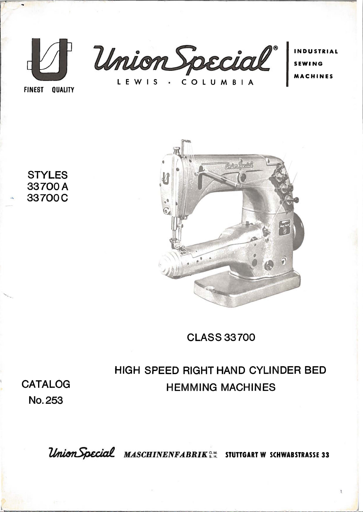
CLASS33700
HIGH SPEED RIGHT HAND CYLINDER BED
CATALOG
HEMMING MACHINES
No.253
~
MASCHINENFABRIK
~:~
:
STUTTGART W SCHWABSTRASSE
33
Page 2
CATALOG
No.253
INSTRUCTIONS
FOR
ADJUSTING
Ll
ST
OF
PARTS
AND
CLASS33700
STYLES
33700A
33700C
OPERATING
The parts listed in this catalog are furnished at list prices for repairs only.
First Edition
Printed by
~
JUSCHINENFABRIK
~:~
:
STUTTGART·W
SCHWAISTIASSE
33
October,
1965
Page 3
ADJUSTING INSTRUCTIONS
33700
33700
33700
A-16
A-16-1
C
1/2
Streamlined,
with
Two
armholes
feed
from
same.
gauge
set
Same
from
Streamlined,
with
Two
the
and
Standard
range
Speed
CAUTION:
DESCRIPTION
needle
needle,
of
dog.
3/8
at
as
3/4
needle
needle,
two
similar
Split
to
Seam
No.16.
12
S.P.I.
33700
to
operation
gauge
8
to
of
these
Operating
plain
bearing
one
bathing
3/4
specification
Needle
A-16
1
1/2
plain
bearing
one
garment.
14,
feed,
looper
folding
inch
1/2
inches
feed,
looper
covered
No.
16.
set
at
machines
direction
OF
MACHINES
right
crankshaft
machine
suits,
attachement
fold
Type
crankshaft
Seam
and
406-EFa-1
124
except
of
right
machine
seam
specification
Needle
10
S.P.I.
is
hand
and
for
with
knee
B.
attachment
fold.
hand
and
for
on
Type
4200
of
cylinder
feed
hemming
fabric
press
(inverted).Standard
Stitch
feed
the
knitted
121 GS.
R.P.M.
machines
drive
folded
that
cylinder
can
for
range
can
drive
second
406-SSh-2.
is
outerwear
machine
mechanism.
necks
next
be
adjusted
opening
8
to
be
adjusted
machine
mechanism.
part
Stitch
clockwise.
and
to
14,
of
Needle
Check
grooves.
points
the
Lubrication
As
reservoir
Arctic
of
from
always
side
must
filled
located
beginning
of
Please
oiling
lubricated.
arrow
the
200
any
of
be
the
Lever
the
vertically
oil
Oil
to
between
with
machine,
note
by
location
The
must
has
must
C
250
UNION
the
lower
added.
oil
in
the
with
that
hand
Stud
stud
point
been
be
Heavy
seconds
SPECIAL
the
The
on
base
this
below
only
twice
of
the
is
set
upward.
upward
drained
filled
or
a
at
representation.
two
red
bed.
oil
the
plate
number
the
the
a
week.
If
should
right
needJe
correctly
On
to
from
before .starting
straight
100°
lines
the
on
the
pulley.
six
lever
machines
the
the
mineral
Fahrenheit
of
level
be
renewed
side
machines
The
drain
oil
remaining
at
holes
when
with
left
machine
the
is
the
with
plug
stud
Be
below
in
the
arrow
Serial
with
oil
marked
an
before
to
operate.
oil
with
(Spec
sure
gauge
the
once a year.
top.
The
serial
screw
mechanism
relation
stamped
No.
angle
a
83),
that
on
lower
drain
numbers
is
located
with
to
D
85891
of
45°.
shipment
Use
Gargoyle
Saybolt
which
the
oil
the
right
red
The
plug
red
colour
is
automatically
its
oil
on
the
to
the
viscosity
can
be
level
front
line,
reservoir
screw
below
on
the
need
head
D
85910
obtained
is
oil
is
is
95731;
side
Cleaning
The
machine
Important:
to
operate
bearings.
to
carry
at
the
to
operate
of
Machine
must
remove
remove
Run
machine
oil
to
the
recommended
the
machine.
be
cleaned
throat
the
bearings.
speed
plate
cover
slowly
for
thoroughly
and
clean
on
the
top
for
several
Then
five
repeat
minutes.
before
feed
of
the
minutes
oiling
oiling
dog
cylinder
Close
slots.
to
and
the
the
and
allow
run
cover
six
oil
Before
oil
the
the
machine
and
starting
all
oil
begin
holes.
wicks
Page 4
Setting
Put
in
for
Style
needles
The
long
of
one
center
groove
Needles
pair
33700
in
of
C
of
needles
size
the
the
as
front
needles
Type
specified
ends
must
124 B for
and
of
the
be
directed
Style
turn
needle
the
33700
needle
slots
towards
of
A
and
bar
the
the
Type
so
throat
operator.
121
that
GS,
the
plate.
Looper
Adjust
hand
its
advantageously
When
the
can
After
move
Height
Set
inch
point
no
as
disc.
Looper
When
rear
This
the
driving
3
and 4 on
diagram
Gauge
the
needle
extreme
adjusting
looper
be
turned
again
freely
of
the
needle
below
is
lateral
this
would
Avoid
the
of
the
adjustment
looper
lever.
17998
Needle
even
Looper
looper
to
the
right
for
the
driving
until
tightening
in
its
bar
the
looper
with
motion
impair
Notion
moves
right
of
shaft
These
the
rear
M).
so
that
looper
position.
making
looper,
lever
the
complementary
Bar
so
the
of
needle
the
after
side
When
must
looper
the
that
when
left
the
looper
the
clearance
to
the
as
looper
loosening
clamp
of
inserting
the
distance
point
Looper
this
adjustment.
hexagonal
be
has
two
screws
the
top
the
looper
side
left
close
avoid
screws
the
is
3/16
gauge
screw
loosened.
the
parts.
of
of
the
drive
between
the
as
possible
motion
the
clamp
are
cylinder.
screws
from
correct
the
the
is
lever
looper
accessible
the
inch
No.
74
Then
looper
left
moving
left
occurs
take-up
can
screws
(See
3
and 4 use
center
when
21225
and
the
distance
thread
needle's
to
needle.
point
without
be
after
oiling
of
the
looper
3/16
set
screw
looper
the
left
Please
when
plate
should
contacting.
changed
in
the
removing
and
a
cement
the
can
be
96 B on
drive
to
the
take-up
eye
is
and
note
it
is
and
pass
by
looper
threading
right
is
in
used
lever
needle.
must
3/64
its
that
turned
take-up
the
turning
avoid
screws
material.
Looper
The
looper
and
barely
.002
of
Rear
Set
its
is
make
throat
the
Stitch
Regulating
at
altered
screw.
Turning
shortens
in
to.005
the
Needle
the
most
necessary
sure
needle
Range
the
left
operating
Needle
needle
touches
left
rear
forward
that
plate.
hole
the
after
it
to
it.
Guard
inch
needle.
Guard
end
remains
needle
point
after
the
Make
in
desired
of
loosening
the
To
loosen
direction.
guard
the
guard
every
entire
sure
the
the
right
is
set
front
between
so
of
travel.
change
bottom
that
presser
number
main
the
lengthens
the
lock
correctly
of
that
the
foot.
of
shaft.
nut
the
right
the
looper
it
barely
Readjustment
of
stitch
of
the
needles
stitches
The
and
turning
the
stitch,
nut
use
when
needle
length.
presser
do
per
number
wrench
it
point
contacts
of
foot
not
contact
inch
of
the
stitch
and
No.
moves
and
a
and
the
the
For
contacts
is
stitches
turning
21388
to
the
left
space
the
needle
uniform
when
accomplished
regulating
of
rear
needles
guard
entering
can
to
the
and
turn
feeding
the
be
side
at
left
it
Page 5
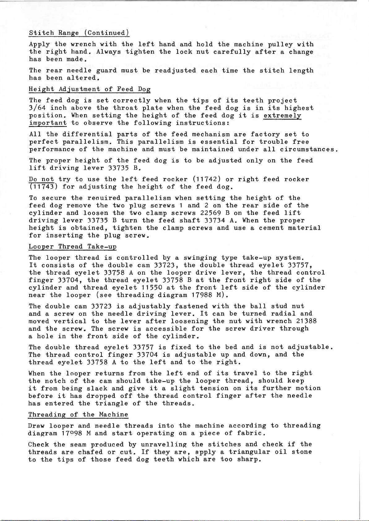
Stitch
Range
(Continued)
Apply
the
has
The
has
Height
The
3/64
position.
important
All
perfect
performance
The
lift
Do
(11743)
To
feed
cylinder
driving
height
for
the
right
been
rear
been
Adjustment
feed
inch
the
proper
driving
not
try
secure
dog
is
inserting
differential
parallelism.
for
lever
wrench
hand.
made.
needle
altered.
dog
is
above
When
to
observe
of
height
lever
to
adjusting
the
remove
and
loosen
obtained,
with
Always
guard
of
set
the
setting
the
machine
of
33735
use
the
reauired
the
33735
the
plug
the
tighten
must
Feed
correctly
throat
the
the
following
parts
This
the
feed
B.
left
the
parallelism
two
plug
the
two
B
turn
tighten
screw.
left
Dog
parallelism
height
be
readjusted
when
plate
height
of
the
and
dog
feed
screws
clamp
the
the
hand
the
when
must
rocker
of
feed
clamp
and
hold
lock
the
of
instructions:
feed
is
when
screws
nut
tips
the
the
mechanism
is
be
maintained
to
be
(11742)
the
feed
setting
1
and 2 on
shaft
screws
the
carefully
each
feed
essential
22569
time
of
feed
dog
adjusted
dog.
33734
and
machine
its
dog
are
under
or
right
the
the
B
on
A.
use
the
teeth
is
it
for
only
height
rear
the
When
after
stitch
in
is
extremely
factory
trouble
all
feed
side
feed
the
a
cement
pulley
a
change
length
project
its
highest
set
free
circumstances.
on
the
rocker
of
the
of
lift
proper
material
with
to
feed
the
Looper
The
looper
It
consists
the
thread
finger
cylinder
near
The
and
moved
and
a
The
The
thread
When
the
it
before
has
Threading
Dra~
diagram
double
a
the
hole
double
thread
notch
from
entered
the
screw
vertical
the
looper
Thread
thread
eyelet
33704,
and
looper
cam
screw.
in
the
thread
control
eyelet
looper
of
being
it
has
of
17098
Take-up
of
the
thread
on
front
33758
the
slack
dropped
the
the
and
M
is
the
33758
thread
(see
33723
the
to
the
The
eyelet
returns
cam
triangle
Machine
needle
and
controlled
double
eyelet
threading
is
needle
lever
screw
side
finger
A
to
should
and
off
threads
start
cam
33723,
A
on
the
eyelet
11550
adjustably
driving
after
is
accessible
of
the
33757
33704
the
left
from
give
the
take-up
it
the
thread
of
the
operating
by a swinging
the
looper
33758
at
diagram
fastened
lever.
loosening
cylinder.
is
fixed
is
adjustable
and
left
a
slight
threads.
into
drive
B
at
the
front
17988
for
to
to
end
the
looper
control
the
machine
on a piece
double
the
M).
with
It
can
the
the
the
the
right.
of
its
tension
finger
type
thread
lever,
front
left
the
be
nut
screw
bed
up
and
travel
thread,
on
according
of
fabric.
take-up
eyelet
the
right
side
ball
turned
with
driver
and
is
down,
should
its
after
system.
thread
side
of
the
stud
radial
wrench
not
and
to
the
further
the
to
33757,
control
of
cylinder
nut
and
21388
through
adjustable.
the
right
keep
motion
needle
threading
the
Check
threads
to
the
the
tips
are
seam
chafed
of
produced
or
those
cut.
feed
by
unravelling
If
dog
they
teeth
are,
which
the
apply
stitches
are
a
too
and
triangular
sharp.
check
oil
if
stone
the
Page 6

Thread
The
tension
produce
The
looper
the
tension
Tension
on
uniform
thread
which
the
stitches
tension
is
needle
applied
threads
on
the
should
to
should
bottom
be
approximately
each
needle
only
side
be
of
the
thread.
sufficient
fabric.
one
fourth
to
of
Needle
Set
scr
ew
wire
when
the
so
the
Thread
frame
is
in
that
loop
Take-up
needle
the
the
of
middle
thread
the
thread
of
of
right
eyelet
the
the
needle
slot.
right
in
Set
is
such
the
hand
dropped
needle
a
way
needle
from
that
contacts
thread
the
the
looper.
fastening
take-up
the
wire
Page 7
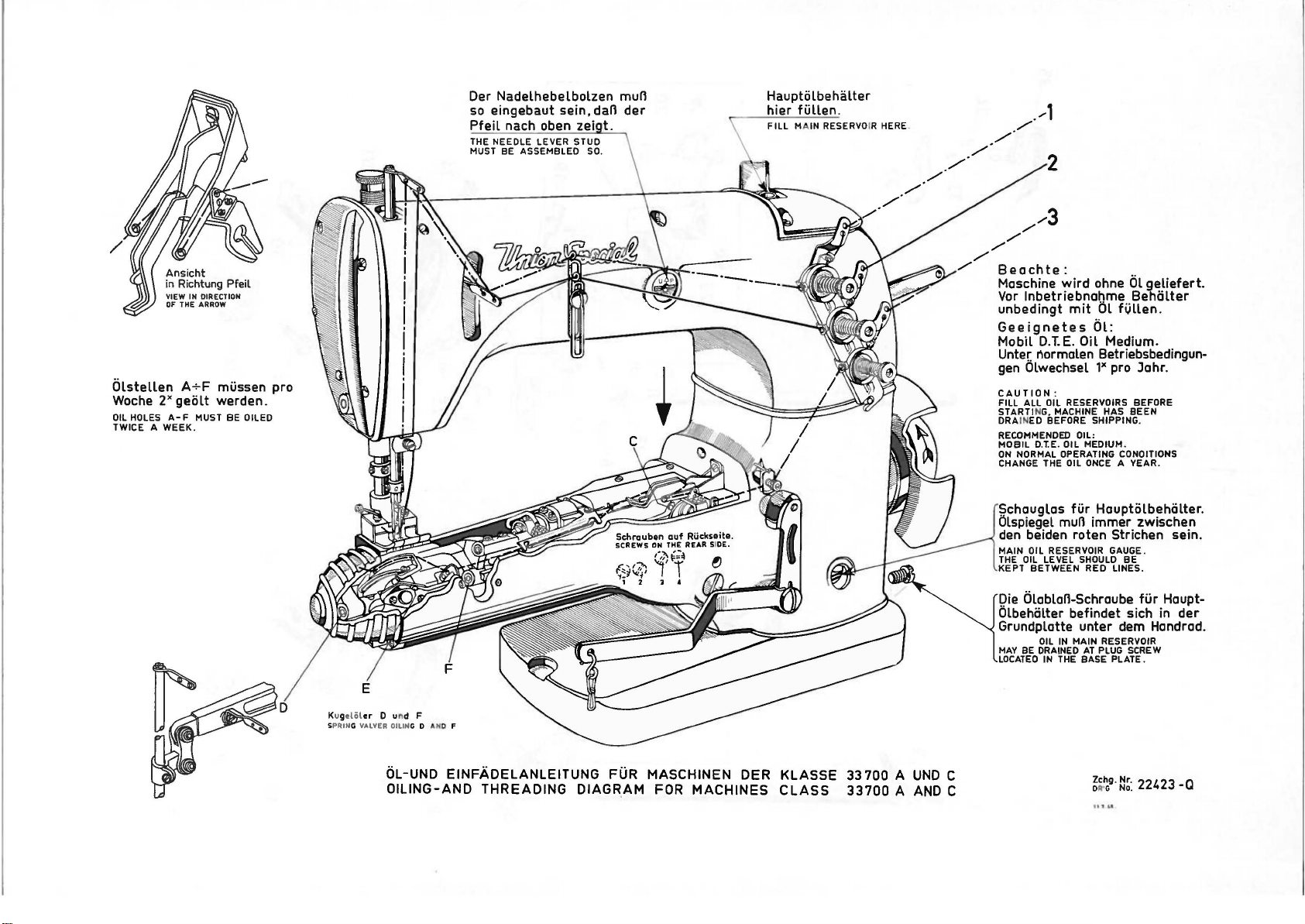
Der Nadelhebelbolzen mun
so
eingebaut sein, dan
Pfeil
nach oben
der
/...-1
_/·"'"'"
/./
/./·
Olstellen
Woche
2x
OIL
HOLES
A WEEK.
TWICE
VIEW
IN
DIRECTION
OF
THE
ARROW
A+F
geolt
A-F
MUST BE DILEO
mussen pro
werden.
Kugeliil
SPRING
er
VAlVER
0 und F
OiliN
G 0 AKO F
Beachte:
Maschine
Vor
unbedingt
wird
lnbetriebnabme
mit
Geeignetes
Mobil
D.T..
E.
Unter.
gen
Olwechsel
CAUTION:
FILL ALL
STARTI N
DRAINED
RECOMMENDED
MOBIL
ON
NORMAL OPERATING CONDITIONS
CHANGE THE
auglas
ULspiegel
Oil
normalen Betriebsbedingun-
OIL
RESERVOIRS BEFORE
G.
MACHINE HAS BEEN
BEFORE SHIPPING.
OIL:
D.T.E.
OIL MEDIUM.
OIL
fur
mun immer zwischen
..
ohne
OL
geliefert.
Beholter
OL
fVLLen.
OL:
Medium.
1x
pro Jahr.
ONCE
A YEAR.
Hauptolbeholter.
roten Strichen sein.
Die
Olablan-Schraube
Clbeholter
befindet sich in
fur
Haupt-
der
Grundplatte unter dem Handrad.
OIL
IN
MAY
BE
LOCATED
MAIN RESERVOIR
DRAINED
IN
THE
AT
PLUG
BASE PLATE.
SCREW
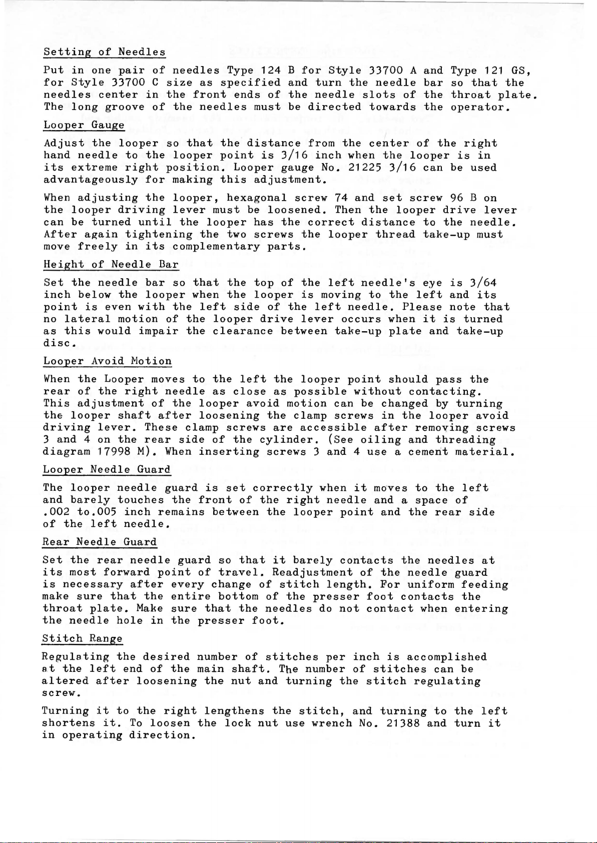
OL-UND EINFADELANLEITUNG FOR MASCHINEN DER
OILING-AND
THREADING
DIAGR.AM FOR
MACHINES
KLASSE
CLASS
33
700 A
UNO
33700 A AND
C
C
~~~9-
~~:
22423
-a
Page 8
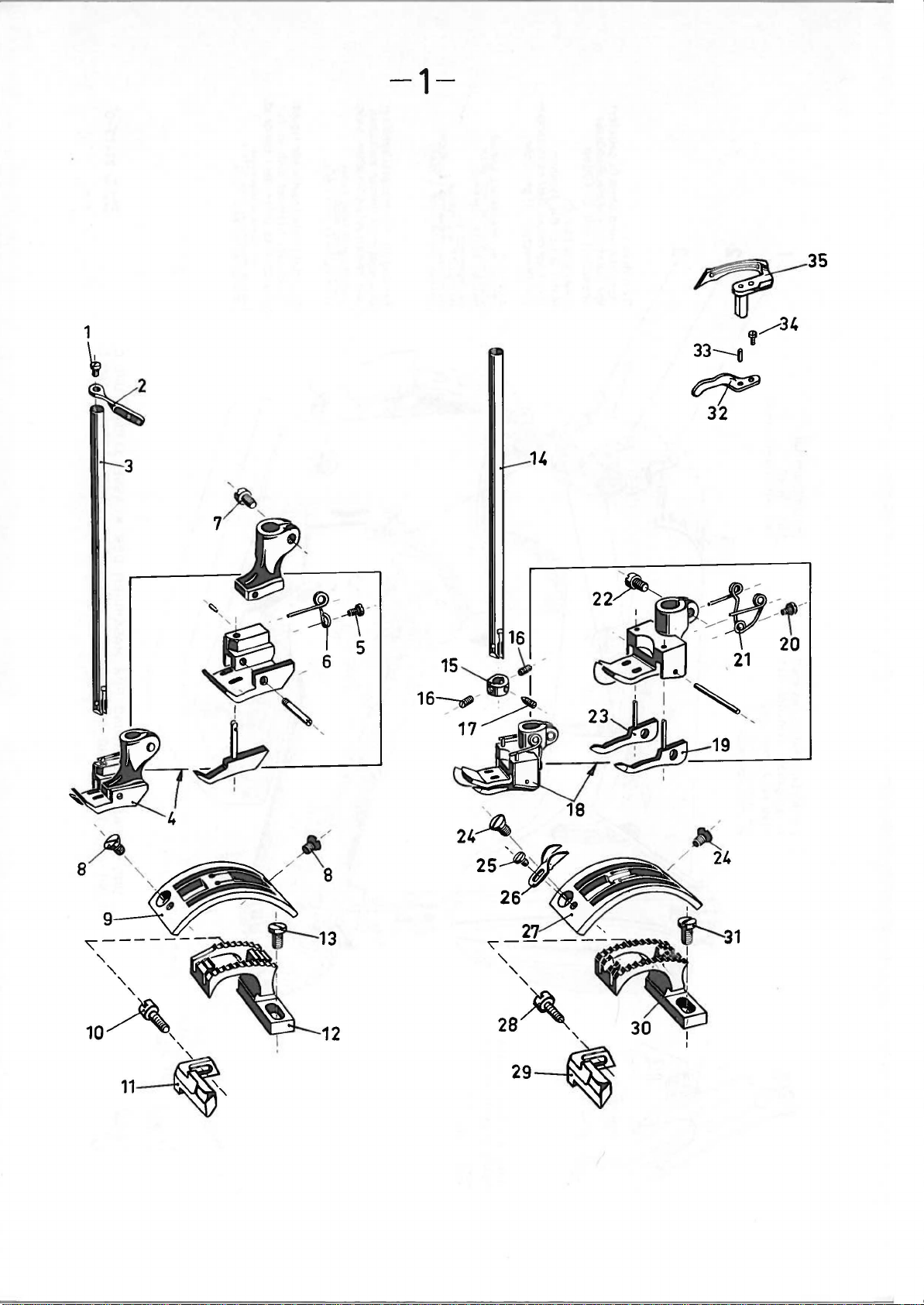
-1-
3
24
14
'
14(
/
/
24
'\------
'
~~
'
'
'
'
10~,
2
'
11~,
Page 9
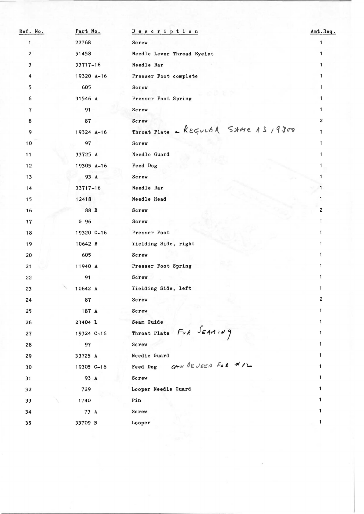
Ref.
No.
Part
No. D e s
22768
Screw
c r
t i
o n
Amt.Reg.
i
E
10
11
12
13
14
15
16
17
2
3
4
5
6
7
8
9
51458
33717-16
19320
31546
19324
33725
19305
33717-16
12418
G
605
91
87
97
93
88
96
A-16
A
A-16
A
A-16
A
B
Needle
Needle
Presser
Screw
Presser
Screw
Screw
Throat
Screw
Needle
Feed
Screw
Needle
Needle
Screw
Screw
Dog
Lever
Bar
Foot
Foot
Plate
Guard
Bar
Head
Thread
complete
Spring
....
Eyelet
R
c~vL~
S;tJ~te.
A._
It S 1
'i
Jcro
2
2
18
19
20
21
22
23
24
25
26
27
28
29
30
31
32
33
19320
10642
605
11940
91
10642
87
187
23404
19324
97
33725
19305
93
729
1740
C-16
B
A
A
A
L
C-16
A
C-16
A
Presser
Yielding
Screw
Presser
Screw
Yielding
Screw
Screw
Seam
Guide
Throat
Screw
Needle
Feed
Dog
Screw
Looper
Pin
Foot
Side,
Foot
Side,
Plate
Guard
Needle
right
Spring
left
FIJ~
dt
Ck
N
Guard
f€/fM
J~f£t)
u / J
~
"
~
2
-*1\...
34 73
35
33709
A
B
Screw
Looper
Page 10

-2-
Page 11

Ref.
No.
Part
No.
D e s c r i p t i o n
Amt.Req.
2
3
4
6
7
10
11
1 2
13
14
1 5
1 6
17
18
19
20
21
22
23
24
25
26
27
28
29
30
31
12
33
34
35
36
37
38
39
40
41
42
43
44
45
46
47
48
49
22768
51458 A
J 87 J
33759
57
57
57
WB
we
WD
A
5
8
9
51458
22768
22889
539
20
22848
22849
A
33704
33757
22766
33723
22849
33658
A
A
33758
33758
c
22768
33758
33758
73
A
A
B
77 p
33792
G
50-153
G
1346
D
51959 B
51959
c
51959 D
33760
c
23388 L
90968
51292 c
51292
51292
F-2
F-8
109
51292 G
51292 A
51292 D
51491
c
43266
668-25
668-28
52892
21657-3
Screw
Needle
Bar
Screw
Nipper
Nipper
Nipper
Spring
Spring
Tension
Shoulder
Needle
Lever
Screw
Adapter
Frame
Needle
Washer
Screw
Screw
Looper
Looper
Thread
Thread
Screw
Looper
Thread
Screw
Looper
Thread
Thread
Channel
Cylinder
Screw
Looper
Thread
Screw
Looper
Thread
Screw
Spacing
Pin
Thread
Thread
Thread
Thread
Lifter
Nipper
Nipper
Nipper
Nipper
for
Torsion
Screw
(Class
Tension
Tension
Tens1on
Tension
Tension
Tension
Tension
Lead -in
Nut
Eyelet
Locking
Tension
Tension
Thread
Screw
Screw
Looper
Stud
Hemming
Spring
Nut
Spring
Spring
Disc
Post
Post
Thread
Thread
Ring
Post
Disc
Eyelet
Base
Plate
Spring
Thread
Thread
Pull-off
Guide
Take-up
Guide
Guide
Thread
Guide
Guide
Tension
Disc
Spring
Nut
Attachement
(Class
33700
A)
(Looper)
(Needle)
Ferrule
Eyelet
Guide
Support
Separator
Eyelet
Eyelet
Eyelet
Post
33700
A)
(Class
33700
2
2
2
2
A)
3
2
6
3
3
3
3
1
6
6
Page 12

~
-~-
/~
/ _ _ _
-
-------
Houp
tw.
Bu
MAIN SHAFT BUSHI
---"I
__
)!
53
-
(1")
ch~
e
lin
ks.
NG,
LEFT
F1
tl
I
v
52
1L.
15
16
17
J
">
">
I
I
w
n
--r::·., ..
-+-
---
2o
I
11
.: ' •
I
=
~~
(~~ablaOschraubo)
ORA
IN
PLUG
SCREW
25
(
5.)
26
~~
-
,
Page 13

Ref.
10
11
12
13
14
15
16
17
18
1 9
20
21
22
23
24
25
26
27
28
29
30
31
32
33
34
35
36
37
39
40
41
42
43
44
45
46
47
48
49
50
51
52
53
54
55
56
Part
51256
51254
22586
51250
51250
660-212
51250
51150
719
719
90
33782
660-207
666-170
52883
660-212
21657
99274
22569
33791
33790
41394
999-4
22733
90939
33742
22580
22539
666-121
22580
15430
999-2
999-19
999-1
50-506
15430
w
97
22539
33790
33794
HA
73
33742
33742
33794
33794
33790
73
96300
33794
22562
22585
80699
51254
33755
80273
No.
N
c
R
F
D
A
AE
R
X
B
A
A
B
II
c
L
L
c
c
c
B
E
c
A
B
c
B
A
D
A
D e s c r i p t i o n
Presser
Needle
Screw
Gasket
Washer
Oil
Bushing
Needle
Screw
Screw
Screw
Needle
Oil
Felt
Foot
Oil
Tension
Screw
Screw
Crankshaft
Bushing
Gasket
Felt
Plug
Screw
Looper
Screw
Plug
Oil
Screw
Felt
Gasket
Felt
Retaining
Oil
Felt
Wick-Yarn
Plug
Main
Oil
Screw
Bushing,rear
Bushing,front
Oil
Oil
Crankshaft
Screw
Split
Oil
Screw
Screw
Dowel
Needle
Presser
Presser
Spring
Bar
Seal
Ring
Lever
Lever
Seal
Ring
Wick
Lifter
Seal
Ring
Release
Oil
Wick
Screw
Drive
Screw
Wick
Wick
Ring
Set
Wick
Screw
Shaft
Tube
Tube
Channel
Pin
Tube
Pin
Bar
Bar
Foot
Bushing
Shaft
Bearing
Lever
Bearing
Lever
Ring
llushing
Bushing
Bushing
Bushing
Guide
Regulating
Stop
Bushing
Lever
Housing
Shaft
left
middle
Lower
Bar
Oiler
Shaft
Lower
Bushing
Stud
Collar
Amt.Req.
1
Bushing
4
3
2
5
2
No.
2
3
4
5
6
7
8
9
G
G
Page 14

~
~
---
11
12
(C
omp
l.l
1
3
\
{~)
~--
~
£·
~~
~~~
-:_---
13
14
5
15
.t---
1
43
~~
32
~~
i2
(h)
OJ)
G)rffij
18
19
Page 15

No.
Ref
.
2
3
4
5
6
7
8
9
10
12 52882
13
14
1 5
16
17
18
19
20
21
22
23 22849
24
25 22766
26 525
27 523
28 524
29
30
31
32 33785
33
34
35
36
37
38
39
40
41
42
43
44 61321
45
Part
No. D e s c r i
33782
22569
33782
33782
A
AE
90
52882
AA
50-789
52882
39582
22541
AC
L
B
AD
90
52882
33782
33782
51190
G
33782
99273
33757
33782
33782
33785
p
y
B
D
50-434
K
A
A
G
F
c
22564
33785
A
B
G
353
357
97
352
96851
660-202
311
21
A
31175
22894
B
G
22581
61321
J
L
22574
Head
Cover
Screw
Gasket
Needle
Lever
Screw
Oil
Drip
Pin
Spring
Oil
Cap
Screw
Crank
Chamber
Screw
Gasket
Baffle
Plate
Gasket
Gasket
Oil
Sight
Gasket
Screw
Gasket
Gasket
Screw
Oil
Reservoir
Screw
Cylinder
Cylinder
Spring
Cylinder
Screw
Spring
Cylinder
Hinge
Spring
Screw
Screw
End
Cap
Pin
Oil
Ring
Pulley
Belt
Guard
Screw
Screw
Handwheel
Washer
Screw
Plate
Gauge
Cover
Cover
Cover
End
Hinge
t
i
E
Bearing
Cover
Cover
Bolt
Bolt
Cap
o n
Plate
Knob
Amt.Req.
5
Oiler
2
1
3
2
4
1
1
5
2
2
3
Page 16

-5-
N
c.o
~~~e~
Page 17

Ref.
2
3
4
5
6
7
8
9
10
11
1 2
13
14
1 5
16
17
18
19
20
21
22
23
24
25
26
27
28
29
30
31
32
33
34
35
36
37
38
39
40
41
42
43
44
No.
Part
33783 H
660-207
402
22596
21657
318
33783
33783
33783
21657
21657
51216
51
216
29066
51216 p
51216
22559
33716
G
29348
33715
51250
22768
51458
666-149
51054
51254
22562
33755
51257
33783
G
52888
22562
53783
22758
53783
33783
G
22557
51256
33783
77
54
78
88
402
No.
y
N
T
u
X
w
K
L
R
N
G
G
c
D
F.
H
A
K
B
A
c
L
s
B
c
M
D e s c r i
Seal
Stud
Pin
Foot
Ring
Lever
Lever
Spring
Release
Release
Lever
Lever
Lever
Lever
Lever
Lever
Lever
Lever
Bar
Foot
Bar
Bar
Bar
Lever
Lever
Lever
Spring
Lever
Presser
Oil
Screw
Screw
Connection
Screw
Lifter
Lifter
Return
Tension
Tension
Needle
Ball
Needle
Nut
Washer
Screw
Needle
Needle
Needle
Needle
Screw
Screw
Needle
LUbricating
Link
Needle
Screw
Needle
Screw
Presser
Presser
Presser
Screw
Shoulder
Presser
Screw
Lifter
Screw
Lifter
Lifter
Shoulder
Presser
Lifter
l! t i o n
Lifter
Link
internal
Return
Holder
Conn.Rod
Connecting
Connecting
Asserr.bly
Stud
Thread
Felt
Link
Connection
Guide
Connection
Screw
Stop
Link
Bell
Bell
Screw
Connecting
Lever
Lever
Bar
Collar
Crank
Crank
Lever
Spring
Shaft
Shaft
Bearing
Eyelet
Rod
Rod
Spring
Rod
Bushing
upper
Ball
Joint
Assembly
Amt.Rcq.
upper
2
2
2
2
2
2
1
1
Page 18

Oil-Wick
Oldocht.
----------..
96
----------------
95
------
94----~
+~'b
(Compl.)
Oil-Wick
o~f~
~~~©
88~
'-.,-'
87
!Compl.J
j
-:::::::::----\
\
78
r;
6
f
1
(Compl.
l
'
~
~
0
,
e _
.
---.---
\
r f (
i i ! " • i
71
__...-
(eom,u
fir"
...--
. . .,. I ,
.
70
---
----·-----·
~
18
~
Ill
jJ
, I
!Compl.l
7
-~
[f"
'
~
I,,, t
d
~I
~~~~.
~~¥,
L
23
~
.
DiJ~!
--
29
l L
•
r,
l:
~~J-~fiiiiiii';;r...;
J__.--y
32
··-
55
(Compl.l
~~
1'i-~;;r-~~~~~e~-->------~;.;-
~~:;;;;;;~;;:;;;.~~~65
tJ'
'';,1
lf
1
73
n I ' $
_k~
w-ss I
-~"
sa-&'--"
---·
------------------
' . " I\
·
__J
------
53~
51
~49
1
('
)'5
/
{.®~~
@_
·
~
i
,,.
~
~
\\' \\
__
48
/
~-38
""'
®----39
40
\,;
47
1.6
\
'
~43
'~
~43
en
I
Page 19

Ref,
10
14
15
33
34
35
36
37
38
40
41
42
43
44
45
46
47
48
49
50
51
52
53
56
57
59
60
61
62
63
64
65
66
67
68
69
70
71
72
73
74
75
76
77
78
79
80
81
82
83
84
85
86
87
88
89
90
91
92
93
94
95
96
11
12
13
16
17
18
19
20
21
22
23
24
25
26
27
28
29
30
31
32
39
54
55
58
No.
1
2
3
4
5
6
7
8
9
Part
No,
G 29476 H
33706
33735 c
22894 D
p
1-18
666-82
G 29476
33714 A
33745
22894 D
22894 D
666-82
p
1-18
51236 A
666-149
51236 A
666-149
33735 B
22569 B
HA
73
33744 B
HA
73
22569 B
G 29476
GA
B
B
T
33722 E
51216 M
J
51216
G 22559 C
33743
33743 B
97
A
33766
22894
X
33743 A
80175
33742 G
39243 H
51242 M
18
89
99280
33742 H
22580
33742 A
96
B
22829 A
12538
E
21657
74 A
33737 A
33736
33739 A
22562
A
36
G 29163 A
33733
1096
11513
22565
88
c
33744
12982
77
A
33744
J 80 K
82
304
77A
17
33722
33745 A
33745 B
999-50
33745
A-1
61434 G
18
305 A
11743
98
88
33734
A
33734
22706 A
11742
98
22580
33734 B
80090 E
c
12964
HA
1286 B
33734
B-1
33734 c
80090
E
12964
1286 B
33734
c
C-1
HA
D e s c r i p t i o n
Feed
Drive
Drive
Wick
Avoid
Avoid
Eccentric
Connecting
Eccentric
Sleeve
Connecting
Eccentric
Feed
Screw
Pin
Felt
Looper
Eccentric
Looper
Screw
Screw
Pelt
Wick
Pin
Link
Pin
Oil
Wick
Link
Pin
Oil
Wick
Feed
Drive
Lever
Screw
Screw
Looper
Avoid
Drive
Lever
Screw
Screw
Crankshaft
Crankshaft
Needle
Connecting
Screw
Looper
Ball
Bearing
Lever
Stud
and
Rod
Bearing
Needle
Roller
Bearing,
Screw
Stop
Collar
Screw
Guide
Pork
Screw
Looper
Locking
Washer
Nut
Screw
Screw
Looper
Screw
Looper
Drive
Stud
Drive
Drive
Lever
Lever
Lever
Shaft
intermediate
Screw
Screw
Nut
Washer
Screw
Looper
Ball
Ball
Screw
Ball
Looper
Looper
Adjusting
Looper
Screw
Screw
Locking
Lever
Washer
Stud,
Stud,
Rocker
Rocker
Rocker
Washer
Connecting
right
left
Assembly
Cone
Screw
Nut
Screw
Looper
Locking
Stitch
Feed
Screw
Peed
Main
Peed
Bushing
Needle
Feed
Washer
Nut
Eccentric
Peed
Screw
Screw
Peed
Peed
Screw
Peed
Shaft
Screw
Regulating
Crank
Crank
Shaft
Crank
Bearing
Drive
Stud
Rocker,
Bar
Rocker
Rocker,
Stud
Stud
Link
Link
right
Shaft
left
Screw
Cap
Assembly
Screw
Screw
Feed
Bar
Plug
Ball
Spring
Feed
Peed
Plug
Screw
Bar
Bar
Screw
Driving
Driving
Driving
Stud,
Stud
Stud,
Ball
Spring
Feed
Bar
Driving
Stud
and
Link
Link
and
Link
Bearing
lower
Rod,
right
left
Assembly
Link
Assembly
compl.
Assembly
Amt.Req.
1
1
1
1
1
1
1
1
1
2
2
1
1
1
1
1
1
1
2
1
1
1
2
1
1
28
1
2
1
1
2
1
2
1
1
1
1
1
1
1
2
1
2
1
1
1
1
1
1
1
1
1
4
1
1
1
1
1
1
2
1
1
1
1
1
1
1
2
1
1
1
1
1
1
1
1
1
1
4
2
1
1
1
1
1
2
1
1
1
1
1
1
1
1
1
1
Page 20

-7-
Page 21

Ref.
No.
Part
No. D e s c r i
:2
t i o n
Amt.Reg.
2
3
4
5
6
7
8
9
10
11
12
13
14
15
23389
23)88
90
23389
187
22524
23388
23388
605
23388
23389
531
12934
22514
240
23388
Attachment,
c Hemmer
Screw
B
A
D
E
F
A Hemmer
A Nut
J
Hemmer
Screw
Screw
Hemmer
Hemmer
Screw
Hemmer
Screw
Screw
Link
Folder
Scroll,
Tongue,
Sliding
Edge
Scroll
Base
Stud
Rod
complete
adjustable
adjustable
Block
Guide
Rod
(Ref.No.1-12)
2
2
2
2
2
2
16
17
23388
25
K
cc
Folder
Screw
Rod
Extension
2
Page 22

-8-
AUSROCKHEBEL
LIFTER
FOR KNEE PRESS-OPERATION
FOR
-----
- ·
-·
-·
-·
FOR
APPARAT
SPLIT TUBE HEMMING ATTACHEMENT
__
.-4.~
~
/ '
_
...
/ - -
~
.'\
------
/ .---
./
~
--.::.
.-.----.---
23389
~~-
L 1
I
""~~--~~
I
FOR
FOR
-r-
~
KNIEHEBELBETATIGUNG
CLASS
-
i 1
~-
-~
I I
..
/
·:-.,
,,
_ _u
23389
33700
A
2
-·~
---
·
3
21691
Kniehebel kompl.
Knee
Lever
compl.
I i
I i
J...i-
h
-1
12
7
9
Zchg.
18
.8.
65
Nr.
22413-0
Page 23

Ref.
No.
Part
No.
D e s c r i p t i
o n
Amt.Req.
2
3
4
10
11
12
1 3
Lever
21691
33760
c
421
D-10
21679
28505
5
6
7
8
9
660-128
98
9271
69
21665
21677
21664
21661
21662
FD
Knee
Folder
Knee
Chain
Chain
Chain
Screw
Collar
Set
Chain
Plate
Knee
Knee
h.nee
Press
Screw
Operating
Rod
Spring
Rod
Rod
Spring
Rod
Rod
Press
Press
Press
compl.
Chain
and
Plate
Plate
Jracket
Bracket
Lever
Screw
Connection
Shaft
Eye
2
2
5
2
Page 24

~
---
--
-
-9-
E'
m
M
N
N
.ci
:Zz
•
01
UIC
01
"-
.c.~
uo
NL.
0
z
0
I
a..
(J)
U")
.....
z
0
I
a..
(J)
--'
:o
Page 25

Ref.
No.
Part
No.
D e s c r i p t i o n
Amt.Reg.
53394
2 53394
3
G
4
5
6
7
8
9
1 0
11
1 2
13
14
15
50-520
G
50-521
666-209
666-201
21212
51294
31194
43443
31194
666-214
31194
75
87
p
R
N
Q
u
A
B
Oil
Siphon
Oil
Siphon
Screw
Oil
Tube
Siphon
Siphon
Felt
Oil
Siphon
Oil
Tube
Oil
Siphon
Nut
Screw
Oil
Tube Clamp
Felt
Felt
Cup
Plug
Connection
Lint
Assembly
Clamp
Disc,
Connection
Tube
Filter
felt
Locki
ng
Page 26

-10-
~
30
Page 27

Ref.
No.
Part
No.
D e s c r i p t i o n
Amt.Req.
10
11
1 2
13
14
1 5
16
H-4
21101
2
3
4
5
6
7
8
9
21114
21114 M
21114 L
21114
21114 w
21104 v
21114
S-4
258
A
652-16
H-4
21114 L
21114
M
22651 CD-4
21104
B-24
21114
D-4
22651 CD-5
Thread
Thread
Eyelet
Eyelet
Nut
Washer
Spool
Spool
Pad,
Thread
Eyelet
Eyelet
Screw
Thread
Thread
Screw
Stand,
Stand
Locking
Seat
Pin
for
Stand
Locking
Stand
Stand
Disc
thread
Eyelet
Rod
complete
Lead
Eyelet
Ring
Ring
Seat
4
4
8
4
4
4
4
Support
8
8
2
2
17
18
19
20
21
22
23
24
25
26
27
28
29
30
21104 H
652-16
21114 u
21114 T
22651
CD-4
22810
21114 A
22651 CD-3
21201
660-240
21388
21388
421
AE
D-38
21388 w
Nut
Washer
Split
Lead
Socket
Eyelet
Screw
Screw
Thread
Stand
Screw
Screw
over-all
Driver,
7
Tweezers
Wrench,single
Wrench
Treadle
Wrench,
9/32
Chain
curved
Socket
Base
9/64
5/8
end,
inch
Ball
inch
inches
3/8
socket
double
round
inch
with
end,
blade
opening
extension
9/32
inch
2
2
2
length
opening
Page 28

Part
No.
17
•....•..•••
18
..•••.•••••
PI
18
••...•..•••
20
•••.•.•.•.•
25
cc
36 A
....•..••
G
50-153
G
50-434
G
50-506
50-520
G
G 50-521
50-789
54
•.........•
57
WB
57
we
57
WD
69
FD
73 A
•••••••••
HA
73 B
•.......•
73 c
.........
74
A
•••••••••
75
•.•••••...•
77
••••••...••
77
A
•••••••••
77 P •••••••••
78
...•.•....•
J 80 K
J 87 K
G 96
w
82
87
87 u
88
88
89
90
91
93A
96 B
97
97
98
109
•••••••••
•...•.....•
•....•...•.
.........
•••••••••
•••••..••••
B
•••••••••
........•..
••..•.••..•
.••••••.•••
..••.••••
•••••••••
•••••.•••.•
••••.....••
•.••••••.••
••.•.•.••••
•..••••••••
187 A •••••....
240
•••••.•••••
258 A •.•••••••
304
•.•.•••••.•
305 A
..•••••.•
•••••...•.•
318
•...•..••.•
352
G 353
•••••.•...•
........
•...•.•
•......
••...••
.....••
......•
•...•.•
••••••••
••••••••
••••••••
••••••••
6
6
6
2
7
6
2
4
3
9
9
4
5
2
2
2
8
1,2
3,6
3
6
9
5
6
2
5
6
6
1
9
2
5
,6
1
6
3,4
1
1,6
6
1
1,4
3
6,8
2
1,7
7
1 0
6
6
5
4
4
'7
Part
No.
357
•••.••.••••
402
..•.••....•
G 402
•••..•...••
D-1
421
421
D-38
523
••.•......•
•.•......••
524
525
•...•.....•
531
•..•......•
539
...........
605
..•....•.•.
652-16
........
660-128
660-202
660-207
660-212
660-240
666-82
•...••••
666-121.
666-149
666-170
666-201
666-209
666-214
668-25
668-28
719
729
999-1
999-2
999-4
999-19
999-50
1096
HA
1286
G
1346 D ••..•••••
1740
9271
•.••..••
...••.••
.•...•••...
•..•..•••..
.•...•.•.
.•...••••
••......•
....•.••
.•..•.••
.....•.••.•
B
•........
•..••.•••••
••••••..•••
10642 A •.••••..•
10642
11513
11742
11743
B
•••••••••
•••.•••••••
•..••••••••
••.•.••••••
11940 A •••.•••••
12418
.•.••••••••
••.•••.••••
1 2538
12934 A •..••••••
12964 c .•.••••••
12982
••..•...•••
15430
15430
G
1
........•
1
........•
0
••••••
.•.•••
...••..
•..•.•.
•..•••.
.••••••
..•••••
......
•••.•••
•....••
•••.•••
•.••.••
.••••••
NUMERICAL
4
5
5
8
1 0
4
4
4
7
2
1
'7
10
8
4
3,5
3
10
6
3
5,6
3
9
9
9
2
2
3
1
3
3
3
3
3
6
6
2,3
1
8
1
1
6
6
6
1
1
6
7
6
6
3
3
INDEX
OF
Part
19305
19305
19320
19320
19324
19324
PARTS.
No.
A-16
C-16
A-16
C-16
A-16
C-16
21101 H-4
21104
21104 H ..•..•..
211
04
v
21114
..••.....•
21114 A
21114 D-4
21114 H-4
21114 1
21114 M
21114
21114 T ........
21114 u
21114
21
21212
21388
201
w
•.••..••••
•.•••..•••
•...••.•.•
21388 w
21388
AE
21657-3
21657-E
21657
2t657
w
x
21657 y
.•....•.••
21661
•••••...••
21662
21664
•..•...•••
21665
..•••....•
21677
•••.•..•.•
21679
•..•.....•
21691
••.••.•.••
22514
•..••..•••
22524
•••.••.•.•
22539
22541
22557 B ••.•••••
G
c
B
22559 G
G
22559 C ........
22562
••••••••••
22562 A
22564
•••••.••••
22565
•••••.•.••
22569
•.••••.•••
22569 B ••...•••
22574
••.•••••••
••••.
.••..
••..•
.....
.....
....•
..•..•
B-24
....•
........
..••....
......
•.....
........
••••••••
S-4
•....•
........
........
........
.......
..••..•.
.......•
........
........
••••••••
........
........
........
........
1
1
1
1
1
1
10
10
10
1 0
10
10
10
10
10
1 0
10
10
10
1o
1 0
9
10
to
to
2
6
5
3,5
5
8
8
8
8
8
8
8
7
7
3
4
5
5
6
3,5,6
5
4
6
4
3,6
4
Part
No,
22580
..........
22581
...•.•..••
22585
..........
22586 R .......•
22596
..........
22651
CD-3
CD-4
22651
22651
CD-5
22706
A
B
22733
22758
c
22766
..........
22768
..........
22810
..........
22829 A .......•
22848
•........•
22849
........••
22849 A ......••
22889 A
22894 D
22894 G
x
22894
23388
c
23388 D
23388
E
23388
F
23388
J
........
23388
23388
23389
K
........
1
........
..•.......
23389 A •.......
23389
23404 L
28505
G 29163 A
G 29348
G 29476
G
29476 H ....•...
G
29476 T ...•....
31121 A
31175 B
31194
B
••.......•
29066 R
c
GA
•...•.....
••••••••
........
........
•...•..•
........
........
•••....•
31194 A ..•..••.
31194 B .•....•.
31546 A ..••...•
33658 A •.•.•.••
33704
•..••....•
3~706
.••...••••
33709 B ........
33714 A ••.••..•
•....
.....
.....
••••••••
........
........
•......•
•.....••
•......•
.......•
........
•......•
........
••••••••
......•
3,6
4
3
3
5
1 0
1 0
1 0
6
3
5
2,4
1
10
6
2
4
2
2
6
4
6
7
7
7
7
7
7
2
7
7
7
1
8
5
6
5
6
6
6
4
4
9
9
9
1
2
2
6
1
6
,2
,5
Page 29

Part
No.
Part
No.
NUMERICAL
INDEX
Part
OF
PARTS.
No.
Part
No.
33715 D
33716 G
33717-16
33722
..........
33722 E
33723
...••.•..•
33725 A
••...•••••
33733
••.•.•.•••
33734
33734 A
33734 B
33734
33734
33734
33735 B
33735
33736
33737 A
33739 A
33742 A
33742
33742 E
33742 G
33742 H
33743
33743 A
33743 B
33744
33744 B
33744
33745
33745 A
33745
33745 B
33755
33755 A
B-1
c
C-1
c
••..••...•
c
..••.....•
••.••.••••
c
•..•••••.•
A-1
•..•••••••
...•..••
.......•
••.•..•
••••...•
.••.•.••
...•...•
.•••.•.•
••...•
.......•
•.•..•
...•...•
........
•••.•..•
•.....••
•....•.•
........
..•....•
....•..•
...•...•
...•...•
••••••.•
•.•.••••
........
•••.••••
••••.•
•.•.••••
••.•.•.•
5
5
1
6
6
2
1
6
6
6
6
6
6
6
6
6
6
6
6
6
3
3
6
3,6
6
6
6
6
6
6
6
6
6
6
5
3
••.•••.••.
33757
33757 A
33758
•...••.•••
33758 A
33758 B
33758
33759
33760 c
33766
33782
33782 A
33782 B
33782 F
33782 G
33782 K
33782
33782
33783
33783 H
33783 M
33783 N
33783 8
33783
33783
33785
33785
33785
33790 A
33790 B
33790 c
33791
33792
33794
33794 A
33794 B
33794
c
•.••.••.••
••••••..••
••••••••••
Y
AE
.•.•....•.
T
u
A
B
c
•.•..•••••
••••••••••
••.•••••••
c
•.•....•
..•..•••
.•.•.•.•
.......•
........
.••.••••
•••..•••
•.•.•.••
•••.••••
.....•••
•.....•.
.....••
......••
•......•
..•...••
.......•
•......•
........
•......•
•..••.••
........
..•...••
.••.••••
........
.••.•.••
•..•....
........
2
4
2
2
2
2
2
2,8
6
4
4
4
4
4
4
4
3,4
5
5
5
5
5
5
5
4
4
4
3
3
3
3
2
3
3
3
3
39243 H
39582
41394 A
43266
..•.....••
43443
51054
••••••..••
51150
•.•...••••
51190
51216
51216 K
51216 L
51216
51216
51216
51236 A
51242
51250 A
51250 D
51250 E
51250 F
51254
51254 D
51254 H
51256
51256 N
51257 K
51292 A
51292
c
51292 D
F-2
51292
51292
F-8
51292 G
51294 N
51458
•.•....•.•
51458 A
51491
c
•..•.•••
1
.......•
•....•••
Q
•.••..••
D
••.•..••
J
.......•
•..•••••
•..•.•••
•••.••••
M
.•..•..•
N
p
••••••••
•.•.•..•
•.....••
M
••.•....
...•.•••
..•.•.••
•.....••
c
........
........
........
c
........
•.....••
.•.....•
.......•
........
•.•...••
•..•••
.•..••
..•••..•
•.•.••.•
•.•.....
........
6
4
3
2
9
5
3
4
6
5
5
6
5
5
6
6
3
3
5
3
3
3
5
5
3
5
2
2
2
2
2
2
9
1
2
2
,2,5
51959 B
51959
51
959 D
52882
52882
52882
52882
52883 R
52888 B
52892
••.••..•••
53394
53394 R
53783 A
53783
61321
61321 L
61434 G
80090 E
80175
••......••
80273
.•....•...
80699 A
90939
••.......•
90968
.........•
96300
.........•
96851
••........
99273 A
99274
..••.....•
99280
.........•
.......•
c
........
......••
AA
•..••.•
AD
••.•..•
AC
••....•
P
••.•.•••
.•.••..•
••••..••
P
•••..•••
.......•
•.......
1
........
J
•......•
•.......
...•.•.•
•....•.•
••......
.......•
2
2
2
4
4
4
4
3
5
2
9
9
5
5
4
4
6
6
6
3
3
3
2
3
4
4
3
6
 Loading...