

Page 1
INDUSTRIAL
SEWING
f-'-,
I'r-
FINEST
QUALITY
elektrische:
POWER
LEWIS
PRUFANLEITUNG
PACK,CIRCUIT
COLUMBIA
DESCRIPTION
UBER
ABOUT
KLIPPAB-MASCHINEN
KEIPP-IT-MACHINES
MACHINES
•h-
/
Yi:
'•X-
•. ,
^hrj.V.
;.. ..i
Ik'
Vi,;
j
r.''7.
^
( 1 J ;i; •
•'•
KATALOG
CATALOG
;
>'•
. ,
.,
• • . " ! , •A.* I * • ^
232
":x
.%
' 'i'. r " ^ •' \ • y '" 'l>• '
.•••'
':'M
ii'>
fjX
i'.
V/.
•'4
oXiyAjii
NR.
NO.
B
:,••
* , .
•••
CLASSES
33500
33600
33700
•
- xrt -
fvv-'^-.r*sv
n«..ve«ifiAr^
'fti
X
:k'--
,
••','•
5'.
V'.vt
V-
• •^-- .
v.-
'.V
••••V-^'-/
/«
VS~
, ' \
- •'H
''-f
4 u
r*
.''•
•-
i^'' • /" !
VmlmSpeJCial.
'•.i'
- ' V/ ;-. •. •! :., '
••'••--
..>•/.• , ' • h-
MASCHINENFABRIKtl
STUTTGART
) A
'1,5
,,
iAxAA/xAVA'ti.'y;
XAA
VlsvfeA'"',
t A
W
SCHWABSTRASSt
33
t .
>,^•6-.
•. ' k •*„ ft
'•%
.''Lr
Page 2

I..\.
.'i'
'
.!,•
•
V ' ;'
'T
I
'l'-
'•
- '
. . • c
r
•'
7'/
. • '. " •.--
;:iV
^-
r '
^•V
\ ••
X'
'1 •:
"
• 1"
•'
, -• •, V
. 1.
1 ,'
;•
s ^'
•r"
; • •-
••
••^'
: ^
V
/
'-' V
r
.
•'
<- •
••
.'X
.1
- •-, ' ,V, - •• y
•"Xi'x^
.•>^•'r
.v-VX'
• • -.y
• '. '
.-
x:xx
,^
:,'r.
, -v,, ^
•!:'v
^
-^.
x-
';.
V
.•;•:••
./VA'
/x-:";
^ .V-.
••
'
',, • .
•-.>
,, f. •
•'
---
.-•.V.. '• ^
•( .1 •
'"••V•-•"r:
'•
• -•.
;•.'
-•.
" ^ "/ i , ^ •
-
•'
?v:
',/
>«>
• ..' '
•i
•
,7
-.1^ ^ •
•,
x''
• 7
\ -
*7'.
• • • • • . -' •' , - ^ t- ' ''• /-- s•»•
.X'
• -''s .
.I'
v • x-
yr
,x
••.-^
x • ,;•,
x.,o-.^x
7 7 -
-';•/-
7'
'
I /, ,
•'•i
',7'
-.-•
, ;• •
^'-
'-^rn
,•
- '.i.;'
/^£-
7x',f
.
..€'
7.,
;\7'7
,'•>7.
>^-'
-J,.'
x^rxX:.x7X-W;:
\•
>r'^
'•
•
»-V
i7,>-''L::'^^^xx-x^71:.
'
xH
7,v,7-;;7vx'.-
'x'
Page 3

Herausgegeben
von
VnimSjKciai.
Printed
maschinenfabriki^
by
stuhgakt-w
schwabstrassess
November,
1970
Page 4
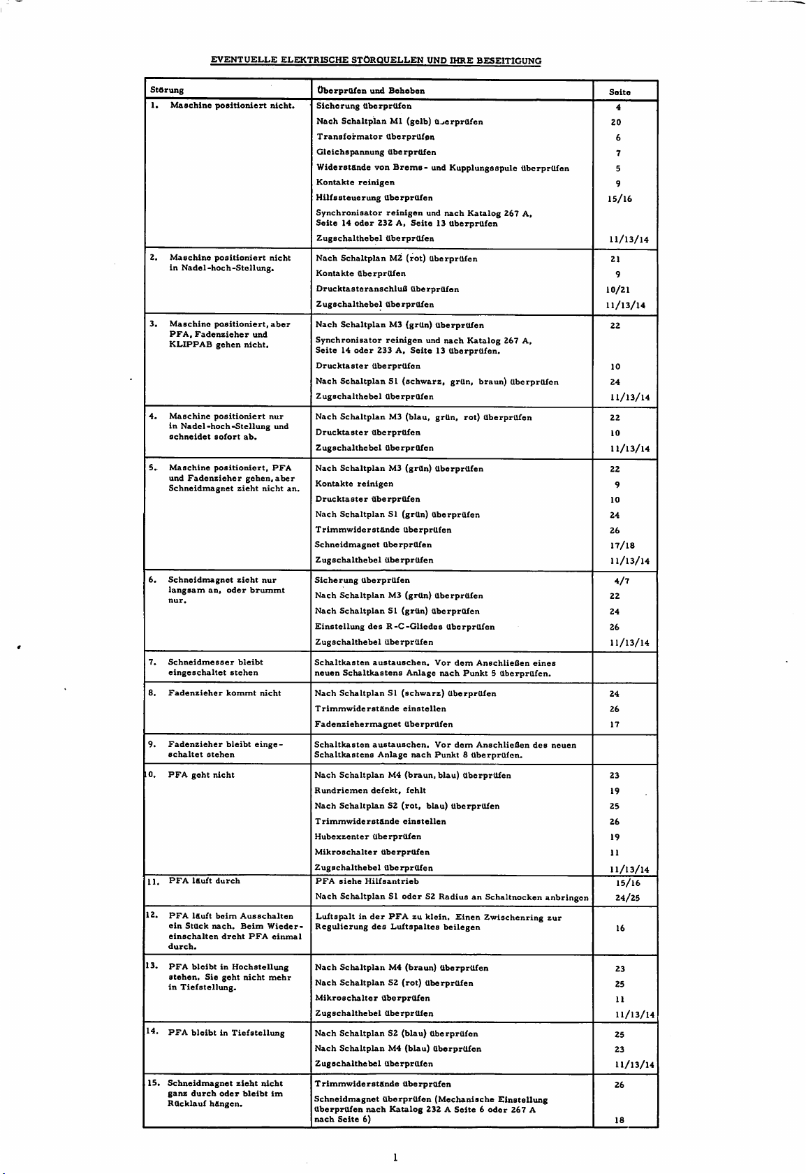
EVENTUELLE
ELEKTRISCHE
STORQUELLEN
UND
IHRE
BESEITIGUNG
StOrung
1.
2.
3.
4.
S.
Schneidmagnet
6.
Schneidmagnet
langsam
nur.
7.
Schneidmesser
eingeschaltet
8.
Padenzieher
9.
Padenzieher
schaltet
10.
PPA
11.
PPA
12.
PPA
ein
einschalten
durch.
13.
PPA
stehen.
in
14.
PFA
15.
Schneidmagnet
ganz
Rttcklauf
Maschlne
Maschine
in
Maschine
PFA,
KL.1PPAB
Maschine
in
schneidet
Maschine
und
Nadel-hoch-Stellung
Tiefstellung.
positioniert
positioiiiert
Nadel-hoch-Stellung.
positioniert,
Padenzieher
gehen
und
nicht.
positioniert
sofort
ab.
positioniert,
Padenzieher
geht
ittuft
Iduft
Stuck
bleibt
gehen,
zieht
zieht
an,
oder
bleibt
stehen
kommt
bleibt
stehen
nicht
durch
beim
Ausschalten
nach.
Beim
dreht
PPA
in Hochstellung
Sie
geht
nicht
brummt
bleibtinTiefstellung
Oder
h&ngen.
zieht
bleibt
durch
nicht
nur
nicht
einge
nicht
nicht.
nicht
aber
nur
und
PFA
aber
Wieder-
einmal
mehr
im
OberprUfen und
Sicherung
Nach
Transformator
Gleichspannung
WiderstUnde von
Kontakte
Hilfssteuerung
Synchronisator
Seite14Oder
Zugschalthebel
Nach
Kontakte
DrucktasteranschluU
Zugschalthebel
Nach
Synchronisator
Seite14oder
Drucktaster
Nach
Zugschalthebel
Nach
Drucktaster
Zugschalthebel
Nach
Kontakte
an.
Drucktaster
Nach
TrimmwiderstUnde
Schneidmagnet
Zugschalthebel
Sicherung
Nach
Nach
Einstellung
Zugschalthebel
Schaltkasten
neuen
Nach
TrimmwiderstUnde
Padenziehermagnet
Schaltkasten
Schaltkastens
Nach
Rundriemen
Nach
TrimmwiderstUnde
Hubexzenter
Mikroschalter
Zugschalthebel
PPA
Nach Schaltplan SI
Luftspaltinder
Regulierung
Nach
Nach
Mikroschalter
Zugschalthebel
Nach
Nach
Zugschalthebel
TrimmwiderstUnde
Schneidmagnet
UberprUfen
nach
Beheben
OberprUfen
Schaltplan
Ml (gelb) U_ierprUfen
OberprUfen
OberprUfen
Brems-
reinigen
OberprUfen
reinigen
232A,Seite13OberprUfen
und
OberprUfen
SchaltplanM2(rot)
OberprUfen
OberprUfen
OberprUfen
Schaltplan
M3 (grUn) OberprUfen
reinigen
233 A,
OberprUfen
und
Seite13OberprUfen.
SchaltplanSI(schwarz,
OberprUfen
SchaltplanM3(blau,
OberprUfen
OberprUfen
Schaltplan
M3 (grUn) OberprUfen
reinigen
OberprUfen
Schaltplan
SI (grUn) UberprUfen
UberprUfen
UberprUfen
UberprUfen
UberprUfen
Schaltplan
Schaltplan
des
R-C-Gliedes
M3 (grUn)
SI (grUn)
UberprUfen
austauschen.
Schaltkastens
Anlage
SchaltplanSI(schwarz)
einstellen
UberprUfen
austauschen.
Anlage
nach
SchaltplanM4(braun,
defekt,
fehlt
SchaltplanS2(rot,
blau)
einstellen
UberprUfen
UberprUfen
UberprUfen
siehe
Hilfsantrieb
oder
S2 Radius an Schaltnocken
PPAzuklein.
des
Luftspaltes
SchaltplanM4(braun)
SchaltplanS2(rot)
UberprUfen
UberprUfen
UberprUfen
SchaltplanS2(blau)
SchaltplanM4(blau)
UberprUfen
UberprUfen
UberprUfen
nach
Katalog
Seite
6)
232ASeite6oder
und
Kupplungsspule
nach
Katalog
OberprUfen
nach
Katalog
grUn,
braun)
grUn,
rot)
OberprUfen
UberprUfen
UberprUfen
UberprUfen
Vor
dem
AnschlieOen
nach
Punkt5UberprUfen.
UberprUfen
Vor
dem
blau)
AnschlieUen
UberprUfen
Punkt8UberprUfen.
UberprUfen
Einen
Zwischenring
beilegen
UberprUfen
UberprUfen
UberprUfen
(Mechanische
OberprUfen
267 A,
267 A,
OberprUfen
eines
des
Einstellung
267
A
neuen
anbringen
zur
Seite
4
20
6
7
5
9
15/16
11/13/14
21
9
10/21
11/13/14
22
10
24
11/13/14
22
10
11/13/14
22
9
10
24
26
17/18
11/13/14
4/7
22
24
26
11/13/14
24
26
17
23
19
25
26
19
11
11/13/14
15/16
24/25
16
23
25
11
11/13/14
25
23
11/13/14
26
18
Page 5
StOrung
16.
Anfangsf&denzulang
(aber
Maschine
justiert).
richtig
UberprUfen
und
Trimmwiderstand
Beheben
1
und2nachjustieren
Seite
26
17.
Maschine
schalten
Positionierdrehzahl.
18.
Maschine
schalten
Positionierdrehzahl
schneidet
drehung.
19.
Beim
Motors
zieher
20.
DrUckerfufl
Fadenzieher
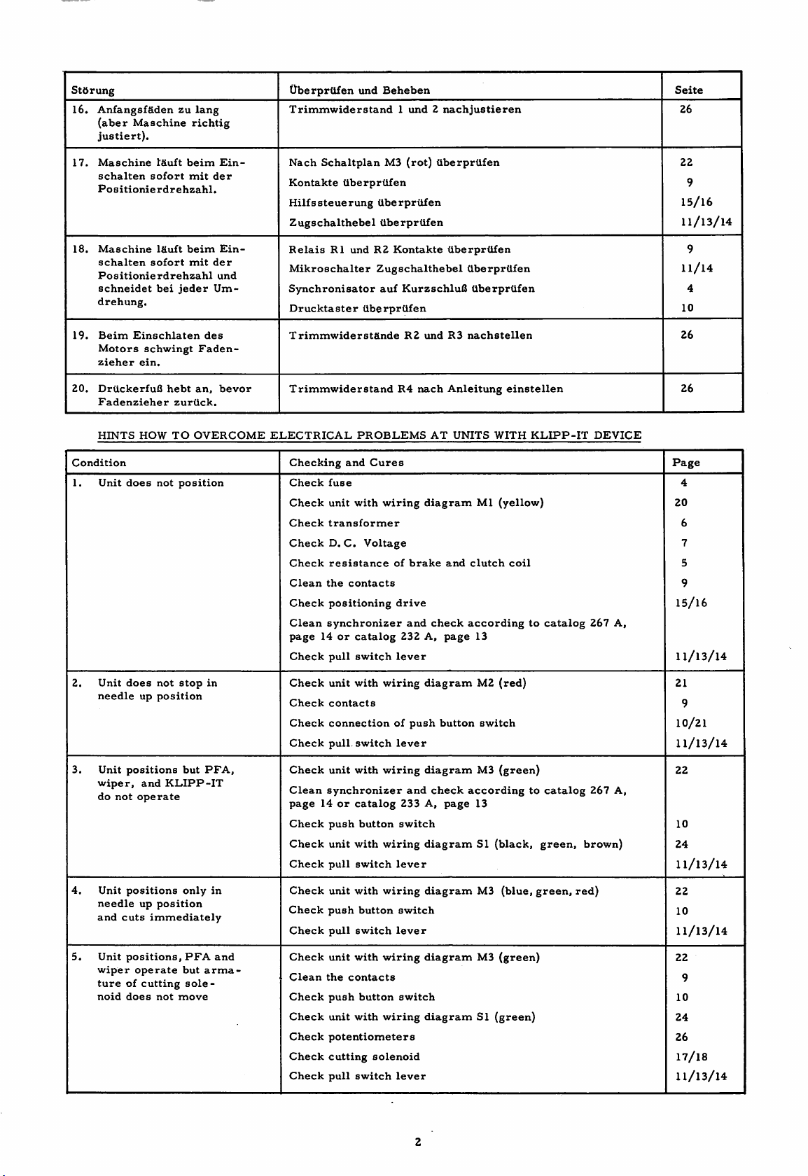
HINTS
Condition
1.
Unit
sofort
sofort
Einschlaten
schwingt
ein.
HOW
does
I'duft
Ifiuft
bei
not
jeder
hebt
zurtick.
TO
position
beim
mit
der
beim
mit
der
und
Um-
des
Faden-
an,
OVERCOME
Ein-
Ein-
bevor
Nach
Schaltplan
Kontakte
Hilfssteuerung
Zugschalthebel
Relais
Mikroschalter
Synchronisator
Drucktaster
TrimmwiderstUnde
Trimmwiderstand
ELECTRICAL
Checking
Check
Check
Check
Check
Check
Clean
Check
Clean
page14or
Check
UberprUfen
UberprUfen
R1
undR2Kontakte
Zugschalthebel
UberprUfen
PROBLEMS
and
Cures
fuse
unit
with
transformer
D.C.
Voltage
resistance
the
contacts
positioning
synchronizer
catalog
pull
switch
M3
(rot)
UberprUfen
auf
KurzschluU
R2
und
R4
nach
wiring
diagram
of
brake
drive
and
232A,page
lever
dberprtlfen
UberprUfen
UberprUfen
R3
nachstellen
Anleitung
AT
UNITS
and
clutch
check
according
UberprUfen
einstellen
WITH
Ml
(yellow)
coil
13
KLIPP-IT
to
catalog
DEVICE
267
22
9
15/16
11/13/14
9
11/14
4
10
26
26
Page
4
20
6
7
5
9
15/16
A,
11/13/14
2.
Unit
needle
3.
Unit
wiper,
do
4.
Unit
needle
and
5.
Unit
wiper
tureofcutting
noid
does
positions
not
positions
cuts
positions,
operate
does
not
up
position
and
KLIPP-IT
operate
up
position
immediately
not
stop
but
only
PFA
but
sole
move
in
PFA,
in
and
arma
Check
unit
Check
contacts
Check
connection
Check
pull,
Check
unit
Clean
synchronizer
page14or
Check
push
Check
unit
Check
pull
Check
unit
Check
push
Check
pull
Check
unit
Clean
the
Check
push
Check
unit
Check
potentiometers
Check
cutting
Check
pull
with
switch
with
catalog
button
with
switch
with
button
switch
with
contacts
button
with
switch
wiring
of
lever
wiring
233A,page
switch
wiring
lever
wiring
switch
lever
wiring
switch
wiring
solenoid
lever
push
and
diagram
button
diagram
check
diagram
diagram
diagram
diagram
M2
(red)
switch
M3
(green)
according
13
SI
(black,
M3
(blue,
M3
(green)
SI
(green)
to
green,
green,
catalog
267
brown)
red)
21
9
10/21
11/13/14
22
A,
10
24
11/13/14
22
10
11/13/14
22
9
10
24
26
17/18
11/13/14
Page 6
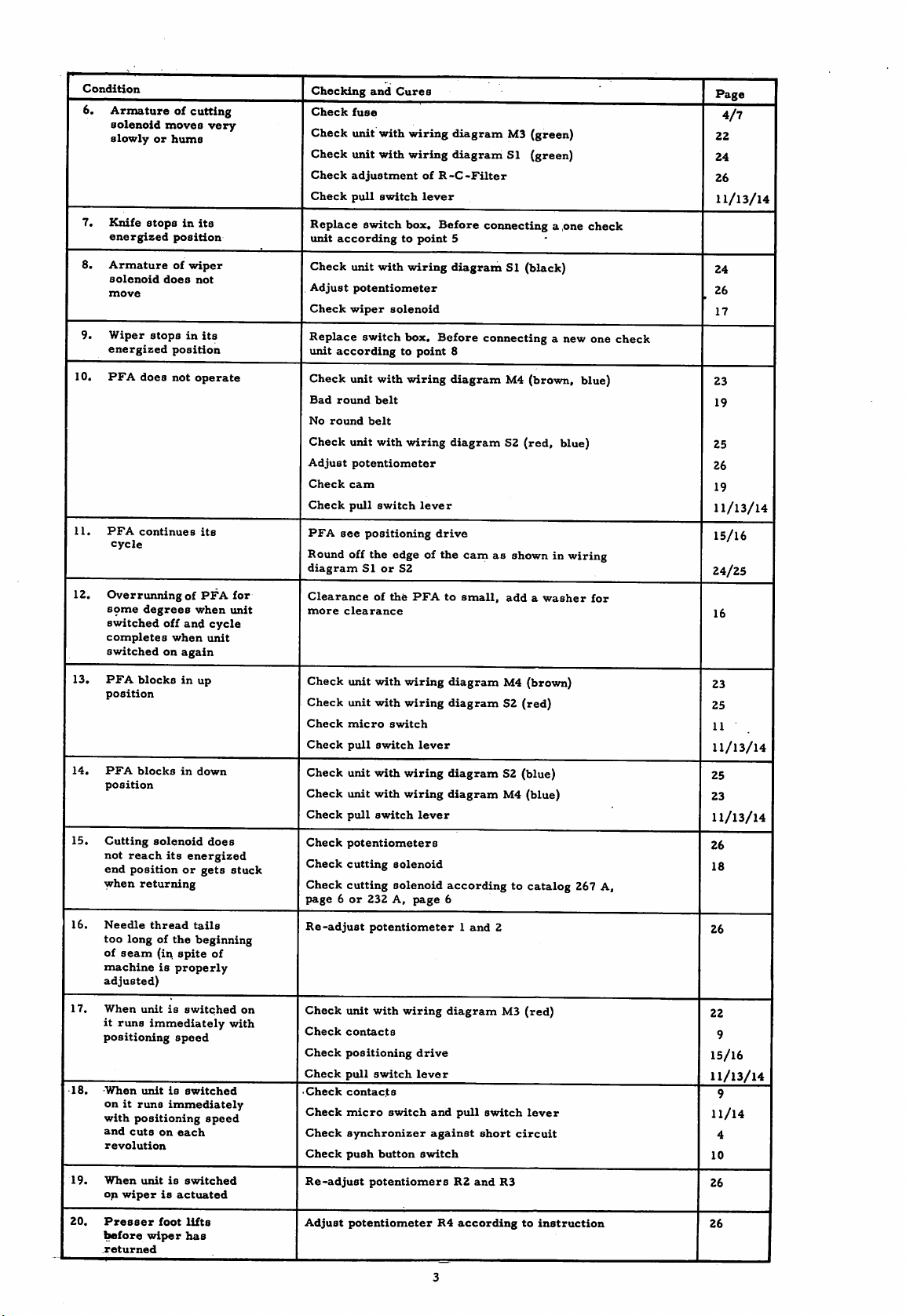
Condition
6.
Armatureofcutting
solenoid
slowlyorhums
7.
Knife
energized
8.
Armatureofwiper
solenoid
move
9.
Wiper
energized
10.
PFA
does
11.
PFA
continues
cycle
12.
OverrunningofPFA
some
degrees
switched
completes
switchedonagain
moves
stopsinits
position
does
not
stopsinits
position
not
operate
when
off
and
when
its
very
cycle
unit
for
unit
Checking
Check
Check
Check
Check
Check
Replace
unit
Check
Adjust
Check
Replace
unit
Check
Bad
No
Check
Adjust
Check
Check
PFA
and
Cures
fuse
unit
with
wiring
unit
with
wiring
adjustment
pull
switch
switch
box.
accordingtopoint
unit
with
wiring
potentiometer
wiper
solenoid
switch
box.
accordingtopoint
unit
with
wiring
round
belt
round
belt
unit
with
wiring
potentiometer
cam
pull
switch
see
positioning
of
R-C-Filter
lever
Before
Before
lever
drive
Round off the edge of the
diagram
Clearance
more
SIorS2
clearance
of
the
PFAtosmall,
diagramM3(green)
diagram
5
SI
(green)
connecting
a ,one
diagramSI(black)
connecting
a new one
8
diagram
M4
(brown,
diagramS2(red,
camasshown in
addawasher
blue)
wiring
check
blue)
for
Page
4/7
22
24
26
11/13/14
24
. 26
17
check
23
19
25
26
19
11/13/14
15/16
24/25
16
13.
PFA
position
14.
PFA
position
15.
Cutting
not
reach
end
positionorgets
when
16.
Needle
too
longofthe
of
seam
machineisproperly
adjusted)
17.
When
it
runs
positioning
-18.
-When
onitruns
with
positioning
and
cuts
revolution
19.
When
op
wiperisactuated
blocksinup
blocks
in
down
solenoid
its
energized
returning
thread
tails
beginning
(in
spite
unitisswitched
immediately
speed
unitisswitched
immediately
on
each
unitisswitched
does
of
speed
stuck
on
with
Check
Check
Check
Check
Check
Check
Check
Check
Check
Check
page6or
Re-adjust
Check
Check
Check
Check
•
Check
Check
Check
Check
Re-adjust
unit
with
wiring
unit
with
wiring
micro
switch
pull
switch
lever
unit
with
wiring
unit
with
wiring
pull
switch
lever
potentiometers
cutting
solenoid
cutting
solenoid
232 A,
page
potentiometer1and
unit
with
wiring
contacts
positioning
pull
contacts
micro
switch
switch
drive
lever
synchronizer
push
button
switch
potentiomers
diagram
M4 (brown)
diagramS2(red)
diagramS2(blue)
diagram
M4
accordingtocatalog
6
2
diagram
and
against
R2
pull
switch
short
and
M3
circuit
R3
(blue)
(red)
lever
23
25
11
11/13/14
25
23
11/13/14
26
18
267 A,
26
22
9
15/16
11/13/14
9
11/14
4
10
26
20.
Presser
tefore
returned
foot
wiper
lifts
has
Adjust
potentiometer
R4
accordingtoinstruction
26
Page 7
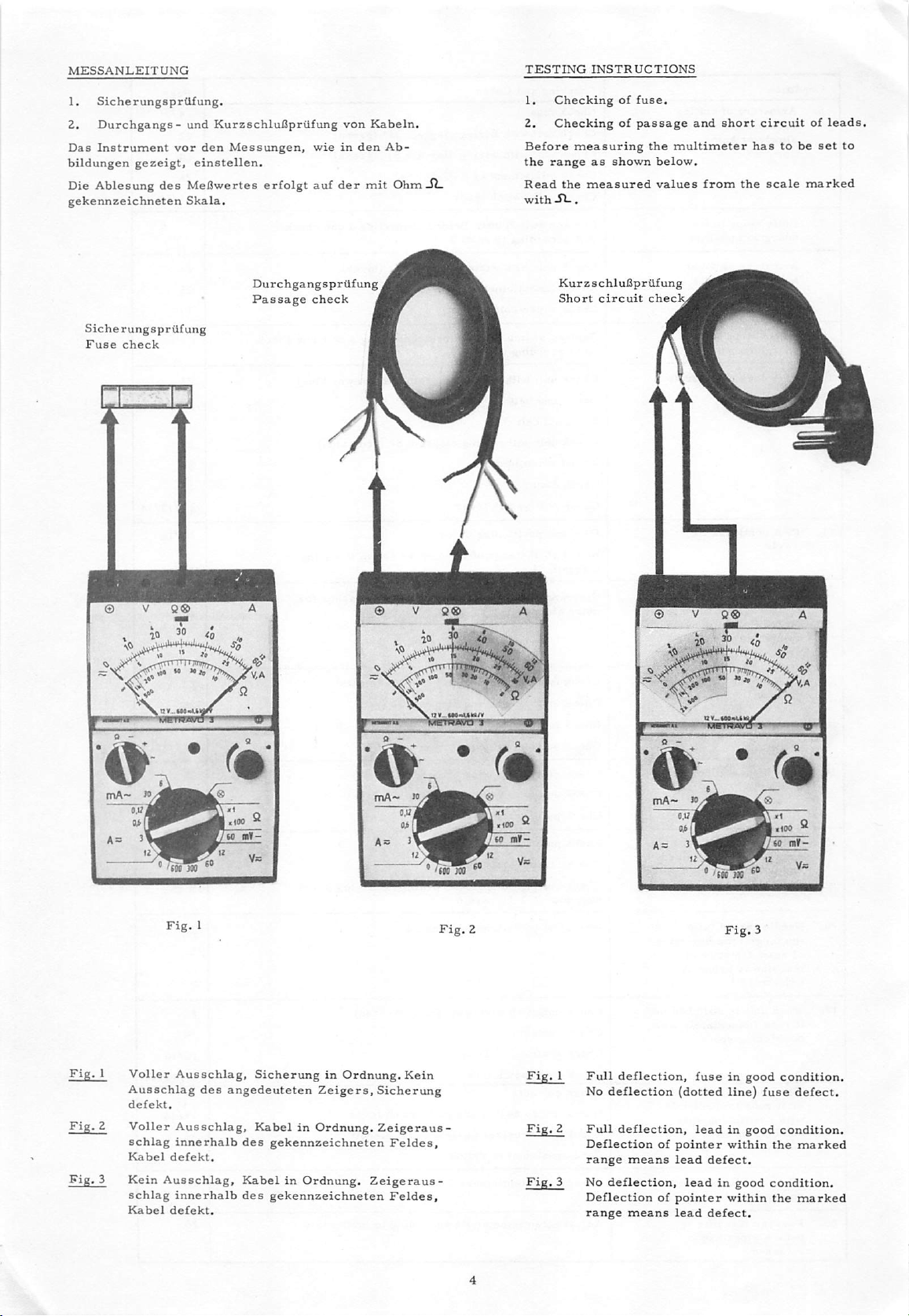
MESSANLEITUNG
1.
SicherungsprUfung.
2.
Durchgangs-
Das
Instrument
bildungen
gezeigt,
und
Kurzschlufipriifung
vor
den
Messungen,
einstellen.
wieinden
Die Ablesung des Mefiwertes erfolgt auf
gekennzeichneten
Skala.
von
der
Kabeln.
Ab-
mil
Ohm
JL
TESTING
1.
2.
Before
the
Read
with
INSTRUCTIONS
Checkingoffuse.
Checkingofpassage
measuring
range
as
the
measured
SL.
shown
the
below.
values
and
multimeter
from
short
circuitofleads
hastobe
the
scale
set
marked
to
SicherungsprUfung
Fuse
check
© V
Q®
Durchgangsprtifung
Passage
A
check
1
© V
<i.
Q®
Kurzschluflpriifung
Short
circuit
check
© V
g®
mA-
Voller
Ausschlag
defekt.
Voller
schlag
Kabel
Kein
schlag
Kabel
}o^
^oTir"!r«e
defekt.
Ausschlag,
defekt.
Ausschlag,
des
Ausschlag,
innerhalb
innerhalb
V-
*-
Sicherung
angedeuteten
KabelinOrdnung.
des
gekennzeichneten
KabelinOrdnung.
des
gekennzeichneten
in
Ordnung.
Zeigers,
& '
mA-
»/
Kein
Sicherung
Zeigeraus-
Feldes,
Zeigeraus-
Feldes,
ji
Fig.
Fig.
Fig.
I
Full
No
2
Full
Deflection
range
3 No
Deflection
range
& '
deflection,
deflection
deflection,
means
deflection,
means
fuseingood
(dotted
leadingood
of
pointer
lead
leadingood
of
pointer
lead
® nint
defect.
defect.
line)
within
within
<i
condition.
fuse
defect.
condition.
the
marked
condition.
the
marked
Page 8
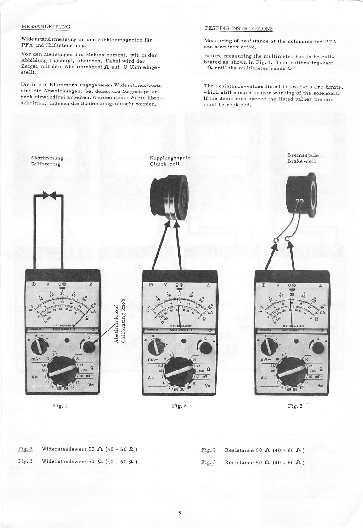
MESSANLEITUNG
TESTING
INSTRUCTIONS
Widerstandsmessung
PFA
und
Hilfssteuerung.
Vor
den
Messungen
Abbildung1gezeigt,
Zeiger
stellt.
Dieinden
sind
noch
schritten,
mit
dem
AbstimmknopfAauf
Klammern
die Abweichungen,
einwandfrei
miissen
Abstimmung
Calibrating
an
das
abeichen.
angegebenen
arbeiten.
die
den
Elektromagneten
Mei3instrument,
Oabei
wird
O Ohm
bei
denen die Magnetspulen
Werden
Spulen
Widerstandswerte
diese
ausgetauscht
fUr
wieinder
der
einge-
Werte
Uber-
werden.
Kupplungs
Clutch-coil
spule
Measuring
and
auxiliary
Before
brated
XI-
until
The
resistance-values
which
still
If
the
deviations
must
be
of
resistance
drive.
measuring
as shown in
the
multimeter
ensure
replaced.
exceed
at
the
the
multimeter
Fig,1.Turn
reads
listedinbrackets
proper
workingofthe
the
listed
solenoids
hastobe
for
calibrating-knot
O
are
solenoids.
values
the
Bremsspule
Brake
-coil
PFA
cali
limits
coil
Fig.
Fig.
© V
0^.
mA-
fo.
2
Widerstandswert
3
Widerstandswert
9®
•
A
50A.(40 - 60XL)
50 A (40 - 60
A.)
© V
9®
& '
inA~
»/
'/fijoP'
/<
Fig.
Fig.
A
Z
3
Resistance
Resistance
© V
As
50 A
(40
9®
®
'tw
JOO
- 60 A )
50 A (40 - 60 A )
A
Page 9
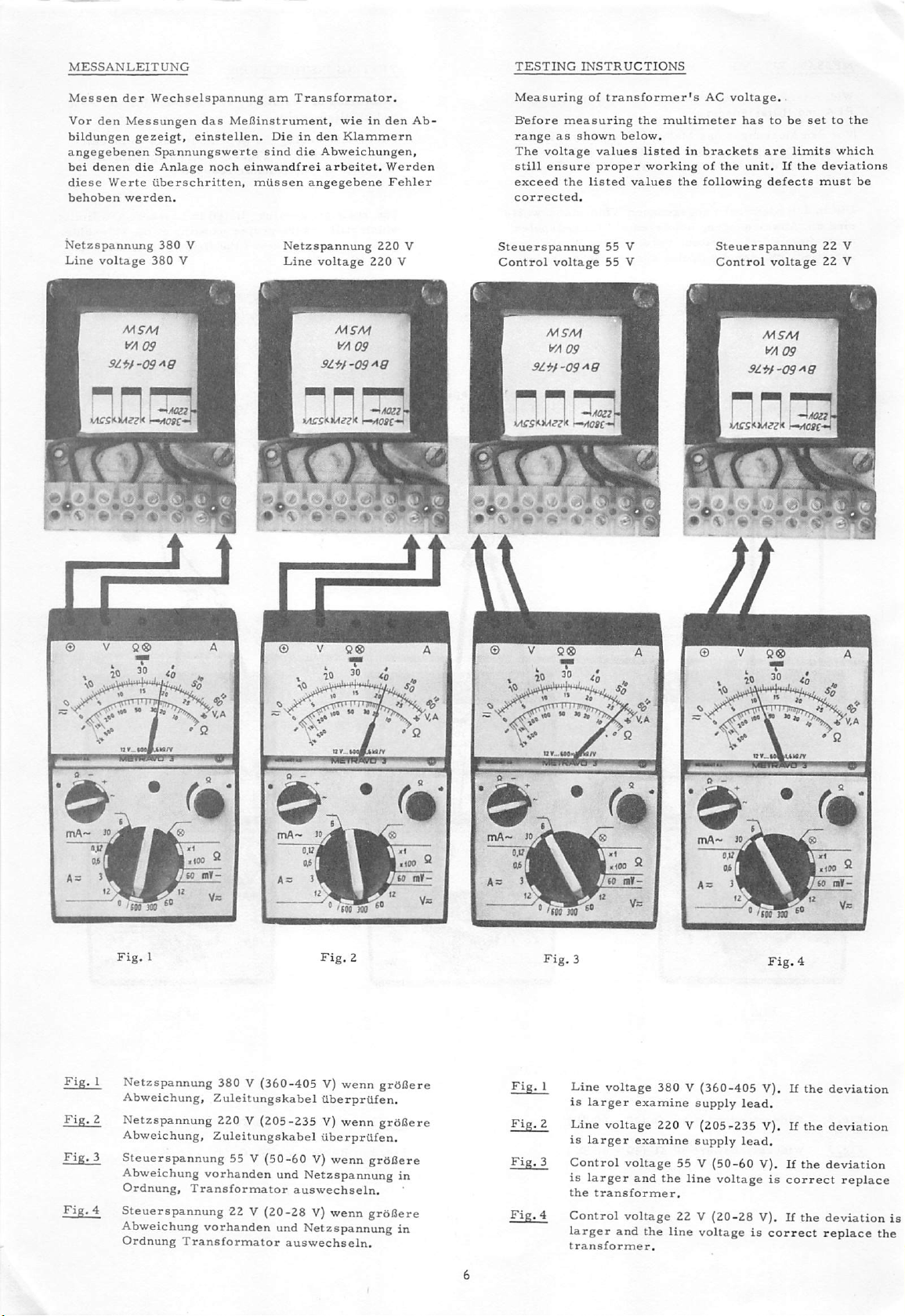
MESSANLEITUNG
TESTING
INSTRUCTIONS
Messen
Vor
bildungen
angegebenen
bei
diese
behoben
Netzspannung
Line
den
denen
Werte
voltage
9i*rf'09^a
der
Messungen
werden.
AIF/Vf
Wechselspannung
gezeigt,
die
einstellen.
Spannungawerte
Anlage
uberschritten,
380
V
380
V
das
Mel3instrument,
noch
einwandfrei
am
Dieinden
sind
mdssen
Netzspannung
Line
Transformator.
wieinden
die
Klammern
Abweichungen,
arbeitet.
angegebene
voltage
MS'A/f
9li^f-09Ag
1 I
220
220
Ab-
Werden
Fehler
V
V
Measuring
Before
range
The
still
exceed
corrected.
Steuerspannung
Control
measuring
as
voltage
ensure
the
voltage
MSM
yA09
91^1-09^9
of
transformer's
shown
values
proper
listed
55 V
55 V
the
multimeter
below.
listedinbrackets
workingofthe
values
the
AC
voltage.
hastobe
unit.Ifthe
following
Steuerspannung
Control
are
defects
voltage
settothe
limits
must
which
deviations
be
22 V
22 V
Netzspannung
Abweichung,
Netzspannung
Abweichung,
Steuerspannung
Abweichung
Ordnung,
Steuerspannung
Abweichung vorhanden und Netzspannung in
Ordnung
380 V (360-405 V)
Zuleitungskabel
220 V (205-235 V) wenn
Zuleitungskabel
55 V (50-60 V) wenn
vorhanden
Transformator
und
22 V (20-28 V) wenn
Transformator
auswechseln.
wenn
tiberprUfen.
(iberprUfen.
Netzspannung
auswechseln.
grOOere
grdflere
grdCere
in
grdBere
Line
voltage
is
larger
Line
voltage
is
larger
Control
is
larger
the
transformer.
Control
larger
transformer.
examine
examine
voltage
and
voltage
and
the
380 V
(360-405
supply
220 V
(205-235
supply
55 V
the
(50-60
line
22 V
(20-28
line
voltageiscorrect
V). If
the
lead.
V). If
the
lead.
V). If the
voltageiscorrect
V). If the
deviation
deviation
deviation
replace
deviation
replace
is
the
Page 10

MESSANLEITUNG
TESTING
INSTRUCTIONS
Messungen
A.
Messen
Vor
dem
Instrument
20 - 25 V
die
Steuerplatte
werden.
B.
(iberpriifen
stromseite.
Vor
dem
Zuleitungskabel
Instrument
Ausschlag
auswechseln.
C.
tiberprufen
Vor
dem
einstellen.
in
das
Ausschlag
Sicherungselement
werden.
innerhalb
der
Priifen
der
Gleichspannung
Mefiinstrument
mufl
einen
ergeben.
Bei
defekt
des
Gleichrichters
PrUfen
muB
vom
auf
MeOinstrument
oO
-Gleichrichter
der
Sicherungselemente
Priifen
Sicherungselement
S67(n7)
Mefiinstrument
Sicherung
innerhalb
defekt
Motorsteuerplatte.
von
22 "V.
A
Zeigerausschlag
anderen
und mufl
Werten
ausgewechselt
auf
B
Transformator
JT.
stehen
defekt.
bleiben.
Motorsteuerplatte
C,
mufi
vorher
eingeschraubt
des
gekennzeichneten
und
(iberpriift
mufi
einstellen.
von
ist
der
Wechsel-
einstellen.
abklemmen.
Anderer
(3, 15 A u.
wie
gezeigt,
sein.
Feldes,
ausgetauscht
und
1,5
A)
Measurements
A.
Measurement
Before
The
are
replaced.
B.
Checking
Before
Supply
The
Other
control-panel.
C.
Checkingoffuse-holders
Before
shown.
before
Deflection
at
measuring
pointer
read
the
of
measuring
lead
pointerofthe
value
measuring
The
and
mounted
within
fuse-holder
the
motor-control-panel.
of
DC
voltage
multimeter
must
show
control-panel
the
rectifier
the
from
multimeter
transformer
instrument
means
defect
multimeter
fuses
mustbechecked
into
the
and
marked
fuse-holder
22 V.
A
20
on
hastobe
- 25 V.Ifother
is
defect
the
AC
mustbedisconnected.
must
rectifier.
(3,
15 A
and
C
hastobe
the
fuse-holders.
range
mustbereplaced.
and
Conner
B
hastobe
stopatoO
Replace
1,5
separately
means
set.
values
hastobe
lions.
set.
motor-
A
set
as
defect
m
RH
R13
R12mR21
(d21)
R22
(322)
Sicherung
3.16^
Sicherf/rig 1,5A
® . V
Q®
ift 30
\
Page 11

MOTORANSCHLUSS
Beim
Anschlufl
des
Kunden
muB
den
gen
entsprechen.
Netz 380 V
geachtet
jeweiligen
Drehstrom
des
Motors
drtlichen
braun
broi^n
werden,
mufi
auf
Der
Sicherheitsbestimmun-
0
I Qetb-grun yellow-green
-Zum
Motorschutzschalter
To
Overload
die
Netzspannung
AnschluB
50/60
switch
Hz
selbst
Erdklemme
Ground
CONNECTION
When
connecting
supply
nection
lations.
voltage
must
Supply 380 V
0
0 «
0
0 C
J
h
k
fSteuertransformator
Transformer
OF
MOTOR
the
with
the
comply
three-phase
9 0
0
0
9 0
0
0
8v
60-im
60
M
wskw
for
motor
check
motor
the
wiring.
local
with
AC 50/60 cycles
0
0
0
0
control
panel
customer's
The
safety
main
con
regu
Netz
220
V
Drehstrom
bfO¥^n
yeiiokv
•Zum
Motorschutzschalter
To Overload switch
50/60
i)
Hz
o o
VErdklemme
fGround
Supply 220 V
0
O 0
0
0
-0-
/Steuertransformator
Transformer
three-phase
0
0
0
0
0
BvSO-UlS
60VA
WS\N
AC
50/60
cycles
0
0
0
0
0
0
^
for
control
panel
Andere
Motor
Netzspannungen
miissen.
Netzspannungen
und
Steuertransformator,
entsprechend
erfordern
einen
die
den
angeschlossen
speziellen
vorhandenen
werden
Other
line
trol
transformers.
dingtothe
voltages
existing
require
They
main
special
havetobe
supply
voltages.
motors
connected
and
con
accor
Page 12

MESSANLEITUNG
1.
Reinigen
Nach
ISngerer
Kontakten
der
mittels
starker
(kein
Schmirgelpapier)-entfernt
2.
Justieren
Die
Relais
drei
verschiedenen
"Schliefler",
FUR
der
Kontakte;
Einsatzzeit
durch
Funkenbildung
eines
Verbrennung
der
Kontakte;
sind
bei
"Wechsler".
RELAIS
Putztuches
mit
F3
Union
Kontakten
bildet
einem
sich
ein
Rtlckstand,
-
eventuell
Polierpapier
werden
Schaltkasten
bestttckt:
auf
den
bei
mui3.
mit
"Offner'
TESTING
1.
Cleaning
Afteralong
burnt
meansofcloth.
(do
not
2.
Adjusting
The
different
"normally
INSTRUCTIONS
of
the
working
marks.
relays
Small
use
emery-paper).
of
the
ofF3Union
contact
open",
FOR
contacts:
period
marks
Deeper
contacts;
arrangements,
marks
control
"change
RELAY
the
contacts
canbecleaned
mustbepolished
box
have
"normally
over
contact".
show
by-
three
closed",
Die
Bezeichnung
takt
"tut",
Abstdnde
?oll
bei
De-energized
Schaltzelchen
wenn
siehe
seinem
Ruhestellung
Arbeits-
siellung
Enefgized
Legend
des
Kontaktes
das
Relais
Fig.1.Der
halben
Weg
Offner
Normally
gibt
schaltet.
Schaltkontakt
stehen
an,
wie
cbsed
n
VT
Intm
o—o
was
der
Die
erforderlichen
des
Fig.2zeigt.
contact
Kon-
Wechslers
O^Smm
Schliesser
Normally
fl
Fig.
1
O.Smrn
open
contact
n
cr—
The
terms
relayisnot
giveninFig.1.In
change
the
over
other
Change
specify
energized.
contact
contacts
Wechsler
over contact
IfT
o
the
contact
the
change
must
as
showninFig.
The
opening
rest
position
over
half
when
widths
arrangement
wayinbetween
2.
the
are
the
Fig.
2
Die
Justierung
tuellanden
Damit
ein
der
ruhende
nach
dem
erfolgtanden
Kontaktzungen.
gewisser
Kontakt,
Bertihren
Kontaktdruck
durch
noch
den
etwas
Andriickfedern,
vorhanden
bewegenden
mitgenommen
even
ist,
mufi
Kontakt
werden.
Adjust
insufficient
To
contact
contact.
the
gurantee
must
contacts
bend
enough
be
the
bent
with
contact
contact
slightly
the
springs.
leafs.
pressure,
by
the
If
still
the
switching
resting
Page 13

MESSANLEITUNG
aen
Messungen
Idung
gezeigt,
aas
meuinstrumenr,
einstellen.
wieinaer
X
TESTING
Deiore
to
the
INSTRUCTIONS
measuring
range
as
tne
shown
multimeter
below.
t
Priifung
Zeiger
ausgezogener
Priifung
jeder
(angedeuteter
e
t^T
sich
nriirktaRt*»r
des
muB
des
Zeiger
ein
Drucktasters
sichimweiBen
Zeiger).
Drucktasters
muB
sich
Zeiger).
anderes
Meflergebnis
Hefekt.
im
® V
in
Ruhestellung,
Feld
in
gedruckter
dunklen
zeigen,
Q®
befinden
Feld
jeder
(veil
Stellung,
befinden
dann
1.
Checking
All
pointers
shown
2.
Checking
position.
range
Ifadifferent
is
defect.
V
t 10
'X
^ '
tnA-
0 6«
of
the
push-button
must
full
the
pointers
beinthe
line).
push-button
with
is
experienced
with
(as
of
All
shown
result
/<
must
dotted
wh
be
I
i
m
I
in
in
lii
Page 14

MESSANLEITUNG
TESTING
INSTRUCTIONS
I O
Sollte
der
Sc
mA~
n
Page 15

MESSBLATT
Mit
Schraube
Hilfssteuerung
A
wird
justiert.
der
Mikroschalter
Zugschalthebel
ADJUSTING
INSTRUCTIONS
B
fdr
die
The
be
micro
adjusted
switch
by
screw
for
the
A.
positioning
drive
can
Mit
der
Mikroschalter8
vorgang
Bei
SchraubeBwird
justiert.
der
Einstellung
fttr
PedalinRuhestellung
EINSTELLUNG
1.
SchraubeAim
DER
riemenscheibe
2.
Schraube
bis
weiteren
Schraube
EINSTELLUNG
1.
Schraube
in
2.
Schraube
fuQ
ist
entgegen
Riemenscheibe
halben
richtig
DER
soweit
Hochstellung
wieder
senkt;
die
nach
SchraubeBrichtig
der
PFA
Einschaltpunkt
und
die
istzubeachten,
steht.
SCHRAUBE
Uhrzeigersinn
mit
ca.
200
dem
Uhrzeigersinn
still
bis
steht.
ganzen
eingestellt.
SCHRAUBE
herausdrehen
geht.
hineindrehen
einer
weiteren
eingestellt.
ftir
den
daU
A
drehen
U/min.
Nach
Umdrehung
B
bis
DriickerfuB
bis
sich
halben
des
Abschneid-
das
bis
lauft.
drehen,
einer
ist
Drdcker-
Umdrehung
Motor-
die
By
means
the
micro
for
the
cutting
When
adjusting
rest
position.
ADJUSTMENT
1.
Turn
motor
2.
Turn
stops.
screwisadjusted
ADJUSTMENT
1.
Loosen
2.
Turninthe
again.
is
adjusted
of
screwBthe
switchisadjusted
process.
take
care
OF
SCREW
screwAclockwise
runs
with
approximately.
screw
After
counter
further
clockwise
halftofull
correctly.
OF
SCREW
screw
until
presser
screw
After
until
further
correctly.
switching
for
that
the
A
until
B
the
half
revolution
moment
the
treadle
belt
until
foot
presser
PFA
and
is
pulley
200
RPM.
belt
revolution
lifts.
foot
screw
of
in
of
pulley
the
lowers
B
13
Page 16

W
cn
s
r
Z
>
CO
w
Z
H
G
o
N
c
oq
A
A
W
H
hH
H
z
CO
o
H
z
CO
»
G
hH
H
n
o
§
V
O
c
•O
screw
Einstellschraube
Adjusting
lever
Zugschalt-
dargestellt.
switch
vom
pull
position.
of
Zustand
Schalter
der
removed
switches
of
in
ausgebauten
im
shown
Diagram
is
hebel
Schaltstellung
Achtung;
Attention;
B
B
screw
Adjusting
[Adj
/HEinstellschravibe
/
f.Vj^
\
I •
/
Page 17

HILFSANTRIEB
Der
Hilfsantrieb
magneten
eine
einer
und
Ankerscheibe
FUhrung
Kupplungsmagnet
eine
Antriebsscheibe
zwei
Umlenkrollen
latorseite
fUhrung
Kohlen
stehend.
NcLhmaschine
tlber
und
keit
wird
im
Loslassen
am
Stellung)
des
f(ir
den
ttber
zwei
Beim
die
Ankerscheibe
die
drehbare
angetrieben.
durch
Zughebel
BettLtigung
bzw.
des
Synchronisator
die
Stromzufiihrung
Hilfssteuerung
Nadelstellung
Die
Isolierstelle
Relais
und
steuerung
festhult.
mdglich,
den
Kupplungsmagneten
gleichzeitig
und
Bei
einen
kurzer
besteht
dem
mit
Hauptmotors
Kupplungsmagneten
Schleifringe.
Einschalten
Uber
Bremsscheibe
Fufipedals
aus
Bremsmagneten,
auf
der
geringem
ist
drehbar.
und
von
einer
den
eingeschalteten
-
die
Der
Kupplungsmagnet
des
Zugschalthebel
befindliche
unterbricht.
erreicht.
des
Synchronisators
den
Bremsmagneten
damit
die
Nfihmaschineinder
BetUtigung
Stich
auszufUhren.
zwei
verlfingerten
Seitenspiel
Er
wird
mit
Schnurscheibe
angetrieben.
Der
der
Hilfssteuerung
Schnecke
mit
FuOpedals
wieder
ausgeschaltet,
Isolierstelle
des
Kupplungsmagneten
Hierdurch
der
des
Magneten,
zwischen
Schneckenwelle
besitzt
einem
eingeschaltet
bewegt.
auf
Rundriemen
Die
erfolgt
Bremsmagnet
Kupplungsmagneten
-
das
niederer
der
(iber
den
wird
schaltet
Hilfssteuerung
ein,
der
Fudpedals
dem
Kupplungs-
denen
sich
Der
der
Stirnseite
auf
der
Venti-
Stromzu-
durch
zwei
ist
fest-
wird
die
Schneckenrad
Geschwindig-
Hilfssteuerung
Mikroschalter
und
beim
sobald
(Nadel-tief-
der
die
gewiinschte
Uber
ein
aus
die
Hilfs
Soll-Stellung
ist
es
(iber
die
AUXILIARY
The
auxiliary
noid
and
in
themina guiding
side
playonan
solenoid
a
drive
guide
the
main
by
two
noidisstationary.
the
sewing
-
turned-on
worm
noidofthe
sewing
within
off
again
the
contact
interrupts
auxiliary
thus
attained.
The
contact
a
contactor
while
stops
in
the
pedal
DRIVE
drive
brake
solenoid,
extensionofthe
is
rotable.
pulley,
rollers
carbon
driven
by a
motor.
brushes
machineisput
clutch
wheel,
and
auxiliary
machine
the
pull
lever
when
the
pathofthe
the
power
control.
gaponthe
the
simultaneously
the
wanted
shortly,
clutch
auxiliary
position.
itispossible
consistsoftwo
witharotor
arrangement
magnets,
withasmall
worm
On
its
front
by
means
rope
pulley
Powerissuppliedtothe
over
When
the
solenoid,
the
rotable
controlisturned
pedalbywayofthe
resp.
pedalisreleased,
synchronizer
supplytothe
The
wanted
synchronizer
solenoidofthe
turning
control
When
enditis
of a
disposedonthe
two
sliprings.
auxiliary
into
slow
the
rotor
brake
pull
switch
clutch
needle
on
the
and
thus
actuating
to
makeasingle
round
motionbywayofthe
disk,
disk.
micro
as
(needle
turns
brake
the
disk
moving
between
amount
shaft.
The
clutch
equipped
clutch
controlisturned
The
onbyactuating
lever,
soonasthe
solenoidofthe
down
auxiliary
sewing
the
clutch
belt
over
fan
solenoid
The
brake
the
worm
clutch
switch
offbyway
solenoid
disposed
andisturned
down
position)
position
control,
machine
sewing
stitch.
side
machine
sole
of
with
and
gab
is
which
two
of
sole
on,
sole
the
in
of
Housing
Motorgehause
Rundriemen
Roundbelt
Spacing washer to adjust
clearance
Zwischenring z.i?egulierungd.Luftspolt
Antriebswelle
Drive
Shaft
Abdeckring Washer
Schleifring
f.Kohien
KuppLungsmogn^
KygelLager
Jsolierscheibe Jnsulating washer
BefestigungssdraiAoe
Holdingscrew
Bremsdouer
Permanent
magnet
magnet
Bremsmagnet
Brake
Band
/or
Clutch
Boll bearings
Anker
Clutch
Korkt)elag Cork-lining
Mitnehmeritzel
Jsolierscheibe
Sich&vngsscheibe
Lock
solenoid
brushes
solenoid
plate
wadKr^
Pinion
Jnsulating
nwftflrl
kohlen
Brushes
Hohlenkappen
Caps
Halteschraube
f.fy-emsmognet
Abdeckhaube
Cover
Connecting coble
Anschlu&kabel
ktemmbrettdeckel
Terminal
cover
Holding
screw
broke
solenoid
for
Hlemmbrett
Terminal
15
Page 18

uberprOfung
1.
Hilfsantrieb
2.
Korkbelag
Magnetkupplung,
und
3.
Der
Ankers
groder
4.
Brems-
UberprUfen.
5.
Luftspalt
0, 5
Luftspalt
0, 5
Einstellung
siehe
Kupplung
Korkbelag
ca.0,3
Abnutzung
und
zwischen
mm.
Fig.
zwischen
mm.
Fig.
Fig.1und
per
hilfssteuerung
zerlegen.
des
Ankers,
Anlauffl&che
reinigen.
mudander
mm
(Iberstehen.
Anker
Kupplungsmagnet
Anker
1.
Anker
2.
des
Luftspaltes
2.
Schleifbahnen
der
Stirnseite
austauschen.
und
und
Bei
nach
Bremsmagnet
Kupplungsmagnet
durch
Zwischenring,
der
Bremse
des
Seite
CHECKING
1.
Disassemble
2.
Clean
relating
bands
3.
The
clutch
If
clutch
5
4.
5.
Check
Clearance
0, 5
Clearance
0, 5
Adjustmentofclearance
washer,
the
the
of
cork
cork
plate.
brake
mm
mm
THE
AUXILIARY
auxiliary
cork
liningofclutch
facesofbrake
solenoid
lining
must
plate
for
approx.
liningisworn
and
between
(0, 02")
between
(0,
02")
see
Fig.1and
clutch.
clutch
clutch
Fig.
clutch
Fig.
drive.
and
clutch
project
0, 3
the
mm
more,
solenoidasper
plate
1.
plate
2.
by
meansofspacing
2.
plate
with
and
faceofthe
(0,
012").
replace
and
brake
and
clutch
the
contact
page
solenoid
solenoid
5,
Zwischenringz.
Regulierung d.
Luftspaltes
Spacing
Wa^r
adjust
to
clearance
EingekuppeLte
Engaged
kupplungsmagnet
Clutch
solenoid
Luftspalt
Clearance
Stellung
position
0,020indi
if,5
Bremsmagnet
Broke
Anker
Outchpiate
mm
solenoid
Zwischenring z.
Pegulierung d.
Luftspaltes
Spacing
washer
adjust
clearance
to
Ai/sgekuppeLte
Disengaged
stellung
position
opzoinch
0.5
Luftspalt
Clearance
Bremsmagnet
Brake
'Anker
ClubchptQte
mm
solenoid
Fig.1
16
Fig.Z
Page 19

TESTING
INSTRUCTIONS
Messen
Fadenzieher
Vor
auf
Dieinden
die
einwandfrei
ten,
der
dem
Seite5gezeigl.
Abweichungen,
mussen
Innenwiderstfinde
magnet.
Priifen
MelJinstrument
Klammern
arbeiten.
die
Magnete
Schneidmagnet
Cutting
angegebenen
bei
denen
Werden
ausgewechselt
Solenoid
von
abgleichen,
die
Magnete
die
Schneid-
Ohmwerte
Werte
und
wie
sind
noch
aberschrit-
werden.
Measuring
and
wiper.
Before
brated
The
as
Ohm-values
ensure
the
measured
must
be
o£
resistances
measuring
explained
proper
operating
values
replaced.
Fadenzieher
Wiper
the
on
listed
of
multimeter
page
in
brackets
of the
exceed
magnet
Solenoid
solenoid
5.
rotary
the
limits
has
are
for
the
to be
cali
limits
solenoids.
the
solenoids
cutter
which
If
\
Fig.
1
Spulenwiderstand
Fig.
2
Spulenwiderstand
1,47
31,4^
(1,37
(28-34
-
Fig.
Fig.
I
Resistanceofcoil
2
Resistance
l,475i
of
coil
31, 4-S2 (28 - 34 iJ- )
(1,37-1,52-5^
)
Page 20

MESSANLEITUNG
Messen
1.
2,
3.
4,
der
Widerstand
ilberprUfen.
Keilriemen
Pedal
nach
Maschine
drehen.
muB
Meesinstrument
zeigen.
wohl
dae
der
Magnet
Einstellung
anleitung
justieren.
Bringt
austauschen.
Schneidmagnetspannung
dee
Schneidmagneten
der
Motorriemenscheibe
rtlckwarts
langaam
Kurz
vor
treten.
von
Nadeltie£
Nadelhoch
einen
Zieht
der
Meesinstrument
Uberprilfen
das
keinen
Schneidmagnet
mechanisch
des
Schneidmagneten
and
Erfolg,
nichtinOrdnung.
gegebenenfalls
(Seite
entfernen.
nach
(ca,
3-4
Zeigerausschlag
dann
Schneidmagnet
nicht
nach
ausschlfigt,
17)
Nadelhoch
mm)
an,
ob-
so
ist
Juetier-
TESTING
Testing
1.
2.
3.
4.
INSTRUCTIONS
the
voltageofcutting
Check
coil
(page
Remove
Heel
Turn
to
needle-up
(approx.
multimeter
mechanism
deflection,
fault.
accordingtoadjusting
if
necessary.
If no
solenoid.
resistanceofcutting
17).
V-belt
the
pedal.
the
handwheel
l/8"
the
Check
successisachieved
solenoid.
solenoid
from
motor-pulley.
slowly
from
needle-down
position.
Just
before
- 5/32"), the pointer of the
must
deflect.Ifthe
does
not
moveinspiteofpointer
mechanism
adjustmentofcutting
instructions
cutting
hasamechanical
replace
up-position
mechanism
and
readjust
cutting
Iw
a.
mA-
ovM
wll
f
10 ,
Q9
*
Page 21

JUSTIERANLEITUNG
(PrefierfuIJautomatik)
mit
schematischem
FOR
Schaltbild.
PFA
ADJUSTING
(Presser
with
wiring
INSTRUCTIONS
Foot
Automatic)
diagram.
FOR
PFA
Justiermhglichkeit
1.)
Deckel
2.)
Zylinderschraube
3.)
Gewiinschte
scheibe
nockens
4.)
Zylinderschraube
5.)
Deckel
SiecKer
/
der
2
abnehmen.
Arbeitsstellung
1
durch
4
einstellen.
2
befestigen.
Kurbelscheibe
3
lockern.
Verdrehen
3
wieder
der
Kurbel
des
Schalt-
anziehen.
1
Adjusting
1.)
2.)
3.)
4.)
5.)
Possibility
Remove
Loosen
Adjust
by
turning
Retighten
Attach
cover
Allen
crank
the
Allen
cover
of
Crank
2 .
screw
3 .
disctodesired
cam
4 .
screw
3 .
2 .
Disc
ox
1
working
O V
position
Hubeinstellung
Range of
Hubeinstellung
crank
von
6-32
pin
adjustment
des
mm
Kurbelzapfens
l/4"-l
-)
l/4"
10
Adjustment
of
Crank
Pin
10
1.)
Kurbelzapfen
richtung
verschieben.
2.)
Kurbelzapfen
in
10
die
10
lockern
gewiinschte
wieder
undinPfeil-
Stellung
anziehen.
1.)
Loosen
desired
2.)
Retighten
19
crank
position
crank
pin
in
pin
10
and
direction
10
movetothe
of
arrow.
Page 22

SCHALTPLAN
M 1
WIRING
ir,
DIAGRAM
M 1
Hebel-Schalter
Magnet
S'o
©
F3
©5'
Synchr
lij
Druektosier
ohrte
Schnffiden
Push
tioton
Yvfthout
Afoael
necatle
cuffing
hoeh
up
V./
Zuaseholthebel
Mh
MiMrosehalter
tip
/likroschaiter
DruckerfuOUflung
Pufi
syy/tch
Mh
micro
Mp
micro syv/tch
presser
lever:
Si/v/tch
Gelb
••
HUfssteuerung
A/Qaelsteliung
Quxitiary
needle
foot
tiffing
Stromlaufplan
Bremse
Brake
Hilfssteuerung
Auxifiarw
C/r/ye
position
Positionieren
Huppiung
dutch
Dr/yv
©
VerbindungsMabel
Von
Motorsteuerplatte
zu
Schalthasten
20
S^nchronisQtor
Synchroniser
yellow
wiring
Connecting
motor
to
control
Skvitch
diagram,
cable
box.
from
panel
positioning
Page 23

SCHALTPLAN
M 2
WIKING
DIAGRAM
M 2
Hebel-Schalter
0 0
Magnet
8'o
F3
Synchr
Druekiasief
ohne
Push
v^ithout
Schneicten
Poton
cuiling
/Voctei/fcck
neectte
up
0 0
o
y
-rfM/
Zuoschgithebel
Mh
Mihrosehalter
tip
fl/kroscholter
DruckirfuOl'flung
Pull
switch
t^h
micro
Mp micro
presser
lever:
switch
switch
foot
Rot
Stromlaufplan
HHfssteuerung
A/Qctelstet/u/TQ
auxiliary
neec/te
position
lifting
"Nadelhochstellung"
Bremse
Brake
Hitfssieuerung
Auxiliary
Ck'ire
Kupplung
Clutch
Drii^
VerbinciungsMo
Von
MotorsteuerplQtte
ZU
SchaltkQSten
21
S^nchcontsQtor
^nchrom'^er
bol
Red
Wiring
Connecting
motor
to
control
switch
Diagram
cable
from
panel
box.
"Needleupposition'
Page 24

SCHALTPLAN
M 3
WIRING
DIAGRAM
M 3
Hebel-Schalter
Magnet
F3
to
Synchr
Drucktoster
ohne
SchneiOen
Push
t>oton
vvithout
/Yocfe/
needle
culling
up
©5
Huppiung
Clutch
Hilfs-
-
steue-
rung
Dri^
Verbindungska
von
MotorsteuerplQtie
ZU
Schalthasten
22
S^nchronisQtor
Synchron/eer
bel
Green
Wiring
Red
Wiring
Blue
Wiring
Connecting
motor
to
Diagram
Diagram
Diagram
Zuoschqlthebel
Mh
MiMroschalter
hp
/^ihroschaiter
Druckerfu
Pull
srvitch
Mh
micro
Mp
micro
presser
•
OUflung
layer:
syvitch
Si/t/iich
fool
Grun
Rot
Blau
Hilfssteuerung
hadelstellung
Quxiliary
needle
lifting
Stromlaufplan
position
Stromlaufplan
Stromlaufplan
oremse
Brake
Hilfssieuerung
Auxiliary
Cfrixe
"Schneiden'
"Kupplung"
"Bremse"
switch
cable
control
box.
"Cutting""^
"Clutch"
"Brake"
from
panel
v
I
Drive
J
Page 25

SCHALTPLAN
M 4
WIRING
DIAGRAM
M 4
Hebel-Schalter
<21
Magnet
F3
05'
Iff
©5
Synchr
UJ
Drucktttster
ohne
Push
rvithout
•/'
0
0
Sthneic/en
hoton
culling
fiadel
needle
hoch
up
T
-dHh
fr^
U
luostholihebel:
Mh
Mihroschalter
tip
t^ikroscholter
DrucfrerfuQiifiung
Putt
smtch
Mh
micro
Mp
micro
presser
^
lever:
s\r/itch
St/vitch
foot
Braun
Blau
Hilfssteuarung
Noctelstellung
Quxiiiary
neeaite
lifting
Stromlaufplan
Stromlaufplan
position
C/hire
ftlr
fUr
Qremse
Brake
Hittssteuerung
Auxiliary
PFA
"Liften"
PFA
"Senken"
Kupplung
Clutch
Drixe
8'o
Verbir^ungsMabel
von
MotorsteuerplQtie
ZU
Sd^altkasterf
23
SynchronisQior
^nchronizer
Brown
Blue
Wiring
Wiring
Diagram
Diagram
Connecting
motor
to
control
switch
"Lifting"
"Lower"
cable
box.
from
panel
Page 26

SCHALTPLAN
S 1
WIRING
DIAGRAM
S 1
Fatienziehmagnet
Wiper
so/^rtotcf
Fadenschne^magnet
CuUing
soienoid
FSFZ-Mogiet^
Ks
107a
.Kniescholter
\linee
"1
Skvi/eh
Zur
MetorsteuerploUe
To
tiotor
fiir
Pf/i
for pp/t
controi
por^i
Verbirtdungskabel
cobie
OrCickerfuQUfturtgsHubgerdt
Gr(in
Schwarz
Braun
Stromlaufplan
Stromlaufplan
Stromlaufplan
Presset
liftir>o-
"Schneiden"
"Fadenzieher"
"PFA"
24
foot-
cfei/ic^
Green
Black
Brown
Bremse
ScaAfi
Wiring
Wiring
Wiring
Diagram
Diagram
Diagram
Fupplung
ciuicb
"Cutting"
"Wiper"
"PFA"
Page 27

SCHALTPLAN
Fademiehmagnet
l^iper
soipnoi'd
S 2
Ks
107a
WIRING
£ur
MotorsteuerpiQUe
To
tiotor controi ponell '7
DIAGRAM
S 2
Fodenschnetdmagnet
Cutting
sotenoid
Knieschoit&r
Knee
BemerMung:
dei
Durehlauf
verrunden
When
not
this
corner
fur
swUeh
rrnt
for
tine
RS.s.
stopping
hv/th.
256
DruckerfUOU/iungs
Hubgerdt
Presser
lifUna-device
KQnte
round
inch
Ffyl
foot-
off
Bremse
Brake
Kuppiung
Clutch
Verbindungskabet
Connecting
cobte
Rot
Stromlaufplan
Blau
Stromlaufplan
filr
fUr
PFA
PFA
"Liften"
"Senken"
25
Red
Blue
Wiring
Wiring
Diagram
Diagram
for
for
PFA
PFA
"Lifting"
"Lower"
Page 28

EINSTELLANLEITUNG
Mit
den
Trimmwiderstfinden
nen
die
Schaltzeiten
Fadenziehermagneten
eingestelit
jedes
werden.
Nachstellen
Motorschutzschalter
1.
Trimmwiderstand
Die
Einschaltzeit
einstellen,
schlag
Faden
dass
anzieht
sicher
werden. tjberprUfen
holfeder
stark
ner
2.
Trimmwiderstand
Mit
den
starten,
ist.
Fadenziehers
ganz
stehen
3.
Trimmwiderstand
Mit
die
erst
wiederinseiner
4.
Einstellen
Bei
magnetenjenach
des
eingestelit
Ruhestellung
Regler2wird
Fadenzieher
nachdem
Mit
Regler3wird
anzieht,
bleibt,
Regler4wird
PFAsoeingestelit,
angehoben
des
sehr
langsamer
FUR
SCHALTKASTEN
im
f(ir
den
Schneidmagneten,
und
die
Fur
das
der
Einstellen
Trimmwiderstande
ausgeschaltet
1
far
den
ftir
den
der
Magnet
und
beim
von
Magnetantriebes.
sein,
sicher
eingestelit,
so
eingestelit,
aberindieser
wird,
Ruhestellung
RC-Gliedes
Zuruckschwenken
den
Untermessern
der
Einstellung
dafi
am
2
und3fiir
der
Einschaltzeitpunkt
der
Schneidvorgang
die
4
fUr
die
der
Einschaltzeitpunkt
dafi
wenn
Bewegung
Schaltkastentype
Schaltkasten
Presserfufiautomatik
werden.
Schneidmagneten
Schneidmagneten
biszuseinen
Sie
der
Magnetinsei
Anschlag
den
Er
darf
Einschaltzeit
dafl
der
Stellung
PFA
der
DrUckerfufl
der
Fadenzieher
ist.
des
Schalter 110/220 V umschalten (aufgedruckte
Spannung
an
der
Liisterklemme
bedeutungslos)
die
oder
beiden
am
Schaltkasten
Drdhte
sowie
muC
gefangen
der
Ruck-
darf
nur
anliegt.
Fadenzieher
erst
beendet
des
Magnet
nicht
Schneid
entweder
verbinden.
FK3
den
fdr
der
An-
die
fUr
ftir
FK3
so
so
kdn-
ADJUSTMENT
The
control-box
By
means
for
cutting
adjusted.
motor-overload-switch
1.
Potentiometer1for
The
mustbeadjusted
to
the
caught
adjustmentofthe
movement
of the
keep
2.
Potentiometer
Potentiometer2controls
the
wiper.
the
cutting
3
controls
period
ment
position.
3.
Potentiometer
Potentiometer4controls
the
PFA,
wiper
4.
Adjustment
Ifithappens
very
are
connected
FOR
CONTROL-BOX
FK3 is equipped with
of these
solenoid,
Before
energizing
stop
safely
coil
the
mustbelong
but
has
slowly
potentiometers
wiper
adjusting
period
as
and
when
by
the
of
the
drive
spring
lever
safelyinits
2
and3for
The
wiper
operationiscompleted.
the
periodofenergizing
without
The
remaininginthe
4
for
presser
returned
of
RC-Filter
that
the
make
as
shown
the operating
solenoid
the
potentiometers
must
be
switched
Cutting-Solenoid
for
the
long
cutting-solenoid
until
the
returning
lower
knives.
coil
spring
for
mechanism.
mustbejust
rest
Wiper
the
may
momentofenergizing
only
enoughtocomplete
PFA
the moment of
foot
to
sure
may
its
rest
position.
cutting-mechanism
that
either
below
or
110/220 V (without regarding the imprint).
FK3
potentiometers.
and
PFA
off.
armature
the
threads
Check
the
return
Adjustment
strong
enough to
position.
Solenoid
start
moving
Potentiometer
the
wiper.
the
energized
energizing
only
lift
the
terminals
turn
switch
times
can
the
moves
get
the
move
end
after
moves
be
after
The
the
Schalter
Switch
J S 2 N< S
LUsterklemme
Terminal
Page 29

I..
•.•••
••'••"
/ /
'r-L-o'
^ I
•.
Li- '•f
'•//'•••
r'T' V•
^
•;>
v'V,•>••'
-v'-'
'1
''•yy: -v.
,ti ''?.. .:yyy'.
y".
••-•
. . '
ymm^'
-••
, .y'-.-r-'7-\v
iy-7^y
•• •^ .
• » •
•'V
'/V •'V u c•<• •
iJ'vqy---
Ayvyyy
ury
••y--.
yj-v
'-av?,
7<'f
,-.-^'y
.;•
"V^
'••//-•
f-•.-•1-
•
/V
>y ^
>\v<'-'-^,'<.^•,
'i';'"'
.i<
ft V ' - J >y i.' -s • '"- ^ ' ' r
"•--7"-
'
i';'y
:'y :
'7'
r., . q
r.„
.•'-7-.7
fy/:-,•
'•''"'
•"
'y-'i. ^'7;/^
S-'.-^!'
^7>->:.A^-;q",.'^
• • .; '•••-/.•^.
;.
•"
:
-.-'a,,
f-,'.
-q-y
-i
^
•"»>•-
V r-.2^7'- ---'^-•
'.-"yy
--,q
.'-77y>t-
-V-'
.••/(--.•
-y-
a-.
44,4,
yi\.
•^•c.
••,•*>
'-•,
-V'-
^'r
,'•
:d-[,
•
--'f'•••<•-•v-y^-
'.y
•.""
- •
••,"
-f' "
''•V\''f7'^I'-r.•^-'-.-y-
^-/V
y-•
'••,••-y. -•., ',•.^:.t.
- '
^. . A
'
y-yy
/,-
X-.-'
,-4'y:
?''.k
•'y--;y«yy
q-
1 ' •
;..A«r.-'V•=
>-
••''Vit''x
••",•
. y Ay'.vv.y.fy f ^
;•••
'^.r
'Ttf
> .1 *' ('(' a'.-
v
•-Ay-
••;••-
•;•
> ^
a.
yyyyfijy
a. -
>vrrl7"fVA-:Al^Vy
••
1ivV-^f.""S.'^^,•)
y''5'V
iW
'ylf
•vi''Vi7
•,.-•.:.y
r-
yMyuv
V'7-y'7:yy;x
^Xqf.q
y.-y;.-
;',; '-.Xyy -'
yy^
./y
X-;
•'Xy/r7;
aa;
•:'
.
qy
/ ^
^7yy7-'y,yq> yX-7;r,XA^yyX'
:• y
yr'y.
y-Aq
>;Ay.yytq^qq~v-;-
ix:7Ay;yK77;^fe77v4,X:X^
• 4 -\) •
.
:-/-•^ 7q.I :
7;.:
-y
^ ' ..v-7-q:;A:^7X.X--:yX- -
r
-;-
^.-
4.-..
•qq-vq
7A;qtA•
'•-'••
q-
7qq--^^qqq7^X777qq7q7'77774177
••
4.' "
•-;!'>
. -y •
•'oyyy^'yy:-
^v^q^yy;-
-y
• - y •
'
•'•yy••'t-
qqq,7qq/y;-:-
f-'i.y-.
'
:'',.••••7.- :a••Xyr-,/^'.
r,--.
/^ - y \
•'
vy'-'^-yyfVi.AAA.A
qqyo/.Xi :v^yv,'7.''q
y-y
•
:v'
vyy4yr;yyv>
V'qX
vV
•"
X-yv
;>•.:,V;.-v".v7'-,'7 uy7'"--4f
a4,'4.A''4<;:,:4 >,;,r,4
yXy
,.
qqqjyA.yyX >
71y•••-
.V^-y
.7!
.K-y
':r>v'
q
q-
K
>>
'•q->7'""7
':
:q<'
-;v
•
;.•
'-•
.
, q.
if
. -/.Vv " • ' • ^
'•-vAq-y^^yq''
77qy'77.
q.'yyyyyy,
q-
•• t'
••'•--••
yq,xq::
>y-
X.,!.
^-.q
4 . •.7.
,4-.
yytygy-,
^X,•:
--XX''
77Ji
yyy
'•'':
A-
77/7
y •
'M
.
.'^4
>-71
qqyqr a >
^
77a?
y ' '--"K
7q7^7A;77
-7^ ,
'••
•
d-x
\''---']-:r
•",•
, V -
i-yyvity
qy-•
.V-o-X;
y ,4^--'.7, .
••-
4
4.
»4afy
yq.
qy-.: -•:>K.•',
'W.;,
V-
y,;y'r.
yv I
>•'"t'.-.X'.
".r
.-•«
Page 30

[jX
V'
y''''^\!-^-/•.••j-;
;•:
V
-0'''
-h^'r'''-••'
'^'-i^'
~-y-
'^••^'
h'---
•-•-'^^'
"
Ei>
.- •••-• ' . , •
.•W
5
!Vr
U"?y:.r
;'V'E'/'^
•V-
•A-
•i.-r.ii•..n-
id''
•'.
Vkr'
V'
!.(•
••.AV,,Av
•'jV'E-'.'j-
NfNNvN-,
./•,•-•.•y'•J.'.l
'J i! v**•/*
•''"i•'
• • ''
.".t
.
;V••tj;•-.
-V--
;•
ji';'•'
.-o
.'I'V|'.V
AidV
-•
.A!5,:avv
' '
^ ,
Y-'-
^
JX •
;.•if..
;^*'V
i- . * \ ^
,t-
vXjd'
, XvVi:':
'r;
j
•■•"*,♦'
• VH. ; ,
''.
' Vl' •
V / •• .' 'ii .V.•'••'•
N
;/,r
"
y•'.* ' ,
•
o*-
." V
WORLDS FINEST tUALITT
''Net
.
••
r'^EV
IS'.'
. .' r"
>V
•?"'
'•-'
r-.,"
r , •
,•>
•-;!
..>t
•-,
••,,
; .
-''A
•★
»•*
UNjON
facilities throughout the world. These offices will
aid youInthe selection of the right sewing
equipment for your particular operation. Union
Special representatives and service men
tory trained and are able to serve your needs
promptly
tlon, there is a
serve you. Check with
SPECIAL
and
I,,"•••'.,.
'::
INDUSTRIAL
maintains sales
'•;
.•'
.-;
'
SEWING
and
efRciently. Whatever your
Union
Special Representative to
him
today.
.••••.•
service
are
loca-i
MACHINES
fac-
., / •
.'• ,. . •
\
IV.
•••.
VL -w I
•-
••\•>^^
••
••..^'y
• 'I•••
:•••
'' •
, ,
p-i
iV
. .. -\ A; .. • ;<,
••Mrsv,.
' V'.:
•...
-A A, y
'tVa'-
••
'"•
"ON--
-A.-
•-
v/r.->
r/'.y.:
'/•
••
••'vN'y'.''
tvMv>';"
'.*
' y.-V'- V/<;•
yv
.'•..." ' 0 'r?
'
•'•.V
? ' i
V'.
'^'i
'•••
^.}i\
:':
.'X.V
s."<r
;.*•
,
'
[
I.-'
'^-
vv
I'._v
L' . , . Ij.*,»
rK'-
''•w'•a
1.
EVfiii-.'..I'K
'
d'.,
r
• • . V
.v-
?"•:'••.
i_.-.
I,.-,..;; -N^-.... ,
0.yiNy.;-
'.'v."
'
.'i;'u:."s'
' •
:•£'•
V-n''V.
'-iV..
%
VI
:;,N •
•'
.j. • ... • ..._ .'
/•'•;•
••r't'", .•• •
.
• .
•*
<
•••
v'y:,'
i)»j •
,.
V-.,.'
.<•
••
>••:
,'•-:•- : '",1
vvd'-••.'
:j^':
r SU'\ d
y.
:••-X.
r'-i
N'
f ''i'v:'
-Vr,.
'/•••
•^"•/
\
^
';•
• y >
•'•-V''
ATLANTA,
BOSTON,
CHICAGO,
DALLAS,
LOS
NEW
PHILADELPHIA,
400
:
'A?"
GA.
MASS.
ILL.
TEXAS
ANGELES,
YORK,
RflpreientatlvB*
CAL.
N.
Y.
PA.
Industrior
and
eitiot
diitrlbutert
throughout
MONTREAL,
TORONTO,
BRUSSELS,
LEICESTER,
LONDON,
PARIS,
STUHGART,
llmonSpeclai
N.
FRANKLIN
MACHINE
' y I: •
ST.,
COMPANY
CHICAGO,
In oil
tho
FRANCE
important
world.
CANADA
CANADA
BELGIUM
ENGLAND
ENGLAND
GERMANY
ILL.
60610
. •
•.^"
•••
j'.'
,<4n
'-
• - •• • •>- - -'A H
, I
........
'•11•:
-X
r- ":'
'-••'•'r
-T-
.V <
v..
•:•.•?,
,(-
...
• •
A
v..
..V7)• ' I
•
V,7i.
'.y'•••
.,
'•)'
'-'.X,'
•«
Vd.:A/'"0
'-i
yN.;]
A-f
•
:-.H.
••vv.
,.1,•.
•K
. <
-.'V.:
-
'
' V
)' i
.. 1
«••
•;.
•i-'f-.,
/-(C
•*Ci
\'
A
,f.
•1
•'
>i
•
..•'«V
•*'
, ^1-V
w.
,."-;'.,X'
• I, . :
•;'lyV".
•iti'
X.-V'j''
V
• 1 ' •
t
.•'
 Loading...