

Page 1
INDUITIIAL
FINEST
KLASSEN
STYLES
31200 F
31200 M
QUALITY
Unum
LEWIS·
spwat•
COLUMBIA
SIWING
MACHIN
II
CLASS 31200
CATALOG
No.
257
~
DA
2205
ZWEINADEL
ZWEILINIEN
ARMAUFWARTS
DOPPELKETTENSTICHMASCHINE
JUSCBINENFABRIK~::.
STunGAITW
TWO NEEDLE
TWO ROWS
FEED ON THE ARM
DOUBLE
STITCH
LOCKED
MACHINE
SCHWAISTIASSEII
Page 2
Katalog
Nr.
257
Catalog
Ersatzteil-Katalog
Spare-Parts-Catalog
Klassen
31200
31200
F
M
No. 257
ftir
for
die
UNION
UNION
SPECIAL
Nahmaschine
SPECIAL-sewing-machines
Styles
31200
31200
F
M
IDXISII
PWISIDI
7/_;
~
__
~_,._;_/)8
7
STUTTGART-W
MASCHINENFABRIK~:~
Sdl-b•lralle33
Herausgegeben
Issued
January
im
1969
·
Januar
1969
Page 3
BESCHREIBUNG
DER
MASCHINEN
DESCRIPTION
OF
MACHINE
31200
NAHART
FUR
KLASSEN
2-Nadel-2-Linien-"Sicleweel"
Doppelkettenstichn~hmaschine
Zentralschmierung
Arm
Die
lagern
DrUckerfuCstange
Zum
und
BandfUhrung
an
dem
gewihlten
stellbar.
liie
M
Hinterriemen
UND
31200
aufwirts
Maschine
"light
Unternahen
Fersennahten
der
Zylinderkappe
Nadelabstand
31200
STICHTYPE:
FUND M
n~hend.
ist
ausgerUstet
weight"
und
von Band
von
auf
der
aber
an
und
Schuhen
Bandbreite
F,
u.
Stichplatte
zum
Zylinder-
an
dazu
18
und
mit
mit
Vorder-
und
aus-
mm
ver-
von
Sandalen.
Nadel-
Einfachtransport.
Nadelstange,
Olsyphon.
Hausschuhen.
entsprechend
der
bis
Aufniihen
31200
F
31200
M
SEAM
SPECIFICATION
STYLES
High
speed,
cylinder
abreast,
tem,
plain
The
machines
bearings,
presser
For
taping
Adjust
and
needle
Seam
Operation.
tape
cylinder
gauge
as
FOR
31200 F AND
streamlined
bed
machine
automatic
feed.
are
and
inside
guide
end
and
STITCH
fitted
weight
oil-siphon.
cap
with
light
bar
31200 F but
AND
M
"Sideweel"
two
lubrication
with
needle
seam on
on
throat
suitable
of
for
staying
TYPE:
needle
sys-
needle
bar,
slipers.
plate
to
tape.
31200
F
31200
M
NADELENTFERNUNG:
31200
F
Gauge
12
Gauge
14
Gauge
18
24
Gauge
=1
26
Gauge
=
STICHLANGE:
STICHZAHL:
Bis
3700
Mechanisch
U/min.
mm
4,76
mm
5,56
mm
7'
14
mm
0'
3 2
9,52
je
moglich
mm
nach
bis
SSf-3/401
LSp-2/401
31200
M
18 Gauge
21
Gauge
24 Gauge
1 - 4
mm
Faden
4800
7'
8,33
9,52
und
U/min.
mm
14
mm
mm
Material.
31200
F
31200
M
NEEDLB DISTANCES:
31200
F
12 Gauge
Gauge
14
Gauge
18
Gauge
24
26 Gaur:e
LENGTH
MAXIMUM
Up
to
machine
4,76
5,56
7'
9,52
=10,32
OF
STITCH:
SPEED:
3700
RPM
construction
14
depends
SSf-3/401
LSp-2/401
31200
18 Gauge
mm
21
mm
mm
mm
mm
Gauge
24 Gauge
on
allows a speed
M
1 - 4
threads
=
7'
14
8,33
9,52
mm
mm
mm
mm
and
of
materials
4800
RPM.
HANDRAD-¢:
NADELTYPE:
63
128
GAS-040,
032, 036,
mm
lieferbare
040,
044, 049, 054,
Starken:
HANDWEEL-
NEEDLE
060.
¢ :
TYPE:
128
032,
63
GAS-040
036,
mm
= 2
Y2
available
040, 044,
inches
sizes:
049, 054,
060.
Page 4
J U S T I E R A N L E I T U N G
UNION
NADEL
SPECIAL
TYPE
MASCHINENKLASSEN
128
GAS
31200
FUND M
A D J U S T I N G
UNION
NEEDLE
SPECIAL
TYPE
MACHINE
S T R U C T I 0 N S
I N
STYLES
128
31200 F AND
GAS
M
01- und
Bohrschablone
tischplatte
Anleitung
standermontnge
Greifer-Abstnndslehre
Nr.
DREHRICHTUNG
DER
Nr.
SCHMIERUNG
FUlle
bei
geliefert
Mobil
Beim
Inbetriebnahme
im
l i
nachgefUllt
roten
erfolgt
Ablassen
unter
platte
normalen
vollstandig
Dabei
den
Der
die
Einfadelanleitung
fUr
21225
NAHERIN
22221
Q).
das
Olreservoir
Hauptoler),
wird.
DTE
Oil
PUllen
Schauglas
egt.
Ist
dies
Strich nicht
automntisch
des
dem
Greiferfaden-Aufnehmer
(siehe
Bedingungen
ist
der
Olraum
Zylinderdeckel
drei
eingetretene
Deckelschrauben
fUr
Faden-
DER
IVEG ( Siehe Einfiidelanlei
da
Benutze
"Medium"
des
Olreservoirs
achte
zwischen
nicht
werden
Ols
Zeichnung
abgelassen
Zylinderdeckel
Nah-
MASCHINE
(siehe
die
Maschine
dazu
oder
darauf,
den
der
(ACHTUNG:
Ubersteigen).
bis
ist
in
Nr.
mua
und
Flusen
wieder
befindet
Zeichnung
Zeichnung
Zeichnung
NACH
Zeichnung
das
ein
und
daa
heiden
Fall,
01
den
sich
22221
das
01
erneuert
zu
abzudichten
gut
nnzuziehen.
Nr.
Nr.
Nr.
13/64" = 5,16
RECHTS
Zylinderarm.
eine
sind
YOM
tung
vom
gleichwertiges
mua
darf
einmal
offnen
Nr.
Verk
von
uns
bei
jeder
der
Olspiegel
roten
Strichen
entsprechend
den
Die
Schmierung
Ablaaschraube
in
der·Grund-
Q).
Unter
im
werden.
und
zu
entfernen.
oberen
22221 Q
20548 Q
22238 N
mm
PLATZ
22221 Q
ohne Ol
gelieferte
01.
Zum
Jahr
in
und
Oiling
Drilling
table
Assembling
thread
Looper
OPERATING
VHEN
No. 22221
LUBRICATION
Fill
the
"Mobil
Saybolt
100°
Vhen
operation
the
oil
line).
cylinder
a
the
Normally,
and
cylinder
may
the
cover
VIEWED
the
oil
F)
filling
two
level
plug
looper
renewed
have
cylinder
and
template
stand
stand
gauge
oil
has
DTE
viscosity
or
red
Lubrication
arm.
screw
arm
found
screws.
threading
instructions
No. 21225
DIRECTION
FROM
RIGHT
Q).
reservoir
been
drained
Oil
'Medium'"
another
the
make
should
the
oil
sure
lines
never
For
draining
in
the
thread
oil
once a jear.
cover and
its
arm
cover
diagram
for
sewing
OF
of
200
oil
reservoir
that
of
the
is
automatic,
base
take-up
should
remove
way
and
for
MACHINE
(see
threading
(drawing
before
(straight
to
250
with
same
the
oil
oil
gauge
be
above
the
plate
(drawing
be
drained
Also,
into
the
tighten
Drawing
Drawing
Drawing
13/64" = 5,16
IS
CLOCKWISE
No. 22221
shipment.
mineral
seconds
specifications.
and
before
level
(CAUTION!
the
upper
including
oil,
there
located
No. 22221 Q).
completely
take
off
the
lint
cylinder.
the
No. 22221 Q
No.
20548
No.
22238
diagram
Q)
as
Use
oil,
at
starting
is
between
The
red
the
is
below
the
which
Seal
three
Q
N
mm
AUSVECHSELN
Bevor
die
zwei
daa
Rille
EINSTELLEN
Die
des
gestellt,
gleich
sollen
anliegen
Kontrolliere
Nadeln
Maschine
neue
Nadeln
sie
oben
der
Nadeln
Nadelversetzung
vorher
da
der
hierbei
und
zentrisch
DER
NADELN
neu
Type
im
DER
NADELSTANGE
eingebauten
die
Nadelversetzung
nur
dUrfen
nach
128
Nadelkopf
zeigt
wird
Nadelanschlages
Abstufung
leicht
nicht
dieser
in
die
justiert
GAS
so
anstoaen.
zur
Naherin.
zweckmaaig
des
ist.
am
Nadelanschlag
abgelenkt
Einstellung,
Stichlocher
wird,
werden
eingesetzt,
Die
mit
Anschlags
Die
Nadeln
werden.
ob
einstechen.
lange
Hilfe
ein-
die
SETTING
Before
needles
int~
show
curely.
SETTING
To
space
g
uard
same
slightly
setting
c
enter
re-adjusting
the
to
set
the
in
as
as
of
THE
type
needle
the
OF
line
the
t he
touch
check
the
NEEDLES
128
bar
operator.
THE
NEEDLE
needle
of
step
needle
the
that
stitch
GAS
bar
feed
of
space.
needle
the
the
as
head.
Tighten
BAR
for
use
the
needles
holes.
machine
far
as
The
the
the
needle
The
guard.
insert
they
will
long
groove
set
screws
correct
assembled
guard
needles
After
are
in
two new
go
must
se-
needle
needle
is
the
should
the
the
Page 5
EINSTELLUNG
Der
Nndclhub
DES
NADELHUBES
ist
einstellbar
von 2915-32,5
mm.
NEEDLE
The
needle
(2915
BAR
mm)
TRAVEL
bar
to 1 9/32"
ADJUSTMENT
travel
is
(32,5
adjustable
mm).
from 1
5/32"
Standard-Nadelhub
Standard-Nadelhub
Sollte
hub
gehe
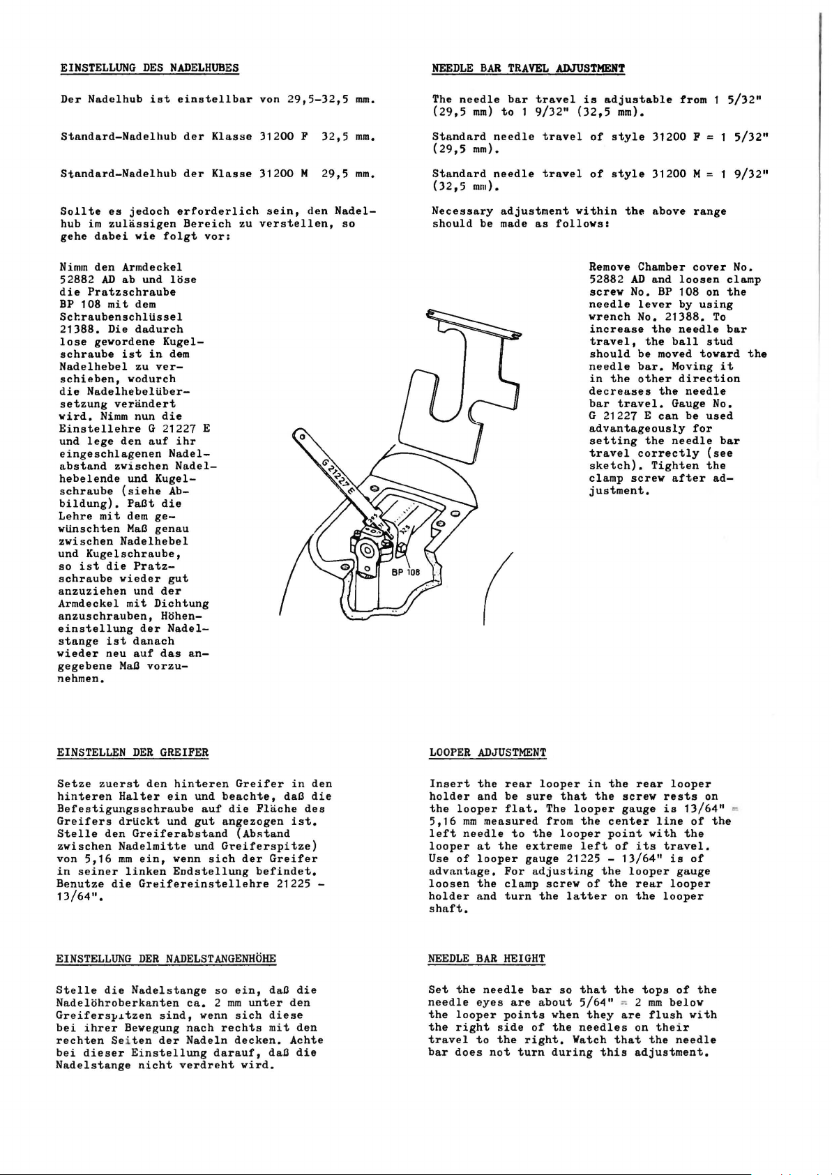
Nimm
52882
die
BP
Sccraubenschltissel
21388.
lose
schraube
Nadelhebel
schieben,
die
setzung
wird.
Einstellehre
und
eingeschlagenen
abstand
hebelende
schraube
bildung).
Lehre
wtinschten
zwischen
und
so
schraube
anzuziehen
Armdeckel
anzuschrauben,
einstellung
stange
wieder
gegebene
nehmen.
es
jedoch
im
zulassigen
dabei
wie
den
Armdeckel
AD
ab
mit
dem
Die
dadurch
ist
zu
wodurch
verandert
Nimm
nun
den
zwischen
und
(siehe
PaCt
mit
dem
MaC
Nadelhebel
die
Pratz-
wieder
und
mit
ist
danach
neu
auf
MaC
und
in
G 21227 E
auf
gegenau
Dichtung
der
vorzu-
Pratzschraube
108
gewordene
Nadelhebeltiber-
lege
Kugelschraube,
ist
Kugel-
der
der
erforderlich
Bereich
folgt
lose
Kugel-
dem
ver-
die
ihr
Nadel-
Nadel-
Ab-
die
gut
der
Hohen-
Nadel-
das
an-
Klasse
Klasse
vor:
31200 F 32,5
31200 M 29,5
sein,
zu
verstellen,
den
mm.
mm.
Nadel-
so
Standard
(29,5
mm).
Standard
(32,5
mm).
Necessary
should
be made
needle
needle
adjustment
as
travel
travel
follows:
of
style
of
style
within
the
Remove Chamber
AD
52882
screw
needle
wrench
needle
decreases
G 21227 E
No.
lever
the
travel.
No.
the
be
bar.
other
the
correctly
screw
increase
travel,
should
in
bar
advantageously
setting
travel
sketch).
clamp
justment.
31200 F
31200
above
and
loosen
BP
108 on
by
21388.
the
needle
ball
moved
Moving
direction
the
needle
Gauge No.
can
be
needle
Tighten
after
M = 1
range
cover
using
To
stud
toward
used
for
(see
the
ad-
5/32"
9/32"
No.
clamp
the
bar
the
it
bar
EINSTELLEN
Setze
hinteren
Befestigungsschraube
Greifers
Stelle
zwischen
von
5,16
in
seiner
Benutze
13/64".
EINSTELLUNG
Stelle
Nadelohroberkanten
Greifers~~tzen
bei
ihrer
rechten
bei
dieser Einstellung
Nadelstange
DER
zuerst
den
Halter
drtickt
den
Greiferabstand
Nadelmitte
mm
ein,
linken
die
Greifereinstellehre
DER
die
Nadelstange
Bewegung
Sei
ten
nicht
GREIFER
ein
und
NADELSTANGENHOHE
sind,
der
hinteren
und
beachte,
auf
die
gut
angezogen
und
wenn
Endstellung
verdreht
G~eiferspitze)
sich
so
ca. 2 mm
wenn
nach
rechts
Nadeln
darauf,
Greifer
Flache
(Abstand
der
Greifer
befindet.
ein,
daB
unter
sich
diese
mit
decken.
daB
wird.
in
daB
des
ist.
21225 -
die
den
den
Achte
die
den
die
LOOPER
Insert
holder
the
5,16
left
looper
Use
advantage.
loosen
holder
shaft.
NEEDLE
Set
needle
the
the
travel
bar
ADJUSTMENT
the
and
looper
mm
needle
at
of
looper
the
and
BAR
the
eyes
looper
right
to
does
rear
be
sure
flat.
measured
to
the
extreme
gauge
For
clamp
turn
HEIGHT
needle
are
points
side
the
right.
not
turn
looper
that
The
looper
from
the
looper
21225 -
adjusting
screw
the
latter
bar
so
about
when
of
the
Watch
during
in
the
the
the
center
point
left
the
of
the
that
5/64"
they
needles
this
rear
screw
gauge
with
of
its
13/64"
looper
rear
on
the
the
tops
"' 2 mm
are
flush with
on
that
the
adjustment.
looper
rests
is
line
travel.
is
looper
looper
of
below
the
i r
needle
13/64"
of
the
of
gauge
the
on
the
Page 6
GREIFERAUSWEICHBEWEGUNG
Nach
Einstellung
stelle
Venn
soll
der
sie
stiirke).
Bei
links,
rUckseite
vorbeigehen,
Nach
bewegung
Nadel
Nach
setze
beider
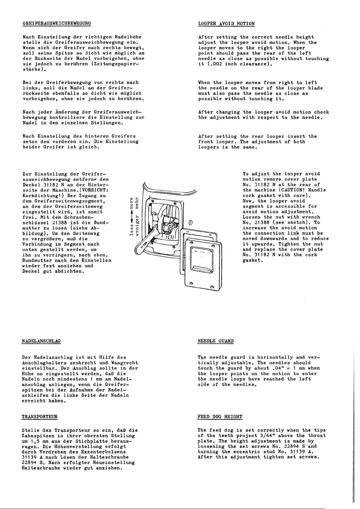
Zur
ausweichbevegung
Deckel
seite
Korkdichtung!)
dem
an
eingestellt
frei.
schlUssel
mutter
bildung).
zu
Verbindung
unten
ihn
Bundmutter
wieder
Deckel
die
sich
der
seine
RUckseite
jedoch
der
Greiferbewegung
soll
ebenfalls
jeder
kontrolliere
in
den
Einstellung
den
vorderen
Greifer
Einstellung
31182
der
Haschine.(VORSICHT:
Greiferse1tenvegsegment,
dem
der
Greiferseitenweg
Hit
dem
21388
zu
losen
gestellt
zu
verringern,
fest
gut
Um
nach
abdichten.
vergroBern,
der
so
Nadel
Nadel
sie
des
ein.
ist
gleich.
der
entfernP
der
Der
Zugang
ist
ist
(siehe
Seitenveg
muB
die
nach
dem
richtigcn
nach
jicht
(Zeitungspapier-
an
so
dicht
jedoch
der
die
Stellungen.
hinteren
Greifer-
Hinter-
somit
die
Ab-
nach
um
Einstellen
und
Greiferausveichbevegung
Greifcr
Spitze
der
zu
berUhren
die
ohne
Anderung
einzelnen
Nan
vird,
Schrauben-
den
im
Segment
werden,
anziehen
Nadelhohe
moglich
moglich
zu
berUhren.
Greifers
ein.
bevegt,
nach
rechts
wie
vorbeigehen,
von
rechts
der
Greifer-
wie
Greiferausweich-
Einstellung
Die
Einstellung
den
zu
Bund-
oben.
an
ohne
zur
...
"'
1-<..C:::
0 ...
E E
t
~
LOOPER
After
adjust
looper
point
needle
it
When
the
must
possible
After
the
After
front
loopers
AVOID
setting
the
moves
should
as
(.002
inch
the
looper
needle
also
without
changing
adjustment
setting
looper.
is
.
'
looper
close
on
pass
the
""Cj
'
MOTION
the
correct
avoid
to
the
pass
right
the
as
possible
clearance).
moves
the
rear
the
needle
touching
the
looper
with
respect
the
rear
The
adjustment
same.
To
adjust
motion
No.
)1182
the
machine
cork
gasket
Now,
the
segment
avoid
motion
Loosen
No. 21388
increase
the
connection
moved
downwards
it
upwards.
and
replace
No. 31182 N
gasket.
needle
motion.
the
rear
from
of
the
as
it.
avoid
looper
the
remove
N
looper
is
accessible
the
nut
(see
the
height
When
looper
of
the
without
right
to
looper
close
motion
to
the
insert
of
both
looper
cover
at
the
(CAUTION!
with
care).
avoid
adjustment.
with
sketch).
avoid
link
and
Tighten
the
cover
with
the
the
left
touching
left
blade
as
needle.
the
avoid
plate
rear
Handle
for
wrench
motion
must
to
reduce
the
plate
cork
check
of
To
be
nut
NADELANSCHLAG
Der
Nadelanschlag
Anschlaghalters
einstellbar.
Hohe
so
Nadeln
anschlag
spitzen
schleifen
erreicht
TRANSPORTEUR
Stelle
Zahnspitzen
um
1,5
ragen.
durch
Verdrehen
31139 A
22894
Halteschraube
S.
Der
eingestellt
noch
mindestens 1 mm
anliegen,
bei
der
die
haben.
den
Transporteur
in
mm
aus
Die
Hohenverstellung
nach
Losen
Nach
ist
senkrecht
Anschlag
venn
Aufnahme
linke
ihrer
der
Stichplatte
des
der
erfolgter
vieder
mit
Hilfe
und
Vaagrecht
werden,
Seite
Exzenterbolzens
sollte
daB
am
die
Greifer-
der
Nadel-
der
so
ein,
obersten
erfolgt
Halteschraube
Neueinstellung
gut
o.nziehen.
Nadel-
Nadeln
Stellung
heraus-
des
in
die
daB
der
die
NEEDLE
The
needle
tically
touch
the
the
looper
the
needle
side
of
FEED
DOG
The
feed
of
the
plate.
loosening
turning
After
this
GUARD
teeth
The
guard
adjustable.
guard
points
loops
the
needles.
HEIGHT
dog
is
project
height
the
the
set
eccentric
adjustment
is
horizontally
The
by
about
on
the
have
set
correctly
3/64"
adjustment
screws
needles
.04"
motion
reached
above
No. 22894 S
stud
No. 31139
tighten
= 1
the
when
is
set
and
should
mm
to
enter
left
the
the
made
screws.
verwhen
tips
throat
by
and
A.
Page 7
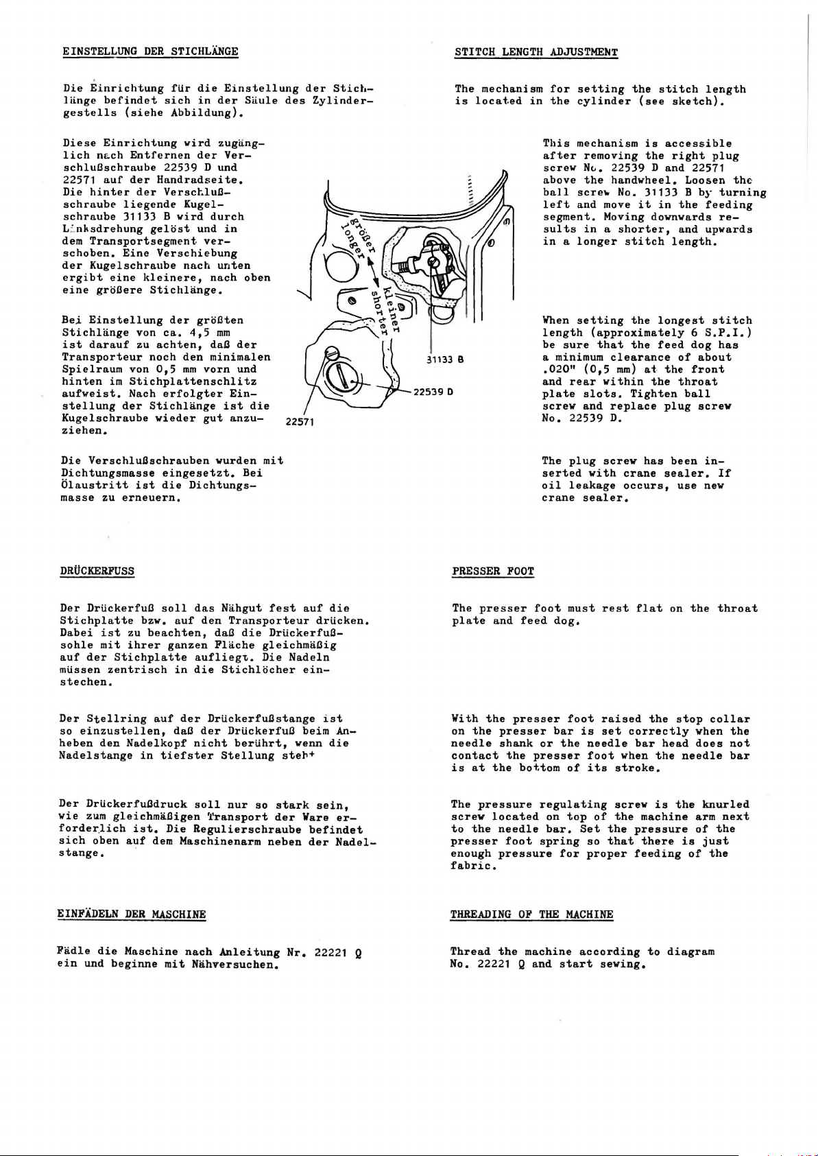
EINSTELLUNG
Die
Einrichtung
lange
gestells
Diese
lich
nLch
DER
befindet
(siehe
Einrichtung
Entfernen
schluBschraube
22571
auf
Die
schraube
schraube
L~nksdrehung
dem
schoben.
der
ergibt
eine
Bei
Einstellung
Stichlange
ist
der
hinter
der
liegende
31133 B
Transportsegment.
Eine
Kugelschraube
eine
kleinere,
gro3ere
von
darauf
zu
Transporteur
Spielraum
hinten
aufweist.
stellung
von
im
Stichplattenschlitz
Nach
der
Kugelschraube
ziehen.
STICHLANGE
fUr
die
sich
in
Abbildung).
wird
der
22539 D
Handradseite.
VersctluB-
Kugel-
wird
gelost
und
ver-
Verschiebung
nach
Stichlange.
der
groBten
ca.
4,5
achten,
noch
den
0,5
mm
vorn
erfolgter
Stichlange
wieder
gut
Einstellung
der
Saule
zugang-
Ver-
und
durch
in
unten
nach
oben
mm
daD
der
minimalen
und
Ein-
ist
die
anzu-
des
22571
der
Stict.-
Zylinder-
31133
22539 D
STITCH
The
mechanism
is
located
B
LENGTH
in
ADJUSTME~T
for
setting
the
cylinder
This
mechanism
after
screw
above
ball
left
segment.
sults
removing
N~.
the
sere"
and
move
Moving downwards
in a shorter,
in a longer
When
setting
length
be
(approximately
sure
that
a minimum
.020"
and
plate
screw
rear
slots.
and
(0,5
within
No. 22539
the
stitch
(see
is
accessible
the
22539 D
and
handwheel.
No. 31133 B
it
in
stitch
the
longest
the
feed
clearance
mm)
at
the
the
Tighten
replace
plug
D.
sketch).
right
22571
Loosen
by
the
and
upwards
length.
6
S.P.I.)
dog
of
about
front
throat
ball
screw
length
plug
th~
turning
feeding
re-
stitch
has
Die
Verschlu3schrauben
Dichtungsmasse
Olaustritt
masse
zu
erneuern.
ist
DRtiCKERFUSS
Der
Drtickerfua
Stichplatte
Dabei
sohle
auf
mtissen
ist
mit
der
zentrisch
zu
ihrer
Stichplatte
stechen.
Der
Stellring
so
einzustellen,
heben
den
Nadelkopf
Nadelstange
Der
Drtickerfu3druck
wie
zum
forder.lich
sich
gleichma3igen
ist.
oben
auf
stange.
eingesetzt.
die
soll
bzw.
auf
beachten,
ganzen
in
auf
daB
in
tiefster
Die
dem
wurden
Bei
Dichtungs-
das
Nahgut
den
Transporteur
daD
die
Flache
auflieg~.
die
Stichlocher
der
DrtickerfuBstange
der
DrUckerfua
nicht
bertihrt,
Stellung
soll
nur
~ransport
Regulierschraube
Maschinenarm
mit
fest
auf
Drtickerfu3gleichmaBig
Die
Nadeln
ein-
beim
wenn
steh+
so
stark
der
Ware
befindet
neben
der
die
drticken.
ist
An-
die
sein,
erNadel-
PRESSER
The
presser
plate
With
the
on
the
needle
contact
is
at
The
pressure
screw
to
the
presser
enough
fabric.
FOOT
and
feed
presser
presser
shank
the
the
bottom
located
needle
foot
pressure
The
plug
serted
oil
leakage
crane
foot
must
dog.
foot
bar
or
the
presser
of
regulating
on
top
bar.
spring
for
screw
with
sealer.
rest
raised
is
set
needle
foot
its
of
Set
so
proper
crane
occurs,
when
stroke.
screw
the
the
that
has
sealer.
flat
the
correctly
bar
head
the
is
machine
pressure
there
feeding
been
use
on
stop
needle
the
is
innew
the
when
does
knurled
arm
of
just
of
If
throat
collar
the
not
bar
next
the
the
EINFADELN
Fadle
ein
und
die
beginne
DER
MASCHINE
Maschine
mit
nach
Anleitung
Nahversuchen.
Nr.
22221 Q
THREADING
Thread
No. 22221 Q
the
OF
THE
machine
and
MACHINE
according
start
sewing.
to
diagram
Page 8
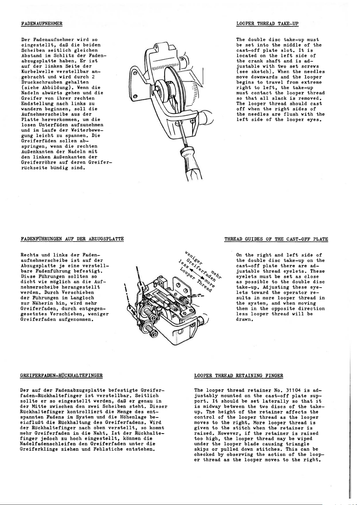
FADENAUFNEHMER
Der
Fadenaufnehmer
eingestellt,
Schejben
Abstand
abzugsplatte
auf
der
Kurbelwelle
gebracht
Druckschrauben
(siehe
Nadeln
Greifer
Endstellung
wandern
Aufnehmerscheibe
Platte
losen
und
gung
Greiferfaden
springen,
Auaenkanten
den
Greiferrohre
rtickseite
hervorkommen,
Unterfaden
im
Laufe
leicht
linken
daa
seitlich
im
Schlitz
haben.
linken
verstellbar
und
wird
Abbildung).
abwarts
von
ihrer
nach
beginnen,
der
zu
sollen
wenn
der
Auaenkanten
auf
btindig
wird
die
heiden
gleichen
der
Er
Seite
der
durch
gehalten
Wenn
gehen
und
rechten
links
soll
aus
der
urn
aufzunehmen
Weiterbewe-
spannen.
ab-
die
rechten
Nadeln
deren
sind.
so
Fadenist
an2
die
die
zu
die
die
Die
mit
der
Greifer-
LOOPER
The
be
cast-off
located
the
justable
(see
move downwards
begins
right
must
so
The
off
the
left
double
set
crank
sketch).
to
contact
that
looper
when
needles
side
THREAD
disc
into
the
plate
on
the
shaft
with
to
travel
left,
all
slack
thread
the
are
of
TAKE-UP
take-up
middle
slot.
left
and
two
When
and
from
the
the
looper
right
flush
the
looper
It
side
is
set
screws
the
the
extreme
take-up
is
removed.
should
sides
with
must
of
the
is
of
adneedles
looper
thread
cast
of
the
eyes.
FADENFUHRUNGEN
Rechts
aufnehmerscheibe
Abzugsplatte
bare
Dibse
dicht
nehmerscheibe
werden.
der
zur
Greiferfaden,
gesetztes
Greiferfaden
GREIFERFADEN-RUCKHALTEPINGER
Der
faden-Rtickhaltefinger
sollte
der
Rtickhaltefinger
spannten
eiufluBt
der
mehr
finger
Nadelfadenschleifen
Greiferklinge
und
Fadenftihrung
Ftihrungen
wie
Durch
Ptihrungen
Naherin
auf
der
er
Mitte
Fadens
die
RUckhaltefinger
Greiferfaden
jedoch
AUF
DER
links
der
Faden-
ist
je
moglich
herangestellt
Verschieben
im
hin,
durch
Verschieben,
aufgenommen.
Fadenabzugsplatte
so
eingestellt
zwischen
Rtickhaltung
zu
ziehen
auf
eine
verstell-
befestigt.
sollten
an
die
Langloch
wird
entgegen-
den
kontrolliert
im
System
nach
in
die
hoch
eingestellt,
den
und
ABZUGSPLATTE
der
so
Auf-
mehr
weniger
ist
verstellbar.
werden,
zwei
Scheiben
und
des
oben
Naht.
Greiferfaden
Fehlstiche
befestigte
die
die
Greiferfadens.
verstellt,
Ist
Seitlich
daB
er
steht.
Menge
des
Hohenlage
der
Rtickhalte-
konnen
unter
entstehen.
Greifer-
genau
Dieser
ent-
beWird
so
kommt
die
die
in
LOOPER
The
looper
justably
port.
is
midway
up.
The
control
moves
given
raised.
too
high,
under
skips
checked
er
thread
THREAD
THREAD
mounted
It
should
between
height
of
to
the
to
the
However,
the
the
looper
or
pulled
by
as
GUIDES
On
the
the
cast-off
justable
eyelets
as
possible
take-up.
lets
sults
the
them
less
drawn.
RETAINING
thread
on
be
of
the
looper
right.
stitch
if
looper
blade
down
observing
the
looper
right
double
plate
must
toward
ln
more
system,
in
the
looper
retainer
the
set
laterally
the
two
the
retainer
thread
More
when
the
thread
causing
stitches.
the
OF
THE
and
disc
there
thread
be
to
the
Adjusting
the
looper
and
opposite
thread
FINGER
No.
cast-off
discs
as
looper
the
retainer
retainer
may
action
moves
to
CAST-OFF
left
take-up
are
eyelets.
set
as
double
these
operator
thread
when
moving
direction
will
31104
plate
so
of
the
affects
the
thread
is
be
wiped
triangle
This
of
the
the
side
on
adThese
close
eye-
re-
be
is
sup-
that
takethe
looper
is
is
raised
can
be
loop-
right.
PLATE
of
the
disc
in
ad-
it
Page 9
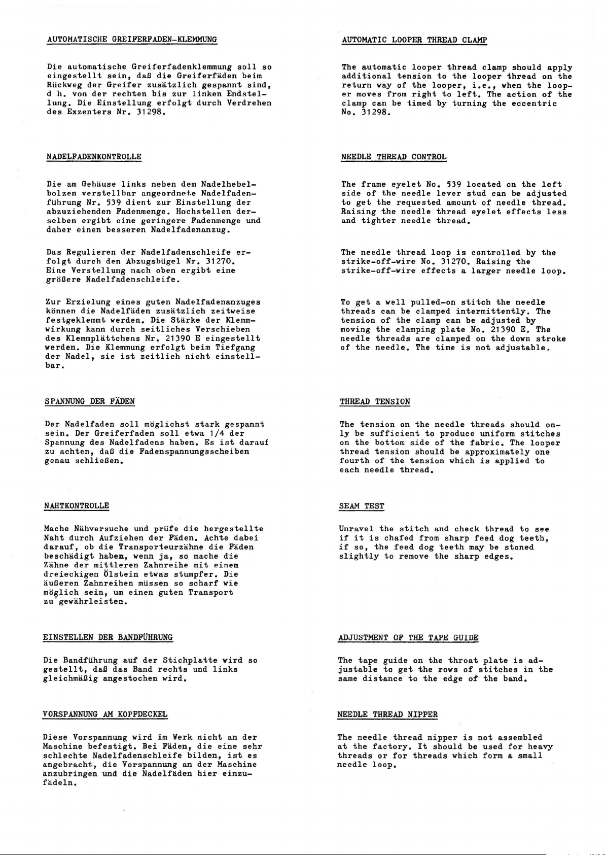
AUTOMATISCHE
Die
automatische
eingestellt
Rtickweg
d
h.
lung.
des
der
von
der
Die
Einstellung
Exzenters
Greifer
GREIFERFADEN-KLEMMUNG
Greiferfadenklemmung
sein,
daB
die
Greiferfaden
rechten
Nr.
zusatzlich
his
erfolgt
31298.
zur
gespannt
linken
durch
soll
beim
sind,
Endstel-
Verdrehen
so
AUTOMATIC
The
automatic
additional
return
er
clamp
No.
way
moves from
can
31298.
LOOPER
looper
tension
of
the
right
be
timed
THREAD
thread
to
the
looper,
to
by
turning
CLAMP
looper
i.e.,
left.
clamp
The
the
should
thread
when
action
eccentric
the
apply
on
loop-
of
the
the
NADELFADENKONTROLLE
Die
am
bolzen
ftihrung
abzuziehenden
selben
daher
Das
folgt
Eine
grHBere
Zur
ktinnen
festgeklemmt
wirkung
des
verden.
der
bar.
SPANNUNG
Der
sein.
Spannung
zu
genau
Gehuuse
verstellbar
Nr.
ergibt
einen
Regulieren
durch
Verstellung
Nadelfadenschleife.
Erzielung
die
kann
Klemmplattchens
Die
Nadel,
Nadelfaden
Der
des
achten,
schlieBen.
links
539
dient
Fadenmenge.
eine
besseren
der
den
Abzugsbtigel
nach
eines
Nadelfaden
verden.
durch
Klemmung
sie
ist
DER
FADEN
soll
Greiferfaden
Nadelfadens
dna
die
nngeordnP.te
geringere
Nadelfadenschleife
seitliches
zeitlich
Fadenspannungsscheiben
neben
dem
Nadelhebel-
zur
Nadelfadenanzug.
oben
guten
zusatzlich
Die
Starke
Nr.
21390 E eingestellt
erfolgt
mtiglichst
soll
haben.
NadelfadenEinstellung
Hochstellen
Fadenmenge
Nr.
ergibt
Nadelfadenanzuges
Verschieben
beim
nicht
stark
etwa
Es
31270.
eine
zeitweise
der
Klemm-
Tiefgang
einstell-
gespannt
1/4
der
ist
der
der-
und
er-
darauf
NEEDLE
The
side
to
Raising
and
The
strike-off-wire
strike-off-wire
To
threads
tension
moving
needle
of
THREAD
The
ly
on
thread
fourth
each
THREAD
frame
of
the
get
the
the
tighter
needle
get a well
can
of
the
threads
the
needle.
TENSION
tension
be
sufficient
the
bottom
tension
of
the
needle
CONTROL
eyelet
needle
requested
needle
needle
thread
pulled-on
be
clamped
the
clamp
clamping
are
The
on
the
side
should
tension
thread.
No. 539
lever
thread
thread.
loop
No.
31270.
effects
can
plate
clamped
time
needle
to
produce
of
located
stud
amount
the
be
which
of
eyelet
is
controlled
Raising
a
larger
stitch
intermittently.
be
adjusted
No. 21390
on
is
not
threads
uniform
fabric.
approximately
is
on
the
can
be
needle
effects
the
needle
the
needle
E.
the
down
adjustable.
should
stitches
The
applied
left
adjusted
thread.
less
by
the
loop.
The
by
The
stroke
on-
looper
one
to
NAHTKONTROLLE
Mache
Nahversuche
Naht
durch
darauf,
beschadigt
Zahne
dreieckigen
auBeren
mtiglich
zu"gewahrleisten.
EINSTELLEN
Die
Bandftihrung
gestellt,
gleichmaBig
VORSPANNUNG
Diese
Maschine
schlechte
angebracht.,
anzubringen
fadeln.
Aufziehen
ob
die
haben,
der
mittleren
Olstein
Zahnreihen
sein,
DER
daB
angestochen
AM
Vorspannung
befestigt.
Nadelfadenschleife
die
und
und
prtife
der
Transporteurzahne
wenn
urn
einen
BANDFUHRUNG
auf
das
Band
KOPFDECKEL
wird
Vorspannung
die
Faden.
ja,
Zahnreihe
etwas
mtissen
der
Bei
Nadelfaden
so
guten
Stichplatte
rechts
wird.
im Werk
Faden,
stumpfer.
die
Achte
so
mache
mit
scharf
Transport
und
nicht
die
bilden,
an
der
hier
hergestellte
dabei
die
Faden
die
einem
Die
wie
wird
links
an
der
eine
sehr
ist
Maschine
einzu-
so
es
SEAM
TEST
Unravel
if
if
slightly
ADJUSTMENT
The
justable
same
NEEDLE
The
at
threads
needle
it
so,
tape
distance
needle
the
the
is
chafed
the
to
guide
to
THREAD
factory.
or
loop.
stitch
feed
remove
OF
THE
get
to
NIPPER
thread
for
and
from
dog
the
TAPE
on
the
the
the
nipper
It
should
threads
sharp
teeth
throat
rows
edge
check
may be
sharp
GUIDE
of
of
is
be
which
thread
feed
dog
stoned
edges.
plate
stitches
not
used
is
the
band.
assembled
for
form a small
to
see
teeth,
ad-
in
heavy
the
Page 10
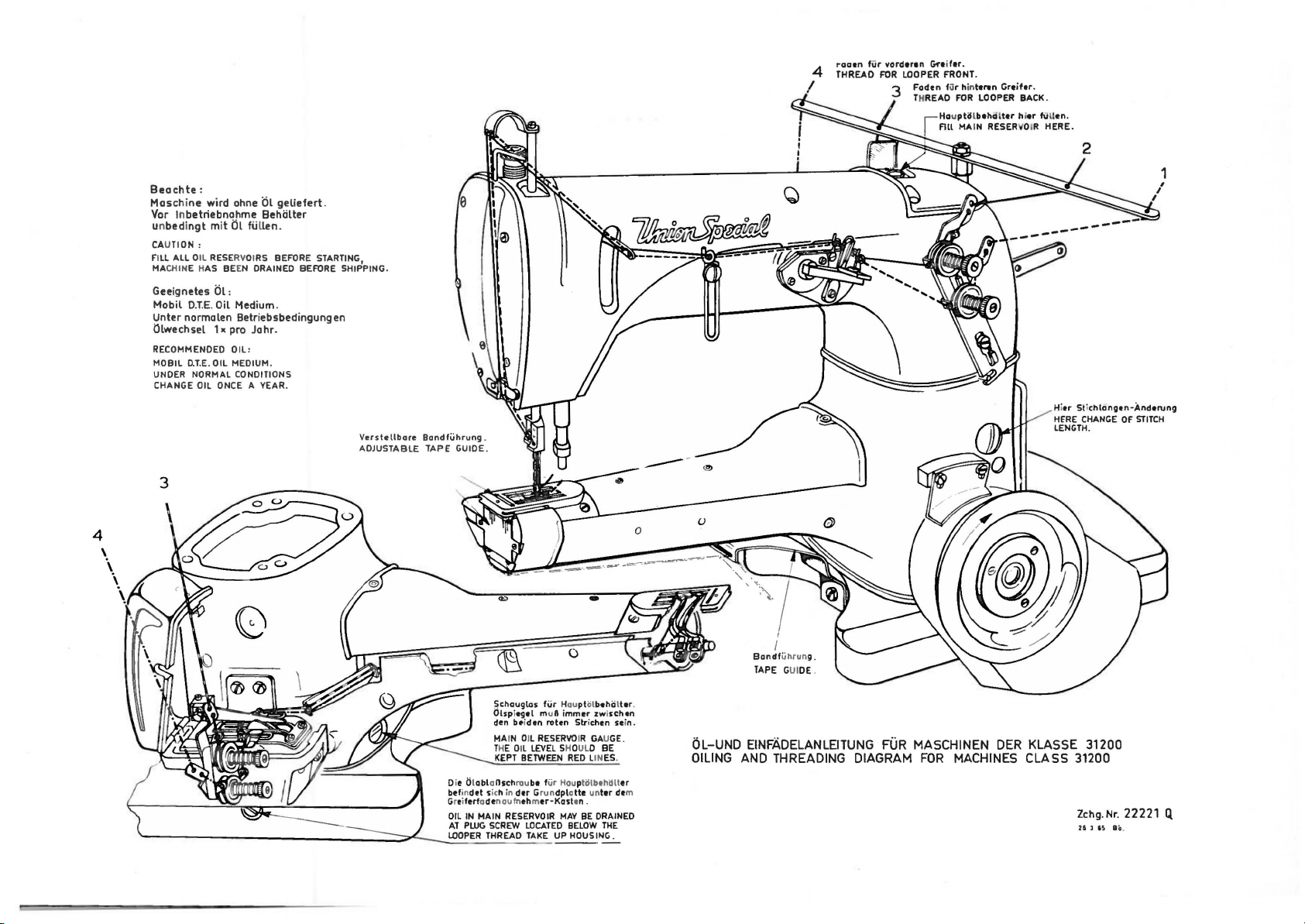
raaen
fUr
vorderen
Gre
4
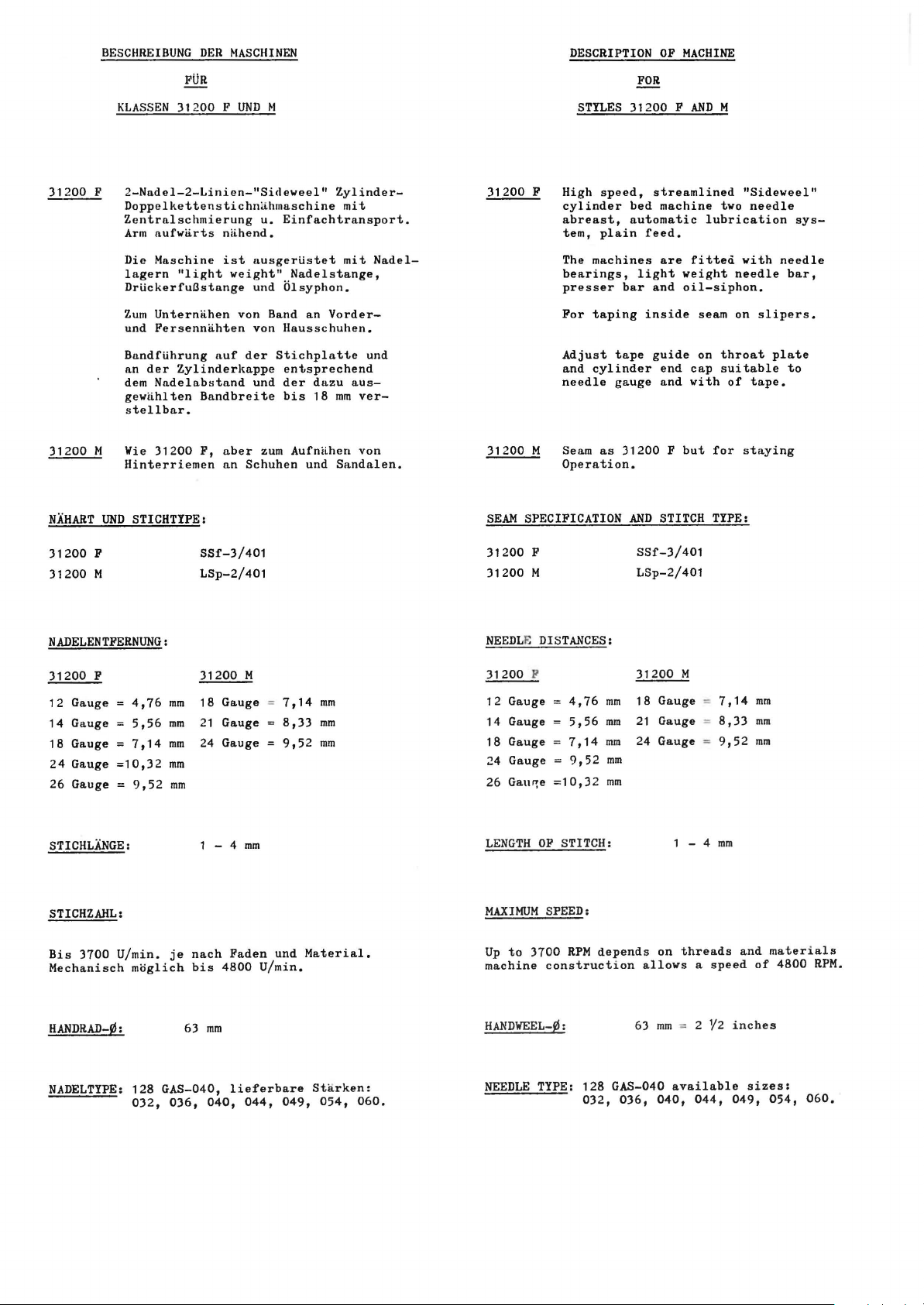
THREAD
FOR
I
ifer.
LOOPER FRONT.
Faden
fur hinttren
THREAD
FOR
Grtifor.
LOOPER BACK.
4
Beachte:
Maschine
Var ln
un
CA
f i
ll
MACHINE HAS
Geeignetes
Mobil
Unter norma len
illwechsel
RECOMMENDED
MOBIL
UNDER NORMAL CONDITIONS
CHANGE OIL ONCE A YEAR.
wird ohne
betriebnahme
bedingt
mit
UTION :
ALL OIL RESERVOI
BE
Ol:
O.T.E.
Oil Medium.
1 x pro
O.T.E
. OIL MEDIUM.
Ol
Behiilter
til
fiillen.
RS
BEFORE STARTING,
EN DRAINED BEFORE SHIPPING.
Betriebsbedingungen
Johr.
Oil:
3
geliefert.
Verstollbore
ADJUSTABLE
Bondfuhrung.
TAPE
GUIDE .
...,
-
Hi
tr
St
ichlangen-Anderung
HfRE
CHANGE
LENGTH.
OF
1
STITCH
schouglos
Olspi
den b•iden rot
MAIN OIL
THE
KEPT
Die OlobloOschrou
befindet sich
Greiferf odenoufnehm
OIL
IN
MAIN
AT
PWG
SCREW
LOOPER
THREAD
fiir Houplol
egel
mu8 immer zwi
RESERVO
Oil
LEVEL
BETWEEN
bt
fiir
in
dtr
Grundplatte unter
er-Kasten.
RESERVOIR
LOCATED
TAKE
en
SHOULD BE
Hou
MAY
UP HDVSINC..
0
Stri
ehen sei
IR GAUGE.
RED
LINES.
pti!lbthi!lt
BE
BELOW
bthiiltor
schen
er
dt
DRAINED
THE
I
Bondf
iihrun
GUIDE.
g.
FUR
MASCHINEN
FOR
DER
MACHINES
KLASSE 31200
CLASS 31200
Zchg.
Nr.
21 ] u
22221
80
Q.
TAPE
.
n.
OL-UND EINFADELANLEITUNG
OILING
m
AND THREADING DIAGRAM
Page 11
,r ·-...._
-"""""
-
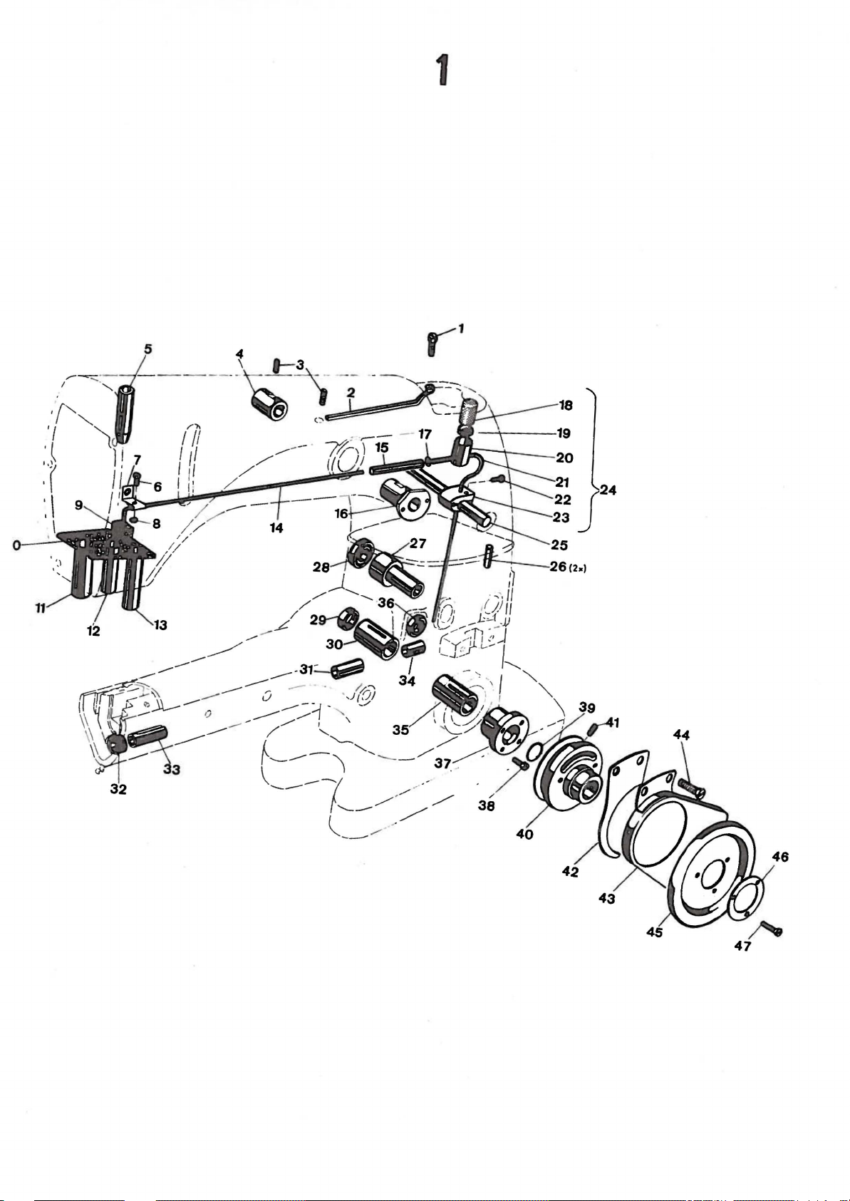
1
18
Page 12
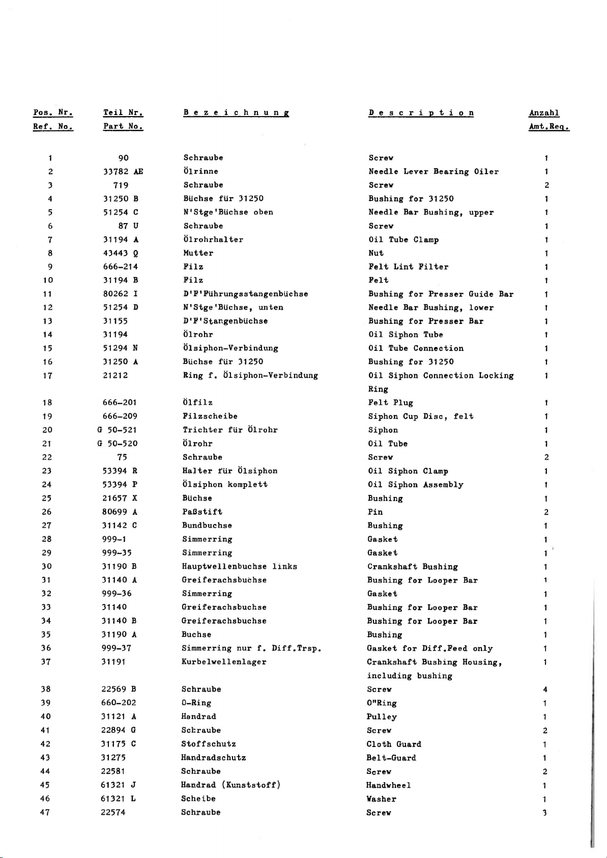
Pos.
Ref.
Nr.
No.
Teil
Part
Nr.
No.
B e z e i c h n u n g
D e s c r i p t i o n
Anzahl
Amt.Reg.
10
11
12
13
14
15
16
17
18
19
20
21
22
23
24
25
26
27
28
29
30
31
32
33
34
35
36
37
38
39
40
41
42
43
44
45
46
47
90
33782
2
3
4
5
6
7
8
9
AE
719
31250 B
51254 c
87 u
31194 A
43443 Q
666-214
31194 B
80262 I
51254 D
31155
31194
51294
N
31250 A
21212
666-201
666-209
G 50-521
G
50-520
75
53394 R
53394 p
21657 X
80699 A
31142 c
999-1
999-35
31190 B
31140
A
999-36
31140
31140
B
31190
A
999-37
31191
22569 B
660-202
31121 A
22894 G
31175 c
31275
22581
61321
J
61321 L
22574
Schraube
(ilrinne
Schraube
BUchse
N'Stge'BUchse
Schraube
Olrohrhalter
Mutter
Filz
Filz
D'F'FtihrungsstangenbUchse
N'Stge'BUchse,
D'F'StangenbUchse
Olrohr
Olsiphon-Verbindung
BUchse
Ring
Olfilz
Filzscheibe
Trichter
Olrohr
Schraube
Halter
Olsiphon
BUchse
Pal3stift
Bundbuchse
Simmerring
Simmerring
Hauptwellenbuchse
Greiferachsbuchse
Simmerring
Greiferachsbuchse
Greiferachsbuchse
Buchse
Simmerring
Kurbelwellenlager
Schraube
D-Ring
Handrad
Scl::raube
Stoffschutz
Handradschutz
Schraube
Han.drad
Schei.be
Schraube
fUr
31250
oben
unten
fUr
31250
f.
Olsiphon-Verbindung
fUr
Olrohr
fUr
Olsiphon
komplett
links
nur
f.
Diff.Trsp.
(Kunststoff)
Screw
Needle
Screw
Bushing
Needle
Screw
Oil
Nut
Felt
Felt
Bushing
Needle
Bushing
Oil
Oil
Bushing
Oil
Ring
Felt
Siphon
Siphon
Oil
Screw
Oil
Oil
Bushing
Pin
Bushing
Ga.sket
Gasket
Crankshaft
Bushing
Gasket
Bushing
Bushing
Bushing
Gasket
Crankshaft
including
Screw
O"Ring
Pulley
Screw
Cloth
Belt-Guard
Screw
Handwheel
Washer
Screw
Lever
Bar
Tube Clamp
Lint
Bar
Siphon
Tube
Siphon
Plug
Cup
Tube
Siphon
Siphon
for
Guard
Bearing
for
31250
Bushing,
Filter
for
Presser
Bushing,
for
Presser
Tube
Connection
for
31250
Connection
Disc,
Clamp
Assembly
Bushing
for
Looper
for
Looper
for
Looper
Diff.Feed
Bushing
bushing
Oiler
upper
Guide
lower
Bar
felt
Bar
Bar
Bar
only
Housing,
2
Bar
Locking
2
2
4
2
1
2
1
'3
Page 13

2
76
/
~
84
J:
~Zl
97
87
9695Js
94
~
48
Page 14

Pos.
Ref.
Nr.
No.
Teil
Part
Nr.
No.
B e z e i c h n u n g
D e s c r i p t i o n
Anzahl
Amt.Req.
10
11
12
13
14
1 5
16
17
18
19
20
21
22
23
24
25
26
27
28
29
30
31
32
33
34
35
36
37
38
39
40
41
42
43
44
45
46
47
48
49
50
51
52
53
53
A
31191
2
3
22839 c
22539 D
Dichtung
Schro.ube
VerschluUschro.ube
f.
Stich-
Gasket.
Screw
Plug
Screw
4
1
verstellung
4
5
6
7
8
9
33782 E
31182 N
99274
33782
B
33782 y
90
52882 p
31282 B
22541 B
52882
AD
39582 L
52882
AC
50-789
52882
AA
90
31158 B
95
22768
31158
A
31282 A
31270
95
31282
22569
605 A
57
WD
57
we
G 57
WB
43296
31117
51458
22768
22889
A
539
20
22848
99287
99287
B
31182
99287
c
999-41
31279
F
12179 D
22561
12179
c
31279 M
31182 R
31182
B
312'l8 D
376
A
a.
31258
DA
Dichtung
Deckel
Schro.ube
Dichtung
Olspritzblech
Schro.ube
Dichtung
Schra.ube
Schra.ube
Armdeckel
kompl.
Klo.ppdeckel
Feder
Stift
Olfa.ngblech
Schra.ube
Fa.denleitbtigel
Schra.ube
Schro.ube
Fa.denftihrung
a.uf
N'Sto.nge
Kopfdeckeldichtung
Fa.dena.bzugsha.ken
Schraube
Kopfdeckel
Schra.ube
Schra.ube
Ansa.tzschra.ube
Fa.denspa.nnungsfeder
Fa.denspa.nnungsplattchen
Fa.denspa.nnungsha.lterplattchen
Na.delsta.nge
Fa.denftihrung
siehe
a.m
Na.delhebel
Seite
7
Schra.ube
Schra.ube
Fa.denftihrung
Scheibe
Schra.nbe
Schra.ube
Schra.ube
Zylinderdeckel
Schra.ube
Gummischnur
f.
31182
Zylinder-Endka.ppe
Plattchen
fUr
Ba.ndftihrung
Schra.ube
Bandftihrungsleisten
Zylinder-Endka.ppe
komplett
Dichtung
Ha.ltebtigel,
Fa.denftihrung,
vorn
hinten
Schra.ube
Scheibe
Gasket
Cover
Screw
Gasket
Baffle
Plate
Screw
Gasket
Screw
Screw
Chamber
Oil
Oil
Oil
Drip
Ca.p
Ca.p
Ca.p
Plate
Cover
Torsion
Hinge
Screw
Needle
Thread
Screw
Screw
Needle
Bar
Gasket
Pull-off
Wire
Screw
Head
Cover
Screw
Screw
Nipper
Nipper
Nipper
Needle
Needle
Needle
Spring
Spring
Spring
Thread
Bar
Lever
Screw
Screw
Thread
Eyelet
Washer
Screw
Screw
Screw
Cylinder
Cover
Screw
Rubber-string
Cylinder
Plate
for
End
Tape
Screw
Bader
for
Tape
Cylinder
End
Gasket
Support
Thread
for
Eyelet,
Screw
Washer
Spring
Pin
leading
Thread
Screw
Plate
Nipper
Thread
Cover
Guide
Guide
Cover
Cylinder
rear
Wire
Eyelet
Bore
Eyelet
complete
Cover,
front
4
2
1
2
2
1
1
1
5
2
2
2
1
2
1
Page 15

26
3
13
z;:t-
~05
~
27cs.)
Page 16

Po~
Ref.
No.
Teil
Part
Nr.
No.
Bezeichnu.!!....&
D e s c r i p t i o n
An~
Amt.Req.
54
55
56
57
58
59
60
61
62
63
64
65
66
67
68
69
70
71
72
73
74
75
76
77
78
79
80
81
82
83
84
85
86
87
88
89
90
91
92
93
94
95
96
97
98
99
100
101
102
103
104
105
106
107
108
G
G
M
129
31182
31182
31182
22766
31182
31258
77
31263
77L
99242
22733
50-434
41394
33782
22585
90939
31138
11638
HA
86
999-32
99292
31258
96201
11638
22571
31203
25
31251
22704
52
21390
58
22585
51225
75255
31250
87
31251
22729
21390
22747
43443
41358
)1279
31279
96852
31279
99275
22804
52882
)12)5
88
31203
90561
C
T
s
K
c
c
K
B
A
c
A
H
M
B
M
s
A
A
A
w
A
u
A
A
E
B
Q
c
A
B
V
D
A
B
Niet
Hnlteblech
Spri
tzlappen
Olspritzblcch
Schraube
HnJtebUgcl,
FadenfUhrung,
hinten
vorn
Schraube
Rnstfedcr
Schrnube
Schrnube
fUr KlK
fUr
Klnsse
fur
)1182
i:ilnblnl.lschrnube
i:hstnndsnugc
Dichtungs
ring
Dichtung
Schrnube
Schrnube
Stift
fUr
Zugfeder
Hutter
Federscheibe
Dichtring
Schrnube
Fadenosenhnlter
Federring
Hutter
VerschluOschrnube
BandfUhrung
Schrnube
Grundplntte
Schrnube
~'ndenfUhrung
Fadenklemmfeder
Fadenklemmfeder
Schraube
Scheibe
Mutter
BUchse
fUr
31250
Schraube
Fndenl1lemmhebel
Schraube
FederdrUcker
Scr.raube
Mutter
Unterlegscheibe
Zylinder-Endknppe
Kappenhalter
Kerbstift
Raste
Schraube
Scl:rnube
Anschln.gschraube
Halter
Schrn.ube
BandfUhrung
Holzschraube
sse
)1200
)1200
B
Rivet
2
Holding-plate
Splash-leather
Baffle
Screv
Support
Thread
Plate
for
Eyelet,
Cylinder
front
Cover,
1
2
rear
Screv
F
F
Ln.tch
Screv
Screv
Oil
Lucite
Spring
for
for
Drain
Oil
for
Class
31182
Screv
Gauge
Class
)1200
B
)1200
F
F
2
Gasket
Gasket
Screv
Screv
2
4
Spring-pin
Nut
Spring
Washer
Gasket
Screv
Eyelet-Support
Locking
Ring
Nut
Plug
Screv
Tape
Guide
Screv
Base
Plate
Screv
Thread
Needle
Nipper
Needle
Nipper
Screv
Eyelet
Thread
Spring
Thread
Spring
2
Intermittent
Intermittent
2
Wn.sher
Nut
Bushing
for
31250
Screw
Thread
Nipper
Lever
Screw
Spring
Latch
Screw
Nut
Washer
Cylinder-End
Cover
Holder
Cover
Pin
Bolt
for
Cylinder
End
Cover
Screw
Screw
Screw
Holder
Screw
Tape
Guide
Wood
Screw
Page 17

4
y-a
~9
10
3
~'
I
I
I
I
I
I
I
I
I
2
19
4
t26
I
I
8-20
~
$
~
v
22
Page 18

Pos.
Nr.
Ref . No.
Tcil
Part
Nr.
No.
B c z e
i c h n u n
g
D e s c r
i
t i o n
I!
~
Amt.Rcq.
BP
108
2
3
4
5
6
7
8 22768
9
10
11
12 22768
13
14 31116 G
15
16
17 31156
18
19
20
21
22
23
24 G
25
26
27
28 51054
29
30
31
32
531
12935
31250 B
31250 A
660-207
31250
31158
31117
51458
G 29476
15430
52816 G
97
G
29066 B
99290
31116
75
HA
61
29348
78
77
54
666-149
51
254 H
22562
31215
A
A
w
c
A
A
A
D
F
A
Schraube
Schraube
Gewindestift
BUchse
BUchse
Olnbstreifring
Nadelhet:elbolzen
Schraube
FndenfUhrung
Nadelstange
FadenfUhrung
Schraube
Nadelhebelverb
Nadelhebelverbindung
Hutter
Lagerschale
Kugelbolzen
Schraube
Kugellager
Hutter
Lagerschale
Schraube
Schraube
Nadelhebel
Schraube
Schraube
Verbindungsgelenk
Konischer
Docht
Hitnehmer
Schraube
Nadelhebel
fUr 31250
fUr 31250
auf
am
i ndung
links
komplett
komplett
Stift
Nadelhebel
Nadelstange
komplett
Screw
Screw
Screw
Bushing
Bushing
Oil
Needle
Screw
Needle
Needle
Needle
Screw
Needle
Needle
Nut
Needle
Ball
Screw
Needle
Nut
Needle
Screw
Screw
Needle
Screw
Screw
Needle
Link
Lubricating
Needle
Screw
Needle
for
for
Seal
Lever
Bar
Bar
Lever
Lever
Lever
left
Lever
Lever
Lever
Lever
Bar
Pin
Bar
Lever
31250
31250
Ring
Stud
Thread
Thread
Rod
Rod
Threo.d
Ball
Ball
Ball
Assembly
Link
Felt
Connection
Eyelet
Eyelet
Assembly
Joint
Joint
Joint
2
2
Bearing
2
Bearing
2
2
2
2
Page 19

cf~
I
~:.: '
.~~;F--·~
,
...
,
44
,/
I /
: ':•#'
..
~..:
,;t,~/
:
::.~:
,'
:;::
~:
l :
1'
,,
I : 1 \1
I
,
,~'
'I
I
~~~
tJ
,'
,~,
..
..
,
I
~~~
••
1
, ,,
..
,
j.~·.::~,--
,•
:n
...
e
53
•
19
~Z~~o
23
)/:> .\.
<.___
'·
.
~21
(J1
Page 20

Pus.
Nr.
R<'l'. No.
Teil
Part
Nr.
No.
B e z e
c h n u n g
D e s c r i p t
o n
~
Amt.Req.
10
11
12
13
14
15
16
17
18
19
20
21
22
23
24
25
26
27
28
29
30
31
)2
33
34
35
36
37
38
39
40
41
42
43
31139
31146
G
29476
G
29476
31139
357·
2289•1 c
31106
258
97 A
16
28 B
X
S
B
c
A
2
3
4
5
6
7
ll
')
22559 c
31
1<12
A
'}99-1
Jt.142
B
22517
31242
125)8
)1144
c
31144 B
)1144
E
77
B
97 A
)1144
D
G 97 A
18
31244
Trnn:;porthuhhebel
~Iutter
Scheibe
Doppe I
Lager
fiir
kompl.
Dopp<'Linger
lwmpl.
fUr
fUr
Klnsse
fUr
Klnsse
Schrnube
Lnge
rschnl
e
Kugelschrnube
Schruube
Schrnube
Exzer.ter
Schrnube
Bundnchse
Simmer
ring
Bolzen
Schraube
Doppelhebel
Mutter
Kugelschraube
Lagerschale
FUhrungsgnbel
Schrnube
Schrnube
Kugelschrnube
Schrnube
Nutter
Antrietsgelenk
Trnnsporthub
)1200
Trnnsporthub
)1 2
00
lwmpl.
F
M
Feed
Rocker
Nut
Washer
Feed
Lift
for
Style
Feed
Lift
for
Style
Screw
Bearing
Ball
Screw
Screw
Screw
Eccentric
Screw
Bar
for
Gasket
Link
Pin
Screw
Looper
Nut
Ball
Screw
Bearing
Guide
Fork
Screw
Screw
Ball
Screw
Screw
Nut
Looper
Connection
31200
Connection
31200
Looper
Drive
Drive
Arm
Lever
Lever
F
M
Avoid
Assembly
Assembly
Lever
and
Link
2
1
2
2
1
3
Assembly
)1144
G
22517
227))
15037
31248
22562 A
22564 D
)1207
31207
M
31209
31209
M
)1244
A
)1116
G
99290
31116
A
75 A
999-39
)1222
75 A
A
R
Greiferantriebsh!'bel
Schr••ube
Schrnube
Nutter
Greiferhnlter,
vorn
Schrnube
Schraube
Greifer
Greifer
Greifer
Greifer
vorn
vorn
hinten
hinten
fUr
fUr
f.Klasse
f.Klasse
Greiferachse
Nadelhebelverbindung
Mutter
Lagerschnle
Schraube
Nadelkiifig
f.
N'li'-Antriebslager
Kurbehrelle
Schraube
Klasse
Klnsse
)1200
31200
31200
)1200
F
M
F
M
Looper
Screw
Screw
Nut
Looper
Screw
Screw
Looper
Looper
Looper
Looper
Looper
Needle
Nut
Bearing
Screw
Needle
Crank
Screw
Drive
Holder,
front
front
rear
rear
Rock
Lever
Bearing
Shaft
Lever
for
for
for
for
Shaft
Rod
front
Class
Class
Class
Class
31200
31200
31200
31200
2
2
F
M
F
M
2
2
2
Page 21

r
••••
(t~·46
.,.~
' .4.'
:~:
~
\\\}:\
\\~·
44
~,
~
\
\\\
:
~t
:
;:
:.
I lo
Ill-·~
I II
.r
I,~'
••
,'Itt~/
I ,
I /
I ':"
.._;s
~:-----38
/
;r....l:
,,
::
,,
,
37
49
48
'
~
51
52
''""'0~
I '
/
"•
~
""
"lf~>
r
I
.,-.
'-......
5j
',"
60
61
62
~
.. .. ..
1 '-......"-. 78\
"
~
6
~
~
..
"'--
"
~
~·
j1
0-
'"'
~,{··
851¥
1.
~~~0
.~81
80
7~~
~
-~~1f
-~20
~liJ.
'--:·v21
7 L._
'--
-
30
--~~
-~2
36
11·~
'.J
:t
1
~
62~1
61
/
/
U~J
~P.~
68
67
I !/ .1
~
86
..
-~
7r-;
Page 22

Pos.
Ref.
Nr.
No.
Teil
Part
Nr.
No.
B e z c i c h n u n g
D e s c r i p t i o n
~
Amt.Reg.
44
45
46
47
48
49
50
51
52
53
54
55
56
57
58
59
60
61
62
6)
64
65
66
67
68
69
70
71
72
73
74
75
76
77
78
79
80
81
82
83
84
85
86
31116
999-)8
15430
31248
1196)
)113)
999-30
HA
482 A
88
31142
22894
31142
125)8
31116
12538
43242
G
4)242
31116
999-40
)1106
22894 c
22559 c
G 29476 N
31144
77
462
12538
12055 N
G
51054
666-149
)11J)
31116 D
18
31133 D
269
31133 A
521!41
c
31133 B
97
A
999-32
)1142
p
462
21657 E
F
c
A
c
N
s
M
D
N
p
A
Greiferantriebsverbindungsstange
Nodelkafig
f.Greifcrantriebslager
Mutter
Greiferhalter,
hinten
Kulissenbolzen
Stellmutter
0-Ring
Stell
ring
Schraube
Transport
u.
Greifer-Antriebs-
hebel
Schraube
Gelenkbolzen
Mutter
Verbindungsgelenk
Mutter
Gewindebolzen
Mutter
Lagerschale
Nadellager
f.
Transport
und
Greiferantriebsexzenter
Exzenter
Schraube
Scl:raube
Transportantriebsverbindung
Gelenk
Schraube
Mutter
Mutter
Gr.Hebelgelenk
Geler.kst1ft
Docht
Verbindungsstange
komp
l .
Gelenk
Mutter
Verbindungsstange
Hutter
Lagerschale
kompl.
Lagerschale
Kugelschraube
Schraube
0-Ring
Achse
f.
31142 N
Mutter
Scheibe
Looper
Needle
Drive
Bearing
Nut
Looper
Stud
Holder,
for
Adjusting
"0"-Ring
Collar
Screw
Feed
Drive
Drive
Lever
Screw
Link
Pin
Nut
Link
Nut
Connecting
Nut
left
Bearing
Needle
Bearin~t
Eccentric
Screw
Screw
Feed
Drive
Connection
Looper
Avoid
Screw
Nut
Nut
Looper
Link
Oil
Avoid
Pin
Wick
Connection
Link
Nut
Connection
Nut
Ball
Bearing
Ball
Bearing
Ball
Screw
"0"-Ring
Bar
for
Nut
Washer
Looper
Nut
and
Rod
Thread
an~
A '
Rod
Rod
)1142
Lever
rear
Avoid
Looper
Looper
bly
~~nk
Drive
Assembly
complete
N
Connection
Link
Avoid
Avoid
Link
2
2
1
2
2
2
1
2
Page 23

7
13
'.
~
'~\
15
1?
I I
~--4---
16~
18
19
·
~
Page 24

Pos.
Nr.
Ref.~
Tcil
Part
Nr.
No.
B c z c
c h n u n g
ll
e s c r i p t i o n
Anzahl
Amt.Rcg.
10
11
12
13
14
15
16
17
18
19
20
21
22
23
24
25
26
27
28
29
30
2
3
4
5
6
7
8
9
31135 c
999-34
999-33
22894 c
660-199
31136 A
99305
31234
31134 L
G 41228 A
31136 E
31136 A
31135 E
90
31135 F
96275
31116
18
D
31133
31139 A
999-30
999-31
22894
s
31139
258
31146
35746
c
31225 F
31225 M
99306
31225
31225 A
31225 B
Quero.chse
0-Ring
0-Ring
Schro.ube
ftir
31135 C
Seegerring
Gelenkbolzen
Schro.ube
Tro.nsporteurtrager
Blo.ttfeder
Schro.ube
Transporteurtrtigerftihrung
Gelenkbolzen
Tro.nsportrahmen
Schraube
Achse
ftir
31135 E
Benzingsicherung
D
Verbindungsgelenk
Mutter
Verbindungsstang~
Linksgcwinde
Exzenter-Bolzen
0-Ring
0-Ring
Schraube
ftir
31139 A
Transporthubhcbel
Mutter
Scheibe
Kugelschraube
Nadelanschlo.ghalter
31200
F-10,-12,-14,-16,-18,-26
Nadelanschlaghalter
31200
M-18,-21,-24
ftir
ftir
Klassen
Klassen
Schraube
Nadelanschlag
31200
F-10,-12
Nadelanschlag
31200
F-14,-16
Nadelanschlag
-26
und
Kl.
ftir
ftir
fUr
31200
Klassen
Klassen
Kl.
31200
M-18,-21,-24
F-18,
Feed
Rocker
Shaft
"O"Ring
"O"Ring
Screw
for
31135
Retaining
Link
Ring
Pin
Screw
Feed
Bar
Spring
Screw
Feed
Bar
Guide
Link
Pin
Feed
Rocker
Screw
Feed
Bar
Shaft
Retaining
Ring
Link
Nut
left
Thr
• i
Connection
Feed
Bar
R(
Adjusting
"O"Ring
"O"Ring
Screw
for
31139
Feed
Rocker
Arm
Nut
Washer
Ball
Holder
31200
Holder
31200
for
Needle
F-101-12,-14,-16,-18,-26
for
Needle
M-18,-21,-24
Screw
Needle
31200
Needle
31200
Needle
-26
Guard,
F-10,-12
Guard,
F-14,-16
Guard,
and
Styles
C
A
for
for
for
31200
Pin
Guard,
Guard,
for
for
Styles
Styles
Styles
31200
M-18,-211-24
4
2
2
2
2
Styles
Styles
F-18,
Page 25

8
24 25
~~
18
-
~26
29
ft'(o
~~2
··~-~
63
31
'
35
33
~
38
71
Page 26

Poa.
Ref.
10
11
12
13
14
15
16
17
18
19
20
21
22
2)
24
25
26
27
28
29
JO
31
32
JJ
34
35
36
37
38
39
40
41
42
4)
44
45
46
47
48
49
50
51
52
53
54
55
56
57
58
59
60
61
62
63
64
65
66
67
68
69
70
71
72
7J
74
75
76
77
78
Teil
Nr.
No.
1
2
J
4
5
6
7
8
9
Nr.
Part
No.
21657
li
318
21657 y
22596
402
33783 H
660-207
33783 N
33783 M
L
53783
51256 N
51256 c
53783 A
33783
s
G 22557 B
22758
c
31260
33783
88
G 402
39135
52888 B
22562
43266
51491 c
51292 D
22580 D
31260 M
31260 F
51292 A
51292 G
109
51292
F-8
51292 c
80557
21657-J
22598 c
52892
G 29389 U
53304 B
73
A
J
87
J
52958 D
94
31157
A
53304 c
22729
52804 F
E
52804
31104
22588 A
28
31182 E
31182 G
74
G 43266
51491
51292 D
51292 A
51292 G
109
51292
51292 c
96851
31182 F
22561
3116)
)122)
c
F-2
69 H
31298
499
22526
22704
57
58
G 61445 C
22585 c
G 21695 G
77
B e z e i c h n u n g
Fadensp.-Offnerstange
Schraube
VerbindungsstUck
Schraube
Schraube
DrUckerfuO-Lifterhebel
Olabstreifring
VerbindungsstUck
hebe!
u.
Lifterverhindungsstange
Lifterhebelstange
zw.
Lifter-
Lifterzwischenhebel
DrUckerfuO-Regulier-u.
FUhrungsbolzen
DrUc!terfuOfeder
Lifterhcbelgelenk
D'F1Lifterzwischenhebelfeder
Ansatzschraube
Schraube
DrUckerfuOstange
DrUckerfuOstangen-Mitnehmer
Schraube
Schraube
DrUckerfuOfUhrungastange
Stellring
Schraube
Mutter
FadeneinfUhrung
FadenfUhrung
Schraube
ZwischenstUck
fUr
ZwischenstUck
fUr
FadenspannungshUlse
Fadenspannungsbolzen
F'Sp'Scheibe
N'F'Sp1-Feder
F'Sp1Mutter
Scheibe
Fadencntspanner
Schraube
Fadenspannungstrager
Fadenabzugsplatte
Fadenabstre1fer
Schraube
Schraube
FadenfUhrung
Schraube
Abzugsplatte
Fadenabzugshaken
Schraube
Fadenhakentrager
Fadenhakenhalter
Fadenabzugsfinger
Sechskantschraube
Schraube
Abdeckkasten
nehmer
Abdeckkasten
Schraube
Mutter
FadeneinfUhrung
FadenfUhrung
FadenspannungshUlse
Fadenspannungsbolzen
F 1 Sp 1 Schldbe
Feder
F1Sp1Mutter
Stift
Deckel
Schraube
Feder
Fadenaufnehmer
Scheibe
Exzenter
Scheibe
Schraube
Schraube
Blattfeder
Blattfeder
Stell
Schraube
Fingerachutz
Schraube
Klasse
Klasse
kpl.
ring
f.
D'fuO
f.
DrUckerfuOstange
31200 M
fUr
31200 F
f.
Fadenauf-
DrUckerfuOstange
D e s c r i p t i o n
Tension
Screw
Tension
Lifter
Screw
Screw
Presser
Oil
Presser
internal
Presser
Connecting
Presser
Bell
Presser
Presser
Lifter
Presser
Bell
Screw
Screw
Presser
Presser
Screw
Screw
Presser
Collar
Screw
Nut
Thread
Tension
Screw
Presser
for
Presser
for
Tension
Tension
Tension
Te~sion
Tension
Washer
Ter.sion
Screw
Tension
Take-up
Cast-off
Screw
Screw
Eyelet
Screw
Take-up
Cast-off
Screw
Cast-off
Support
Retainer
Retaining
Screw
Screw
Case
Case
Screw
Nut
Thread
Tension
Tension
Tension
Tension
Spring
Tension
Pin
Cover
Screw
Spring
L0oper
Washer
Eccentric
Washer
Screw
Screw
Nipper
Nipper
Collar
Screw
Finger
Release
Release
Lever
Foot
Seal
Ring
Foot
Foot
Foot
Crank
Spring
Bar
Lever
Foot
Crank
Bar
Bar
Bar
for
Lead-in
Thread
Bar
Style
)1200
Bar
Style
)1200
Post
Post
Disc
Spring ,eedle
Nut
Disc
Post
Shield
Plate
Shield
and
Bracket
Support
Finger
for
Take-up
for
Take-up
Lead
Thread
Post
Post
Disc
Nut
Thread
Spring
Spring
Guard
Lever
and
Connection
Lifter
Lifter
Lifter
Rod
Lifter
Regulator
Spring
Link
Lifter
Spring
Connection
Guide
Bar
Presser
Guide
Eyelet
Insert
M
Insert
F
Ferrule
Separator
Support
complete
Retaining
complete
in
Guide
Eyelet
Ferrule
Take-up
Screw
Foot
Lever
Lever,
Lever
Lever
Lever
Foot
Shaft
Finger
~
Amt.Reg.
1
1
1
1
2
1
1
1
2
1
2
2
2
1
2
2
4
2
2
2
1
1
1
1
1
2
2
2
2
1
1
1
1
1
1
1
2
1
1
2
1
1
1
1
1
2
1
1
1
1
2
1
1
2
1
1
1
1
1
1
Page 27

9
3
' .
~30
5 4
7
43
40f~
41
~
·
f!l)
f4
.•
42
~
43
•
.-<4
.J...O
34~
35---'
~36
vr
it--
i-__
31
--32
37
..
~
57
lqJ
~~:--.54
~,
• •
.,
.
44
)f--45
52-4
48~
51~
50-!
~9a
1t:48
47
t--48
~49
Page 28

Pos,
Ref,
Nr,
No,
Teil
Part
Nr,
No,
B e z e i c h n u n g
D e s c r i p t i o n
~
J.mt,Req,
10
11
12
13
14
15
16
17
18
19
20
21
22
23
24
25
26
27
28
29
30
31
32
22768
2
3
4
31158
311
t7
31218
31218
31218
A
A-10
A-12
A-1-4
31218 A-16
31218
5
A-18
31218 A-21
31218 A-24
31218 A-26
6
7
8
9
22565 c
96654
31220
31230
31230
F-12
F-12
A
91
22524
F-10
31224
31224
F-12
31134 M
31134 N
22716
31203 L
31203 R
77
L
99293
31205
F-8
31220
F-14
31230
F-14
91
31230 A
22524
31224
F-14
31224
P-16
31134 M
31134 N
22716
Schraube
FadenfUbrung
Nadelstange
Nadelkopf
Nadelkopf
Nadelkopf
Nadelkopf
Nadelkopf
und
Nadelkopf
Nadelkopf
und 3 1 200
Nadelkopf
31200
10
12
14
16
18
M-18
21
24
P-24
26
Schraube
Spannstift
DrtickerfuO
und
31200
Stift
12
P-12
1,5 x 17,5
DrUckerfuOsohle
DrtickerfuOnabe
Schraube
Schraube
Stichplatte
Stichplatte
10
12
Abstreifer
Plattchen
ftir
Schraube
Bandanschlag,
Bandanschlag,
Scbraube
Schraube
Transporteur
und
31200
P-12
DrtickerfuO
und
31200
14
F-16
DrtickerfuOsohle
Stift
1,5
~
x
Schraube
Nabe
Schraube
Stichplatte
St1chplatte
14
16
Abstreifer
Plattchen
f,
Schraube
auf
Nadelstange
ga
f,
Kl,
ga
f.
Kl.
ga
f.
Kl,
ga
f.
Kl,
ga
f.
Kl.
ga
f.
Kl.
ga
f,
Kl,
ga
f,
Kl.
ga
f,
mm
12
ga
ga
f,
ga
f.
Abstreifer
links
rechts
f,
Kl.
ga
f.
14
ga
17,5
mm
ga
f,Kl,
ga
f,
Abstreifer
31200
31200
31200
31200
31200
31200
31200
31200
Kl,
lang
Kl,
Kl.
31200
Kl,
lang
Kl,
31200
31200
31200
F-10
31200
31200
31200
F-10
F-12
F-14
F-16
P-18
M-21
M-24
F-26
F-10
F-10
F-12
P-14
F-14
P-16
Screw
Needle
Needle
Needle
31200
Needle
31200
Needle
31200
Needle
31200
Needle
31200
Needle
31200
Needle
31200
Needle
31200
Screw
Pin
Presser
31200
Pin
1,50 x 17,5
Presser
Presser
Screw
Screw
Throat
31200
Throat
31200
Stripper
Plate
Screw
Tape
Tape
Screw
Screw
Peed
and
31200
Presser
31200
Presser
Pin
1,5
Screw
Presser
Screw
Throat
31200
Throat
31200
Stripper
Plate
Screw
Bar
Bar
Holder
F-10
Holder
F-12
Holder
F-14
Holder
F-16
Holder
F-18
Holder
M-21
Holder
M-24
Holder
F-26
Foot
F-10
Foot
Foot
Plate
P-10
Plate
F-12
Guide,
Guide,
Dog
for
Foot
F-14
Foot
~
Foot
Plate
F-14
Plate
F-16
Thread
and
and
and
left
right
P-12
and
x
17,5
10
ga
12
ga
14
ga
16
ga
18
ga
31200
21
ga
24
ga
31200
26
ga
12
ga
31200
mm
Bottom
~
·ank
10
ga
12
ga
Styles
14
ga
31200
Bottom
mm
Shank
14
ga
16
ga for
Eyelet
for
for
for
for
for
M-18
for
for
F-24
for
for
F-12
long
12
for
for
31200
for
P-16
14
long
for
Style
Style
Style
Style
Styles
Style
Styles
Style
Styles
ga
Style
Style
P-10
Styles
ga
Style
Style
2
2
2
1
2
2
2
1
2
2
Page 29

10
3
~30
5
4
J1
33~
""'n
34~
35---'
r
7
43
43
~31
i.L__
32
fj_____
~36
37
44
M-.(
48--,
~498
81~
50
--i
t:
f---
~49
48
47
Page 30

Pos.
Ref.
Nr.
No.
Teil
Part
Nr.
No.
B e z e i c h n u n g
D c s c r i p t i o n
Amt.Req.
33
34
35
36
37
38
39
40
41
42
43
44
44a
45
46
47
48
49
49a
50
51
52
53
54
55
56
57
58
59
60
61
62
63
64
65
66
67
31203 L
31203 R
77 L
99293
31205
31220
31220
91
31230 A
31230
22524
31224 FB-18
31224
31224
31134 M
31134 N
22716
99293
31205 FB-18
31205
22804
31203
31203
31220 M-18
31220
31220 M-24
G
65-162
31230
91
31224 M-18
31224
31224 M-24
51930
31293
99311
31205 M
99293
31134 M
31134 N
22716
22524
F-14
F-18
F-24
F-18
F-24
F-26
F-24
LA
RA
M-21
M
M-21
Bandanschlag,
Bandanschlag,
Schraube
Schraube
Transporteur
und 31200
DrUckerfua
DrUckerfuO
31200
F-24
F-16
18
24
und 31200
Schraube
Nabe
Stift
1,5
~
Sohle
Schraube
Stichplatte
Stichplatte
Stichplatte
Abstreifer
Pluttchen
fUr
Schraube
Schraube
Transporteur
Transporteur
Kl.
31200
F-24
Schraube
Bandanschlag,
Ba.ndanschlag,
DrUckerfuO 18
DrUckerfua
DrUckerfuO
21
24
Sohle
Nabe
Schraube
Stift
1,5
~
Stichplatte
Stichplhtte
Stichplatte
Feder
Rastbolzcn
Schraube
Transporteur
Schraube
Abstreifer
Plattchen
fUr
Schraube
Schraube
links
rechts
f.
Kl.
ga
f.
ga
und 26
x
17,5
18
ga
24
ga
26
ga
Abstreifer
18
ga
24
ga
und 31200
links
rechts
ga
f.
ga
f.
ga
f.
x 18
mm
18
ga
21
ga
24
ga
Abstreifer
31200
Kl.31200
F-26
mm
lang
fUr
Kl.31200
f.Kl.
f.Kl.
f.
Kl.31200
und 26
Kl.
Kl.
Kl.
lang
f.Kl.
f.Kl.
f.Kl.
F-14
F-18
ga
f.
Kl.
F-18
31200
F-24
31200
F-26
F-18
ga
fUr
F-26
31200 M-18
31200
M-21
31200 M-24
31200 M-18
31200
M-21
31200 M-24
Tape
Guide,
Tape
Guide,
Screw
Screw
Feed
Dog
and
31200
Presser
31200
Presser
Styles
Foot
F-18
Foot
31200
Screw
Presser
Pin
Presser
1,5
Foot
~
Foot
Screw
Throat
31200
Throat
31200
Throat
31200
Plate
F-18
Plate
F-24
Plate
F-26
Stripper
Plate
Screw
Screw
Feed
Dog
Feed
Dog
Styles
31200
Screw
Tape
Guide,
Tape
Guide,
Presser
Foot
31200 M-18
Presser
31200
Presser
Foot
M-21
Foot
31200 M-24
Presser
Presser
Foot
Foot
Screw
Pin
1,5 ~ x 18
Throat
Plate
31200 M-18
Throat
31200
Throat
31200
Plate
M-21
Plate
M-24
Spring
Latch
Bolt
Screw
Feed
Dog
Screw
Stripper
Plate
Screw
Screw
for
F-16
x
18
24
left
right
Styles
18
24
F-24
Shank
17,5
Bottom
18
24
26
ga
for
ga
and
F-24
left
right
18
21
24
Bottom
Shank
mm
18
21
24
ga
ga
ga
ga
ga
ga
ga
ga
ga
ga
ga
and
mm
and
long
31200
for
and
long
for
for
for
Style
26
for
for
for
for
for
for
Style
26
31200
Style
Style
Style
31200
ga
for
31200
Style
Style
Style
Style
Style
Stylb
F-14
ga
F-26
F-26
for
2
2
2
F-18
2
2
1
2
2
Page 31

11
22
44
29
37
30
Page 32

these
SEWING
parts
NAHTISCH
TABLE
can
HIT
WITH
be
nur
delivered
ZUBEHOR
ACCESSORIES
von
FUR
Stuttgart
from
KLASSEN
lieferbar
FOR
STYLES
Stuttgart
31200 F UND
31200 F AND
(Germany}
H
H
only
Pos.
Ref.
41
44
45
10
11
12
13
14
15
16
17
18
19
20
21
22
23
24
25
26
27
28
29
30
31
32
33
34
35
36
37
38
39
40
42
43
Tcil
Nr.
No.
2
3
4
5
6
7
8
9
G
G
G
G
G
G
G
G
Nr.
Part
No.
s
90709
A
21371
21371
Q
998-91-2,4
998-213
21233
FW
21233
FR
21233
VA
90561
F
21233
H
99313
95156
95752
96100
996-58
996-80
997
G-100
997
G-101
90953
N-750
N-800
90953
N-850
9
0953
99578
1021 u
95257
95002
J0561
G
27-312
1021 u
95017
BA
90709
660-280
95652
F
90075
29402
20
95215
95052
851 u
90075-E4
29402-4
99598
421 E
999-88
99604
99604
A
90562
A
999-87
90710
A
51295-B
B e z c i c h n u n g
Untergestell
Niihtischplntte
Schublade
Hotorschutzschalter
Kabelschellen
Kabel
v.
Zuleitungskabel
Stecker 5 polig
Halbrundholzschraubc
Ltisterklemme
Erdungsschraube
Schraube,
Ensat
ftir
Zahnschci
Kcilriemcnscheibe
Keilricmenscheibe
Georgii-Kobold-Kupplungsmotor
KOKD
23,
220/380
Quick-Kupplungsmotor
370
W
(V2
Keilriemen
mit
Keilriemenscheibe
Keilriemen
mit
Keilriemenschcibe
und
Motor
riemenscheibe
Kcilriemen
mit
Keilr1emenscheibe
Winkel
Scheibe
Mutter
Sechskantschraube
Halbrundholzschraube
Olkannenhnlter
Unterlagscheibe
Sechskantschraube
Sc
hw1
ngungsdiimpfer
Rohr-Klammer
Schraube
FuOtritt
FuOtritt
Scheibe
Schrnube
Sechsl-.untschraube
Unterlagsche]be
Be
lag
Be
lag
Kreuzverbindung
link
en
Seilklemme
Seilzug
Seilklemme
Senkholzschraube
Seilbockrolle
Haftmagnet
Gummi-Isolator
kpl.
komplctt
Schalter
ftir
998-91-2,4
Motor
be
370
W
V/50
ftir
ftir
ftir
komplett
(V2
Hz.
PS),
220/380
ftir
Motor
ftir
Motor
997
G-101
996-58
ftir
Motor
Schulter
Motor-Befestigung
95156
ftir
Motor
ftir
z.
Motor
fur
31100
ftir
31100
PS),
NDK
997
996-58
997
996-80
mit
997
996-80
ftir
Motor
Seilzug
V/50
600
G-100
G-100
Keil-
G-101
M
F
V/22,
Hz.
D e s c r i p t i o n
Frame
for
Plate
complete
Holder
from
Screw
for
for
tor
for
23,
V/50
W (V2
Belt
Pulley
Belt
Pulley
G-101
Belt
Pulley
for
for
for
95156
Hexagonal
Screw
for
Hexagonal
Foot
Treadle
Hexagonal
Sheet
Sheet
complete
Screw
Sewing
Motor
370
H.P.),
for
for
with
fo
Cloth
Drawer
Switch
Cable
Kable
Cable
Plug 5 pole
Wood
Terminal
Screw
Screw,
Ensat
Washer
Pulley
Pulley
Georgii-Kobold-Electro-Drive
KOKD
220/380
Quick-Electro-Drive
370
Vee
with
Vee
with
997
Vee
with
Bracket
Washer
Nut
Screw
Wood
Holder
Washer
Screw
Rubber-Isolator
Spring-Clamp
Screw
Motor
Foot
Washer
Screw
Screw
Washer
Rubber
Rubber
Clamp
Hook 2
Clamp
Cable
Clamp
Wood
ldlerl'ullP,Yfor
Magnet
Haunting-Isolator
Table
complete
Switch
998-91-2,4
31100
31100
Motor
Oil
Treadle
to
Motor
M 1
F 1
W
(V2
H.P.),
cycles
Motor
996-58
Motor
996-80
~otor
220/380
Pulley
-80
itch
Head
Can
Head
Head
P.F.Lifting
NDK
997
997
and
997
600
G-100
G-100
Motor
996-58
G-101
for
V/50
Motor
V/22,
Cable
Anznhl
Amt.Reg.
18
cycles
1
1
1
1
1
1
3
1
2
2
3
2
1
1
3
2
3
4
1
4
4
4
4
2
1
1
2
2
1
1
1
1
2
1
1
1
4
2
1
4
Page 33

12
3
1
5
4
7
Page 34

Pos.
Ref.
Nr.
No.
Teil
Pnrt
Nr.
No.
B e z
e c
h n u
n
B
D e 9
c r i
t i o n
l!
~
Amt.Req.
2
)
4
5
6 G
7
G
G
G
21208
118
21)88
21)88
21388
28604
4)294
B
AE
l{
L
B
lferkzeugtnsche
Pinzette,
gebogen
SechskantsteckschlUOel
MutterschlUOel
MutterschlUOel
Slf
SW
Olkanne
Oler
9,5
7,2
mm
mm
Tool-Bag
Thread
Socket
Wrench
Wrench
Container
Can
Oil
Tweezers
lfrench
J/8"
9/32"
of
oil
Page 35

13
11
FADENSTANDER
G
THREAD
G21101
21101
STAND
H-4
H-4
6
KOMPLETT
ASSEMBLY
13
8
7
0
4
Sehnitt durch den Garnrollenhalter.
Spool
Seat
Support
Section.
Page 36

Po,;,
Ref.
Nr.
No.
Tci
Part
Nr,
1
No.
n c z
c i
c h n u n
lJ
g
e s c r
t i o n Anznh1
E
Amt.Rcq,
G 21114
2
3
99265
90562
4 258 A
5
6
7
8
9
10
11
12
21104 B-24
G 21114
99265
21114
99265
21104 v
21114
21114
11-4
D-4
A
\{
Fadcnsttinderobcrte
Schraubc
Holzschraube
Mutter
Verbindungsstange
Fadenstanderunterteil
Schraube
Fadenstanderfull
Schraube
Scheibe
Spulen-Stift
Fadenteller
i 1
'~Eye"let
Support
Screw
Wood
Screw
Nut
Thread
Spool
Stand
Seat
Screw
Thread
Stand
Screw
Pad
Spool
Pin
Spool
Seat
Rod
Support
Base
Disc
2
3
8
2
2
4
4
4
Page 37

14
:
------J
--
I
i
-
BANDROLLENSTANDER
KOMPLETT
TAPE
REEL
ASSEMBLY
NR.
NO.
/
A 6633 P
A 6633 P
Ansicht
Bottom
~
I
von
view
unten
9
11
5
2
4
Page 38

Pos.
Ref.
Nr.
No.
Tcil
Part
Nr.
No.
B c z c
c h n u n
tJ
g
e s c r
t
i o n
i
I!
Anzahl
Amt.Reg.
10
11
21114
A
A
2
3
4
5
6
7
8
9
21217
188
22728
21104
81257
21385
110-3
21178
99265
90562
D
B-14
c
A
Fadenstiinderfull
KreuzstUck
Schraube
Schraube
Verbindungsstange
Unterlegscheibe
Spulendeckel
Feder
Scheibe
Schraube
Holzschraube
Thread
Rock
Screw
Screw
Thread
Washer
Tape
Spring
Washer
Screw
Wood
Stand
Shaft
Stand
Reel
Screw
Base
Connection
Rod
Axle
2
2
3
Page 39

Tcil
Part
Nr.
No.
AUF
WELCHER
Tcil
Nr.
P1~rt
No.
SEITE
FINDE
NUMERICAL
Seite
~
ICH
INDEX
TEILE
OF
PARTS
Teil
Part
UND
Nr.
No.
IHRE
ABBILDUNGEN
?
Teil
Part
Nr.
No.
18
20
25
28
28
G
50-434
50-520
G
G
50-521
50-789
52
54
57
G 57 'lffi
57
57
58
HA
61
G
65-162
69 H
73 A
74
75
75 A
77
77 B
77 K
77 L
78
HA
86 B
J 87 J
87
88
88 D .........
90
91
')4
95
97 A
G 97 A
BP
I
08,
109
110-3
118 B ........
M 129 c
188 D
258
258 A
269
318
376 A
402,
402
G
421 E
462
HA
482 A
499
531
539
605 A
660-199
660-202
660-207
660-280
666-149
666-201
666-209
666-214
719
851
996-58
996-80,
997
997
998-91-2,4
998-213
999-1
999-30
...........
...........
s ...
......
•••••••••••
B
.........
.......
•••••••
•••••••
•••••••
A
.........
•••••••••••
...........
........
we
........
WD
........
...........
D
.........
••.•••
.........
.........
...........
•••••••••••
•••••••••
•••••••••••
•••••••••
.........
•••••••••
•••.•••••••
•••••••••
.........
u
.........
•••••••••••
•••••••••••
...........
...........
...........
•...•••••
.........
••••••••••
•••••••••••
•••••••.
.......•.
•••••••••
•••••••••••
........
•••••••••••
...........
•••••••••
••••••••••
•••••••••••
........
...........
•••••••••
...........
...........
•••••••••••
•••••••••
•••••••
•••••••
••••••• 4,8
••••••
•••••••
•••••••
•••••••
••••••
...........
u
........
•••••••
••••••
G-100
....
G-1
01
....
••••••
•••••••••
••••••••
•••
5,6,7
2
3
8
5
3
1
1
2
3
4
8
2
2
2
3,8
4
10
8
4,8
8
I
5
4,6,8
5
3
3,9,10
4
3
8
l,3
6,8
3
I
,2,
9,10
8
2
4,5,6
5
4
8
14
12
3
14
5,7
13
6
8
2,8
8
8
l1
6
6
8
4
2
2
7
1
II
6,4
1
1
, I
1 , 3
11
11
11
11
11
11
11
1,5
6,7
G
G
G 21101 H-4 ...
G 21114 D-4
G 21114 H-4
7
G
G 21233 H
G 21233
G 21233
G 21233
G 21371 A
G 21371 Q
G 21388
G 21695 G
G 22557 B
999-31
••••••••
999-32
••••••••
999-33
••••••••
999-34
••••••••
999-35
••••••••
999-36
........
999-37
••••••••
999-38
........
999-39 R ......
999-40
••••••••
••••••••
999-41
999-87
••••••••
999-88
1021 u
11638 M
11940
11963
12055 N
1.2179
12179 D
12538
12935 A
15037 A
15430
21104
21104 B-24
21104 v
21114
21114 A
21114
21178
21208
21212
21214 A
21217 A
••••••••
.........
•••••••••
•••••••••••
•••••••••••
•••••••••
c
........•
•••••••••
...........
•••••••••
•••••••••
c
.........
B-14
•...•..•
••••••••••
........
w
........
••••••••••
••••••••••
•••••••••••
••••••••
........
••••••••
FR
•••••••
FW
•••••••
VA
•••••••
••••••••
••••••••
21385 c
21288
21388
21390 A
21390 E
21657-3
21657 E
21657
21657 X
21657
22517
22524
22526
22539 D
22541 B
22559
22561
22562
22562 A
22564 D
22565
22569
22569 B,
22569
22569 D
22571
22574
22580 D
22581
22585 A
.......•
••••••••••
w
......•.
AE
.......
•••••••••
••.••••••
•••••••••
•••••••••
w
........•
•••••••••
Y
•••••••••
•••••••••
•••••••••••
•••••••••••
•••••••••••
•••••••••
•••••••••
•••••••••
c
.......••
•••••••••••
•••••••••••
•••••••••
•••••••••
c
.......••
•••••••••••
••••••••
c
.........
•••••••••
•••••••••••
•••••••••••
•••••••••
•••••••••••
•••••••••
...
•.•••
•••••
••••••
••••••
7
3,6
7
7
1
1
1
6
5
6
2
11
11
11
3
7,8
6
6
2
2
5,6
4
5
4,6
13
14
13
13
13
13
13
13
13
14
12
1
14
14
11
11
11
11
11
11
14
12
12
12
3
3
8
6
s
1
s
8
5,6
9,10
8
2
2
8
5
2,8
8
4,5
5
9
2
2
6
2
3
1
B
1
3
22585 c
22588 A
•••••••••••••
22596
22598
c
22704
•••••••••••••
22716
•••••••••••••
22728
••••••••••••
22729
•••••••••••••
22729 A
22733
•••••••••••••
22733 B
22747 B
22758
c
22766
•••••••••••••
22768
•••••••••••••
22804
•••••••••••••
22839 c
22848
•••••••••••••
22889 A
c
22894
22894 G
5
22894
28604 L
G 29066 B
G 29389 U
G 29402
G 29476 N
G 2Q476
G 29476 x
G 29476 w
••••••••••••
s
31104
•.•••••••••.
31106
•••••••••••••
31106 A
31116
.............
31116 A
31116 D
31116 F
31116 G
31117
.............
31121 A
31122
.............
31133
•••••••••••••
31133 A
31133 B
31133
c
31133 D
31133 L
31134 L
31134 M
31134 N
31135 c
31135 E
31135
P
31136 A
31136 E
31138 H
31139
•••••••••••••
31139 A
31139 B
31140
•••••••••••••
31140 A
31140 B
31142 A
31142 B
31142
c
31142 M
31142 N
P
31142
31144 A
31144 B,
31144
c
31144 D
31144 E
31144 G
31146
•••••••••••••
31155
•••••••••••••
31156
•••••••••••••
31157 A
...........
•••••••••••
...........
•••••••••••
•••••••••••
•••••••••••
.....•.....
•••••••••••
•••••••••••
.......•...
•••••••••••
•••••.•••••
•.•.•..•••
•.•••••••••
.••••••••••
•••••••••••
...........
..........•
•..........
•••••••••••
•.•••••••••
•••••••••••
•••••••••••
•••..••••••
...........
•••••••••••
•••••••••••
....•....•.
•••••••••••
•••••••••••
•••••••••••
•••••••••••
•••••••••••
..........•
•••••••••••
•••••••••••
•••••••••••
•••••••••••
•••••••••••
•••••••••••
•••••••••••
...........
•••••••••••
...........
•••••••••••
......•....
•••••••••••
•••••••••••
•••••••••••
•••••••••••
••••••••••
...•.•.....
•••••••••••
•••••••••••
•••••••••••
...........
s
8
8
s
3,8
9,10
14
8
3
5
3
3
s
3
4,9
3,10
z
2
2
5,6,7
1
6,7
12
4
8
11
6
5
5
4
,8
6
5
6
4,5
5,6,7
4,6
4,5
2,4,9
1
5
6
6
6
6
6,7
6
7
9,10
9,
7
7
7
7
7
3,5
5,7
7
5
1
1
1
5
5
1
6
6
6
6
5
5
5
5
5
5,7
1
4
8
1 0
31158 A
31158 B
31163
31182
31182 A
31182 B
31182
31182
31182 F
31182
31182
31182
31182 R
31182
31182
31190A
31190 B
31191
31191 A
31194
31194 A
31194 B
31203
31203 A
31203 L
31203 R
31203
31203
31205
31205
31205
31205
31205
31207
31207 M
31209
31209 M
31215
31218
31218 A-12
31218 A-14
31218 A-16
31218 A-18
31218
31218 A-24
31218 A-26
31220
31220
31220
31220
31220
31220
31220 M-24
31223
31224
31224
31224
31224
31224
31224
31224 FB-18
31224 M-18
31224
31224
31225
31225 A
31225 B
31225 F
31225 M
31230 A •••••••••••
31230
31230
31230 M ..........
31234
31244 A
31235
31242
31244
31248
•••••••••••
•••••••••••
.............
•••••••••••••
...........
•••••••••••
c
•..•••••.•.
E
•..•.•.....
•••••••••••
G
••••••.•.••
K
•••••••.•••
N
•••••••••••
...........
s
...........
T
••.•...••.•
............
•••••••••••
••••••••••••
•••••••••••
•••••••••••••
...........
...........
•••••••••••••
••••••.••••
•...•.•...•
•••••••••••
LA
•••••••••
RA
.........
F-8
•••••••••
F-14
•••••••
F-24
•••••••
FB-18
......
M
••••••••••
•••••••••••••
•••••••••••
•••••••••••••
•••••••••••
•••••••••••••
A-10
........
••••••••
••••••••
••••••••
........
A-21
••••••••
••••••••
••••••••
F-12
••••••••
F-14
••••••••
F-18
•••••••
F-24
•••••••
M-18
.......
M-21
•••••••
•••••••
•.•••••••••••
F-10
••••••••
F-12
........
F-14
••••••••
F-16
••••••••
F-24
••••••••
F-26
••••••••
•••••••
........
M-21
........
M-24
••••••••
•••••••••••••
•••••••••••
•••••••••••
•••••••••••
•••••••••••
F-12
........
F-14
••••••••
•••••••••••••
•••••••••••
•••••••••••••
•••••••••••••
•••••••••••••
•••••••••••••
2,4,9
2
8
2
2
2
3
8
8
8
3
2
2
3
3
1
1
,1
2
1
1
1
3
3
9,10
9,10
10
10
9
10
10
10
10
5
5
5
5
4
9
9
9
9
9
9
9
9
9
9
10
10
10
10
10
8
9
9
9
9
10
10
10
10
10
10
7
7
7
7
7
9,10
9
9
10
7
5
3
5
5
5
Page 40

Tcil
Nr.
Pn~
)1~48
A
1250
::!51
•...•••••
•..••••••••
A
•••••••••
8
•.......•
••••••••.••
A
•••••••••
•.•••••••••
c
.........
DA
...•....
••••••••..•
•••••••••••
•••••••••••
•••••••..••
c
.........
•••••••••••
••••••••••
•••••••••••
c
........•
AE
••••••••
•••••••••••
s
.........
J
)1~50
)1~50
J 1
)1251
)1258
J1258
)1258 0 •••••.•••
)1258
)1260
J1260 F ••••••.••
)1260 M •••••••••
J126J
)1270
)1275
)1279 A ••.••••••
)1279 8 •••••••••
J1279
)1279 F ••••••.••
J1279 M •..••••••
)1282
J1282 B •••••••••
)129)
)1298
JJ782 8 •••••••••
JJ782
JJ782 E •••••••••
JJ782 Y •••••••••
JJ782
JJ78J
JJ78J H ••.••••••
JJ78J M •••••••••
JJ78J N •••••••••
JJ78J
10
6
·1
1,
4,1
J
J
)
J
2
::!
8
8
8
J
2
1
J
)
J
2
2
::!
2
8
2
J
2
2
1
8
8
8
8
8
J ,·1
AUF
~ELCHER
Teil
Pnrt
J5746
J91J5
1958::! L
G
~12::!8
41)58
41
)')4
G 4)::!42 N
4)442 P •••••••
4)::!66
G
4)::!66
4)::!94 8
G
4)::!')6
4)44)
51054
51
254 c
51
254 D
51254 H •••••••
51256
51256 N •••••••
51::!92 A
51292
51292 D •••••••
51292
51292
51292 G •••••••
51294 N
51295 B ••••••
51458
51491 c
519)0
52804 E
52804 F
52816 G •••••••
5::!841
SEITE
NUMERICAL
Nr.
No.
c
•......
•..••••••
•••••••
A
•••••••
•.•••••••
A
•••••••
•••••••
•.•••.•••
••..•••••
••••••
••••••.••
Q
•••••••
••.••••••
.......
•••••••
c
.......
•••••••
c
•....
F-2
•••••
F-8
•••••
•••••••
•••••••••
.....•.
•••••.••
••.••••
•••••••
c
.......
6
8
12
. • 8
8
11
10
4
6
FINDE
5,7
8
::!
7
J
2
6
8
2
1
,J
4,6
1
1
4
8
8
8
8
8
8
I
2,4
8
8
8
ICH
INDEX
TEILE
UNO
IHRE
OF
PARTS
Tnil
Nr.
Part
No.
52882 P •••••••••••
52882
v
5::!882
52882
52882
52888 8 ..•....••••
52892
52958 0 ...........
5JJ04 8 •••••••••••
5JJ04
5JJ94 P •••••••••••
5JJ94 R •••••••••••
5J78J A •••••••••••
5J78J L .••••••••••
61)::!1 J
61321 L
61445 C •••••••••••
G
75255
8026::! I
80557
80699 A •••••••••••
81257
90075
90075 P ••••••••••
90561 B
90561 F
90561 G
90562
90562 A ••••••••••
90709
90709
90710 A ••••••••••
909J9
9095)
')095)
••..•••••••
AA
•...••••••
AC
••••••••••
AD
••••••••••
••.••••••••••
c
...........
••...•...••
•••••••••••
•••••••••••••
•••••••••••
•••••••••••••
••.•••••••••
E4
••••.••••
••...••.••
•••••••.••
••••••••••
••••••••••••
s
..........
8A
••••...••
•••••••••••••
N-750
N-800
A88ILDUNGEN
2
J
2
2
2
8
8
8
8
8
1
1
8
8
1
1
8
)
1
8
1
14
11
11
J
11
11
1)
11
11
11
11
••••••
••••••
J
11
11
?
Teil
Nr.
Part
No.
9095J
N-850
95002
•••••••••••••
95017
•••••••••••••
95052
•••••••••••••
95156
•••••••••••••
95215
•••••••••••.•
95257
••••••••...••
95652
•.•••••••••••
95752
•••••••••••.•
96100
••••••••••••.
96201
••••••••••••••
96275
••••••••••••••
96654
••••••••••••.•
96851
••••••••••••••
96852
••••••••••••••
99242
••••••••••••••
99265
•••••••••••••
99274
•.••••••••••••
99275
••••••••••••••
99287
•.••••••••••••
99287 8 ••••••••••••
99287
c
99290
99292
9929)
99299
99)00
99)05
99)06
99)1 J •••••••••••••
99578
99)11
99598
99604
99604 A •••••••••••
............
••••••••••••••
••••••••••••••
••••••••••••••
••••••••••••••
••••••••••••••
••••••••••••••
••••••••••••••
•••••••••••••
•••••••••••••
•••••••••••••
•••••••••••••
•••••••
11
11
11
11
11
11
11
11
11
11
)
7
9
8
)
)
1)
2
)
2
2
2
4,5
)
9,10
5
5
7
7
11
11
1 0
11
11
11
 Loading...