

Page 1
FINEST
QUALITY
KLASSEN
STYLES
31100AE
31100AK
31100AL
LEWIS·
COLUMBIA
®
INDUSTRIAL
SEWING
MACHINES
CLASS)1100
CATALOG
No.
247A
ZWEINADEL
ARMAUFWARTS
OBERDECKNAHTMASCHINE
DRA
2012
~
MASCHINENFABRIK~:~:
STUTTGARTW
T'!!_O
NEEDLE
SIDEWEEL
COVER SEAM
MACHINES
SCHWABSTRASSE
33
Page 2
Katalog
Nr.
247 A
Catalog
Ersatzteile
Spare-Parts-Catalog
Klasse
Katalog
31100
31100
31100
AE
AK
AL
No. 247 A
ftir
die
for
UNION
UNION
SPECIAL
SPECIAL-sewing-machines
Classes
Nahmaschine
31100
31100
31100
AE
AK
AL
--
11-..·--
wn~,.~.qr~
~-#0_;_/)•
7 STUTTGART
MASCHINENFABRIK~:~:
-W
Herausgegeben
Issued
Schwabtlraeo
Juni
33
im
Juni
1968
1968
Page 3
Ersatztcile
Katalog
UNION-SPECIAL-Nah-Mas
Klassen
31100
und
Ju~ticranl~itu
chincn
AE,
AK
und
AL
g
fUr
Spare-parts
catalog
and
adjusting instruction
for
UNION-SPECIAL-sewing-machines
Styles
31100
AE,
AK
und
AL
MASCHINENKLASSEN
31100
31100
31100
AE-8
AE-12
AE-16
2-Nadel-Stromlinien-"Sideweel"-
Zylinder-Uberdecknahtmaschine
Zentralsehmierung.
157
teilung 1 ,6
Die
Nadellagern,
und DrUck
Bei 8 und
mit
Garnen
Uberdecknaht
Zum
an
Strickwaren.
31100
31100
31100
31100
AK-1
AK-16
AL-12
AL-16
Wie
2
Diff.-Transport
2,6
mm.
Maschino
Blindnadel
auch
Uberdecken
mittleren
31100
mm.
Wie
31100
teilung
Einfachtransport,
mm.
ist
"light
erfuOstange
12
ga
bei
schwierigen
eine
einwandfrei
erzielt
und schwe
AE-12 und
AK-12 und
1,6
mm.
Zylinderumfang
Zahn-
ausgerUstet
weight"
u.
Olsyphon.
Nadelentfernung
ausgerUstet,
Steff
en und
elastische
wird.
von
Abschneidnahten
ren
Wirk
-16
2:1,
aber
Zahnteilun
-16.
Zahn-
mit
mit
Nadel
damit
und
mit
g
S
TYLES
OF
31100 AE-8
31100 AE-12
31100 AE-16
31100
31100
31100
31100
MACHINES
AK-12
AK-16
AL-1
2
AL-16
High
Speed,
Cylinder
Abreast,
System,
6
3/16
Teeth
The
Machines
Streamlined
Bed
Machines,
Automatic
Cylinder
Inches = 157
Cut
16
per
are
Bearings, Light Wei
Presser
The 8
equipped
to
on
and
For
operation
undergarments
Same
with
cut
Same as
teeth
Bar
and
Oil-Siphon.
and
12
gauge
with a retainer
produce a proper
difficult
to handle
threads.
the
second
part
covered
and
as
31100 AE-12
diff
rentinl
10
per
inch.
31100
cut
AK-1
16
per inch.
SidewhcPl,
two
Needl
Lubrication
Circumference
mm.
Plain
Inch.
f i t
ted
with
ght
Needle
machines
needle
elastic
materials
of
the
scam on
similar
and
twoknitted
article
-16
feed 2:1,
2 and -1 6
es
Feed,
Needle
and
are
sLitch
s .
but
teeth
but
St1chtyp
Nad~lentfernung:
Stichlange:
e und Na
Maschinen
1-4
Maschinen
1,2stellbar.
Stichzahl:
Masch.
Masch. mi t
Handrad-¢:
Nadel type :
63
128
02
B
lindnadel
typ
e : (
hart:
3,17
mm = 6-25
3,6
406/SSh-2
12
8
4,76
mi t
Einfach-Transport
Stiche
mit
Diff.-Transport
mm = 7-21
mit
Einfachtransport
16
6,35
Diff.-Trans
mm
GAS-032,lieferbare St
7,
032 ,
036,
040, 044,
nur
bei
8 und 12 ga ) 31111 - 027
a
mm
einstel
lba
Stiche ein-
4800
ar k
45
en:
por t
049 , 054.
r.
00
U/Min.
U/ Mi n.
Stit
ch type and se
Needle distances
Ler.g
th
of
stit
Maximum s p
Handwheel-~1
Needle
ee
d:
D
iff
typ
e : 128 GAS-03 2, av
02
R
etainer
needle: (only f
am
sp c
ifi
8 1
:
3,17
ch :
Pla
i n f
6-
25 sti
t i
al feed machine 1,
7- 21
Pl a
in
erent1a
63 mm
tches
stitche
fee
l feed
2
eed
s p
d machi ne
V2
tnche
aila
7,
032 , 036 , 04
or
8 and 12
cat i on :
:!
4,7
6 f•, 35
mac
hin
16
e 1- 4
40
6 /
mm
mm
SSh-
per i nch Differen-
2 - 3
,6
48
00 R. P.M.
4500 R
ga)
11111-027
mm
.P.M.
:
er
inc
machine
s
bl e
0,
044 , 049 , 05
h.
sizes
~
=
=
4.
Page 4
J U S T I E R A N L E I T U N G
Klas
sen
31100
AE,
AK
und
AL
A D J U S T I N G
Styles
31100
I N
S T R U C T I 0 N S
AE,
AK
and
AL
Drehrichtung
der
Naherin
Ol-und
Bohrschablone
tischplatte
Anleitung
stiindermontage
Nadelhebel-Lagerbolzen
PrUfe
die
der
Olnutlage.
und
dem
sitzt
richtig,
eingeschlagene
zeigt.
Schmierung
Ftille
das
20549 Q bei
Werk ohne
von
uns
ein
gleichwertiges 01.
Beim
FUllen
Inbetriebnahme
im
Schauglas
liegt.
nachgefUllt
roten
Strich
erfolgt
Ablassen
schraube
der
Grundplatte
Unter
normalen
im
Jahr
werden.
und
in
entfernen.
dichten
ziehen.
der
Maschine
weg
(siehe
Einftideldiagramm
fUr Nii
fUr
Faden-
Lage
des
Wort "UP"
gelieferte
Ist
automa
vollstiindig
Dabei
den
und
Der
gekennzeichnet.
wenn
Pfeil
Olreservoir
Hauptoler),
01
geliefert
des
Olreservoirs
achte
zwischen
dies
nicht
werden.
nicht
tisch bis
des
Ols
unter
befindet sich
dem
(siehe
Bedingungen
ist
Olraum
Der
der
eingetretene
Zylinderdeckel
die 3 Deckelschrauben
nach
Zeichnung
h-
Nadelhebelbolzens
Bolzen
der
auf
senkrecht
(siehe
da
wird.
Mobil
darauf,
den
der
(ACHTUNG:
Ubersteigen).
in
Greiferfaden-Aufnehmer
Zeichnung
abgelassen
Zylinderdeckel
rechts
Zeichnung
Zeichnung
Zeichnung
ist
mit
dem
nach
Zeichnung
die
Maschine
Benutze
DTE
Oil
und
daB
heiden
.
Fa11
1
01
den
Zylinderarm.
eine
muB
das
und
Flusen
ist
Nr.
20549
Nr.
Nr.
Nr.
bezUglich
einem
Der
Bolzenkopf
oben
dazu
'Medium'
bei
jeder
der
Olspiegel
roten
muB
entsprechend
darf
Die
Schmierung
AblaBNr.
20549
01
erneuert
zu
wieder
gut
vom
Platz
20549
20548
22238 N
Pfeil
Bolzen
Nr.
vom
das
oder
Strichen
den
oberen
in
einmal
offnen
sind
abzu-
anzu-
Q).
Zum
Q).
zu
Q
Q
Operating
(see
Oiling
Drilling
sewing
Assembling
for
Needle
Check
respect
lever
"up",
points
of
the
bricates the
tilted
the
in
the
the
Lubrication
Fill
the
"Mobil
Saybolt
or
another
When
operation
the
·
oil
line).
cylinder
plug
looper
Normally,
and
i
nder
have
cylinder
screws.
Drawing
and
template
table
thread
Lever
the
to
stud
The
vertically
oil
downwards
wall
of
needle
oil
tube
the
oil
oil
has
DTE
viscosity
filling
two
red
level
Lubrication
arm.
screw
thread
renewed
arm
found
arm
direction
No. 20549 Q).
threading
board
instructions
stand
Stud
locat
i on
its
oil groove.
is marked
stud
is
tube
Oil
oil
be
should
in
the
cover
its
up. Also,
inside
needle
and
the
bed
lever
to rest on
reservoir
been
drained
'Medium"'
of
with
the
oil
sure
that
lines
of
never
For
draining
the
base
take-up
oil
should
once a year.
and
way
cover
of
diagram
for
of
with
set
lever
its
casti
thrust
200
same
reservoir
the
is
remove
into
and
the
machine
the
needle
The
an
correctly
automatic,
(drawing
arrow
check
the
arm
stud.
delivery
ng
just
collar.
the
needle
(drawing
before
(straight
to
250
specifications,
the
oil
oil gauge
be
above
the
plate
located
be
drained
Also,
the
the
cylinder.
tighten
is
clockwise
Drawing
Drawing
Drawing
head
casting
No. 20549
and bef
level
the
oil
No. 20549 Q).
take off
lint
the
No.
No.
No.
lever stud
of
the
and
the
the
po s ition
sure
end
contacts
above
Do
not all
lever.
mineral
ore sta
i e
(CAUTlON!
upper
includ
there
below
compl e
which may
Seal
three
the
which
the
i ng
when
Make
shipment.
seconds
arr
at
between
.i s a
the
cover
2
0549
2
0548
22238
with
needle
word
ow
lu-
i t
is
notch
ow
Q)
as
Use
oil
100
rting
The
red
the
the
tely
cyl-
the
Q
Q
N
6
F)
Auswechseln
Zuerst
bei 8 und
Type
31111-0,27
im
Nadelkopf
128
GAS
nadel
werden,
Die
Nadeln
einstechen.
sind
Nadel
kann
da
der.Nadeln
zwei
12 Gauge
so
anstoBen.
zeigt
ohne
jede
sie
kein
sollen
neue
Nadeln
Maschinen
einzusetzen,
Die
zur Naherin.
Beachtung
Ohr
zentrisch
lange
und
keine Rille
in
Type 128
eine Bli
daB
Rille
Die
eingesetzt
die
Stichlocher
GAS
ndnadel
sie
oben
jeder
Blind-
besitzt.
und
Set
ting th
Put
in
12-gauge
31111-027.
head
of
The
because
should
in
two new
as
the
128
retainer
be
the
throat
e Needles
machines
Insert
far
GAS
there
i n
needles
have a retainer
the
as
t h
ey
needles
can
be
is
no
the
center
plate.
Type 128
needles into
will
go
with
toward
set
without
eye
or
groove.
of
the
GAS.
The 8-and
need
the needle
long grooves
the
operator.
any
atte
The n
needle
l e Type
nt i on
eedles
hole
s
Page 5
Einstellung
Der
Greifer
und
nach
Grciferabstand ( Abstand
Nadel
Tabelle
seiner
his
zur
eingestellt:
des
Greifers
vird
in
den
Andrucltflilche
Greifcrspitze)
Grcifcrhebcl
festgczogen.
von
Nadclmi
vird
eingesctzt
tte
nach
Der
dcr
linlcen
folgender
Loop e r
Insert
en
screw
dle
gauge
to
the
to
the
Adjustment
the
bar
at
(distance
looper
following
looper
aga1nst
the
point)
into
the
flat
bottom of
from
the
must
table:
the
looper
on
its
center
be
holder
shank.
travel
of
adjusted
With
the
the
according
and
the
looper
left
t i
ght-
nee-
needle
bci 8 Gauge:
Grcifcrabst
7/
3-"=5,
bei
12
3/1 6" =
bei
16
5/
32" = 3,
Be
1m
Sechskantschraube
schlUssel
Greiferhalter
sich
Greif
so
vird
Rohrsteckschl
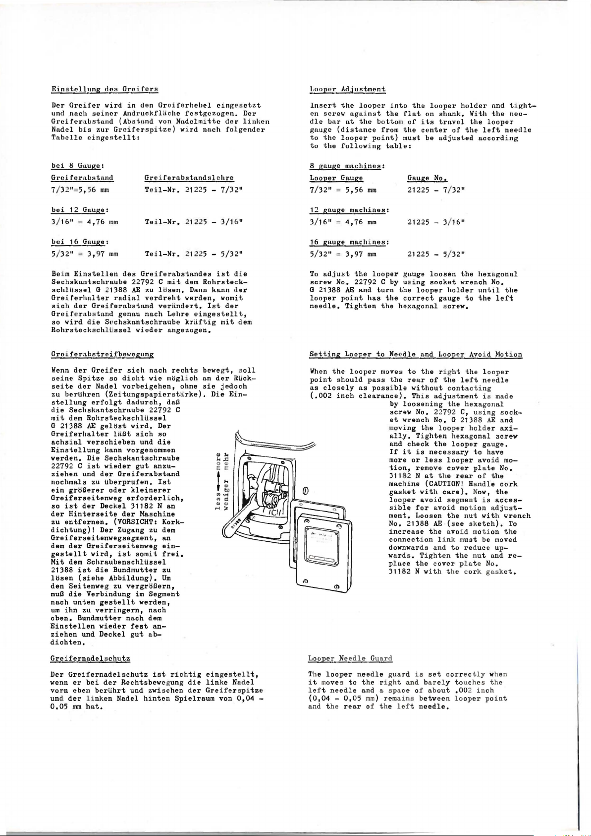
Grciferabstreifbevegung
Wenn
seine
seite
zu
bertihren
stellung
die
Sechskantschraube
mit
dem
G 21388
Greiferhalter lli
achsial
Einstellung
werden.
22792 C
ziehen
nochmals
ein
groBerer
Greiferseitenweg
so
ist
der
Hinterseite
zu
entfernen.
dichtung)!
Greiferseitenwegsegment,
dem
der
gestellt
Mit
dem
21388
losen
den
Seitenweg zu
muO
die
nach
um
ibn
oben.
Einstellen
ziehen
dichten.
Greifernadelschutz
Der
Greifernadelschutz
wenn
vor n
und der linken
0,05
and
56
mm
Gauge:
4,76
rnm
Gauge:
97
mm
Einstellen
des
22792 C
G 1388
der
Greiferabstand
rabstand
die Snchskantschraube
der
Greifer
Sp1tze
der
Nadel
erfolgt
Rohrsteckschltissel
AE
gelost
verschieben
Die
ist
und
der
zu
der
Deck
Der
Greiferseitenweg
wird,
Schraubenschltissel
ist
die
(siehe
Verbindung
unten
gestellt
zu
verringern,
Bundmutter
wieder
und
Deckel
er
bei
eben
bertihrt
mm
hat.
AE
radial
genau
ssel
sich
so
dicht
vorbeigehen,
(Zeitungspapierstli
dadurch,
wird.
Ot
kann
vorgenommen
Sechskantschraube
wieder
Greiferabstand
tiberprtifen.
oder
kleinerer
erforderlich,
el
31182
der Maschi
(VORSICHT:
Zugang
ist
Bundm
Abbildung).
vergroOern,
nach
fest
gut
der
Rechtsbewegun
und
Nadel
Grc i
ferabstandslchre
Tc
il-Nr.
Teil-Nr.
Teil-Nr.
Greiferabstandes
zu
verdreht
nach
vieder
nach
vie moglich
22792 C
sich
und
gut
anzu-
zu
somit
utter
im
Segment
werden,
nach
dem
an-
ab-
ist
zwischen der
hinten
21225 -
2122 5 -
21225 -
mit
dem
losen.
verden,
verlindert.
Lehre
krliftig
angezogen.
rechts bevegt, soll
ohne
rke).
daa
Der
so
die
Ist
Nan
ne
Korkdem
an
einfrei,
zu
Um
richtig
g di e
Spielraum
ist
Rohrsteck-
Dann
kann
Ist
eingestellt,
an
der
sie
Die
ein
lin
Greifer
von
7/32"
3/1
6"
5/32"
die
der
vomit
der
mit
dem
RUck-
jedoch
Ein-
ge stel
lt,
ke Nadel
spitze
0,04
8
gauge
machines:
Looper
7/32" = 5,56
12
3/16" = 4,76
16
5/32" = 3,97
To
screw
G
looper
needle.
Se
When
point
as
(.002
Looper N
The
i t m
-
l ef t
(0,04 -0,05
an
Gauge
gauge
machines:
gauge
machi
adjust
21388
tting
closely
d t he
the
No. 22792 C
AE
point
Tighten
Looper
the
looper
should
inch
eedle Guard
looper needle
oves to
needle
rear
mm
mm
nes:
mm
looper
turn
has
the
the
to Nee
moves
pass
possible
m
machine
gasket
ment.
No. 21388
increase
connection
downwards
ward
place
by u ing
the
by
screw
et
m
ally.
and
If
tion,
311
looper
si
and
as
clearance).
31182 N
gua
t he r
ight and
and a s pa
mm
) r em
of t he l e f t
Gauge No.
21225 - 7/ 32"
21225 - 3/ 16"
21225 - 5/
gauge
the
looper
correct
hexagonal screw.
dle
and Looper
to
the rig
rear
without
Th1s
loosening the
No. 22792 c, us i ng s
wrench
oving
the
Tighten hexagonal
check
it
is
ore
or
remove
82
Nat
with
avo i d segment i s
ble
for
Loosen
s . Ti
the
rd
is set
ce
of about
ains betw
needle.
32"
loosen
socket
holder
gauge
ht the l ooper
of
the
contacting
adjustment
No. G 21388
loop
the
looper
necessary
less
looper
cover pla
t he
(CAUTION
care).
avoi d moti
the
AE
(see sketch).
the
avo i d motion t he
l i nk m
and
to red
ght
en
cover
with
t he
cor re ct l y when
ba r el y touch
een l ooper poi nt
the
hexagonal
wrench
unt1l
to
the
Avo
i d Mot i
left nee
i s made
hex
agon
er
holder
gauge.
to
avoid
rear
of
! Ha
ndle
Now,
on adju
nut
with wrench
ust
be
uce
the nut
pl at e No.
cork gask
es
,00
2
in
No.
the
left
dle
al
ock-
AE and
axi-
screw
have
mo-
te
No.
the
cork
the
acces-
moved
up-
and
et.
t he
ch
on
st-
To
re-
Page 6
Einstollcn
Stelle
Nadelohroberkante
unter
bei
ihrer
rechten
dns Nn
Greifers voll
st
ellung
ausgefUhrt,
Nadelstangenmitnehmer lost und
Nadclstange
tie
fer
Einstellung
Die
Einrich~ung
lango
gestclls
Diose
gii
nglich nach
Ve
rschluCschr.
auf
der
hi
nter
liegende
31133 K
drehung
Transport
Eine
Schrnube
eine
gr o
Oere
Einstellung
Stichlunge
darauf
Transporteur
mnlen
vorn
plnttenschlitz
erfolgter
Stichliinge
Schraube,
schluaschraube wieder
dcr
Nndol st nngc
die
Nndelstnnge
der
Greiferspitze
Bewegung
Seite
delohr
der
muC
sichtbar sein.
der
Nadelstnnge
daC
nnch
stcll
t.
dcr Einfachtr
befinclet sich
(siehe
Einrichtung
der
Entfernen
22539 D u.22 5
Hnndrndseite.
VerschluOschraube
Ansntz-Schraube
vird
<lurch
gelost
Verschieb
kleinere,
seg
nnch
ment
ung
unten
und
nach
Stichlnnge.
der
von
achten,
hinten
ca.
noch
zu
Spielraum
und
nufweist.
Einstellung
ist
die
sovie
so
dcr
rechten Nadel
ist,
nach
rechts
rechten
unt
or
der
man
die
Pratzschrnube
Erfordernis
fUr
die
Einstellung
i n
der Sii
Abbildung).
vird zu-
der
Di e
Linksin
dem
verschoben.
der
Ansatzergibt
oben
Bei
groCten
4,5
mm
daC
der
den
mini-
von
0,5
ch-
mm
im Sti
Nach
der
Ansatz-
die
Ver-
gut
hoch
Nadel
Unterknnte
wird
nns
71
ei ne
ist
anzuziehen.
ein,
wenn
mit
Die
in
dann
hoher
port-S
ule
dna
1,2
sich
der
deckt,
Hoheneinder
Weise
die
oder
t 1
chl
der
des Zyli
22571
die
mm
diose
d.h.
des
im
nnge
Stich-
nder-
31133 K
22539
Height
Set
tha
right
the
looper
to
the
right
the
needle
screw
Adjus
The m
located
D
of
the
needle
needle
point
right
side
of
bar
No. 22562
ting
the
Differential
echanism
in
the
Needle
eye
and
the
bar
so
is 3/64"
when
its
right
height
Bar
that
the
point
loosen
A.
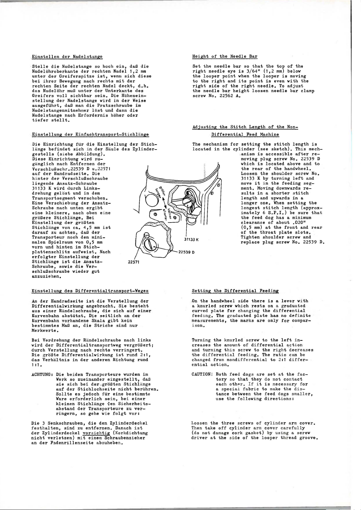
Stitch
Length
Feed
for
setting
cylinder
.
anism
moving
which
the
rear
Loosen
31133 K by
move
ment.
sults
length
longer
longest
imately 6 S.P.I.)
the
feed
clearance
(0,5
of
the
Tighten
replace
the
tov
mm)
is
even
To
needle
the
of
below
moving
with
adjust
bar
Non-
(1,2
looper
is
needle.
of
Machine
the
it
(see
is
plug
is
the
i n
stitch
sketch).
accessible
screw
located
of
the
shoulder
turning
the
length
No. 22539 D
above
handwheel.
left
feeding segMoving downwards
in a shorter stitch
and
mm)
one.
throat
upwards
When
stitch
dog
of
at
the
shoulder
plug
length
has
about
front
plate
screw
in
setting
be
a mi nimum
.020"
screw
No. 22539
the
the
clamp
This
after
screw
a
(approx-
sure
and
slots.
and
and
and
re-
is
mech-
re-
to
No.
the
tha
rear
t
D.
Ein
st e
llung
des Di f f er e
An
der
Differentialwirkung
nus
Kurvenbahn
Kurvenbahn
bestimmtes
Handradseite
einer Randelschraube,
nbstUtzt.
vorhandene
MaC
an,
Merkverte.
Bei
Verdrehung
wird
durch
Die
gr o
das
Verhaltnis
der
Verstellung
Ote Differentialwirkung ist
der Rundelschraube nach
Differentialtrans
in
1:1.
ACHTUNG:
Die
he i
Werk
so
sie
sich
auf
der
Sollte
Ware erf
kleinen
abstand
den Trans
zueinander
Stichloch
es
orderlich sein, bei ein
Stichl
der
ringern,
Die 3 Senkschrauben,
f es t h
alten,
der
Zylinderdeckel
nicht
an
der
sind
verletzen)
Fadenrillen
zu
mi t einem
ntinltransport-Wege
ist
die
angebracht.
Die
die
nach
der
Verstellung
die
sich
seitlich
Skala
gibt
Striche sind
p
ortweg
rechts
anderen
verr
Richtung
Sie
porteure
ei ng
bei
der.groCt
jedoch fUr
ange
Transporteu
so
gehe v i e
die
den
entfernen.
sei
en St i
te
eine bes
~e
n
fol
Zyl
Dana
estellt,
nicht
Si
r e
i nd
vorsicht i g (Kor kdi
te
Schraubenz
abz
uhebe
n.
sei
der
be s
teht
auf
einer
an
der
kein
nur
link
vergroCert;
i ng
ert.
rund 2:1,
rund
wurden
chl
ange
bertihren.
timmte
er
cherheits-
zu
ver-
gt vor :
erdec
kel
ch ist
chtun
i eh
er
s
im
dna
g
Setting
.
On
a
curved plate
feed1ng
measurements,
ison.
s
Tur
creases t he amount of differential act i on
and
t he d
ch
e
ntial act
CAUTION! Both fee
Loos en
Th
(do not d
drive
the
Differential
the
handwhee l s
knurled screw whi
for changi
. The
graduated pla
the
ning
the
knu
rled screw
tur
ni ng t
ifferentia
ang
ed from no nd
his scr
l feedin
i on .
tory
so t h
each o
thP
a s pecial fabr
tan
ce
between the feed
u
se
t he f ol
the
t h
en t ake o
r a t
ama
the
ree
ff
ge co
cyl
sid
Feeding
ide
there
ch
is a lev
rests
on a gr aduat ed
ng
the diff
te
are
to
g.
i t
i c
t)
has
onl y
to
the
the righ
The
to
set
do n
is nece
to make
direct
cov
by
marks
ew
ifferenti al
d do
gs are
at
they
r .
If
lowing
screws of cylinde
ind
er arm
rk gaske
e of t he l ooper thread g
erential
no definit
for
left in-
t decr
rat
i o can be
2:1 d
at
ot conta
ssa
t he
dogs
i on s :
r ar m
er
carefull
using
er wi
compa
iff
the fac-
ry f
dis
smalle
a s cr
eas
er-
ct
cove
y
roove.
th
e
r-
es
or
r,
r .
ew
Page 7
D
ie
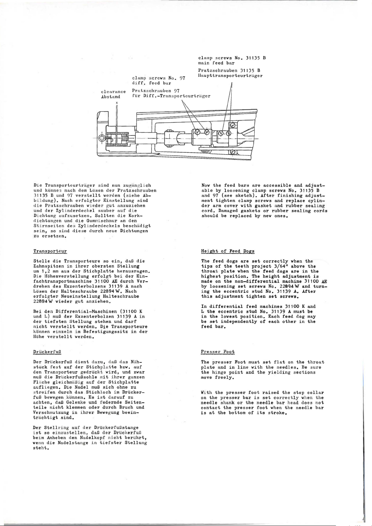
Transporteurtriiger sind
und lliinne'l
) 1135 B und 97
b
il
dung).
die Pratzsch
und
der
chtun
Di
dichtungen
Stirnsei ten des
sein,
zu
crsetzen.
nnch
dem Losen der
verstellt werden (si
Nach erfolgt
rnuben w1eder g
Zyl1nderdeckel
g uufz
usctzen.
und
die
Zyl
so sind
die e durch
clca~rnnce
Ab
st a
cr Ei ns
ut
sauber
Sollten
Gummischnur
i n
derdecl<
els
neue
clamp
di
ff. feed bar
Pr
at zs chraub
fli r Di
nd
nun ZUI(ilngl 1
Pratzschrnuben
ehe
tellung sind
anzuziehen
auf
di e
die
Kork-
an
den
beschiidigt
Dichtungen
sc r ews No . 97
en 97
ff
.-Tr
ansporteur
ch
Ab-
clamp screws
mll
in feed
Prntzschrnuben
ll~tupttransporteurtriige
No.
b~tr
311
31135 B
t ritge r
Now
the
feed
a
ble
and
97
ment
der
arm
cord.
should
by
tighten
Damaged
loosening
(see
sketch).
cover
be
replaced
bars
clamp
with
gaskets
35
B
r
are
accessible
clamp
screws
After
screws
gasket and
or
rubber
by
new
No. 31135 B
finishing
and
replace
rubber
ones.
and
sealing
adjustadj
ust-
cylin-
seal
cords
i ng
Transportcur
Stelle
Zahnspitzen
urn
Di e
die
Trnnsporteure
in
1,2
mm
llohenverstellung
aus
i h
der
fachtransportmaschine
drehen
Losen
erfolgter
22894 W wieder
Bei den Di
und L)
der
nicht
konnen
Hohe verst
des
Exzenterbolzens
der
Halteschraube
Neueinstellung
gut
fferential-Maschinen
muO
der
tiefsten
verstellt
einzeln
Exzenterbolzen
Stellung
i m
ellt
werden.
werden.
DrlickerfuO
Der
Drii
stuck
f est
den Trans
mua
di e Dr u
Flnche
auflieg
s
fu
a
teile nicht
gleichmuiJ
en.
treifen
O bewegen k
chten,
daO
Verschmutzung
trnchtigt
Der
Stell
i
st
so einzust
be
i m Anheben d
we
nn die Na
ckerfuiJ
client d11zu, daO d
auf
der
porteur gedrticl
ckerfuOsohle mit ihrer
i g a
Die
Nadel
durch
das
onnen.
Gelen
klemmen
in ihrer
sind.
ring
auf d
ellen,
en Nadelkopf ni
delstange
steht.
so
rer
obersten
Stichplatte
erfol
ein,
gt be i
31100
AE
31139 A
22894~.
Halteschraube
Stellung
herausragen.
anziehen.
31139 A
stehen
und
Die
Transporteure
Befestigungssitz
Stichpln
uf der Sti
Stichloch
Es
ke und f
oder
<t
mua
sich
i s t dar a
edernde
durch
tte
wird,
chplatte
ohne
i m
Bewegung
er
DrUckerf
uOsta
daB der Drtickerf uO
t i ef
cht
ster
in
dna
die
der
E1n-
durch
Ver-
nnch
Nach
(31100 K
dar
f
in
as Nuh-
bzw.
auf
und
zwar
ganzen
zu
DrUcker-
uf
zu
Seiten-
Bruch
und
beein-
nge
bertihrt,
Stellu
in
der
ng
Height
The
tips
throat plate
highest
made
by
i
this
In
L
in
be
feed
feed
of
on
loosening
ng
the
adjustment
differential
the
eccentric
the
set
bar.
of
Feed
dogs
the
position.
the
eccentric
lowest
independently
Pr esser Foot
The pr ess
plate and
the
move
Wi t h
on
needle
contact
is
er
in
hi nge
point
freely.
the
presser
the presser
shank or
the
at
the
bottom
Dog
s
are
set
tee
t h
when
non-differential
set
position.
Foot
line with
bar
correctly
project
the
feed
The
height
screws
stud
tighten
feed
stud
No. 31139
machines
No. 31139 A m
of
must
set
and
t he n
the
foot raised
is
set correct
the needle
presser foot
of its stroke.
when the
3/64"
above
are
in
the
t he
dogs
adjustment
machine
No.
229q4~
set
screws.
31100 K
Each
feed
each
other
fla
t on
eed
yi e
lding sectio
t he stop
ba r head do
31100
and
A.
After
and
ust
be
dog
may
in
t he
the thr
l e s . Be sure
ns
collar
l y when the
es not
when t he needl e bar
is
turn-
oa t
AE
Page 8
Drtickerful3feder
Stelle
dal3
wie
erforderlich
befindet
hinter
den
der
zum
Druck
Drtickerful3
gleichmlil3igen
sich
der
Nadelstange.
ist.
oben
der
Drtickerful3feder
nur
so
Transport
Die
Regulierschraube
auf
dem
viel
Druck
der
Maschinenarm
so
erhnlt,
Ware
ein,
Pressure
The
pressure
sc
rew
to
the
presser
enough
fabric.
on
located
needle
foot
pressure
the
Presser
regulating
on
top
bar.
spr
i ng
for
of
Set
so
proper
Foot
screw
the
the
that
is
machine
pressure
there
feeding
the
i s
knurled
arm
of
just
of
the
next
the
Einfndeln
Flidle
ein
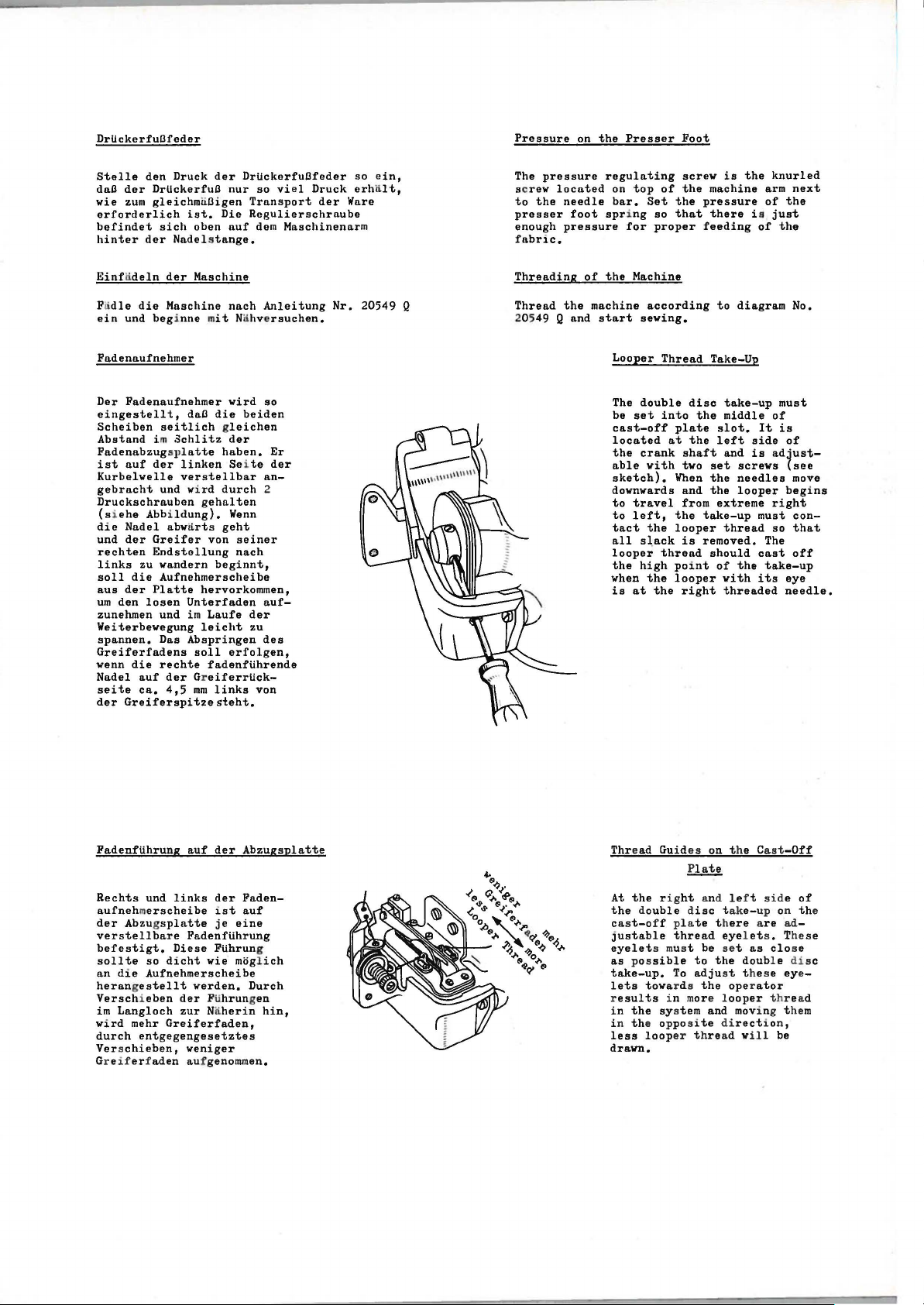
Fadenaufnehmer
Der
eingestellt,
Scheiben
Abstand
Fadenabzugsplatte
ist
Kurbelwelle
gebracht
Druckschrauben
(siehe
die
und
rechten
links
soll
aus
um
den
zunehmen
Weiterbewegung
spannen.
Greiferfadens
wenn
Nadel
seite
der
der
Maschine
die
Maschine
und
beg
i nne m
Fadenaufnehmer
auf
Nadel
der
zu
die
der
die
auf
ca.
Greiferspitzesteht.
dal3
seitlich gleichen
i m
Schlitz
der
linken
verstellbar
und
wird
Abbildung).
abwnrts
Greifer
Endstellung
wandern
Aufnehmerscheibe
Platte
losen
Unterfaden
und
im
Das
Abspringen
soll
rechte
der Greiferrtick415
mm
nach
Nahv e
wird
heiden
der
haben.
Sei
te
durch
Wenn
geht
seiner
nach
der
zu
erfolgen,
Anleitung
rsuchen.
so
Er
der
an-
2
auf-
des
von
it
die
gehalten
von
beginnt,
hervorkommen,
Laufe
leicht
fadenftihrende
links
Nr.
20549 Q
Threading
Thread
20549 Q
the
and
of
the
machine
start
Looper
The
be
cast-off
located
the
able
sketch).
downwards
to
to
tact
all
looper
the
when
is
Machine
according
sewing.
Thread
double
set
into
at
crank
with
travel
left,
the
slack
thread
high
the
at
the
disc
the
plate
the
shaft
two
When
and
from
the
looper
is
point
looper
right
to
diagram
Take-Up
take-up
middle
slot.
left
and
set
screws
the
needles
the
looper
extreme
take-up
thread
removed.
should
of
the
with
threaded
must
of
It
is
side
is
ad~ust
right
must
so
The
cast
take-up
its
No.
of
(see
move
begins
conthat
off
eye
needle.
Fadenftihrung
Rechts
aufnehmerscheibe
der
Abzug
verstellbare
befestigt.
sollte
an
die
herangestellt
Verschieben
im
Langloch
wird
mehr
durch
entgegengesetztes
Verschieben,
Gr ei ferf
auf
der
Abzugsplatte
und
links
der
Faden-
ist
splatte
Fadenftihrung
Diese
so
dicht
Aufnehmerscheibe
werden.
der Fti
zur Naherin
Greiferfaden,
weniger
aden auf genommen.
je
Ftihrun
wie
hrungen
auf
eine
moglich
g
Durch
hin
1
Thr
ead Gui d
es
on
t he C
ast
-Off
:ll!!:i!
At
the rig
the double disc take-up on the
cast-o
justable
eyelet
as
pos
take-up.
lets
r
esults
the sys
i n
th
i n
less
drawn.
ht
and lef t
f f pl a
te
t h
thread
s must be set
sible
To
towa
r ds
i n more l
tem
e opposite direct
loop
er
ere are
eyelet
to
the
adju
t hread will be
doubl e disc
st t hes e eye-
the
oper
ooper
and
mov
side of
ad
s . These
as
clo
ator
t hr ead
i ng them
i on ,
-
se
Page 9
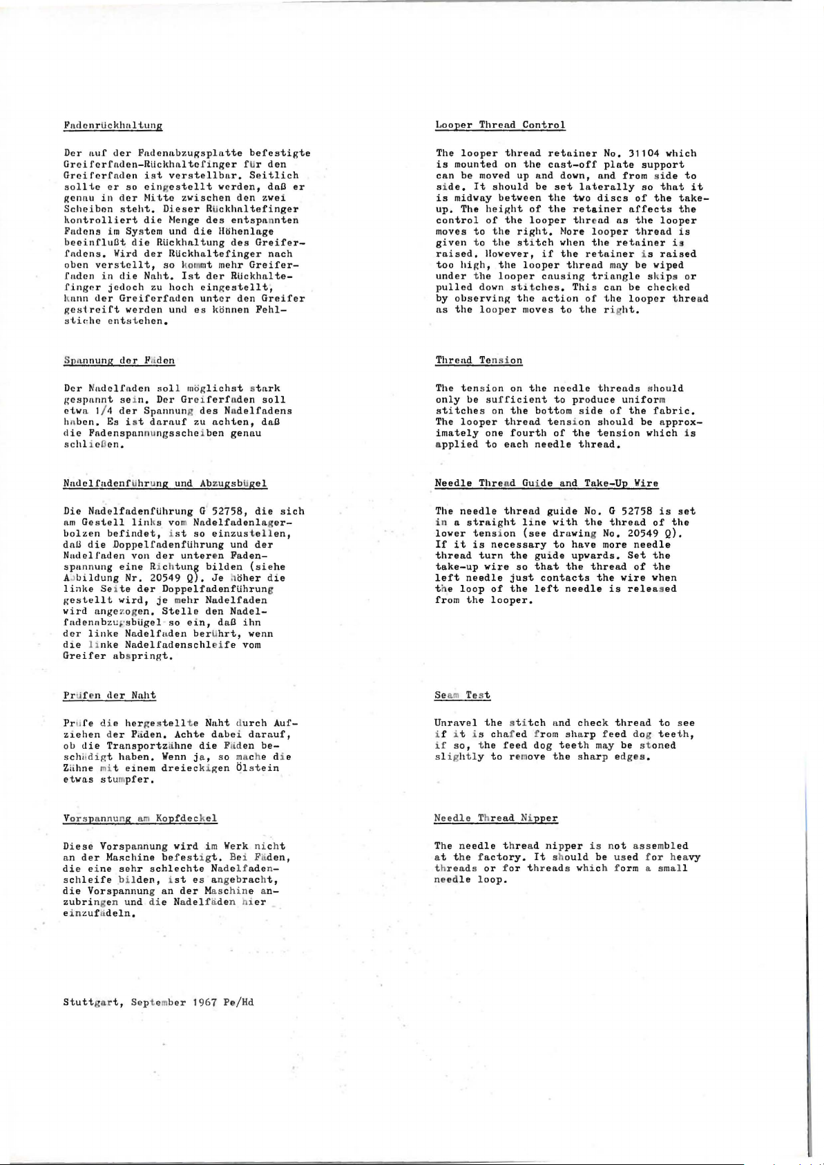
FnclcnrUck
Dcr
Gre i
Grcifcrfnden
sol
gcnnu
Scheibcn
ltontrolliert
Fudens
hnltung
nuf
der
fer
fnden-RUclthl\1
ltc
er
so
in
cler
steht.
im
System
Fndennbzugsplntte
ist
eingestellt
Mittc
die
beeinfluat die
fndens.
o
ben
fadcn in
fingnr
k
ann
ges
Wird
verstcllt,
jcdoch
der
trcift
die
Gre
verden
der
Nnht.
zu
iferfnden
stiahe entstehen.
tcfinger
verstellbnr.
zwischen
Dieser RUckhnltefinger
Menge
und
die
RUckhnltung
RUckhnltefinger
so
kommt me
Ist
hoch
cingestellt,
unt
und e s kijnnen
f Ur
Seitlich
verden,
den
des
entspannten
H~henlnge
des
hr
der
Greifer-
RUckhnlte-
er
den
zwei
Greifer-
Greifer
Fehl-
befestigte
den
dna
nnch
er
Looper
The
looper
is
mounted
can
be
s i
de.
is
midway
up.
The
control
moves
given
raised.
too
high,
under
pulled
by
observing
as
the loope
Thread
thread
on
moved up
It
should
between
height
of
the
to
the
to
the
However,
the
the
looper
down stit
Control
the
and
be
of
looper
right.
stitch
if
looper
causing
ches.
the
action
r moves
retainer
cast-off
down, nnd
set
laterally
the
tvo
the
retainer
thr
More
when
the
thread
This
to
the
No.
plate
discs
ead
looper
the
retainer
mny
triangle
can
of
the
ri
31104
support
from side
so
of
the
affects
as
the
thread
retainer
i s
be
wiped
sl ips
be
chec
looper thre
ht.
which
that
takethe
looper
is
i s
raised
ked
to
or
it
ad
Spn
nnung
dcr Fft
dcn
Dcr
Nadclfnden
gcs
pann t sei
ctw
n 1/ 4
hn
ben.
die Fndenspnnnungsscheiben
schli ellen.
Es i st
Nadclfadenftihrung
Die
NndelfndenfUhrung
am
Gestell
bolzen
dnU
Nadelfnden
span
AJ
li<~l<e
gestellt
wird
fndennbzuFsbUgel
der
befindet, ist
die
DoppelfndenfUhrung
nung
bildung
Se1
nnge zog
linke
die linke
Greifer abs
Prtif
en
der
Prufe
di e
ziehen der Faden.
ob
die
schit
Zlihne mit
Trnnsportz
digt haben.
et wns stum
soll
n.
Dcr Grei
der
Spnnnung
dnrnuf
und Abzu
linl
ts vo
von
der
cine
Richtun~
Nr.
20549 Q).
te
der
wird,
Doppelfadenftihrun
je mehr
en.
Stelle
Nadelfuden
so
Nadelfndenschl
pringt.
Nnht
her
ge s
tell
Achte
lihne
Wenn
einem
dreiec
pfer.
mijg
lichst stark
ferfnden
des Nudelfndens
zu
nchten,
G
52758,
Nndelfndenla.gerso
einzus
unter
en
bilden
Je hijher
Nndelfa.den
den
ein,
berUhrt,
eife vom
t e
Naht durch
dnbei dnrnuf,
die
j a , so mache d i e
ki g
gennu
gsbugel
die
t ellen,
und
der
Fnden-
(siehe
Nndel-
dna
ihn
wenn
Fj d
en
en blstei
soll
dna
die
g
be-
sich
Auf-
n
Thrend Tens i on
The
tension
only
be
looper
needle
tens
it
is
needle
loop
the
sufficient
on
thread
one
to
each
Thre
ad Gui
thread
i on
necessary
turn
wire
of
looper.
stitches
The
imately
a
pplied
Needle
The
in a straight
lower
If
thread
take-up
left
t he
from
Seam Test
Unravel
i f i t i s
if
sl i ghtly
the
so, the
chafed
feed
to rem
on
the
needle
the
to
bottom
tension
fourth
of
needle
de
guide
l i
ne
with
(see
drawin
the
just
the
st i
to
guide
so
that
contacts
left
tch nnd check
f rom
dog
teeth may
ove
the shar
threads should
produce
side
of
should
the
tension
thread.
and
Take-Up
No. G 52758
the
thread
g No. 20549 Q).
have
more
upwards.
the
thread
the
needle
is
sharp feed
p e
unifor
the
be
Wire
needle
Set
of
wire
released
thread
dog
be
st on
dges
m
fabric.
approx-
which
is
of
the
the
when
to see
teeth,
ed
.
set
the
i s
V
ors
pannu ng am Kopf
Di
ese
Vors
nn
der
di
e ei
leife
s ch
die
zubri
einzufrideln.
Stuttgar
pan
Mnschine bef es t i g
ne sehr
bi l
t,
den, ist
Sept em
Vorspannung an
ngen und die Nadelfli
nung
wird
schlechte
ber
deckel
i m We
es ange
der
Mas c
1967
rk nicht
t.
Bei Fa
Nnd elfade
bracht,
hin
e a
den hi
er
Pe/Hd
den,
n-
n-
Needle
The n
at t he factory.
t h
need
eedle
reads
le loop.
Thread Ni
or for thr
t hread
pper
nipper
It should
ead
s which f orm a
is not
be used
ass
embl
f or hea
smal
ed
vy
l
Page 10
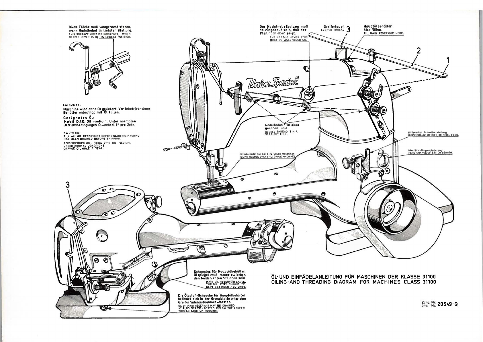
Oi
ese Fliich
wenn Nodelhebel
THIS SURFACE
NEEDLE
Beochte:
Mas
chino wird ohne
Be
hiil
Geeignetes Ol:
Mobil
Betr
CAUTIO
FILL ALL OIL RESE
HAS BEEN
R
ECOMMEND
UND
ER
'"~£
e muD waagerecht stehen,
HUST BE
LEVER
ter unbedin
O.T.E.
Oil
ie
bsbtdingungen Olwech
N:
RVO
DRAINED BE
ED
OIL: H
NORM
AL C
ONDmON
OIL ONe.£ A YEAR.
in
tiefster
HORIZONTA
IS IN
ITS
LOWEST
Ol Qtli
efert. Vor
gt
mit
Ol
fullt n.
med
ium. Untor normolen
ul
IRS BEFORE S
OBI
TARTING. MACH
FOR
E SHIPPING
L D T.E. OIL HEDJUH.
S
Ste
llu
L WHEN
POS liON
lnbetriebnohme
1"
pro Johr.
ng.
Gre
iferfade n 3
LOOPER THAEA
.
INE
O
Hauptlilbehtilt
hier filllen.
Fi
ll MAIN
tr
RESERYOUt HER£ .
OL-UND
EINFADELANLEITUNG
OILING-AND
THREADING DIAGRAM
FUR
MASCHINEN
FOR
MACHINES
DER
KLASSE 31100
CLASS 31100
~~g.~
20549-Q
Page 11
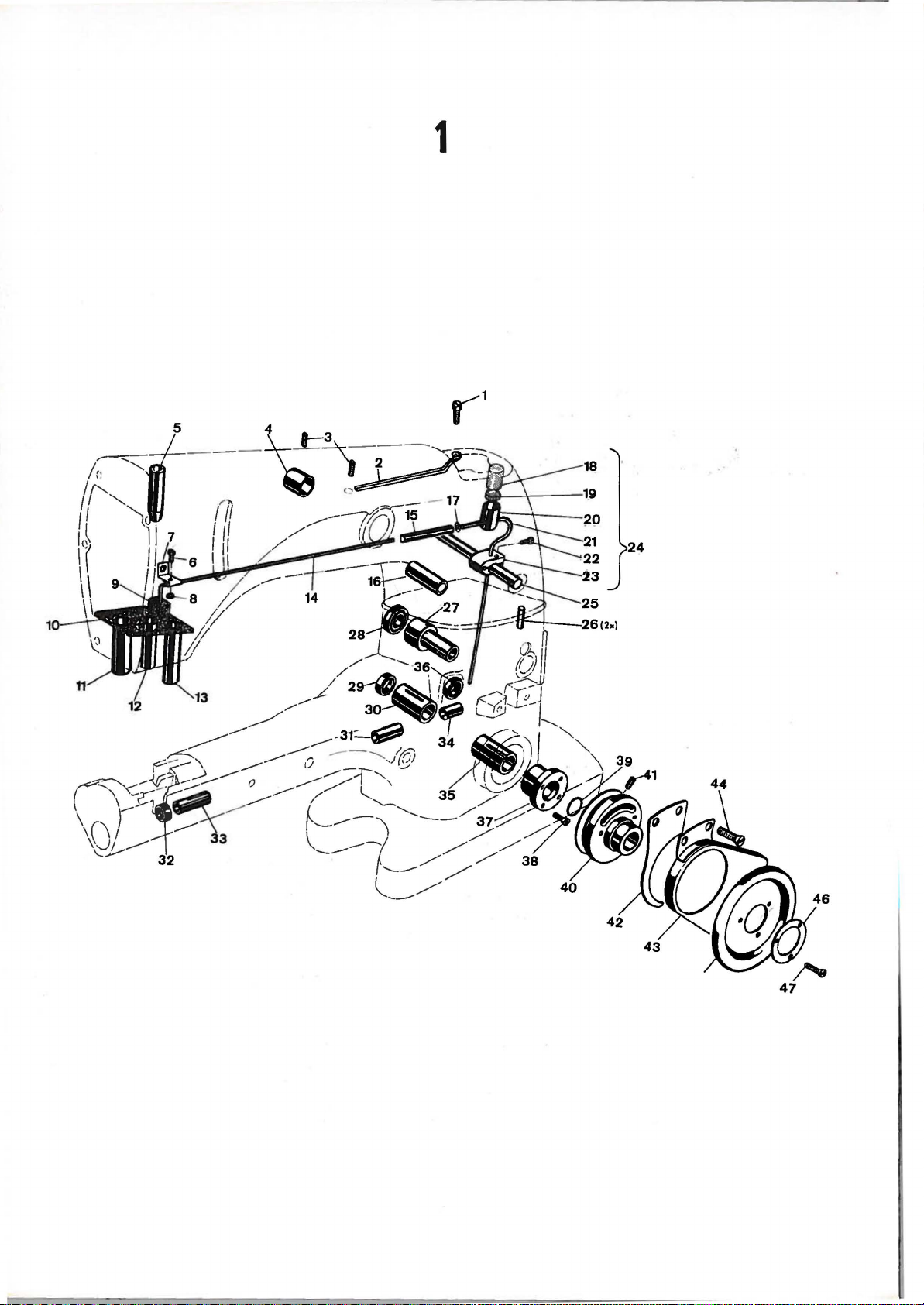
1
Page 12

Po
Ref.
s .
Nr.
No.
Tcil
Part
Nr.
No.
B e z c i c h n u n g
D
~
s c r i p t i o n
~
Amt.Reg.
10
11
12
13
14
15
16
17
18
19
20
21
22
23
24
25
26
27
28
29
30
31
32
33
34
35
36
37
38
39
40
41
42
43
44
45
46
47
1
2
3
4
5
6
7
8
9
90
33782
AE
719
51150
51254 c
87 u
31194 A
43443 Q
666-214
31194 B
31178
51254
D
31155
31194
51294
N
52883 R
Schraube
!hrinne
Schraube
AnschlagbUchse
N'Stge'BUchse
oben
Schraube
!hrohrhal
ter
Mutter
Pilz
Pilz
D'P'PUhrungsst
N'Stge'Btich
angenbU ch
se
unten
D'P'StangenbUchse
Olrohr
Olsiphon-Verbindung
D'P'Lifter
BU
chse
se
Screw
Needle
Screw
Needle
Needle
Screw
O
il
Tube Clamp
Nut
Felt
Lint
Felt
Bushing
Needle
Bushing
Oil
Si phon Tube
Oil
Tube
Presser
Lever
Lever
Bar
Bushing,
Filter
for
Presser
Bar
Bushing,
for
Presser
Connection
Foot
Bearing
Shaft
Lifter
Oiler
Stop
upper
Guide
Lower
Bar
Lever
2
Collar
Bar
Bushing
21212
Ring
f.Olsiphon-Verbindung
Oil
Siphon
Connection
Lockin
g
Ring
666-201
666-209
G 50-521
G
50-520
75
53394
53394 Q
21657 X
80699 A
31142 c
999-1
999-35
31190
31140 A
999-36
31140
31140
31190
999-37
31191
22569
660-202
31121 A
22894 G
31175 c
31275
22581
61321
61321 L
22574
R
B
B
A
B
J
Olfilz
Pilzscheibe
Trichter
f.
Olrohr
Olrohr
Schraube
Halter
Olsiphon
f.
kompl.
Ols
i phon
BUchse
PaLls
tift
Bundbuchse
Simmerring
Simmerring
Hauptwellenbuchse
Greiferachsbuchse
Simmerring
Greiferachsbuchse
Greiferachsbuchse
Buchse
Simmerring
nur
Kurbelwellenlager
Schraube
0-Ring
Handrad
Schraube
Stoffschutz
Handradschutz
Schraube
Handrad
Sch
(Kunst s
eibe
Schraube
f.D
toff)
links
iff.Trsp
Felt
Plu
g
Siphon
Cup
Disc,
felt
Siphon
Oil
Tube
Screw
Oil
Oil
Siphon
Siphon
Clamp
Assembly
2
Bushing
Pin
Bushin
g
2
1
Gasket
Gasket
Crankshaft
Bushing
for
Bushing
Looper
Bar
Gasket
Bushing for
Bushing
for
Looper
Looper
Bar
Bar
Bushing
.
Gasket for Diff
Crankshaft Bushin
includ
i ng bush
Screw
. P
eed
g Hou s ing,
ing
onl y
4
O"Ring
Pulley
Screw
Clot
h Guard
2
Belt-Guard
Screw
Handwheel
Wa
she r
Screw
2
1
1
3
Page 13

2
Page 14

Pos.
Ref.
34
40
41
42
43
44
46
47
48
64
10
11
12
13
14
15
16
17
18
19
20
21
22
23
24
25
26
27
28
29
30
31
32
33
35
36
37
38
39
45
49
50
51
52
53
54
55
56
57
58
59
60
61
62
63
65
66
67
68
69
70
71
72
73
74
75
76
77
78
79
ea r
nt
AE
Anzahl
Amt.Rcq.
1
4
1
1
1
4
1
1
2
1
1
2
1
1
1
1
1
2
1
1
1
1
1
1
1
1
5
1
1
1
1
1
1
1
1
1
1
1
1
1
1
1
1
2
1
2
1
1
1
1
1
1
1
2
1
1
1
2
1
1
1
1
1
2
1
1
1
1
2
4
1
1
1
1
1
1
1
1
1
Nr.
No.
1
2
3
4
5
6
7
8
9
Tcil
Nr.
Part
No.
31191 A
c
22839
22539
33782 E
31182
99274
33782 B
33782 y
90
52882 p
D
N
31282 D
n
22541
52882
AD
39582 L
52882
AC
50-789
52882
AA
90
31158
B
95
22768
31158
A
33782
A
31170
22565
31182 A
22569
22569 D
WD
57
57
we
57
WB
31158
E
31117
33758
D
52758
G
22768
22889 A
20
22848
99287
99287 B
11182
99287 c
999-41
31182 D
96402
31182 D- 1
31163 A
31182
L
31182 R
31182
B
31158
D
22570
M
129
C
31182
T
31182
s
31182
K
22766
31182 c
31158
c
77
K
31183
999-78
99242
22733 B
G
50-434
41394 A
33782 c
22585 A
90939
31138
H
11638
M
HA 86 B
9Q9-32
99292
31258
96201
11638
M
22571
B c z c i c h n u n g
Dichtung
Schraube
VerschluOschraube
verstellung
Dichtung
De
ek
e 1
Schraube
Dichtung
C
lspritzblech
Schraube
Dichtung
Schr
aube
Schraube
Armdeckel
Klappdeckel
Feder
Stitt
C
lfangblech
S
chraube
Fadenleitbiigel
Sch
raube
S
chraube
Fa
denfiihrung
kompr.
auf
f.
N'Stange
Kopfdeckeldichtung
Padenabzugshaken
Schraube
1\opfdeckel
Schraube
Schraube
h
nsatzschraube
Fadenspannungsfeder
Fadenspannungsplnttchen
Fadenspannungshalter
plnttchen
Nadelstange
Fadenfuhrung
PadenfUhrung
Schraube
VerschluO
Sche
i be
Schraube
Schraube
Schraube
Zylinderdeckel
Schraube
Gummischnur f.J
Scharnierdeckel
Nie
t
Sch
arnierdeckel
Dlattfeder
Dichtung
Dichtung
HaltebUgel,vorn
PadenfUhrung, hinten
Schraube
Niet
Halteblech
Spritzlapper.
Olspritzblech
Schraube
HaltebUgel,
Fader.fUhrung,
Schraube
Scharnierschraube
VerschluO-Stopfen
Schraube
C
lablaOschraube
Olstandsau
Dichtungsring
Dichtung
Schraube
Schraube
Stift f .
!·
Iutter
Federscheibe
Di
chtring fiir
Sch
raube fiir Klasse 31100
F
adenosenhalter
Pederring
Mutter
Ver s
chluOschraube
siehe
am
u.
Aufnahme-Schr.
hinten
f.31182
ge
Zu
fede
f Ur Klasse 31100
fiir
-
Seite
Nadelhebel
1182
kompl.
vorn
B
r
Klasse 31100
Klasse
Stic
7
AE
31100
h-
AE
AE
D e s c r i p t i o n
Gasket
Screw
Plug
Screw
Gasket
Cover
Screw
Gasket
Baffle
Screw
Gasket
Screw
Screw
Chamber
Oil
Oil
Oil
Drip
Screw
Needle
Screw
Screw
Needle
Gasket
Pull-off
Screw
Head
Screw
Screw
Nipper
Nipper
Nipper
Needle
Needle
Needle
Thread
Screw
Plug
Washer
Screw
Screw
Screw
Cylinder
Screw
Rubber-str1ng
Cylinder
Rivet
Cylinder
Spr i ng
Gasket
Gasket
Support
Thread
Screw
Rivet
Holding-plate
Splash-leather
Baffle Plate
Screw
Support for
Thread
Screw
Hinge
Plug
Screw
Oi l Dr
Lucite
Gask
Gasket
Sc
Scre
Spr
Nut f
S
AE
Gasket for
S
E
Locking
Nut
Plug
Plate
Cap
Cap
Cap
Hinge
Plate
Thread
Bar
Cover
Spring
Spring
Spring
Thread
Bar
Lever
Eyelet
Screw
for
Eyelet,
Eyelet,
Screw
for
ain Plug
Oil
et
re"
-
w
ing-pin
or Class
pring Wash
crew
f or Class
yelet-Support
Screw
Cover
Torsion Spring
Pin
leading
Thread
~elet
Wire
Screw
Plate
Nipper
Thread
Eyel
Cover
Hinged
Hinged
Cover Ass
Cover
Cylinder
rear
Cyl
inder Cover,r
front
31182
B
Screw
Gauge
31100
f or Cl a
31100
31100
AE
er
Class
Ring
Wire
Bore
et
embly
Cover,fro
ss 31100
AE
AE
Page 15

3
~
17
!
~
~18
19 [
~~~-~
_'0, 1
--
~
·
f:l.ii'
I
di
18
I
3
16
22
15
"
---
~
v12
11K
14
20
I
I
~
~
~
all
Page 16

Po~
Ref.
No.
Teil
Pn
rt
Nr.
No.
B e z e i c h n u n
a
Dcscr
1
t i o n
I'
~
Amt.Rcq.
51216
2
)
660
71
-212
9
4 51250
5
51250
6 22586
7
51150
8 22768
9
10
11
12
13
14 G
15
16 G
17
18
19
20
22
31158
31117
33758
22768
660-212
29476
15430 c
29066 c
G 97
AA
31132
51216 L
311 16
51216 p
23 21559 c
G
24
25
26
27
29348
51250
BP
108
31115 A
28 51250 A
29 6
30
31
66-170
77
54
32 51054
33
34
35
36
666-149
51254
22562 A
78
N
D
F
R
A
D
PA
G
E
H
Scheibe
Schraube
iilabstreifring
U'Legscheibe
Dichtungsscheibe
Schraube
Anschlagbuchse
Schraube
FadenfUhrung
Nadelstan
FadenfUhrung
ge
auf
Nadelstange
am
Nadelhebel
Schraube
iilabstreifrin
g Oi l Sea l
Nadelhebelverbindung kom
Nutter
Kugellager
linlts
kompl.
Schraube
Lagerschale
Kugel
Nadel.hebelverbindung
Nutter
Schraube
Nadelhebel
kompl.
Nadelhebelbolzen
Schraube
Nadelhebel
BUchse
Oldocht
Schraube
Verbindun
Konischer Sti
gsg
elenk
ft
Docht
Mitnehmer
Schraube
Schraube
pl.
Wnsher
Sc rew
Oil
Senl
Ring
Washer
Gaslt
et
Screw
Needle
Lever Shaft Stop
Screw
Needle
Needle
Needle
S
crew
Bar Thread
Bar
lever
Thread
Ring
Needle
Nut
Needle
left
Lever
Thre
Lever
Rod
ad
Ball
Screw
Needle
Lever
Ball
Ball
Needle
Lever
Rod
Nut
Screw
Needle
Need
le
Lever
Lever
Assembly
St
Screw
Needle Lever
Needle
Oil
Wi ck
Lever
Bush
Screw
Pin
Bar
Link
Needle
Link
Lubricating Felt
Needle
Bar
Connection
Screw
S
crew
Eyele
Assembly
Joint
Joint
ud
i ng
2
Collar
t
Eyelet
:!
Be ar i ng
2
2
2
Page 17

~
Page 18

Pos.
Ref.
1
2
3
4
5
6
7
a
9
10
11
12
13
14
15
16
17
18
19
20
21
22
23
24
25
26
27
28
29
30
31
a
32n
(
33
34
35
36
37
38
40
41
42
43
44
45
46
48
50
51
(li;
54
55 -
56
59
60
61
62
63
64
65
66
67
68
69
70
71
72
73
74
qf
84
85
86
DRA
Toil
Nr.
No.
G 29476
Nr.
Part
No.
31139
258
31146
97 A
31139 B
35746
28 B
X
c
22894 c
31206
22559 c
31142 A
999-1
31142 B
22517
31142
12538
c
31144
18
G 97 A
31144 B
97
A
22517
31144 G
15037 A
22733
97
A
31144 D
77B
31144 E
p
31144
31108
B
31108
31110 A
3
31110 B
99312
31113
22792
73
31144
12.559 c
999-39
999-39
311
22 A
75
31116 J
999-38
31116 H
11963
31133 M
999-30
HA
482 A
88
31142
22894 w
31142 M
c
R
w
A
Q
12538
31142 D
22729 L
31116
c
999-40
31106
22894 c
G 22559 C
31144 A
17
462
AA
G 29476
12538
G
12055 N
51054
666-149
31133 J
31133
H
31133 K
999-3
2
31142
p
462
21657 E
B o z e i c h n u n g
Transporthubhebel
Mutter
Scheibe
Doppellager
Schraube
Lagerscha.le
Kugelschraube
Schraube
Schraube
Exzenter
Schraube
Bundach se
Simmerring
Bolzen
Schra.ube
Doppelhebel
Mutter
Kugelschra.ube
Mutter
Schra.ube
La.gerschale
Schraube
Schraube
Greiferantriebsheb
Mutter
Schraube
Schraube
Kugelschraube
Schraube
PUhrungsgabel
Antriebsgel
Greifer
Greifer
Greifernadelschutz
Greifernadelschutz
Schraube
Greiferhalter
Schr
aube
Schraube
Greiferachse
Schraube
Nadelkafig
mit
rot
Nadelkiifi
mit
weiBem
Kurbelwelle
Schraube
Greiferantriebsverbindungsst
Nadelkafig
Nadelhebelverbindung
Kulissenbolzen
Stellmutter
0-Ring
Stellring
Schraube
Transport
hebel
Schraube
Gelenkbolzen
Mutter
Exzenter
Schraube
Transportantriebsverb
Nadellager
Greiferantriebsexzenter
Exzenter
Schraube
Schraube.
Kurbelwel
Gelenk
Schraube
Mutter
Mutter
Gr,Hebel
Gelenkstift
Docht
Verbindungss
Diff.-Tra
Verbindungsstan
Einfach-T
Ansatzschraub
0-Ring
Achs e
Mutter
Scheibe
f.
Transporthub
el
enk
kompl,
pass
f,N'H'-Antriebslager
em
Parbpunkt
g f
,N'
H 1-Antriebs
Parbpun
kt
f,Greiferantriebslager
u,
Greifer-Antr
f.
Transport
l e mi t
gel
Nadelhebelverb
enk
t ange kompl,
ns p
ortant
rie
ge kompl, fUr
r a
nsp
or t
e
fUr
31142 Q
end zu 31108
" "31108 B
i ndung
u,
b
l ag
iebs
fUr
kpl,
er
ang
-
indung
D e s c r i p t i o n
Peed
Rocker
Nut
Washer
Peed
Lift
Screw
Bearin
g
Ball
Screw
Screw
Eccentric
Screw
Bar
for
Gasket
Link
Pin
Screw
e
Looper
Nut
Ball
Nut
Screw
Bearing
Screw
Screw
Looper
Nut
Screw
Screw
Ball
Screw
Guide
Looper
As
Looper
Looper
Looper
Looper Nee
Screw
Looper Hol
Screw
Screw
Loop er Rock
Screw
Needle
of
Needle
of
Crank
Screw
Looper
Needl e
Needl e
Stud
Adjust
"0"-R
Coll
Screw
Peed Dri
Drive
Screw
Li
Nut
Eccentric
Screw
Peed
Connect
Needl e Bea r i
Eccentric
Screw
S
Cranksha
Loo
Screw
Nu
Nu
Looper
Li nk
Oil
Connect
Di
Conne
Machin
Sholder Screw
"0"-Ring
Bar
Nut
Wa
Drive
Screw
Drive
Screw
Pork
Drive
sembly
Needle
Bearing
r ed
color
Be
white
Shaft
Dri ve
Bearing
Lever
for
i ng
i ng
ar
Lever
nk P
in
Dr i ve and Looper
i on Assembl y
crew
per Avoi d Li nk
t
t
Avo
Pin
Wi ck
i on Rod Assembl y f or
fferential Peed
ction Rod f or
e
f or 31142 Q
sher
Arm
Connection
Looper
Avoid
Lever
Lever
Lever
Guard
dle
Guard
der
Shaft
marked
ring
marked
color
Lever
Connecti on
Looper
Avo
Nut
ve
and
Looper
ng
ft
wi t h Needle Lev
id
Dri
ve
Mac
Assembly
Lever
and
Link
f,use
with
f,
" 31108 B
with a point
with a poi
Connection
i d
Link
Avoid
Avo
i d
er
Link
hin
e
Plain
Peed
3110
nt
Conn .
~
Amt,Rc
1
1
1
1
2
1
1
1
2
1
2
1
1
1
1
1
1
1
1
2
1
1
1
1
1
1
2
1
1
1
1
1
1
8
1
1
1
1
1
1
1
2
1
1
2
l
2
1
1
1
1
1
2
1
2
2
q.
2012
Page 19

5
2
34
/
55
47
-
.
57
-
~
-
~
7
60__.@1
44
38
"rue
~
.'iJ1
43
/5
1
\J
~
37
'6
\/
i1
66
Page 20

Pos.
Ref.
Nr.
No.
Teil
Part
Nr.
No.
B e z e i c h n u n g
D e s c r i p t i o n
~
Amt.Reg.
10
11
12
13
14
15
16
17
18
19
20
21
22
23
24
25
26
27
28
29
30
31
32
33
34
35
36
37
38
39
40
41
42
43
44
45
46
47
48
49
50
51
52
53
54
55
56
57
58
59
60
61
64
65
66
67
68
2
3
4
5
7
8
9
G 29459 T
31134
31134 K
G 41228
31134 p
31136
660-199
31136 A
31137
31135
97
22562
22894 c
999-34
31135 c
31135 B
31137 G
31135 D
31135
31137 E
999-30
31139 A
22894 w
31139
999-31
999-33
31138 G
31133
31133 G
31137
96275
99300
31138 L
31138
660-210
96703
31138 H
31138
52888 B
22562
99299
22517
31138
31138 K
31138
22581
999-34
31135 c
22894 c
660-199
31136 A
31134 L
G 41228
31136 E
31234
999-33
31135 E
90
31135 p
96275
12982
258
35746
31146
31139
31137
A
A
A
J
p
M
CA
J
AA
A
c
H
Diff.Transport
kompl.
Haupttransporteurtrnger
Blattfeder
Schraube
Diff.Transporteurtr'ger
TransporteurtragerfUhrung
Seegerring
Gelenkbolzen
Pratzbolzen
Pratzhebel
Schraube
Schraube
Schraube
0-Ring
Querachse
Ansatzschraube
Kulissenbolzen
Transportrahmen
Transportrahmen
Gleitstein
0-Ring
Exzenter-Bolzen
Schraube
Transporthubhebel
fUr
fUr
31135 D
fUr
kompl.
31139 A
31137 P
0-Ring
0-Ring
Verstellwinkelhebel
Verbindungsstange,siehe
Ansatzschraube
Gelenkstange
Benzingsicherung
Mutter
Distanzbolzen
Gelenkverbindung
Benzingsicherung
Zugfeder
Stift
fUr
fUr
31138 K
31137
Verstellhebel
Stell
ring
Schraube
Randelschraube
Schraube
Pratzhebel
Gelenkschraubenbolzen
Skalen-Anschlag
Schraube
0-Ring
Querachse
Schraube
Seegerring
Gelenkbolzen
fUr
31135 C
Blattfeder
Schraube
TransporteurtragerfUhrung
Transporteurtrager
0-Ring
Transportrahmen
Schraube
Achse
fUr
31135 E
Benzingsicherung
Mutter
Mutter
Kugelschraube
Scheibe
Transporthubhebel
Gleitstein
Seite
Differential
Peed
Mechanism
Assembly
Main
Peed
Spring
Screw
Differential
Differential
Retaining
Link
Pin
Differential
Differential
Screw
Screw
Ring
Peed
Peed
Peed
Peed
Bar
Bar
Bar
Bar
Guide
Clamp
Clamp
Screw
Bar
"0"-Ring
Peed
Rocker
Shaft
for
31135 D
Screw
Screw
for
Block
for
Peed
Rocker
Peed
Rocker
Differential
"0"-Ring
Peed
Bar
Screw
for
Peed
Rocker
Differential
31137 P
complete
Peed
Adjusting
31139
A
Arm
Slide
Pin
Peed
Block
Slide
"0"-Ring
"0"-Ring
Differential
4
Connection
Screw
Connection
Retaining
Nut
for
Spacer
Connection
Retaining
Spring
Pin
Differential
Lever
upper
31138
Pin
Peed
Rod,see
Rod
Ring
K
Ring
Peed
Adjusting
for
Adjust
page
31137
Lever
4
ing
Collar
Screw
Thumb
Screw
Screw
Clamp
for
Adjusting
Shoulder
Differential Peed
Lever
Screw
Scal'e
Screw
"0"-Ring
Peed
Rocker
Screw
Retaining
Link
Pin
Spring
Screw
Peed
Bar Gui
Peed
Bar
"0"-Ring
Peed
Rocker
Screw
Peed
Bar
for
Sha
31135 C
Ring
de
Shaft
ft
for
31135 E
Retaining Ring
Nut
Nut
Ball
Washer
Peed
Di f f
Rocker
erential
Arm
Peed Sli
de Bloc
k
1
1
2
1
1
2
1
1
1
2
2
1
1
1
1
1
1
1
1
1
1
1
1
1
1
1
1
1
1
1
1
1
1
2
1
1
1
1
2
1
1
1
1
1
1
1
1
1
4
2
1
2
1
1
1
1
2
1
2
1
1
1
1
1
1
Page 21

6
24 25
'
~~
-
~26
5
18
21
29
jll~o
31
~~32
33
'
r/J
'
35
67
52
Page 22

Pos .
Ref.
12
13
14
15
16
17
18
19
21
22
23
24
28
29
30
31
32
34
35
36
37
38
39
40
41
42
43
44
45
46
47
48
4
51
52
53
55
56
57
58
59
60
61
62
63
64
65
66
67
68
3
4
5
6
7
8
9
10
11
20
25
26
27
33
50
54
Toil
Part
21657
318
21657
Nr.
No.
w
y
Nr.
No.
1
2
22596
402
33783 H
6
60-207
33783 N
33783
~I
53783 L
512 56 N
51256
c
53783 A
33783 s
G 22 5
57
B
22758 c
31260
33783
88
G 402
39135
52888 B
2256 2
43266
51491 c
51292 D
22580 D
31260 M
51
292 A
51292 G
109
51292
F-8
51292 c
80557
21657-3
22598 c
52892
G 29389
TA
53304 B
73 A
J 87 J
52958 D
94
31157 A
53304 c
22729
52804 F
52804 E
"'
31104
22588 A
28
31182 E
31182 G
22517
G 43266
51491 c
512 92 D
51292 A
51
292 G
109
51292 F- 2
51292 c
96500
31
182 F
22768
31
163
31123
69H
B c z c i c h n u n g
Fadensp.-Offn
er s
tan
gc
Schrrmbe
~erbindun
ss
tUc k
Schraube
Schraube
DrUckerfuC-Lifterhebel
O
labstreifring
Verb i
ndungsstUck
hebe!
u.
Lifterverb1ndungsstange
Lifterhebelstan
zw. Lifter
Lifterzwischenhebel
DrUckerfuC-Regulier-u.
FUhrungsbolzen
DrUclterfuCfeder
Lifterhebelgelenk
D'F'Lifterzwischenhebel-
feder
Ansatzschraube
Schraube
DrUckerfuCstange
DrUckerfuCstangen-Mitnehmer
Schrnube
Schr
aube
Drb
ckerfuCfUhrungs
Stellri
ng
f.
D'fuC
st n
nge
Schrnube
Mutter
Fadeneinfbhrung
FadenfUhrun
Schrnube
ZwischenstUck
FndenspannungshU
Faden
g
spannung
f. DrU
lse
sbolzen
ckerfuCstnnge
F'Sp'Scheibe
N1F1Sp.-Feder
F'Sp'Mutter
Scheibe
Fadenentspanner
Schraube
Fadenspannungstriig
er
Fadenabzugsplatte
Fadenabstreifer
Schraube
Schraube
FadenfUhrung
Schraube
Abzugsplo.tte
Fadenabzugshnken
Schro.ube
Trager
Halter
Fadenabzugsfinger
Sechskantschraube
Schro.ube
Abdeckkasten
nehmer
Abdeckkasten
kpl.
f.
Fo.dena
uf-
Schraube
Mutter
Fo.deneinfUhrung
FadenfUhrun
Fadenspannun
g
gshtil
se
Fadenspo.nnungsbolzen
F1Sp1Scheibe
Feder
F'Sp
'Mutter
Stift
Deck
el
Schraube
F
eder
Fadenaufnehrner
Scheibe
-
Re
U P H c r i p t i o n
Te
nsi on R
Se r
TP
ns ton R
Lifte
e"
r L
elea
eve
ele
as e a
r C
se LPve r Sha
nd Foot
onne
ct i on
Screw
Scre
w
PressPr
01 1 Se
PrPss
inte
Pr
Con
Pr e
Be
Presser
Pr
L
ifter
Foot Li
al
er Foot Li fter Lever ,
rnal
ess
er Foot Lif
nect
i ng Rod
sser Foot Lifter Leve
Ri ng
fter
ter
l l Cra nk
esser
Spring Re
Bo.r Spring
Lever
ulator
Link
Presser Foot Lifter
Bell
Crank Spri ng
Sc rew
crew
S
Pr e
sser
Presser Ba r Connec t
Scr
S
crew
Presser Bar Gui de Ba r
Colla
Scr
Nut
Thread
Tens1 on Thrcrt
S
crew
P
resser
Bar
ew
r fo r
ew
Lcrtd-i n Guide
Bar
Presser
d Eyelet
Insert
ion
Foot
Ten s i on Post Ferrul e
Tens i
on. Post
Te
nsion
Tens
Tension
Was
Tensi on Di
Screw
Tens i on Post Suppo
Take-up
Cast-off Pla
S
crew
S
crew
E
yelet
S
crew
Ta
Cast-off
S
crew
Ca
S
upport
Retainer
Retain
Dis c
i on
Spr
Nut
her
sc Separato
Shi
lte-up
Shield
st-off and
Bracket
Sup
i ng F
i ng
-needle
rt
eld complete
te
Retaini ng Finger
port
ing
er
Screw
Screw
Case
for Take-up comple
Case
for
Tak
e-up
Screw
Nut
Thread
T
Tension
Tension Po st
Tensi on Di s c
Spring
Tens i on
Pi
Cover
Scr
Spr i
Loo per Thread Ta.ke-up
Lead
ension Thread Eye
i n Guid
Post Ferrul
Nut
n
ew
ng
let
e
e
Washer
Lever
Lev
er
Lever
r
te
ft
r
Anznhl
Amt.Rcq.
1
1
1
1
2
1
t
1
2
1
2
2
2
1
2
2
4
2
2
2
2
2
2
2
1
1
1
1
2
1
1
2
1
1
1
1
1
2
1
1
1
1
2
1
1
2
Page 23

~
¥
~~
2
3
i'f
7
1
75
85-----f
Page 24

Pas.
Rof.
1
2
3
4
5
6
7
8
9
10
11
12
13
14
15
16
17
18
19
20
2
0a
21
22
23
24
25
26
27
28
29
G9
-
.
.ll
_..)
32
33
34
35
36
37
38
39
40
41
42
42a
43
44
45
~
47
48
9
50
~
/
52
53
54
55
56 - 95
Nr.
No.
Toil
Nr.
Part
No.
22768
31158
31117
31118 A-8
31118 A-12
22801
31111
31118 A-16
31120-8
31120-12
31130 R
31130 L
31130 B-8
31130 B-12
G
11940
605
91
31130 A
M-25
M-25
31103
28 c
31134 M
31134 N
22524
22716
99293
31124-8
31124-12
31105
376 A
31126
31126
22562 A
31105
31105
31120-16
31130 R
31130 L
31130 B-16
11940
G
605
91
31130 A
M-25
M-25
31103
28 c
31134 M
31134 N
22524
22716
99293
31124 A-16
31105 EA-16
376
31126
31126 LA-16
22562
31105
31105 LA-16
311
20
31130 R
31130 L
31130
si
ehe
A
c
E-8
KA-8
LA-8
K-8
L-8
c
A
KA-16
A
KA-16
P-12
P-12
fol
gende Sei
B e z e i c h n u n g
Schraube
PadenfUhrung
Nadelstange
Nadelkopf 8 ga
Nadelkopf
AK-12
u.
Schraube
Blind-Nadel
Nadelkopf
AK-16
u.
DrUckerfuB
DrUckerfuB 12 ga
AK-12
u.
DrUckerfuBseitenteil,
DrUckerfuBseitenteil,
DrUckerfuBsohle 8 ga
DrUckerfuBsohle
DrUckerfuBfeder
Schraube
Schraube
DrUckerfuBnabe
Stitt
Stift
1,4
NahtfUhrung
Schraube
Abstreifer
Plattchen
Schraube
Schraube
Schraube
Stichplatte
Stichplatte
31100 AE-12,
Transporteur
u.
AE-12
Schraube
Differentialtransporteur
f.
Kl.
Differentialtransporteur
f.Kl.
31100 AL-12
Schraube
Transporteur
Transporteur
DrUckerfuB
AK-16
u.
DrUckerfuBseitenteil,
DrUckerfuBseitenteil,
DrUckerfuBsohle
DrUckerfuBfeder
Schraube
Schraube
DrUckerfuBnabe
Stift
1,4;
Stift
114
N
ahtfUhrung
Schraube
Absreifer
Plattchen
Schraube
Schraube
Schraube
Stichplatte
31100 AE-16,
Tr
ans
porteur f.Kl.
AK-16
und AL-16
Schraube
Dif
ferentialtransporteur
f
.Kl.
31100
D
iff
erentialtransporteur
f
.Kl
, 31100 AL-16
S
chraube
Transporteur
Transporteur
Saum-DrUckerfuB
DrU
ckerfuBseitenteil,
DrU
ckerfuBseitenteil,
Dr
Uckerfullsohle
AL-12
AL-16
AL-12
1,4
31100
AL-16
auf
f.Kl.31100
12
ga
f.Kl.31100
16
ga
f.Kl.31100
8
ga
f.Kl.31100
12
~X
10,5
~X
21,6
f.
Abstreifer
8 ga
12
ga
AK-12
f.Kl.31100
AK-12
f.Kl.
f.Kl.
16
ga
x 9
1
~
x
20,6
f.
Abstreifblec
16
ga
AK-16
AK-16
f.Kl.
f.K
l . 31100 AL-16
12
Nadelstange
f,Kl.31100
ga
lg.
lg,
f.Kl.31100
f.
Kl.
u.
31100
31100 AL-12
f.Kl.31100
5 l g.
l g,
f.
Kl .
u.
31100 AE-16,
31100
ga
te
rechts
links
AL-12
AE-8
AK-12
rechts
links
h
AL-1
AK-16
rechts
l i
nks
AE-8
AE-12,
AE-16
AE-8
AE-12
AE-8
AE-16
6
D e s c r i p t i o n
Screw
Needle
Needle
Needle
31100
Needle
31100 AE-12, AK-12 and AL-12
Screw
Retainer-Needle
Needle
31100
Presser
31100
Presser
31100 AE-12,
Yi
Yielding
Presser
Presser
Spring
Screw
Screw
Presser
Pin
Pin
Seam-Guide
Screw
Striper
Platte
Screw
Screw
Screw
Throat
31100
Throat
31100 AE-12,
Peed
and AE-12
Screw
Differential
Style
Differential
Style
Screw
Peed
Peed
Presser
31100 AE-16,
Yi el
Yi el di ng
Presser
Spring
Screw
S
Press
Pin 1,4
Pi n
Seam-Guide
Screw
St r i pe r
Pl at e
Scr
Screw
S
Throat
31100
Peed Do
AK-16
Scr
D
St y
D
Sty
Screw
P
P
Pr e
Hemming
Yi
Yi e
Presser
Bar
Thread
Bar
Holder 8 ga
AE-8
Holder
Holder
AE-16,
Poot 8 ga
AE-8
Poot
elding
Section,
Section,
Poot
Poot
Poot
1,4 ~ x 1015
1,4
~
x
21,6
Plate 8 ga
AE-8
Plate
Dog
for
31100
AK-12
31100 AL-12
Dog
for
Dog
for
Poot
ding Section, rig
Section,
Poot Bottom
crew
er
Poot Shank
~
x 9 , 5 mm
1,4
~
x 20
ew
cr
ew
Pla
t e 16
AE-16,
g for Style
and AL-16
ew
ifferential
les 31100 AK- 16
iffer
ent i al Peed Dog t
l e 31100
eed
eed Dog for Sty
sser Poot
el
ding Section,
lding
s
ee fol
Dog
for
operat
Section, lef
Poot
lowing
AL-
Eyelet
for
12
ga
for
16
ga
AK-16
12
AK-12
Bottom 8
Bottom 12
Shank
for
and AL-16
for
ga
for
and AL-12
right
left
mm
long
mm
long
for
12
ga
for
AK-12
and AL-12
Style
31100
Peed
Dog
Peed
Dog
Style
31100
Style
31100 AL-12
16
ga
for
AK-16
and
left
lon
6
mm
lon
1
ga
f or
AK-
16 and
s 31100 AE-1 6,
Peed Dog f
16
Styl
e 31100
le
31100 AL-1
12
ga tor
i on
r i ght
Botto
m
page
Style
Style
Styles
ga
ga
Style
Styles
for
for
Styles
AL-16
ht
g
g
Styles
AL-1
or
or
t
Styles
Styles
AE-8
AK-12
AK-1
~
Amt.Reg.
5
1
1
1
1
1
1
1
1
1
1
1
1
1
1
1
1
2
2
1
1
1
1
1
1
1
1
1
1
1
1
1
1
1
2
2
1
1
6
6
6
Page 25

1
··f
~
~ ~~
2
3
8
Page 26

r,
Pas.
Nr.
Ref.
No.
-
56
57
58
59
60
61
62
63
64
64a
65
66
67
68
69
70
71
72
73
0
75
76
77
78
79
80
81
82
83
84
85
86
86a
87
88
89
90
91
92
93
94
95
55
G
G 11940
Teil
Nr.
Part
No.
siehe
vorhergehende
11940
605 c
91
31130
A
M-25
M-25
31103 F
22737
31134 M
31134 N
22524
22716
99293
F-12
31124
31105
F-8
376 A
31126 KF-8
31126 LF-8
22562
A
31105
K-8
31105
L-8
31120
F-16
31130 R
31130 L
31130
F-16
c
605
91
31130 A
M-25
M-25
311
OJ
F
22737
31134
M
31134 N
22524
22716
99293
31124
F-16
31105
F-16
376
A
31126 KF-16
31126
LF-16
22562 A
3
11
05
KA.-1
31105
LA.-16
B c z e i c h n u n g
Seite
DrUckerfuBfeder
Schraube
Schraube
DrUckerfuBnabe
Stift
1,4
1,4
~X
~
x 2
f.
Abst
Stift
Snumwinkel
Schraube
Abstreifer
Plnttchen
Schraube
Schraube
Schraube
Stichplatte
arbeiten
Differentialtransportmaschine
Transporteur
f Ur
Saumarbeiten
fachtransportmaschine
Schraube
Differential-Transporteur
8
u.
12
auf
Differentialtransportmaschine,
auf
ga
fUr
Zahnung
12
Einfach-u.
fUr 8 u.
Differential-Transporteur
8
u.
12
ga
auf
Differentialtransportmaschine,
Schraube
Transporteur
f.
Differentialtransportmaschine,
Transporteur
fUr
Differentialtransportmaschine,
DrUckerfuB 16
arbeiten
Differentialtransportmaschine
DrUckerfuBseitenteil,
fUr
Zahnung
fUr 8 u.
Zahnung
fUr 8 u.
Zahnung
auf
Einfach-u.
ga
DrUckerfuBseitenteil,
DrUckerfuBsohle
DrUckerfuBfeder
Schraube
Schraube
DrUckerfuBnabe
Stift
1,4
~
1,4
x
~
x
f.
Abstreifer
20,5
Stift
Saumwinkel
Schraube
Absteifer
Plattchen
Schraube
Schraube
Schrn.ube
Stichplatte
arbeiten
ferentialtransportmaschine
Transporteur
arbeiten
portmaschine
Schraube
Diff.-Transporteur
Saumarbeiten
16
auf
Einfach-u.Dif-
16
auf
Einfachtrans-
auf
tialtransportmaschine,
Zahnung
Diff.-Transporteur
Saumarbeiten auf Differe
2,6
mm
tialtransportmaschine,
Zahnung
Schraube
Transporteur
6
f
erentialtransportmasc
Zahnung
Transporteur
f
erentialtransport
Z
ahnung
1,6
mm
16 ga fUr Dif-
2,6
mm
16 ga f Ur Dif-
1 , 6 mm
10,5 lg.
1,6 lg.
reifer
ga
f.
auf
Saumarbe i
2,6
Saumarbei
1,6
2,6
1,6
fUr
9,5
lg.
lg.
ga
fUr
ga
fUr
16
Differen-
16
ma schine,
Saum
12
Ein
-
ten
mm
ten
mm
12
mm
12
mm
Saum-
rechts
links
Saum-
Saum-
ga
ga
n-
hi
ne,
ga
ga
f.
f.
-
ga
D c s c r i p t i o n
see
preceding
Sprin
g
Screw
Screw
Presser
Pin
1,4 ~ x
Pin
1,4
He
mmi ng G
S
crew
Striper
Plate
Screw
Screw
Screw
Thro
at
Plate
operation
differential
Peed
Dog
for
hemming
f
eed
machine
S
f.
crew
Di
fferential
8 and 12
on d i
fferential
eth
cut
f.
t e
Di
fferential
8
and
12
on
differential
t e
eth
cut
Screw
Feed
Dog
for
differential
teeth
cut
Feed
Dog
for
differential
t e
eth
cut
Presser
operation
di
fferential
Yielding Section, righ t
Yielding
Presser
Spring
Screw
Screw
Presser
Pin
1,4
Pin
1,4
Hemming-Gui de
Screw
Striper
Pl a
te
S
crew
Screw
Sc
rew
Thro
at
op
di
F
hemming o
fe
S
Plate
eration
ffere
nt i
eed Do
g f
ed machine
crew
page
Foot
Shank
10,5
21,6
e
12
pla
ga
i n
mm
mm
~
uid
x
on
feed
for
Nos. 8 and
operations
Feed Dog
ga
for
hemming
feed
10 t o
inch
Feed Dog
ga
for
hemm
feed
16
to
inch
for
Nos.
8 and 12 ga
feed machine,
10
to
Nos.
16
to
16
on
pla
feed
Bottom
Shnnk
x 9, 5
x 2
0,5
inch
8 a
feed machine,
inch
ga
i n
machi ne
mm long
mm
for
Foot
Section, lef t
Foot
Foot
~
~
16 ga f or
on plain f
al
f e
ed mach
or
Nos . 16
perati
on on
long
long
for hemm
feed
machine
on pl
for
machi ne ,
for
i ng
machi
nd
for
hemm
feed
lon
g
hem
eed
and
i ne
ga for
plain
ing
and
12 ga
ain
Nos.
operati
Nos.
operations
ne,
12 ga
i ng
and
m1ng
ons
~
Amt.
Rc
q.
1
1
1
1
1
1
1
1
1
1
2
2
2
1
1
1
1
1
1
1
1
1
1
1
1
1
2
2
Differ enti al Feed Dog f or Nos .
16
ga
f or
hem
ming o
di f f e
rential feed mac
cut
10
to
i nch
erent
i al Pe
ed
Di f f
16 ga f or he
ff
er ential
di
c
ut
16
to
Scr
ew
F
eed Dog f
differe
tee
th
Fe
ed Dog f or Nos . 16
differ ent i al feed mac
cut 16
i nch
or Nos.
nt i al f e
cut
10 t o i n
to inch
Dog f or N0s .
mmin
g oper at i on on
f eed mac
16 ga f
ed mac
ch
peratio
hin
e, teeth
hin
e, tee
or
hin
e ,
ga for
hin
e,
n on
th
t eeth
Page 27

9
44
0
1
2
f
r-r
( !
._
!
·
2
29
(,32
"-
:s:
> 0
37
Page 28

Pos.
Ref.
10
11
12
13
14
15
16
17
18
19
20
21
22
23
24
25
26
27
28
29
30
31
32
33
34
35
36
37
38
39
40
41
42
43
44
45
NAHTISCH
SEWING
TABLE
these
Nr.
No.
Teil
Part
UN
1-G
Nr.
No.
100-106
B e z e i c h n u n g D e s c r i p t i o n
Nahtisch
Kobold-Nahmotor
(Y2
50
PUr
der
UN
1-G
100-100
Nuhtisch
Kobold-Nahmotor
(Y2
50
PUr
der
1
2
3
4
5
6
7
8
9
90709 s
G 21371 A
G 21371
G 21233
G 21233
G 21233
Q
998-91-2,4
998-213
PW
PR
VA
90561 p
G 21233 H
99313
95156
95752
96100
996-106
996-100
997 G-200
90953 N-850
99578
1021 u
95257
95002
G
90561
G
27-312
1021 u
95017
90709
BA
660-280
95652
90075 p
G 29402
20
95215
95052
851
u
90075-E4
29402-4
99598
421
E
999-88
99604
99604 A
90562 A
999-87
90710 A
51295-B
Untergestell
Niihtischplatte
Schublade
Motorschutzschalter
Kabel
Kabel
Zuleitungskabel
Stecker 5 polig
Halbrundholzschraube
LUsterklemme
Erdungsschraube
Schraube,
Ensat
Zahnscheibe
Keilriemenscheibe
(UN
Keilriemenscheibe
und
Motor,
Keilriemen
Winkel
Scheibe
Mutter
Sechskantschraube
Halbrundholzschraube
!llkannenhalter
Unterlagscheibe
Sechskantschraube
Schwingungsdiimpfer
Rohr-Klammer
Schraube
PuBtritt
PuBtritt
Scheibe
Schraube
Sechskantschraube
Unterlagscheibe
Be
Be
Kreuzverbindung
Haken
Seilklemme
Seilzug
Se i lklemme
Senkholzschraube
Sei
Haftmagnet
Gummi-Isolator
MIT
nur
WITH
parts
can
komplett
PS),
2800
Hz.
nichtversenkte
Klassen:
komplett
PS),
2800
Hz,
nichtversenkte
Klassen:
komplett
schell
v,
Schalter
fUr
fUr
Motor
1-G
100-106)
AL
(UN
kpl.
fUr
fUr
fUr
fUr
lag
lag
komplett
lbockrolle
ZUBEHtlR
ACCESSORIES
be
von
Stuttgart
delivered
mit
KOKD
U/min.,
PUR
KLASSEN
POR
Georgii-
23,
220/3BOV/
Aufstellung
31100
AE
mit
Georgii-
KOKD
U/min.,
23,
220/3BOV/
Aufstellung
31100
AK
und
kpl.
en
z.
Motor
998-91-2,4
fUr
31100
fUr
1-G
fUr 220/ 380V/ 50
31100
100-100)
Schalter
Motor-Befestigung
95156
fUr
Motor
Motor
fUr
Sei
lzug
lieferbar
STYLES
from
370 W
370
W
AL.
AE
AK
Hz
31100
31100
Stuttgart
Screw
Screw,
Ensat
Pully
Motor,
Vee
Bracket
Washer
Nut
Wood
Holder
Washer
Screw
Rubber-Isolator
Spring-Clamp
Screw
Motor
Poot
Washer
Screw
Screw
Washer
Rubber
Rubber
Clamp
Hook
Clamp
Cable
Wood
Ma
Mauntin
AE,
AK
UND
AE,
AK
AND
(Germany)
Sewing
Kobold-Sewing
(Y2
50
Por
table
H.P.),
2800
cycles.
nonsubmerged
Styles:
31100
Sewing
table
Kobold-Sewing
(Y2
H.P.),
50
cycles.
Por
nonsubmerged
2800
Styles:
31100
Prame
for
Cloth
Drawer
Switch
C11ble
Kable
Sewing
Plate
complete
Holder
from
Switch
Cable
Plug 5 pole
Wood
Screw
Terminal
for
998-91-2,4
for
Motor
Washer
for
1-G
100-106)
for
1-G
100-100)
complete
Belt
for
for
for
95156
Hexagonal
Screw
for
31100
31100
Switch
Motor
Oil
(UN
Pully
(UN
cycles
Screw
Hexagonal
Poot
Treadle
Treadle
Hexagonal
Sheet
Sheet
complete
Clamp
Screw
Idler
Pully for P,P,Liftin
gnet
g- I
solato
AL
AL
only
complete
motor
RPM,
installation
AE
complete
motor
RPM,
installation
AK
and
Table
to
AE
AK
and
for
Head
Can
Head
Head
r
with
KOKD
Georgii-
23,
370 W
220/380V/
with
KOKD
Georgii-
23,
370 W
220/380V/
AL.
complete
Motor
AL
220/380V/50
for
Motor
g Cab
of
of
le
~
Amt,Reg.
1
1
1
1
18
1
1
1
3
1
2
2
3
2
1
1
1
3
2
3
4
1
4
4
4
4
2
1
1
2
2
1
1
1
1
2
2
1
1
1
4
2
1
4
Page 29

10
2
•
3
1
5 4
6
7
Page 30

Page 31

-~---
11
I
1
FADEN
STANDER
G
THREAD
G
21101
STAND
H-4
ASSEMBLY
21101 H -4
KOMPLETT
13
6
14
7
0
8
Pos.
Ref.
1
2
f----
1--
3
f--
---
1--
5 1 I
r-
- 6 I 1
7 2 i 99265
~ B_L._._
r-
_ 9_
~Q
11
12 4
13
14
DR
A 2012
No.
Stuck
Amt.
Re
Teil
q. Part.
1 G 21114 H-4
1
- -
.
2
_
.!__j_
1
_~J2T1f4A
-~---~--~~.?.6~--~_?chraube
__
4 _ I
1 4
9~26_5
90S~£._i_
I I
---:--
--:::-c:-:-::--:-:::::-::-:i-:-.,.....--:--;---:--
21104
1
G_2111.LD-4~_~_en_stao._~e
2
:-
J_19.A..Y
21114
21114
1 8 I 258 A i
4 l 90557
Nr.
No.
Fadenstcnd
_
_2
chraube
Ho
J.~~
B-?4
i
Verbindung
-~-,Schraube
_=-
_LFaden5Hinae!Tun
--f
~.£tl
~?_p_ulen-Sti
-7ei=b=e
1 f:adenteller
eroberteil Eyelet Support
-
~raube
--.------..
sstang~
ru_o!ertei
--=-:-:-:::--------
ft
Mutter
Scheibe
Ben
Descr
___
l
--
en n ung
iQ_
Screw
Thread
Spool
_
-
Th
-:
Schnitt
Spool
durch
Seat
Support Section.
tio n
Wood
- Screw
-----
Screw
~~C!~2J
:----:--=---:----1
Stan
d Rod
Seat
_Sup_po_rt--
_ -
a
.D._9
Screw
Pacr
_____
S
pool
P
ill
____
SpooLS~_
at Di~
Nut
Washer
Zchg. Nr. 22238 - N
den
Gornrollenholter
_-
-·
_§1as_e
-:
___
_
-_ -·-
--
__
...
- -
-
__
___
....
-·-
.
_
_
1
_
..
Page 32

Tcil
Part
Nr.
No.
AUF
Tcil
Part
WELCHER
Nr.
No.
SEITE
FINDE
NUMERICAL
ICH
INDEX
TEJLE
OF
PARTS
Teil
Part
UND
Nr.
No.
IHRE
ABBILDUNGEN
?
Teil
Part
Nr.
No.
UN
1-G
100-100
UN
1-G
100-106
••••••••••••
18
20
••••••••••••
M-25
••••••••••••
G
27-
312 A
••••••••••••
28
28 B
••••••••••
28 c
..••..•...
G 50-434 • •
50-520
G
50-5
21
G
50-789
54
••••••••••••
57 VB,
57
vc
•.•••••••
57
liD
•••••••••
69
H
•••••••••
73
••••••••••••
73
A
••••••••••
75
••••••••••••
75
A
••••••••••
G 75 A
••••••••••
77
•.••••••••••
77 B .•.•••••••
77 K
..........
78
••••••••••••
HA
86 B
••••••••••
J
87
J
••••••••••
87 u •••••••••• 1
88
••••••••••••
90
••••••••••••
91
••••••••••••
94
••••••••••••
95
••••••••••••
97
••••••••••••
97 A
••••••••••
G
97 A
••••••••••
G 97
AA
•••••••••
BP
108
••••••••••••
109
••••••••••••
•••••••••
118 B
M 129 c
G
HA
.•...•••••
258
••••••••••••
258 A
•••••••••
••••••••••••
318
••
376 A
402
••••••••••••
402
••••••••••••
421 E ••••••••••
••••••••••••
462
482 A
••••••••••
••••••
••••••
••••••••
••••••••
••••••••
••••••••
••••••••
••
••
10
11
9
9
4
2, 9
7,8
9
6
4
7
2
1
1
2
3
2
2
2
6
4
6
1
4
3,4
3,4
4
2
3
2
6
4,6
1,2,5
7,8
6
2
5
4
4
3
3
6
2
4,5
6
7,8
6
6
9
4
4
605 c
.........
660-199
660-202
660-207
660-210
660-212 •••
660-280
666-149
666-170
666-201
666-209 •••••••
666-214
••••••••••• 1 ,3
719
851
u
•••••••••
996-100
996-106 •••••••
G-200
997
998-91-2,4
998-
213
•••••••••
999-1
999-30
•••••••• 4,5
••••••••
999-31
999-32 •••••••• 2,4
999-33
••••••••
999-34
••••••••
99-35
••••••••
9
9
99-36 •••
999-37
••••••••
999-38
••••••••
999-39 R ••••••
999-39
999-40
••••••
999-41
••••••••
999-78
••••••••
999-87
••••••••
999-88
• •
1021 u
••.••.•••
M
11638
11940
G
11963
12055 N
G
12538
12982
15037 A
15430 c
21101 H-4
G
21104 B-24
211o4 v
21114
21114 A
G 21114 D-4
G 21114 H-4
•••••••••
•••••••••••
•••••••••••
•••••••••
•••••••••••
•••••••••••
•••••••••
...•.••••
••••••••
••••••••••
••••••••
•••••••
•••••••
• •
•••••
•••••••
••••
•••••••
•••••••
•••••••
•••••••
•••••••
•••••••
•••••
••••
•••••••
•••••
v
••••••
••••••
••••••
•••••
••••••
••••••
• • 4
11
11
11
11
11
11
11
7,8
5
1
6
5
3
9
3,4
3
1
1
1
9
9
9
9
9
9
1,4
5
5
5
1
1
1
4
4
4
2
2
9
9
9
2
7,8
4
4
4
5
4
3
21114 v
G 21208 • •
21212
••••••••••••
G 21233 H
G 21233
G 21233
G 21233
G
G 21371
G 21388
G 22557 B
FR
Fli
VA
21371
A
Q •••
•••••••••••
21288
21388 v •••
AE
21657-3
21657 E
v
21657
57
x
216
Y • •
21657
22
517
••••••••••••
22524
••••••••••••
22539 D
22541 B
22559
••••••••••••
22562
22562 A
22565
••••••••••••
22569
••••••••••••
22569 B
D
22569
22570
••••••••••••
••••••••••••
22571
••••••••••••
22574
22580 D
••••••••••••
22581
22585 A
22586 R
22588 A
22596
••••••••••••
c
22598
••••••••••••
22716
22729
••••••••••••
22729 L
22733
••••••••••••
22733 B
••••••••••••
22737
c •. •
22758
••••••••••••
22766
••••••••••••
22768
22792 c ••
228
01
22839 c
••••••••••••
22848
28
89 A
2
•••.....•
•••••••••
••••••••••
•••••••
•••••••••
•••••••••
••••••••••
•••••••
••••••
••••••••
••••••••••
••••••••••
••••••••••
.•...••.••
••••••••
••••••••••
••••••••••
••••••••••
c
••.••.••••
••••••••••
••••••••••
••••••.•••
••••••••••
••••••••••
••••••••••
••••••••••
.•••.•••••
••••••••••
••••••••••
••...••
.•..•..•
•••••••••••
••••••••
••••••••••
11
10
1
9
• • 9
9
9
9
9
10
1o
10
6
4
6
1
6
4,5,6
7,8
2
2
6
4
5,6
3,5,7,8
2
2
1
2
2
2
1
6
1,5
2
)
6
6
6
7,8
6
4
4
2
8
6
2
2, 3,6
4
7
•• 2
2
2
22894 c
22894 G
22894W
28604 L
a 29066 c
G 29348 G
29402
TA
•••••••••••••
G 29389
G
G 29459 T
a 29476 x
G 29476
G 29476
,7
AA
PA
31103
•••••••••••••
31103 F
31104
•••••••••••••
31105
E-8
31105
F-8
31105
F-16
31105 K-8
31105 L-8
31105 EA-16
31105
KA-16
31105 LA-16
31106
•••••••••••••
31108
•••••••••••••
31108 B
31110 A
31110 B
31111
••••••.•••••••
•••••••••••••
31113
A
31115
c
31116
31116 H
31116 J
•••••••••••••
31117
31118 A-8
A-12 ••••••••
31118
31118 A-16
31120-8
31120-12
31120-16
31120 F-1 2
311
20 P-16
311
21 A
31
122 A
311
23
••••••••••••
31124-8 •••••••••••
11
24-1 2
3
3
11
24
A-16 ••••••••
••••••••••• 4,5
•••••••••••
•••••••••••
•••••••••••
..........•
•••••••••••
••••••••••
•••••••••••
•.•..•.•...
••••••••••
• •
••••••
•••••••••••
•••••••••
•••••••••
••••••••
•••••••••
•••••••••
•••••••
•••••••
•••••••
•••••••••••
•••••••••••
•••••••••••
•••••••••••
.•..•.•.••.
•••••••••••
•••••••••••
•••••••••
••••••••
•••••••••••
••••••••••
••••••••••
••••••••
••••••••
•••••••••••
•••••••••••
••••••••••
1
4,5
10
3
3
6
9
5
4
4
•• 3
7
8
6
7
8
8
7,8
7,8
7
8,7
8,7
4
4
4
4
4
7
4
3
4
3,4
4
2,3,7
7
7
7
7
7
7
7
8
1
4
• 6
7
7
7
Page 33

AUF
WELCHER
T
cil
Nr,
T
cil
Pnrt
Nr .
No,
SEITE F
NUMERICAL
INDE
ICH TEJ
INDEX
LE UND
OF
PARTS
Tr
Pnr t No.
lURE
ABIHLDUNG
il
Nr.
EN ?
T
eil
Pnrt
Nr.
No.
311
24
F-
1~
.••••
11
24
F -1~
3
311 26 KA
_;!
3 1 1
31
1~6
311~6
11
26
3
3
11
26
11
26 LF-8
3
3
11
26 LF- 16
31130 A
31
130 B
31
130 B-12
31
130 B31130 F-1 2
311
30 F-16
31130 L
31130 R
31132
31133 G
31133 H
31133
31
133 K
311
33 N ••••••••
31134
31
134 F
31134 K
31134 L
3
11
34 N ••••••••
31134 N
11
34 P ••••••••
3
3
11
35
11
35 A
3
3
11
35 B ••••••••
31135
11
35 D
3
311
35 E ••••••••
11
35 F
3
3
11
36
31136 A
3
11
36 E •••••
31
137
31137 E
3
11
37 F
31137 G
31137 H
11
38 G
3
31
138 H
31138 J
3113A K ••••••••
11
38 L
3
3
11
38 M ••
DRA
•••••
-8 •••••
(, K
A-
1
r,
KF-8
•••••
KF
- 16
LA-8 •••••
LA-1
6 ••
•••••
•••••••• 7,8
-8
••••••
•••••
16
....
•••••
•••••
••••••••
••••••••
..........
••••••••
••••••••
J
••••••••
••••••••
••••••••••
••••••••
••••••••
••••••••
••••••••
..........
••••••••
c
•.......
••••••••
••••••••
••••••••••
••••••••
••••••••
••••••••
••••••••
••••••••
•.••••••
••••••••
••••••••
••••••••
•.••••••
••••••
2012
•••• 7
••.•
••••
•••
••
. 7
•• 5
8
8
7
8
8
7
7
8
8
7
7
7
8
7 ,8
7, 8
3
5
4
4
4
4
5
5
5
5
7, 8
7, 8
5
5
5
5
5
5
5
5
5
5
5
5
5
5
5
5
2, 5
5
5
5
5
31138
AA
........
31138
CA • •
••••••
3
11
39
...........
31
139 A
•••••••••
11
39 8 •••
3
31140
31140 A
31
140 B •••
31142
31142 A
31142 B
311
42 c
31142 D
31142 M
31142 P
31142
31144
31144 A
31144 B
31144
31144 D
3114 4 E
311
44 F
31144 G
31146
31155
31157 A
31158 A
31158 8
31158
31158 D
31158 E •••••••••
31163
31163 A
31170
31175
31182
31182 A
311 82 B
31182
31182 D •••••••••
311 82 D-1
3
11
82 E •••
3
11
82 F
3
11
82 G
3
11
82 K
11
82 L
3
11
82 N
3
~118
11
82 s
3
11
82 T
3
3
11
83
••.•••
•••••••••••
.........
••••••
•••••••••
•••••••••
•••••••••
•••••••••
•••••••••
•••••••••
•••••••••
Q
.••••••••
••••••••••
•••••••••
•••••••••
c
•••.••.••
•••••••••
•••••••••
•••••••••
•••••••••
•••••••••••
•••••••••••
•••••••••
••••••••• 2,3,7
•••••••••
c
•••.••..•
•••••••••
•••••••••••
•••••••••
•••••••••••
c
••..••.••
•••••••••••
•••••••••
•••••••••
c
•.••..••.
•••••••
••••••
•••••••••
•••.•••••
•••••••••
•••••••••
•••••••••
2
R
•••••••••
•.......•
•••••••
•••••••••••
• • 4
,4
• • 2
5
5
4, 5
5
4
1
1
1
4
4
1
4
4
4
4
4
4
4
4
4
4
4
4,5
1
6
2
2
2
2
6
2
2
1
2
2
2
2
2
2
6
6
6
2
2
2
2
2
2
31
190 A
31190 B
11
91 •••
3
3
11
91 A ••••.•••••
••••••••••••
31194
3
11
94 A
3
11
94 B ••••••••••
31206
31258
••••••••••••
31260
••••••••••••
31260 M
••••••••••••
31275
31282 0
33758 D
33782 A
33782 B
3378 2
3378 2 E
3378 2
3378 2
33783
••••••••••••
33783 H
33783
33783 N
33783
35746
39135
••••••••••••
395
82 L ••••••••••
41228 A
G
413
94 A ••••••••••
43266
••••••••••••
G
43
266
••••••••••••
29
4 B
G 43
4344 3
51054
••••••••••••
51150
••••••••••••
51
216 L
51
216 N
51
216 P
51250
51
250 D
51250 E
51250 F
51
25
4 c •. .
51
254 D
51254 H
51256
51256 N
51
292 A
51292
51292
51
292 F-2
51292
••••••••••
••••••••••
•••••••••
••••••••••
•••••••••••
••••••••••
••••••••••
•••••••••• 2,3
••••••••••
••••••••••
c
...•...••.
••
••••••••
Y • • • •
••.•••
AE
•••••••••
••••••••••
M
••••••••••
••••••••••
s
..........
c
•..•••••••
••••••••••
•••••••••
Q
••••••••••
••••••••••
••••••••••
••••••••••
A
••••••••••
••••••••••
••••••••••
••••••••••
.••••••
••••••••••
••••••••••
c
•.•......•
••••••••••
••••••••••
c
.•..•...•.
n
••••••••••
••••••••
F-8
••••••••
10
6
6
1
1
1
2
1
1
1
4
2
6
6
1
2
2
2
2
2
2
1
6
6
6
6
6
4,5
6
2
5
2
6
6
1
3,4
1,
3
3
3
3
3
3
3
1
1
3
6
6
6
6
6
3
5129 2 G
51294 N ••••••.••.•
51295 0 •••••••••••
51
G 52758
52804
52804 F
52882
52882
52882
5288 2
52883 R
52888 B
52892
52958 D
53304 B
53304 c
53394
53394 R
53
53783 L
61321
61321 L
80 262 1 •
80557
80699 A
90075
90075 P
90561 F
905
9055 7
90562
90562 A
90709 s
90709 BA
90710 A
'1
90953 N
95002
95017
950 52
95156
95215
95257
95652
95752
96100
962
96275
96402
96500
9670 3 •••
99242 •••
•••••••••••
49 1 c
......•..••
•••••••••••••
E
•••••••••••
•••••••••••
P
•••••••••••
AA
••••••••••
AC
••••••••••
AD
••••••••
•••••••••••
•••••••••••
•••••••••••••
•••••••••••
•••••••••••
...........
Q •.•
•••••••••••
783 A
•••••••••••
•••••••••••
J
•••••••••••
•••••••••••
••••••••••
•••••••••••••
•••••••••••
E4
••••••••••
•••••••••••
•••••••••••
61 G •••••••••••
••••••••••••
••••••••••••
•••••••••••
...........
••••••••••
•••••••••••
0939
.•••••••••••
-85
•••••••••••••
•••••••••••••
•••••••••••••
•••••••••.•••
••
••••••
••••.••••••••
•••••••••••••
•••••••••••
•••••••••••
01
•••••••••••••
• •
•••••••••••
•••••••••••••
•••••••••••••
••••••••••
••••••••••
••.••...
0 • •
•••••
• ••
•• 2
11
11
••
•• 9
• • 9
6
1
9
6
2
6
6
2
2
1
5, 6
6
6
6
6
1
1
6
6
1
1
1
6
1
9
9
9
9
9
9
9
9
2
9
9
9
9
9
9
9
9
2
5
2
6
5
2
Page 34

T••
il
Pllri.
Nr.
No
AUF
VELCHER
Tcil
.
Pnri.
Nr.
No.
SEITE
FINDE
NUMERICAL
ICH
INDEX
TEILE
UND
OF PARTS
T
cil
Nr.
Pn.r t No .
IIIRJo:
ABIIILDUNGEN
?
Teil
Part
Nr.
No.
99265 •••
•.•.••••.•
99274
•••••.••••
99287
99287
.••..••
0
•.•••.••
11
2
2
2
99287 c
99292
••..••••••••
99 2
93
••••.•••••.•
••.••.•
99299
••.•••••.•
•.•••
~
7, 8
5
99300 •
9931 2
993
13 ••.•••...
99578
.••••.••••
•••.•••••••
..••••••.••
• • 9
5
4
9
99598
•••••••••••••
99604
•••••••••••••
99604 A
••.••••••••
9
9
9
 Loading...