

Page 1
V/ni(m5p€cial.
INEST
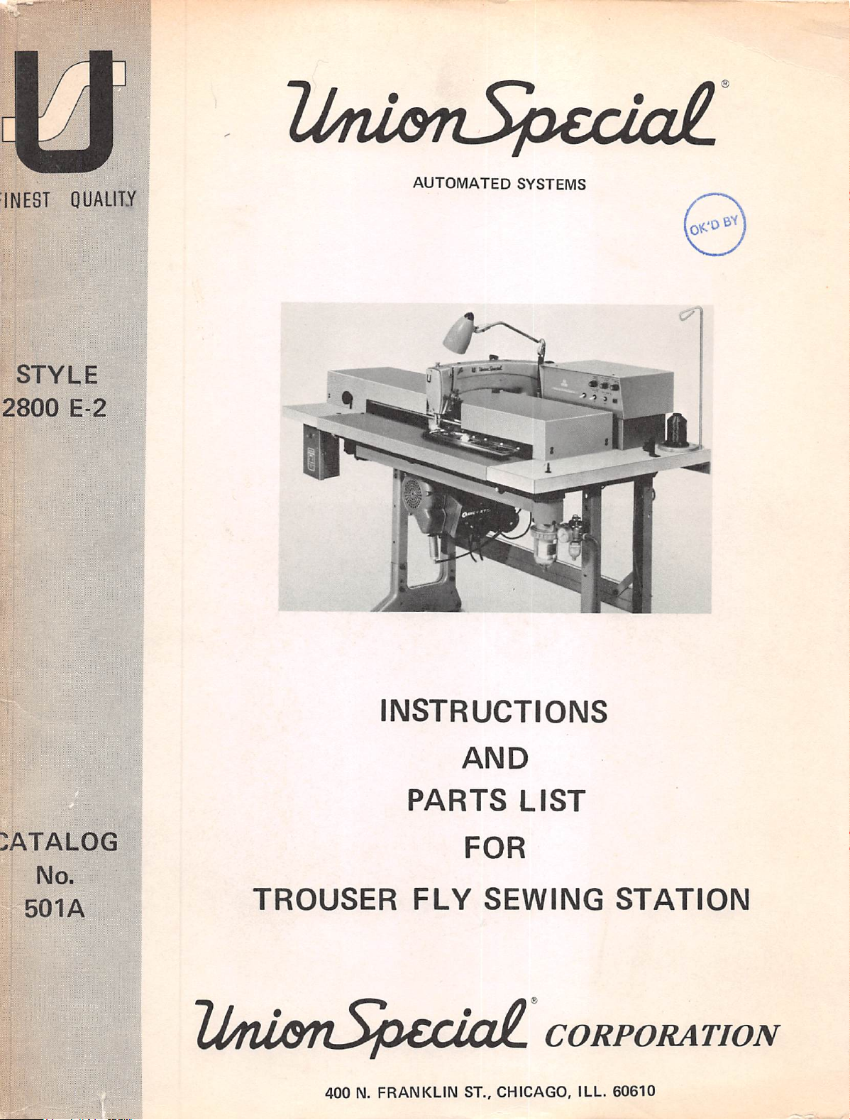
STYLE
2800
OUALITY
:
E-2
j
■
■
■ ■ ■
AUTOMATED
SYSTEMS
INSTRUCTIONS
AND
PARTS
FOR
No.
501A
1
Ij/rWQTlSpCCicdL
TROUSER
400
N.
FLY
FRANKLIN
SEWING
ST.,
CHICAGO,
LIST
STATION
CORPORATION
ILL.
60610
Page 2
This
technical
needed
and
so
The
functions
to
the
no
figure
electrical
malfunctions.
An
INDEX
shoot a particular
Station
nearly
matches
TROUBLESHOOTING
Each
STEP*
outlines
action
to
are
to
be
scribe
how
next
and
manual
has
do a particular
illustrations
numbers
in
OF
refer
the
be
taken.
to
how
are
never
or
references
portion
the
of
2800
the
E-2
MALFUNCTIONS
problem.
to
the
INDEX
the
problem.
section,
troubleshooting
entire
troubleshooting
taken,
and
the
Each
perform
to
bubble
that
interpret
FOREWORD
been
prepared
job
in
illustrated,
referenced
are
in
the
easy
in
the
needed.
to
text - The
TROUBLESHOOTING
Trouser
action.
the
Fly
Sewing
is
provided
To
use
the
manual
OF
MALFUNCTIONS
The
INDEX
and
gives
procedure
OF
the
page
is
presented
procedure.
arrangement
also
results
of
the
has a code
The
flow
lines
of
the
action
Station,
to
Each
bubbles
letter
STEP*
MALFUNCTIONS
leading
format.
follow
steps.
illustration
section
and
allow
you
to
troubleshoot
and
number
in a logic
"bubble"
in
which
out
just
taken.
The
No
provides
to
determine
to
refer
locate
on
which
sequence
of
the
the
chart
keys
it
of
each
fi^re
is
the
to
a
the
lists
each
flow
shows
to a series
bubble
procedures
numbers
always
information
"probable
the
malfunctioning
malfunction
the
procedure
flowchart,
provide
next
procedure
the
are
used
to
in
the
text
needed
failures"
to
causing
needed
Trouser
description
malfunctions
begins.
or
chart
contains a statement
the
order
of
illustrated
show
which
covered
"bubble
in
chart"
which
these
steps
action
information
this
format,
it
supports,
define
mal
such
to
trouble-
Fly
Sewing
that
most
in
the
which
of
an
actions
which
to
de
perform
SIMPLIFIED
TECHMQVES
'
EMPHASIZING
PERFORMANCE
570
Seventh
Developed
IT/
Avenue,
(NDUSmiAl
TCACKWe
CORPORATION
New
FOR
by
SYSTEMS
York,
New
York
CORPORATION
10018
Page 3
Catalog
INSTRUCTIONS
No.
FOR
501
A
LEFT
ADJUSTING
TROUSER
FIRST
AND
FLY
2800
EDITION
OPERATING
SEWING
E-2
STATION
Copyright
1973
By
May,
Union
Rights
1973
Special
Corporation
Chicago,
Resen/ed
Printed
in
in
III.
All
Countries
U.S.A.
Page 4
CONTENTS
Section
I
II
III
IV
GENERAL
A.
Operation
B.
Specifications
INFORMATION
INSTALLATION
A.
Inspection
B.
Check
Machine
C.
Check
Drive
Cable
D.
Check
Needle
Alignment
E.
Check
Oil
F.
Check
Rotation
G.
Installation
H.
Operation
I.
Stand-Up
OPERATOR
A.
Operating
B.
Machine
C.
Sequence
Timing
DESCRIPTION
A.
Switches
B.
Carriage
C.
Photocell
D.
Stop
E.
Slow
F.
Clamp
G.
Backtack
H.
Bobbin
I.
Pneumatic
J.
Unit
K.
Sewing
installation
INSTRUCTIONS
Hints
Care
of
Operation
Chart
Return
Position
Speed
Mechanical
Control
Start
Raise
Delay
Length
Winder
Controls
Head
Adjustments
AND
PRE-OPERATING
Head
of
Sewing
AND
ADJUSTMENT
Control
Adjustment
Control
Control
Systems
Head
Title
OF
INSTRUCTIONS
ELECTRICAL
CONTROLS
Page
1
1
2
3
3
3
3
3
3
4
4
5
6
9
9
9
9
11
13
13
14
14
15
15
15
15
16
16
16
20
V
VI
VII
VIII
GENERAL
A.
Cleaning
Lubrication
Replacement
PARTS
MAINTENANCE
LISTS
SCHEMATICS
TROUBLESHOOTING
25
25
25
25
27
40
43
Page 5
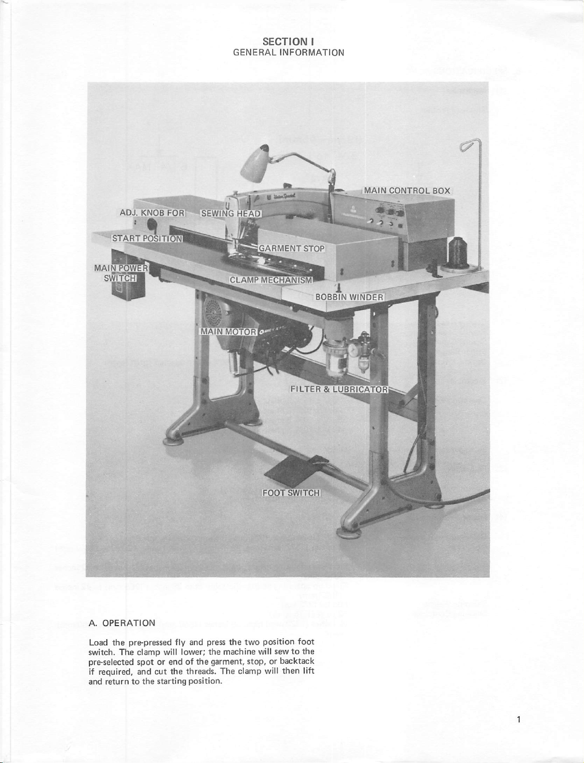
ADJ.
KNOB
F0"RT-^SEWING
GENERAL
HEAD
SECTION
INFORMATION
I
MAIN
CONTROL
BOX
START
MAINTOWER
SWITCH
POSITI
GARMENT
STOP
FILTER & LUBRICATOR
A.
OPERATION
Load
the
pre-pressed
switch.
pre-selected
if
and
The
clamp
spot
required,
return
and
to
the
fly
will
lower;
or
end
of
cut
the
threads.
starting
and
press
the
machine
the
garment,
The
position.
the
two
clamp
position
will
stop,
or
will
foot
sew
to
the
backtack
then
lift
Page 6
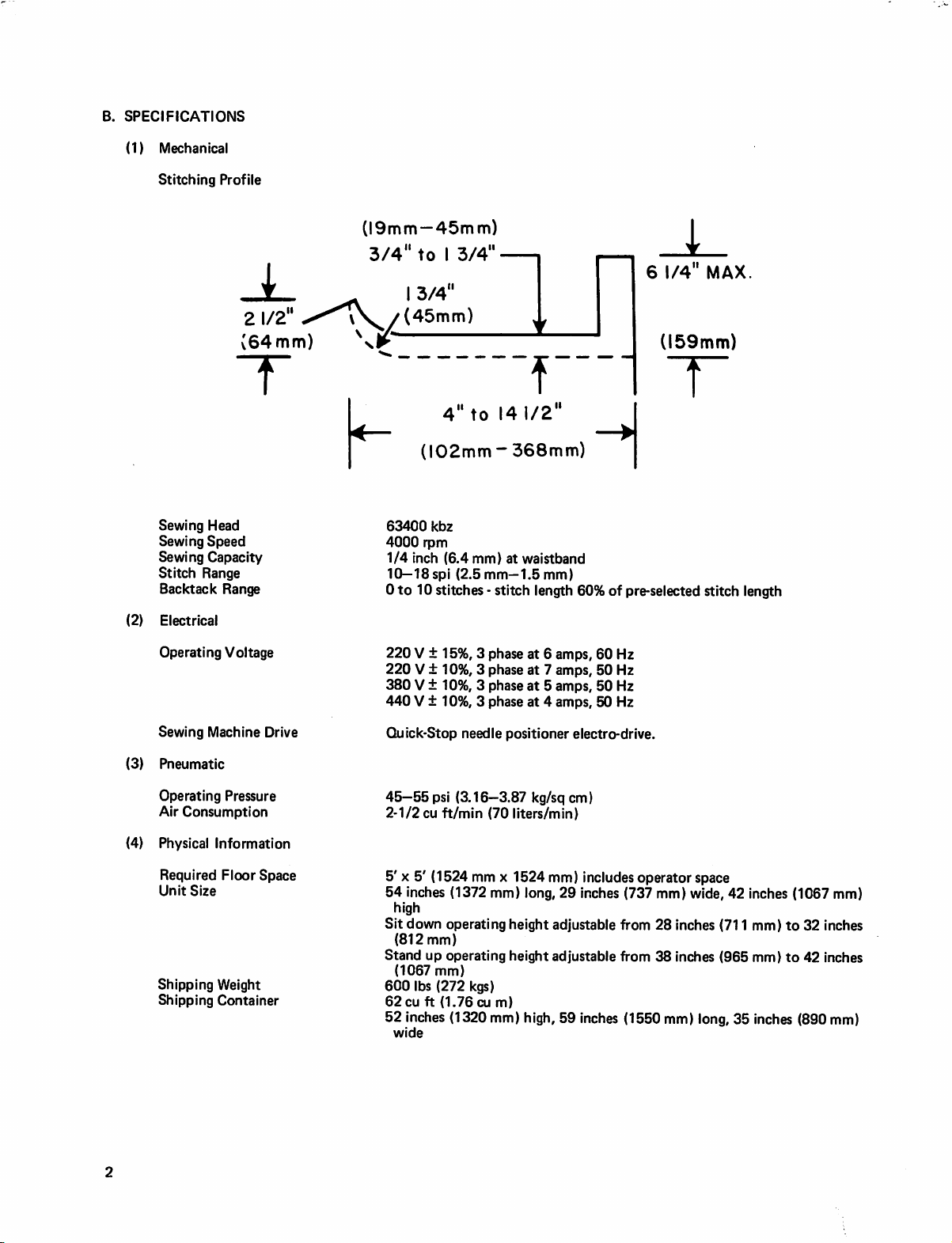
B.
SPECIFICATIONS
(1)
Mechanical
(2)
Stitching
Sewing
Sewing
Sewing
Stitch
Backtack
Electrical
Profile
Head
Speed
Capacity
Range
Range
2
1/2
(64mm)
(19mm—45mm)
3/4"to I 3/4"
3/4"
(45mm)
I
I
63400
4000
1/4
10—ISspi
0
4"to
(102mm
kbz
rpm
inch
(6.4
to
10
stitches - stitch
(2.5
f
l4i/2"
~
368mm)
mm)
at
waistband
mm—1.5
mm)
length
60%
i
6
1/4"
(159mm)
T
I
|
of
pre-selected
MAX
stitch
length
Sewing
(3)
Pneumatic
Operating
Air
(4)
Physical
Shipping
Shipping
Operating
Required
Unit
Voltage
Machine
Pressure
Consumption
Information
Floor
Size
Weight
Container
Drive
Space
220 V ±
220 V ±
380 V ±
440 V ±
Quick-Stop
45—55psi
2-1/2
5' X 5'
54
high
Sit
(812
Stand
(1067
600
62
52
wide
15%, 3 phase
10%, 3 phase
10%, 3 phase
10%, 3 phase
(3.16—3.87
cu
ft/min
(1524
inches
(1372
down
operating
mm)
up
operating
mm)
lbs
(272
cu
ft
(1.76
inches
(1320
needle
positioner
(70
liters/min)
mm x 1524
mm)
long,
height
height
kgs)
cu
m)
mm)
high,
at 6 amps,
at 7 amps,
at 5 amps,
at 4 amps,
kg/sq
60
50
50
50
electro-drive.
cm)
mm)
includes
29
inches
adjustable
adjustable
59
inches
Hz
Hz
Hz
Hz
operator
(737
mm)
from
28
from
38
(1550
space
wide,
inches
inches
mm)
long,
42
(711
(965
35
inches
(1067
mm)
to
mm)
to
inches
(890
32
inches
42
inches
mm)
mm)
Page 7
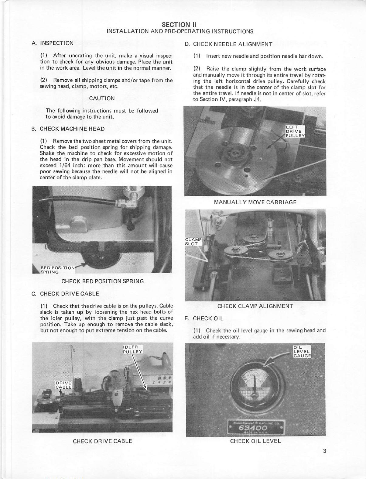
A.
INSPECTION
11)
tion
in
(2)
sewing
B.
CHECK
(1)
Check
Shake
the
exceed
poor
center
After
to
check
the
work
Remove
head,
The
following
to
avoid
Remove
the
the
head
1/64
sewing
of
uncrating
for
area.
all
shipping
clamp,
damage
MACHINE
the
bed
position
machine
in
the
drip
inch:
because
the
clamp
INSTALLATION
unit,
any
Level
obvious
the
damage.
unit
clamps
motors,
CAUTION
instructions
to
HEAD
two
the
unit.
sheet
etc.
must
metal
spring
to
check
for
pan
base.
more
than
this
the
needle
plate.
AND
make a visual
Place
the
in
the
normal
and/or
be
covers
for
shipping
excessive
Movement
amount
will
not
manner.
tape
from
followed
from
the
damage.
motion
should
will
be
aligned
SECTION
PRE-OPERATING
inspec
unit
the
unit.
of
not
cause
in
D.
II
CHECK
(1)
(2)
an.d
manually
ing
the
that
the
the
entire
to
Section
INSTRUCTIONS
NEEDLE
Insert
new
Raise
the
move
left
horizontal
needle
travel.
IV,
paragraph
ALIGNMENT
needle
clamp
slightly
it
through
is
in
the
If
needle
and
position
drive
center
is
not
J4.
needle
from
the
its
entire
pulley.
Carefully
of
the
in
center
bar
work
travel
by
clamp
of
slot,
down.
surface
rotat
check
slot
for
refer
E.
CHECK
MANUALLY
CHECK
OIL
CLAMP
MOVE
CARR
I
ALIGNMENT
AGE
CHECK
DRIVE
CABLE
CHECK
OIL
LEVEL
Page 8
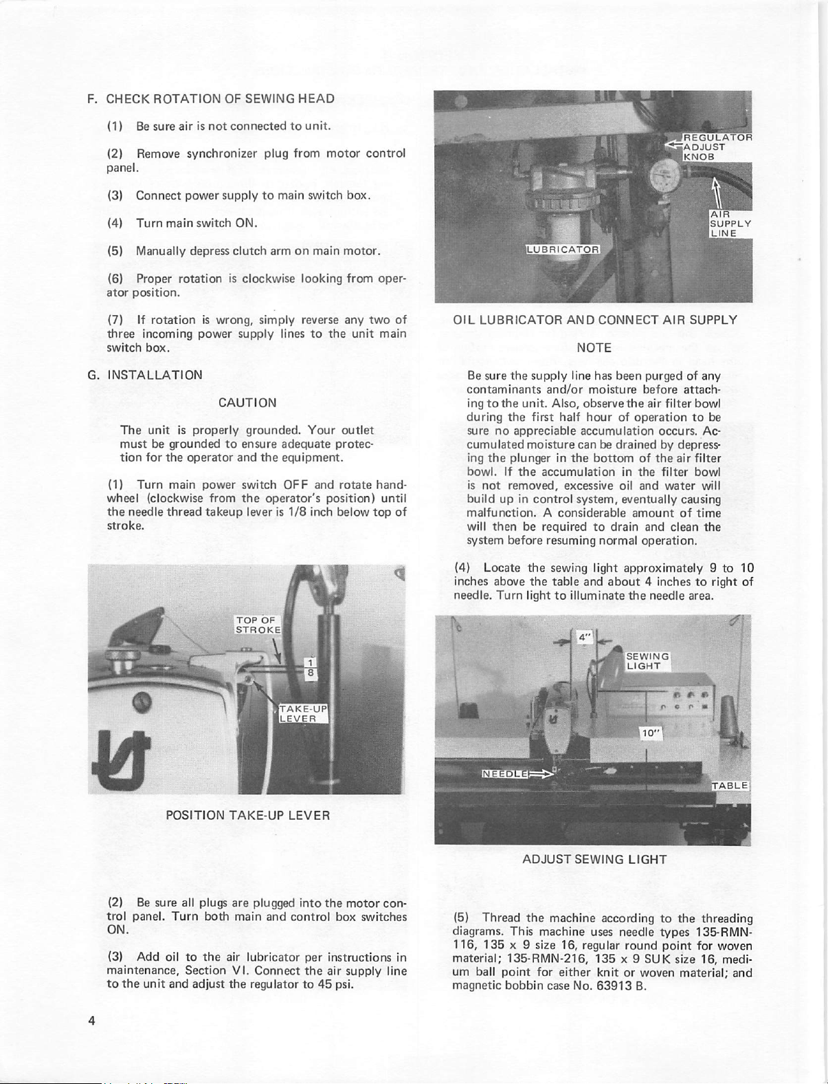
F.
CHECK
(1)
(2)
panel.
(3)
(4)
(5)
(6)
atCH-
(7)
three
switch
G.
INSTALLATION
The
must
tion
(1)
wheel
the
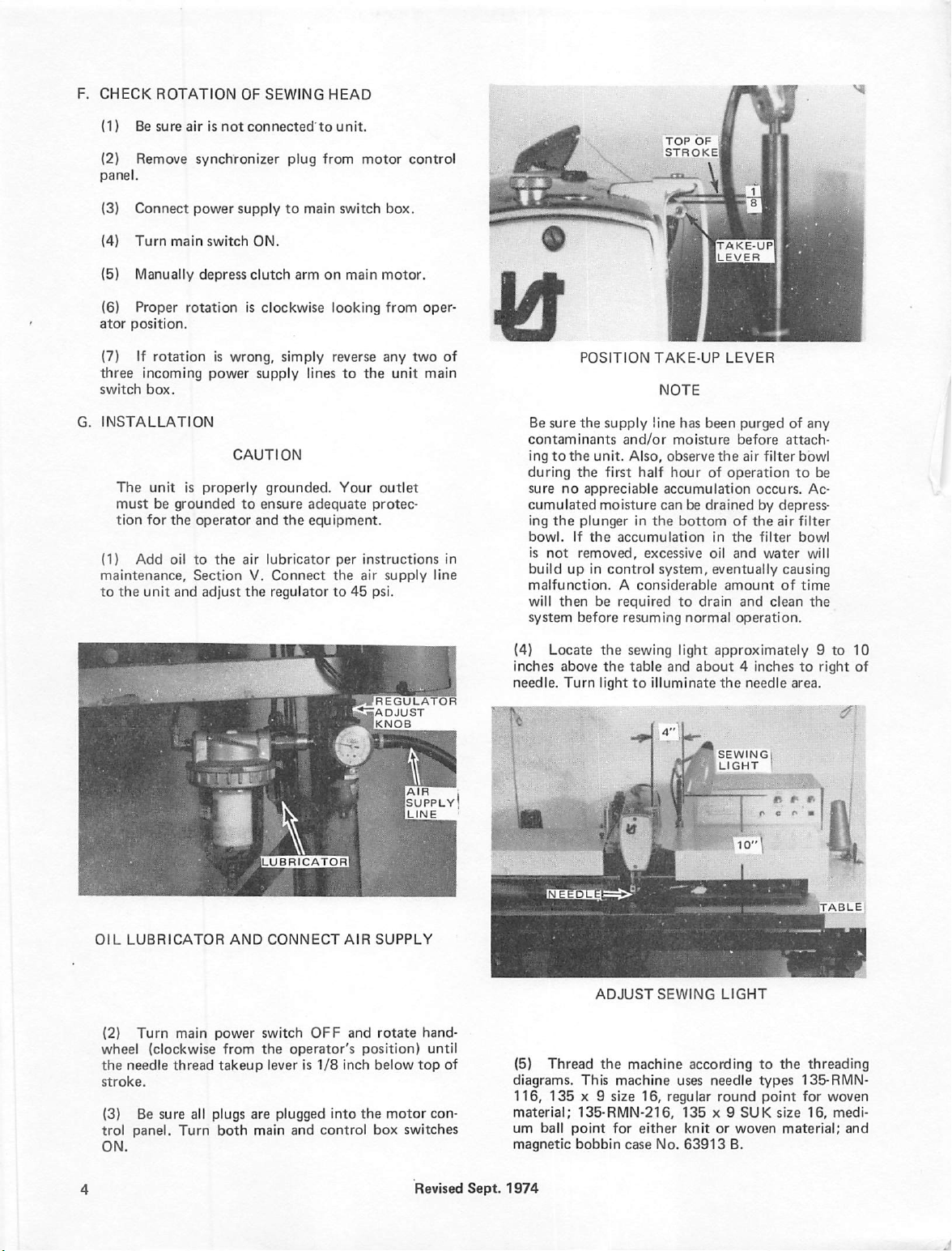
stroke.
ROTATION
Be
sure
Remove
Connect
Turn
main
Manually
Proper
position.
If
rotation
incoming
box.
unit
be
grounded
for
the
Turn
main
(clockwise
needle
thread
OF
SEWING
air
is
not
connected
synchronizer
power
supply
switch
ON.
depress
rotation
is
operator
clutch
is
clockwise
is
wrong,
power
supply
CAUTION
properly
to
ensure
and
power
switch
from
the
takeup
grounded.
lever
HEAD
to
unit.
plug
from
to
main
switch
arm
on
main
looking
simply
reverse
lines
to
Your
adequate
the
equipment.
OFF
and
operator's
is
1/8
inch
motor
control
box.
motor.
from
oper-
any
two
the
unit
main
outlet
protec
rotate
hand-
position)
below
until
top
of
of
Ilubricator!
OIL
LUBRICATOR
Be
sure
the
contaminants
ing
to
the
unit.
during
the
sure
no
appreciable
cumulated
ing
the
plunger
bowl.
If
the
is
not
build
malfunction. A considerable
will
system
removed,
up
in
then
before
be
AND
NOTE
supply
line
and/or
Also,
first
half
moisture
control
can
in
the
accumulation
excessive
system,
required
resuming
moisture
observe
hour
accumulation
to
CONNECT
has
been
the
of
operation
be
drained
bottom
in
oil
eventually
amount
drain
normal
IREGULATOR
EADJUST
Iknob
AIR
SUPPLY
purged
before
air
filter
of
attach
to
occurs.
by
depress
of
the
air
filter
the
filter
and
water
causing
of
and
clean
operation.
AIR
SUPPLY
LINE
any
bowl
be
Ac
bowl
will
time
the
POSITION
(2)
Be
sure
all
trol
panel.
Add
unit
Turn
oil
to
Section
and
ON.
(3)
maintenance.
to
the
TAKE-UP
plugs
both
the
air
adjust
the
take-up
LEVER
LEVER
are
plugged
main
and
control
lubricator
VI.
Connect
regulator
into
the
motor
box
switches
per
instructions
the
air
45
supply
psi.
to
con
line
in
(4)
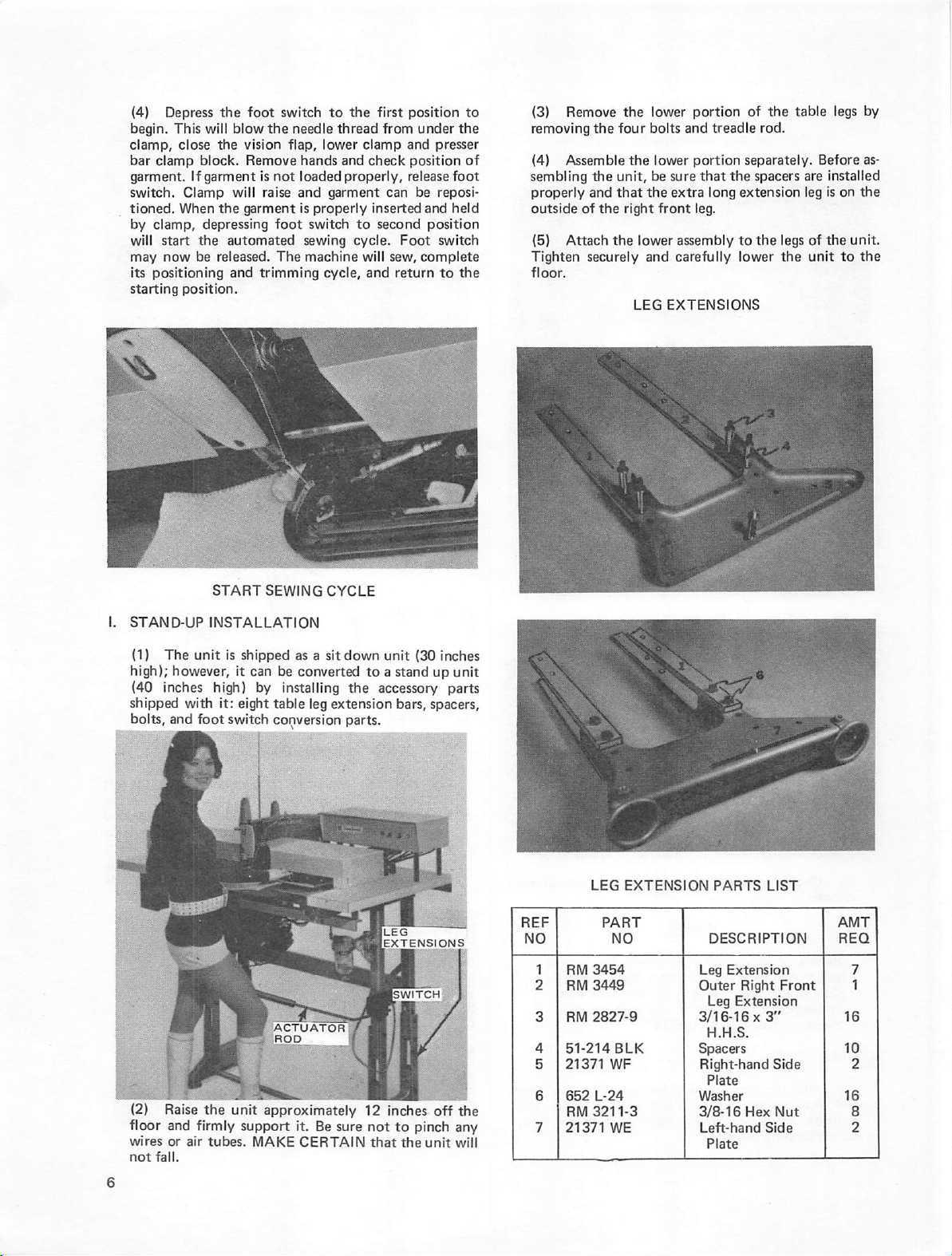
Locate
inches
above
needle.
Turn
(5)
Thread
diagrams.
116,
material;
um
magnetic
This
135 X 9
135-RMN-216,
ball
point
bobbin
the
sewing
the
light
ADJUST
the
machine
machine
size
for
case
light
table
and
about 4 inches
to
illuminate ti^e
SEWING
according
uses
16,
regular
135 x 9
either
knit
No.
63913
approximately 9 to
to
right
needle
area.
SEWING
LIGHT
LIGHT
to
the
threading
needle
types
round
SUK
or
woven
135-RMN-
point
for
size
16,
material;
woven
medi
B.
10
of
and
Page 9
F.
CHECK
(1)
Be
(2)
Remove
panel.
(3)
Connect
(4)
Turn
(5)
Manually
(6)
Proper
ator
position.
(7)
If
three
incoming
switch
box.
G.
INSTALLATION
The
must
tion
for
(1)
Add
maintenance,
to
the
unit
ROTATION
sure
air
is
synchronizer
power
main
switch
depress
rotation
rotation
is
power
unit
is
properly
be
grounded
the
operator
oil
to
the
Section
and
adjust
OF
SEWING
not
connected'to
plug
supply
to
ON.
clutch
is
clockwise
wrong,
simply
supply
CAUTION
grounded.
to
ensure
and
the
air
lubricator
V.
Connect
the
regulator
HEAD
unit.
from
main
switch
arm
on
main
looking
reverse
lines
to
Your
adequate
equipment.
per
the
to
motor
control
box.
motor.
from
oper
any
two
the
unit
main
outlet
protec
instructions
air
supply
45
psi.
of
in
line
fa
POSITION
Be
sure
the
supply
contaminants
ing
to
the
during
sure
no
cumulated
ing
the
bowl.
If
is
not
build
up
malfunction. A considerable
will
then
system
and/or
unit.
the
first
appreciable
moisture
plunger
the
accumulation
removed,
in
control
be
required
before
resuming
TOP
STROKE!
TAKE-UP
NOTE
line
has
moisture
Also,
observe
half
hour
accumulation
can
be
in
the
bottom
excessive
system,
to
normal
OF
I
tTAKE-UPl
LEVER
LEVER
been
purged
before
attach
the
air
filter
of
operation
drained
drain
occurs.
by
depress
of
the
air
in
the
oil
filter
and
water
eventually
amount
causing
of
and
clean
operation.
of
any
bowl
to
be
Ac
filter
bowl
will
time
the
OIL
<2)
wheel
the
stroke.
(3)
trol
ON.
LUBRICATOR
Turn
main
(clockwise
needle
thread
Be
sure
panel.
Turn
all
AND
power
from
takeup
plugs
are
both
main
LUBRICATOR
CONNECT
switch
the
operator's
lever
is
plugged
and
AIR
OFF
and
1/8
inch
into
control
W^REGULATOR
ADJUST
KNOB
SUPPLY
rotate
below
motor
box
switches
hand-
top
position)
the
until
of
con
(4)
Locate
inches
above
needle.
(5)
diagrams.
116,
material;
um
magnetic
Turn
Thread
135 X 9
135-RMN-216,
ball
point
bobbin
the
the
light
ADJUST
the
This
sewing
table
to
illuminate
SEWING
machine
machine
size
16,
for
either
case
No.
light
approximately 9 to
and
about 4 inches
the
needle
SEWING
LIGHT
LIGHT
according
uses
needle
regular
round
135 x 9
knit
or
63913
SUK
woven
B.
to
area.
to
the
types
135-RMN-
point
for
size
material;
10
right
of
threading
woven
16,
medi
and
Revised
Sept.
1974
Page 10
Do
not
use
any
listed
without
representative.
CAUTION
other
needle
consulting
your
except
Union
Special
1
those
(6)
Check
systems.
MACHINE
MACHINE
the
r-.
THREADING
Uni^n^ujuoji
THREADING
settings
of
DIAGRAM
DIAGRAM
the
photocells
and
control
MACHINE
(2)
Place
with
zipper
material
piate.
The
the
edge
MATERIAL
(3)
Hold
of
the
clamp,
finger
of
clamp.
the
ly
right
of
With
front
by
holding
hand
clamp.
READY
the
pre-pressed
facing
down.
Is
just
covering
waistband
guide,
which
POSITIONING
the
bottom
and
the
the
right
the
to
of
the
the
the
thumb
left
right.
edge
FOR
Be
the
end
of
is
set
to
STARTING
POINT
MATERIAL
of
fly
top
of
hand
in
holding
clamp,
hand
Keep
OPERATION
left
fly
under
sure
that
the
needle
hole
in
the
fly
should
margin
requirements.
THROAT
PLATE
with
left
hand
the
fly
with
the
clearance
the
stretch
stationary
fingers
material
the
material
and
clear
of
the
clamp
edge
of
the
the
throat
be
against
to
the
left
the
middle
cut
in
the
outside
slight
moving
the
underside
NOTE
Before
stitch
Operation.
in
ments
H.
OPERATION
(1)
will
position.
for
operating
length
and
Stitch
Section
When
be
positioning
are
at
The
IV.
found
the
the
extreme
vision
unit
the
unit
stop
position,
length
Stop
in
Section
is
ready
right
flap
work.
to
check
read
adjustment
position
end
is
open
IV.
for
control
operation,
of
for
for
proper
Section
is
found
adjust
its
stroke
better
II,
the
clamp
in
raised
visibility
HOLD
MATERIAL
CLAMPING
MATERIAL
STRETCH
SLIGHTLY
Page 11
(4)
Depress
begin.
This
clamp,
bar
close
clamp
garment.
switch.
tioned.
by
will
may
its
starting
Clamp
When
clamp,
start
now
positioning
position.
the
foot
will
blow
the
vision
block.
Remove
If
garment
will
the
garment
depressing
the
automated
be
released.
and
switch
the
needle
flap,
hands
Is
not
loaded
raise
and
is
properly
foot
switch
sewing
The
machine
trimming
to
the
thread
lower
clamp
and
check
properly,
garment
to
cycle.
will
cycle,
and
first
position
from
under
and
position
release
can
be
inserted
second
and
position
Foot
sew,
complete
return
to
the
presser
of
foot
reposi-
held
switch
to
the
(3)
Remove
removing
(4)
Assemble
sembling
properly
outside
(5)
Tighten
floor.
the
and
of
Attach
securely
the
the
the
the
lower
four
bolts
the
lower
unit,
be
that
the
right
lower
and
LEG
portion
and
portion
sure
that
extra
front
leg.
assembly
carefully
EXTENSIONS
of
treadle
separately.
the
spacers
long
extension
to
the
lower
the
rod.
table
are
leg
legs
of
the
legs
Before
installed
is
on
the
unit.
unit
to
by
as
the
the
I.
STAND-UP
(1)
high);
(40
shipped
bolts,
(2)
floor
wires
not
The
unit
however,
inches
with
and
foot
Raise
the
and
firmly
or
air
fall.
START
INSTALLATION
high)
SEWING
is
shipped
it
can
be
by
it:
switch
unit
installing
eight
table
conversion
approximately
support
tubes.
MAKE
CYCLE
as a sit
down
converted
the
leg
extension
parts.
12
it.
Be
sure
CERTAIN
unit
(30
to a stand
up
accessory
bars,
spacers,
inches
off
not
to
pinch
that
the
unit
inches
unit
parts
the
any
will
LEG
RM
2827-9
51-214
21371
652
L-24
RM
3211-3
21371
EXTENSION
PART
NO
BLK
WF
WE
PARTS
DESCRIPTION
Leg
Outer
Leg
3/16-16 X 3"
H.H.S.
LIST
Extension
Right
Extension
Spacers
Right-hand
Plate
Washer
3/8-16
Left-hand
Plate
Side
Hex
Side
Front
Nut
Page 12
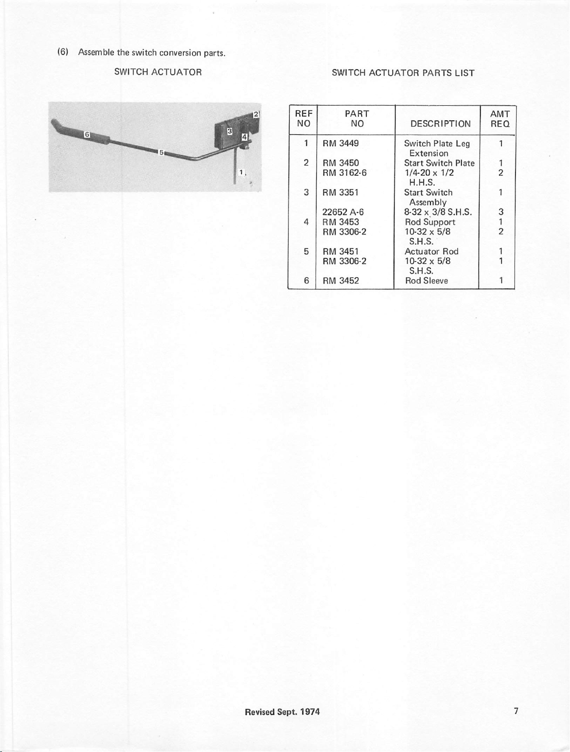
(6)
Assemble
the
switch
conversion
parts.
SWITCH
ACTUATOR
EF
JO
1 RM
2 RM
RM
3 RM
22652
4 RM
RM
5 RM
RM
6 RM
SWITCH
PART
NO
3449
3450
3162-6
3351
A-6
3453
3306-2
3451
3306-2
3452
ACTUATOR
PARTS
DESCRIPTION
Switch
Plate
Extension
Start
Switch
1/4-20 X 1/2
H.H.S.
Start
Switch
Assembly
8-32 X 3/8
Rod
Support
10-32 X 5/8
S.H.S.
Actuator
10-32 X 5/8
S.H.S.
Rod
Rod
Sleeve
LIST
Leg
Plate
S.H.S.
Page 13
(6)
Assemble
the
switch
conversion
parts.
SWITCH
ACTUATOR
SWITCH
EF
JO
1 RM
2 RM
RM
3 RM3351
22652
4 RM3453
RM
5 RM
RM
6 RM
PART
NO
3449
3450
3162-6
A-6
3306-2
3451
3306-2
3452
ACTUATOR
PARTS
DESCRIPTION
Switch
Start
Start
Plate
Extension
Switch
1/4-20 X 1/2
H.H.S.
Switch
Assembly
8-32
x,3/8S.H.S.
Rod
Support
10-32x5/8
S.H.S.
Actuator
Rod
10-32 x 5/8
S.H.S.
Rod
Sleeve
LIST
Leg
Plate
Revised
Sept.
1974
Page 14
A.
OPERATING
(1)
fly
(2)
(3)
cycle
(4)
needle;
(5)
check
8.
MACHINE
(1)
ating;
level
If
either
(2)
moved,
Section
C.
SEQUENCE
Be
sure a slight
and
held
until
Do
not
pull
Do
not
assist
is
completed.
If
machine
check
for
If
bobbin
threading
CARE
Every
day:
check
oil
in
air
lubricator
oil
level
Mid-day
blow
lint
IV).
OF
HINTS
clamp
on
garment
the
skips
proper
thread
of
bobbin
replace
sight
mounted
is
low,
and
end
from
OPERATION
amount
of
contacts
once
material
stitches
in
or
threading.
does
not
case.
needle
gauge
first
on
sewing
on
notify
the
of
day:
hook
area
OPERATOR
stretch
it.
clamp
is
any
way
breaks
thread,
cut
at
end
thing
head;
right
front
mechanic
with
bobbin
with
air
SECTION
is
applied
down.
until
after
check
of
cycle,
before
oper
check
table
at
once.
case
hose
(see
INSTRUCTIONS
to
oil
leg..
re
III
c.
Vision flap
d.
90
The
and
volts
The
dc,
foot
closing
occurs.
to
(3)
ing
following
a. A time
energized,
speed
mode
operation
held
Solenoid A de-energizes
pletely
is
energized,
cylinder
then
preventing
mode.
b.
The
through
c.
The
so
independent
d.
The
released,
e.
After
which
run
at
high
closes
voltage
to
preparing
switch
is
the
second
delay
control
machine
machine
the
control
that
foot
the
supplying
starts
main
circuit
the
voltages
of
the
switch
shutting
time
engages
speed.
as
the
clamp
then
motor
foot
can
when
off
delay
air
the
solenoid E is
electric
to
feed.
depressed
position
delays
from
sewing
circuit.
locks
to
solenoids E and D are
switch.
be
released
the
the
air
is
timed
to
the
clutch.
energized.
clutch
further,
switch
solenoid B being
going
in
the
unit
into
at
foot
switch
wiper.
out,
electro-drive
The
machine
is
increased
engag
FS2.
The
into
high
low
speed
automatic
this
point.
is
com
solenoid
clutch
will
B
(1)
Refer
to
position
following
mately
the
clutch
backtack
cycle.
solenoid
is
the
vision flap
(2)
foot
FS1.
energized.
closed
chine
with
conditions
a.
The
10
b.
Solenoid A is
thread
c.
Solenoid B is
cylinder
d.
Solenoid C is
lever
e.
Solenoid D is
supplies
up),
and
f.
Solenoid E is
vision
flap
The
operator
switch
The
following
a.
Air
b.
Clamp
clamp
to
operate.
volts
wiper
the
open.
to
When
timing
chart.
both
main
are
electric
clutch
dc.
system.
retracted
cylinder
de-energized.
air
to
presser
cylinder,
loads
engage
and
occurs.
wiper
blows
and
presser
the
interlock
When
the
unit
and
control
in
effect.
is
de-energized,
de-energized,
and
the
de-energized,
controlling
switches
energized
shutting
with
unit
not
shutting
the
This
the
clamp
lift
foot
cylinder
de-energized,
which
the
close
as
solenoid A is
lifter
switch
(presserfoot
shutting
is
retracted
material
the
first
bar
drop
lever
moves,
opens,
and
as
is
in
the
rest
ON,
the
with
approxi
off
air
electro-drive
sewing.
off
air
reverse
normally
cylinder
depresses
position
energized.
solenoid D is
the
preparing
(clamp
is
off
air
to
keep
switch
normally
feed
open
up).
the
the
ma
to
to
to
(4)
When
the
clamp
the
photocell
to
the
waistband, a time
machine
stop
this
clutch
operation
tion
de-energized,
flap.
10
for
before
switch
lever
next
clamp
to
will
position
delay,
the
a.
Solenoid B is
to
disengage
to
low
b.
Needle
c.
After a pre-set
of
position
allowing
d.
Solenoid E is
e.
Electric
volts
dc,
preparing
f.
The
clamp
the
clamp
When
on
the
and
closes,
After
return
start
clamp
cycle.
position.
the
g.
sewing
h.
the
continue
time
following
speed.
positioning
clutch
to
starts
the
sewing
preparing
the
motor
moves
the
machine
delay
occurs
to
run
delay
is
completed.
occurs.
de-energized,
and
bring
machine
and
time
delay
and
trimming
clamp
to
de-energized,
voltage
for
clamp
return
and
its
return
clamp
head
return
is
activated,
delay
the
raises,
is
the
raise
clamp
pants
panel,
light
at
the
before
at
high
speed
At
causing
from
trimming
to
ensure
cycles,
raise.
opening
decreases
return.
begins,
providing
presser
cycle.
the
clamp
engaged
control
circuit
delay
times
returning
exposing
end
of
the
stopping.
cycles
solenoid D is
from
bar
by
The
until
this
the
end
the
quick
high
speed
occur.
comple
up
vision
90
time
to
retract
interlock
the
lifter
for
the
out,
the
the
clamp
of
to
Page 15
i.
When
a
stud
on
return
return
(5)
loading
(6)
backtack
sired
backtack
operations
is
de-energized,
cycle
sequence
the
limit
motor.
The
unit
of
the
The
above
switch
at
the
switch
ends,
will
switch,
waistband
is
identical
main
the
clamp
left-hand
is
now
next
drive
which
in tiie
panel.
sequence
in
the
NO
end
at
the
YES
to
the
paragraph
motor
decelerates
be
as
follows.
returns
shuts
of
to
pulley
off
rest
position,
operation
position.
of
the
position.
point
4a.
When
the
start
engages
power
to
ready
is
given
If
backtack
garment,
The
sequence
at
which
solenoid
high
speed
to
slow
speed.
position,
the
clamp
the
clamp
for
the
with
the
is
de
place
the
of
sewing
The
a.
The
b.
air
to
the
arm
on
clamp
in
c.
tack
solenoid D to
d.
off,
causing
drive
to
backtack
Backtack
backtack
the
transmission
the
reverse
The
backtack
Air
supplied
the
return
timer
solenoid C is
cylinder.
direction.
timer
de-energize.
to
the
reversing
to
the
forward
is
started.
energized,
This
causes
drive
to
times
backtack
arm
on
position.
supplying
the
move,
driving
out,
causing
cylinder
the
transmission
reversing
the
back
is
shut
B
(7)
The
rest
of
the
in
the
graph
4b.
operation
non-backtack
sequence,
sequence
beginning
is
described
with
para
10
Page 16
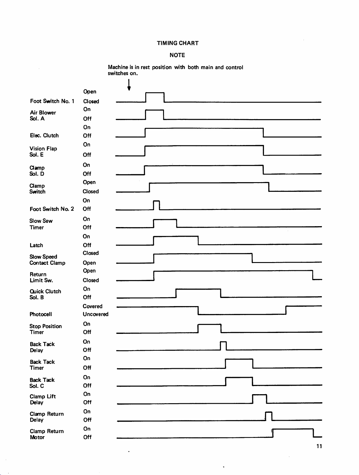
TIMING
NOTE
CHART
Foot
Switch
Air
Blower
Sol.
A
Elec.
Clutch
Vision
Flap
Sol.
E
Clamp
Sol.
D
Clamp
Switch
Foot
Switch
Slow
Sew
Timer
Latch
Slow
Speed
Contact
Return
Limit
Sw.
Quick
Clutch
Sol.
8
Photocell
Stop
Position
Timer
Back
Tack
Delay
Back
Tack
Timer
Back
Tack
Sol.C
Clamp
Lift
Delay
Clamp
Return
Delay
Clamp
Return
Motor
No.
Clamp
No.
1
2
Open
Closed
On
Off
On
Off
On
Off
On
Off
Open
Closed
On
Off
On
Off
On
Off
Closed
Open
Open
Closed
On
Off
Covered
Uncovered
On
Off
On
Off
On
Off
On
Off
On
Off
On
Off
On
Off
Machine
switches
I
Is
on.
in
rest
position
n
with
both
J
main
and
L
n
control
J
n
L
n
11
Page 17
A.
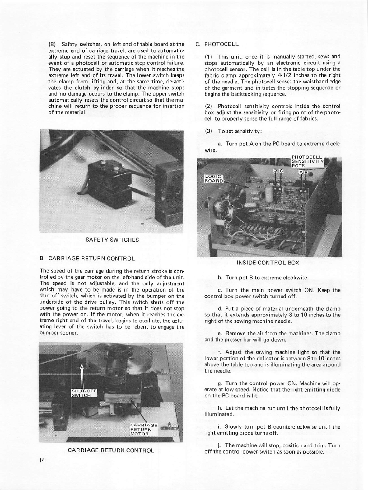
SWITCHES
(1)
ranges;
2800
E-2
is
DESCRIPTION
available
in
the
AND
following
SECTION
ADJUSTMENT
voltage
IV
OF
ELECTRICAL
CONTROLS
220 V ±
220 V ±
380 V ±
440 V ±
12)
Main
power
table,
controls
positioner,
box.
(3)
controls
drive,
chine
trim
MAIN
Control
all
functions
needle
light.
15%, 3 phase, 6 amps,
10%, 3 phase, 7 amps,
10%, 3 phase, 5 amps,
10%, 3 phase, 4 amps,
switch,
the
cycle,
POWER
power
positioning,
under
power
to
machine
SWITCH
switch,
of
the
trim
left-hand
the
electro-drive,
light,
BOX
on
face
unit
except
cycle,
60
Hz
50
Hz
50
Hz
50
Hz
and
POWER
SWITCH
of
and
side
of
needle
the
control
ON/OFF
control
the
electro-
box,
sewing
the
ma
(5)
Threading
box,
is
used
better
switch
that
(6)
selector
stitch a left
end.
tion,
end
exposed
should
the
next
position,
Is
clamp
garment
the
inactivated.
Backtack
left
of
the
switch
If
the
the
unit
of
seam.
control
fly
backtack
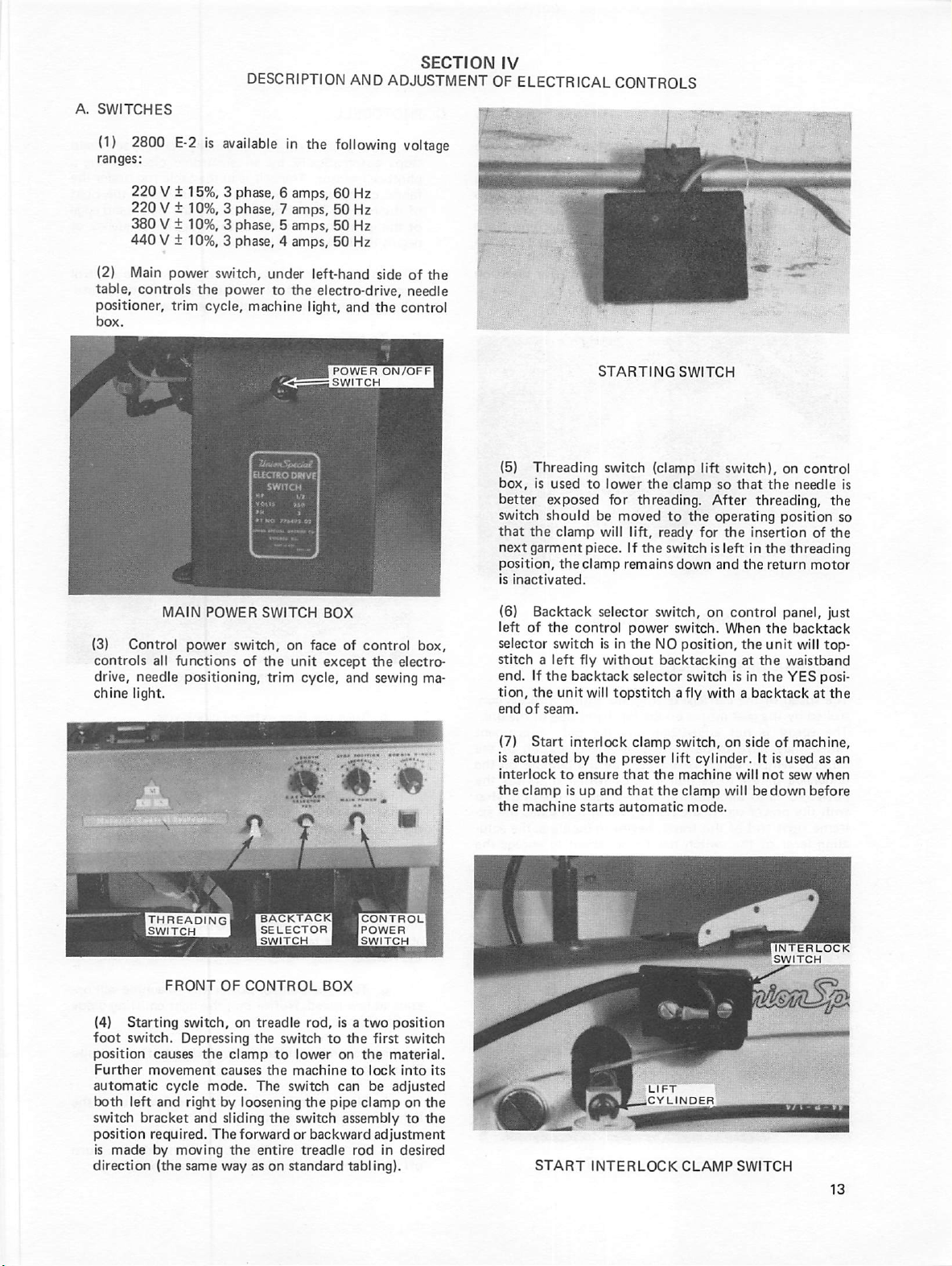
STARTING
switch
to
lower
for
threading.
be
moved
will
lift,
piece.
If
the
clamp
remains
selector
power
is
in
the
without
selector
will
topstitch a fly
SWITCH
(clamp
the
lift
clamp
switch),
so
After
to
the
operating
ready
for
switch
switch,
NO
the
is
left
down
and
on
switch.
When
position,
backtacking
switch
with a backtack
on
that
the
threading,
position
insertion
in
the
threading
the
return
control
is
the
at
the
in
the
panel,
the
backtack
unit
waistband
YES
control
needle
is
the
so
of
the
motor
just
will
top-
posi
at
the
THREADING
SWITCH
FRONT
(4)
Starting
foot
switch.
position
Further
automatic
both
switch
position
is
direction
left
bracket
made
causes
movement
cycle
and
required.
by
(the
OF
CONTROL
switch,
Depressing
moving
same
the
causes
mode.
right
by
and
sliding
The
way
on
clamp
loosening
forward
the
treadle
the
switch
to
lower
the
machine
The
switch
the
switch
or
entire
as
treadle
on
standard
BOX
rod,
is a two
to
the
on
to
can
the
pipe
assembly
backward
rod
tabling).
CONTROL
POWER
SWITCH
position
first
switch
the
material.
lock
into
be
adjusted
clamp
on
to
adjustment
In
desired
its
the
the
(7)
Start
is
actuated
interlock
the
clamp
the
machine
START
interlock
by
the
presser
to
ensure
that
Is
up
and
that
starts
automatic
INTERLOCK
clamp
lift
the
the
LIFT
CYLINDER
switch,
on
cylinder.
machine
clamp
will
mode.
CLAMP
side
It
will
not
bedown
SWITCH
of
machine,
is
used
sew
before
INTERLOCK
SWITCH
as
when
an
Page 18
(8)
Safety
switches,
extreme
ally
event
They
extreme
the
vates
and
automatically
chine
of
end
stop
clamp
no
the
of
and
reset
of a photocell
are
actuated
left
end
from
the
clutch
damage
resets
will
return
material.
on
carriage
lifting
occurs
travel,
the
sequence
or
automatic
by
the
of
its
travel.
and,
cylinder
to
the
control
to
the
proper
left
end
of
are
of
carriage
The
at
the
so
that
the
clamp.
circuit
sequence
table
used
the
stop
when
lower
same
the
The
board
to
automatic
machine
control
so
failure.
it
reaches
switch
time,
de-acti
machine
upper
that
the
for
insertion
at
the
in
the
the
keeps
stops
switch
ma
C.
PHOTOCELL
(1)
stops
photocell
fabric
of
the
of
the
begins
(2)
box
cell
to
(3)
This
unit,
once
automatically
sensor.
clamp
needle.
garment
the
Photocell
adjust
properly
To
set
a.
Turn
The
approximately
The
photocell
and
backtacking
sensitivity
the
sensitivity
sense
sensitivity:
pot A on
it
is
manually
by
an
electronic
cell
is
in
4-1/2
initiates
senses
the
sequence.
controls
or
firing
the
full
the
PC
range
board
started,
the
table
inches
the
stopping
inside
point
of
fabrics.
to
PHOTOCELL
SENSITIVITY
POTS
sews
circuit
waistband
extreme
using
top
under
to
the
sequence
the
control
of
the
photo
clock-
right
edge
and
a
the
or
B.
CARRIAGE
The
speed
trolled
by
The
which
shut-off
underside
power
witii
treme
ating
bumper
the
speed
may
switch,
going
the
power
right
lever
sooner.
of
is
have
of
to
end
of
SHUT-OFF
SWITCH
SAFETY
RETURN
the
carriage
gear
motor
not
adjustable,
to
be
which
the
drive
the
return
on.
If
of
the
the
switch
SWITCHES
CONTROL
during
on
the
made
is
is
activated
pulley.
motor
the
motor,
travel,
begins
has
to
the
return
left-hand
and
the
only
in
the
operation
by
the
This
switch
so
that
when
it
to
oscillate,
be
rebent
CARRIAGE
RETURN
MOTOR
stroke
side
of
the
adjustment
bumper
shuts
it
does
reaches
the
to
engage
is
of
on
off
not
the
con
unit.
the
the
the
stop
ex
actu
the
b.
Turn
c.
Turn
control
so
right
and
lower
above
the
erate
on
illuminated.
light
box
d.
Put a piece
that
it
of
the
e.
Remove
the
presser
f.
Adjust
portion
the
needle.
g.
Turn
at
low
the
PC
h.
Let
i.
Slowly
emitting
INSIDE
pot B to
the
power
extends
sewing
the
bar
the
of
the
table
top
the
control
speed.
board
is
the
machine
turn
diode
CONTROL
extreme
main
power
switch
of
material
approximately 8 to
machine
air
from
will
go
sewing
deflector
and
is
Notice
lit.
run
pot B counterclockwise
turns
BOX
clockwise.
switch
turned
underneath
needle.
the
down.
machine
is
between 8 to
illuminating
power
that
the
until
off.
ON.
off.
10
machines.
light
the
ON.
Machine
light
emitting
the
photocell
inches
Keep
the
The
so
that
10
area
around
will
until
the
clamp
to
the
clamp
the
inches
op
diode
is
fully
the
j.
CARRIAGE
RETURN
CONTROL
off
the
control
The
machine
power
will
stop,
switch
position
as
soon
and
as
possible.
trim.
Turn
Page 19
(8)
Safety
switches,
extreme
ally
event
They
extreme
the
vates
and
automatically
chine
of
end
of
stop
and
reset
of a photocell
are
actuated
left
end
clamp
from
the
clutch
no
damage
resets
will
return
the
material.
on
carriage
of
lifting
occurs
to
travel,
the
sequence
or
automatic
by
the
its
travel.
and,
cylinder
to
the
control
the
proper
left
end
of
are
of tiie
stop
carriage
so
the
The
at
the
that
clamp.
circuit
sequence
when
lower
same
table
used
to
machine
control
the
machine
The
so
board
automatic
failure.
it
reaches
switch
time,
de-acti
upper
switch
that
the
for
insertion
at
the
in
the
the
keeps
stops
ma
C.
PHOTOCELL
(1)
stops
photocell
fabric
of
the
of
the
begins
(2)
box
cell
(3)
This
unit,
once
automatically
sensor.
clamp
approximately
needle.
garment
the
Photocell
adjust
to
properly
To
a.
The
and
backtacking
sensitivity
the
sensitivity
sense
set
sensitivity:
Turn
pot A on
it
is
manually
by
an
The
cell
is
photocell
initiates
sequence.
controls
or
the
full
the
PC
started,
electronic
in
the
4-1/2
senses
the
circuit
table
inches
the
waistband
stopping
inside
firing
point
range
of
fabrics.
board
to
extreme
PHOTOCELL
SENSITIVITY
POTS
sews
using
top
under
to
the
sequence
the
control
of
the
photo
clock-
and
a
the
right
edge
or
B.
CARRIAGE
The
speed
of
trolled
by
the
The
speed
which
may
shut-off
underside
power
with
treme
ating
bumper
switch,
of
going
the
power
right
lever
sooner.
the
gear
is
not
have
the
to
end
of
the
SWITCH
SAFETY
RETURN
carriage
motor
adjustable,
to
be
made
which
is
drive
pulley.
the
return
on.
If
the
of
the
travel,
switch
SWITCHES
CONTROL
during
the
on
the
left-hand
and
is
in
activated
by
This
motor
so
motor,
when
begins
has
to
be
return
stroke
side
the
only
the
operation
the
bumper
switch
shuts
that
it
does
it
reaches
to
oscillate,
rebent
to
is
con
of
the
unit.
adjustment
of tiie
on
the
off
the
not
stop
the
ex
the
actu
engage
the
b.
Turn
c.
Turn
control
so
right
and
lower
above
the
erate
on
illuminated.
box
d.
Put a piece
that
it
of
the
e.
Remove
the
presser
f.
Adjust
portion
the
needle.
g.
Turn
at
low
the
PC
h.
Let
INSIDE
pot B to
the
main
power
extends
approximately 8 to
sewing
the
bar
the
of
the
table
top
the
control
speed.
board
is
the
machine
CONTROL
extreme
power
switch
turned
of
material
machine
will
sewing
air
from
go
needle.
down.
machine
deflector
and
is
illuminating
power
Notice
that
lit.
run
until
BOX
clockwise.
switch
ON.
off.
underneath
10
the
machines.
light
is
between 8 to
the
ON.
Machine
the
light
the
photocell
Keep
the
clamp
inches
to
The
clamp
so
that
10
inches
area
around
will
emitting
diode
is
fully
the
the
the
op
CARRIAGE
RETURN
CARRIAGE
RETURN
MOTOR
CONTROL
Revised
Sept.
light
off
the
1974
i.
Slowly
emitting
j.
The
control
turn
pot A counterclockwise
diode
turns
machine
will
power
off.
stop,
switch
as
position
soon
and
as
possible.
until
trim.
Turn
the
Page 20
k.
control
starting
a
function
wise
(k).
quencing,
properly
tion.
D.
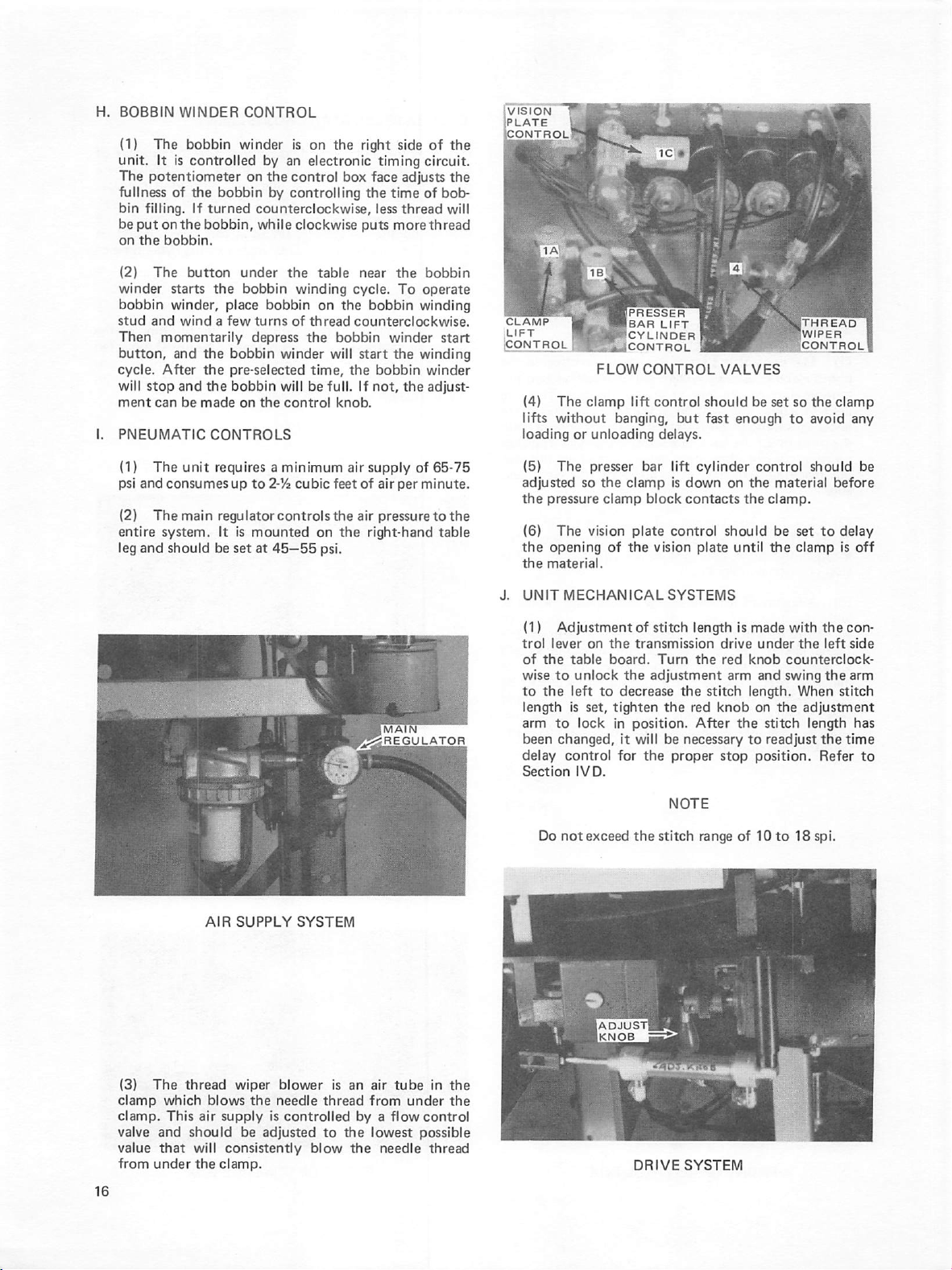
STOP
(1)
Attach
power
position.
I.
Operate
single
layer
properly;
by
15°
After
calibrated,
POSITION
The
the
the
control
photo-electric
tentiometers
used
to
or
the
position
ing
edge.
(2)
TION.
through
stop
adjust
the
beginning
position
control
machine
The
fine
The
the
position
coarse
the
air
to
switch.
the
of
thin
and
increments,
machine
electric
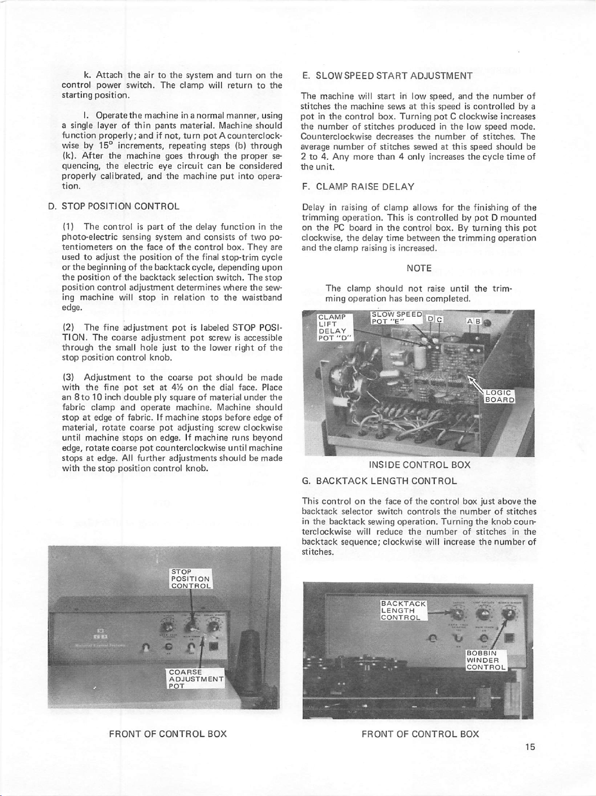
CONTROL
is
sensing
on
the
the
of
of
the
the
The
machine
pants
if
not,
repeating
goes
eye
and
the
part
of
system
face
of
position
the
backtack
backtack
adjustment
will
stop
in
adjustment
adjustment
small
hole
just
control
knob.
system
clamp
in a normal
material.
turn
and
will
Machine
pot B counterclock
steps
through
circuit
machine
the
and
the
of
the
cycle,
selection
determines
relation
pot
is
pot
to
the
can
put
delay
function
consists
control
final
stop-trim
depending
switch.
where
to
the
labeled
screw
the
lower
turn
on
return
to
manner,
should
(b)
through
proper
be
considered
into
opera
in
of
two
box.
They
The
the
waistband
STOP
POSI
is
accessible
right
of
the
the
using
se
the
po
are
cycle
upon
stop
sew
the
E..
SLOW
SPEED
The
machine
stitches
pot
the
Counterclockwise
average
2
the
F.
Delay
trimming
on
in
the
number
to
4.
unit.
CLAMP
in
the
the
control
number
Any
raising
operation.
PC
clockwise,
and
the
clamp
The
ming
CLAMP
LIFT
DELAY
POT
"D"
START
will
start
machine
box.
of
stitches
decreases
of
more
than 4 only
RAISE
of
board
in
the
delay
raising
clamp
should
operation
SLOW
POT
ADJUSTMENT
in
low
sews
at
this
Turning
produced
the
stitches
DELAY
clamp
This
is
the
control
time
between
is
increased.
NOTE
sewed
allows
controlled
not
has
been
SPEED'
"C"
speed,
and
the
speed
is
controlled
pot C clockwise
in
the
low
number
at
this
increases
for
box.
the
raise
until
speed
of
stitches.
speed
the
cycle
the
finishing
by
pot D mounted
By
turning
trimming
the
completed.
number
of
by
increases
mode.
The
should
time
of
the
this
pot
be
of
operation
trim
a
(3)
Adjustment
with
the
fine
an
8to
10
inch
fabric
clamp
stop
at
material,
until
edge,
stops
with
edge
rotate
machine
rotate
at
edge.
the
stop
to
pot
set
double
and
operate
of
fabric.
coarse
stops
coarse
pot
Ail
further
position
the
coarse
at
ply
If
machine
pot
on
edge.
counterclockwise
control
pot
on
the
of
material
stops
machine
should
dial
Machine
before
screw
472
square
machine.
adjusting
If
until
adjustments
knob.
should
runs
be
made
face.
Place
under
the
should
edge
of
clockwise
beyond
machine
be
made
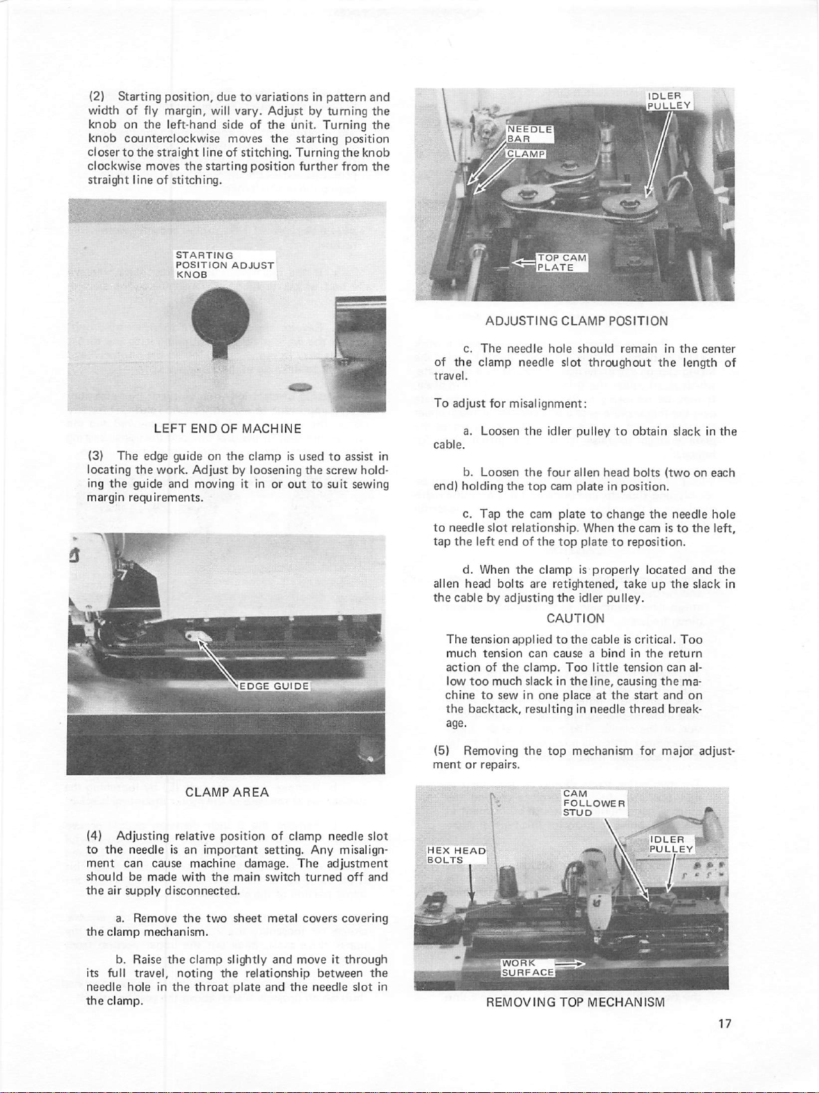
G.
BACKTACK
This
control
backtack
in
the
terclockwise
backtack
stitches.
on
selector
backtack
will
sequence;
INSIDE
LENGTH
the
face
switch
sewing
operation.
reduce
clockwise
CONTROL
CONTROL
of
the
control
controls
the
number
will
BOX
box
just
the
number
Turning
increase
the
of
stitches
the
BOBBIN
WINDER
CONTROL
]
LOGIC
1
board!
above
of
knob
number
I
the
stitches
coun
in
the
of
FRONT
OF
CONTROL
BOX
Revised
Sept.
1974
FRONT
OF
CONTROL
BOX
Page 21
k.
Attach
control
starting
a
function
wise
(k).
power
position.
I.
Operate
single
layer
by
After
properly;
15°
quencing,
properly
tion.
D.
STOP
(1)
calibrated,
POSITION
The
control
photo-electric
tentiometers
used
to
or
the
position
ing
adjust
the
beginning
position
control
machine
edge.
(2)
The
fine
TION.
The
through
stop
the
position
the
air
switch.
the
machine
of
thin
and
increments,
the
machine
the
electric
and
CONTROL
is
part
sensing
on
the
face
the
position
of
the
of
the
backtack
adjustment
will
stop
adjustment
coarse
adjustment
small
hole
control
knob.
to
the
system
The
clamp
in a normal
pants
material.
if
not,
turn
repeating
goes
through
eye
circuit
the
machine
of
the
system
backtack
and
of
the
of
the
cycle,
selection
determines
in
relation
pot
is
pot
just
to
and
turn
on
will
return
to
manner,
Machine
should
pot A counterclock
steps
(b)
through
the
proper
can
be
considered
put
into
opera
delay
function
consists
control
final
stop-trim
box.
of
They
in
two
depending
switch.
to
labeled
screw
the
lower
where
the
waistband
STOP
is
accessible
right
The
the
POSI
of
the
the
using
se
the
po
are
cycle
upon
stop
sew
the
E.
SLOW
SPEED
The
machine
stitches
pot
in
the
number
Counterclockwise
average
2
to
4.
the
unit.
F.
CLAMP
Delay
trimming
on
the
clockwise,
and
the
The
ming
CLAMP
LIFT
DELAY
POT
will
the
machine
the
control
of
number
Any
more
RAISE
in
raising
operation.
PC
board
the
delay
clamp
raising
clamp
operation
"D"
stitches
START
start
in
sews
box.
Turning
produced
decreases
of
stitches
than 4 only
DELAY
of
clamp
This
in
is
the
control
time
between
Is
increased.
NOTE
should
has
been
SLOW
SPEI
POT
"E"
ADJUSTMENT
low
speed,
at
this
speed
pot C clockwise
in
the
the
number
sewed
at
increases
allows
for
controlled
box.
the
not
raise
completed.
and
the
is
controlled
low
of
this
speed
the
the
finishing
by
pot D mounted
By
turning
trimming
until
the
number
increases
speed
mode.
stitches.
should
cycle
time
of
this
operation
trim
by
The
the
pot
of
a
be
of
(3)
Adjustment
with
the
an
8to
10
fabric
clamp
stop
at
material,
until
edge,
stops
witii
edge
rotate
machine
rotate
at
edge.
the
stop
fine
pot
inch
double
and
of
stops
coarse
All
position
to
the
coarse
set
at
472
ply
square
operate
fabric.
coarse
pot
^rther
machine.
If
machine
pot
adjusting
on
edge.
counterclockwise
adjustments
control
pot
on
the
of
stops
If
machine
knob.
should
material
dial
be
face.
under
Machine
before
screw
clockwise
runs
until
should
made
Place
the
should
edge
of
beyond
machine
be
made
G.
BACKTACK
This
control
backtack
in
terclockwise
backtack
stitches.
the
backtack
selector
sequence;
on
sewing
will
INSIDE
the
LENGTH
face
switch
operation.
reduce
clockwise
CONTROL
CONTROL
of
the
controls
the
number
will
BOX
control
the
box
number
Turning
of
increase
;
LOGIC
board!
just
above
of
the
knob
stitches
the
number
I
the
stitches
coun
in
the
of
FRONT
OF
CONTROL
BOX
FRONT
OF
CONTROL
BOX
Page 22
H.
BOBBIN
(1)
unit.
The
fullness
bin
be
put
on
the
(2)
winder
bobbin
stud
Then
button,
cycle.
will
ment
PNEUMATIC
(1)
psi
and
(2)
entire
leg
and
WINDER
The
bobbin
It
is
controlled
CONTROL
winder
potentiometer
of
the
filling.
on
bobbin.
The
starts
and
bobbin
If
turned
the
bobbin,
button
the
winder,
place
wind a few
under
bobbin
momentarily
and
the
bobbin
After
the
pre-selected
stop
and
the
bobbin
can
be
made
on
CONTROLS
The
unit
requires a minimum
consumes
The
main
system.
should
up
regulator
It
is
be
set
is
on
the
by
an
on
the
control
by
controlling
electronic
right
box
the
face
counterclockwise,
while
clockwise
the
winding
bobbin
turns
of
thread
depress
the
winder
time,
will
be
the
control
to
2-72
cubic
controlsthe
mounted
at
45—55
puts
table
near
cycle.
on
the
bobbin
counterclockwise.
bobbin
will
start
the
full.
If
not,
knob.
air
supply
feet
of
air
on
the
right-hand
psi.
side
timing
of
circuit.
adjusts
time
of
less
thread
more
thread
the
bobbin
To
operate
winding
winder
the
winding
bobbin
winder
the
adjust
of
65-75
air
per
minute.
pressure
to
table
the
the
bob
will
start
the
VISION
PLATE
CONTROL
(4)
lifts
loading
(5)
adjusted
the
pressure
(6)
the
opening
the
material.
1
FLOW
The
clamp
without
or
unloading
The
presser
so
the
clamp
The
vision
of
CONTROL
lift
control
banging,
delays.
bar
lift
clamp
is
block
plate
control
the
vision
VALVES
should
but
fast
cylinder
down
on
contacts
should
plate
be
set
enough
control
the
material
the
clamp.
be
until
the
so
the
to
avoid
should
set
clamp
clamp
before
to
delay
is
any
be
off
AIR
SUPPLY
SYSTEM
J.
(1)
trol
to
Section
UNIT
MECHANICAL
Adjustment
lever
of
the
table
wise
to
the
length
is
arm
to
been
changed,
delay
control
Do
not
on
the
board.
unlock
left
to
set,
lock
IV
D.
exceed
SYSTEMS
of
stitch
transmission
Turn
the
adjustment
decrease
tighten
in
the
position.
it
will
be
for
the
the
stitch
length
drive
the
red
the
stitch
red
knob
After
necessary
proper
stop
NOTE
range
is
made
under
knob
arm
and
length.
on
the
stitch
to
readjust
position.
of
10
with
the
the
left
counterclock
swing
the
When
the
adjustment
length
the
Refer
to
18
spi.
con
side
arm
stitch
has
time
to
(3)
The
clamp
clamp.
valve
and
value
that
from
under
thread
w^ich
This
wiper
blows
air
supply
should
be
will
consistently
the
clamp.
blower
the
needle
is
controlled
adjusted
is
thread
to
blow
an
air
tube
from
by a flow
the
lowest
the
needle
in
under
control
possible
thread
the
the
DRIVE
SYSTEM
Page 23
(2)
Starting
width
knob
on
knob
closer
to
clockwise
straight
position,
of
fly
margin,
the
counterclockwise
the
straight
moves
line
of
due
will
left-hand
side
line
the
starting
stitching.
to
variations
vary.
Adjust
of
the
moves
of
the
stitching.
position
in
pattern
by
turning
unit.
Turning
starting
position
Turningthe
further
from
and
the
the
knob
the
TOP
PLATE
CAM
{3}
The
locating
ing
margin
the
the
guide
requirements.
LEFT
edge
work.
END
guide
Adjust
and
moving
on
OF
MACHINE
the
clamp
by
loosening
it
in
EDGE
or
GUIOi
is
used
the
out
to
screw
to
suit
assist
in
hold
sewing
c.
of
the
travel.
To
adjust
a.
end)
holding
c.
to
needle
tap
the
d.
alien
the
cable
The
much
action
low
chine
the
age.
ADJUSTING
The
needle
clamp
needle
for
misalignment:
Loosen
b.
Loosen
the
Tap
the
slot
relationship.
left
end
When
the
head
bolts
by
adjusting
tension
too
applied
tension
of
the
much
to
sew
backtack,
CLAMP
hole
should
slot
the
idler
pulley
the
four
alien
top
cam
plate
cam
plate
of
the
top
clamp
are
retightened,
the
CAUTION
to
can
clamp.
slack
in
resulting
the
cause a bind
Too
in
the
one
place
in
POSITION
remain
throughout
to
obtain
head
bolts
in
position.
to
change
When
the
plate
to
reposition.
is
properly
take
idler
pulley.
cable
is
critical.
in
little
tension
line,
causing
at
the
start
needle
thread
in
the
slack
(two
the
needle
cam
is
located
up
the
the
return
can
the
and
break
the
center
length
in
on
to
the
and
slack
Too
al
ma
on
of
the
each
hole
left,
the
in
(5)
Removing
ment
or
repairs.
(4)
to
the
ment
should
the
air
the
clamp
its
full
needle
the
clamp.
Adjusting
needle
can
be
supply
a.
b.
relative
is
cause
made
disconnected.
Remove
mechanism.
Raise
the
travel,
hole
in
the
CLAMP
an
machine
witf^
the
clamp
noting
AREA
position
important
damage.
the
main
two
sheet
slightly
the
throat
plate
of
clamp
setting.
The
switch
metal
and
move
relationship
and
the
needle
Any
adjustment
turned
covers
it
between
needle
slot
misalign
off
and
covering
through
the
slot
in
HEX
BOLTS
HEAD
[WORK
REMOVING
the
SURFACEl
top
mechanism
CAM
FOLLOWER
STUD
.
TOP
MECHANISM
for
'IDLER
pulley!
major
I
» m f
r " !■
adjust
"
Page 24
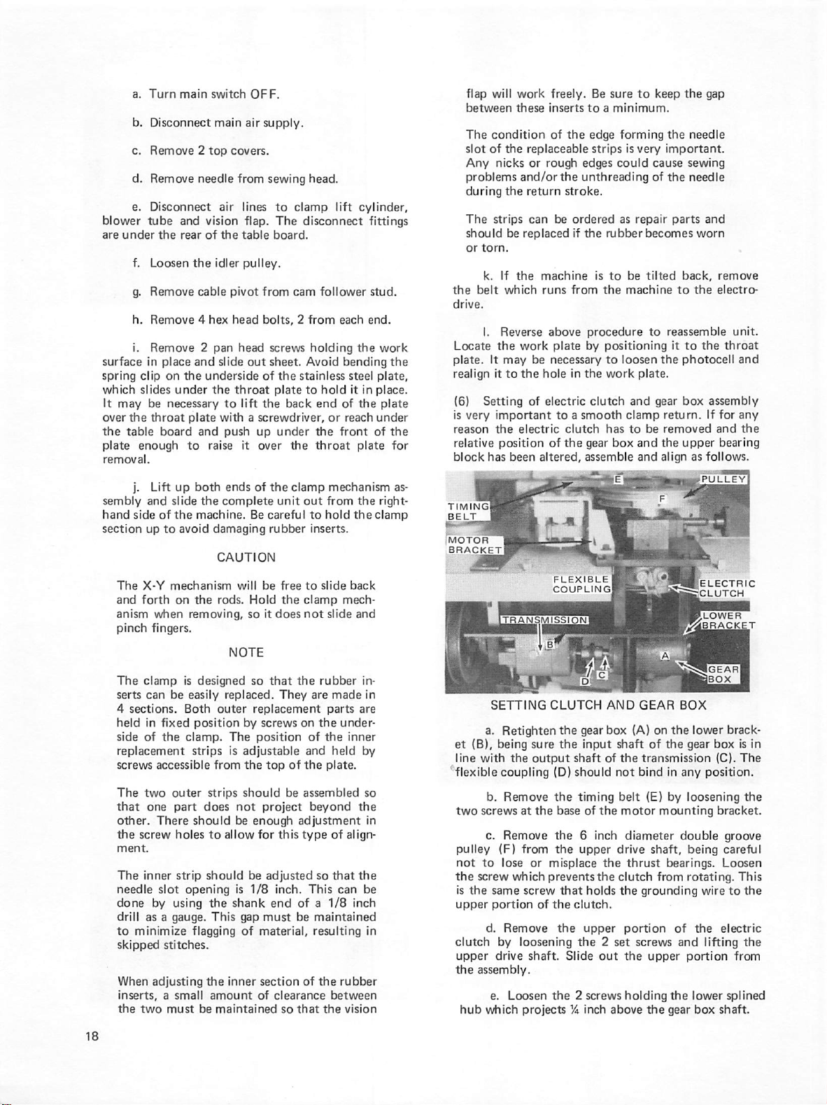
a.
b.
c.
d.
e.
blower
are
under
f.
g.
h.
i.
surface
spring
which
It
over
the
plate
removal.
in
clip
slides
may
the
table
enough
j.
sembly
hand
side
section
The
and
up
X-Y
forth
anism
pinch
Turn
main
switch
Disconnect
main
Remove 2 top
Remove
Disconnect
tube
Loosen
Remove
the
needle
and
rear
the
cable
air
vision
of
the
idler
Remove 4 hex
Remove 2 pan
place
and
on
under
be
necessary
throat
board
Lift
up
and
slide
of
the
to
mechanism
on tiie
when
slide
the
underside
the
plate
with a screwdriver,
and
to
raise
both
the
complete
machine.
avoid
damaging
CAUTION
rods.
removing,
fingers.
OFF.
air
covers.
from
lines
flap.
table
pulley.
pivot
head
head
out
throat
to
lift
push
it
ends
of
Be
will
Hold
so
supply.
sewing
from
head.
to
clamp
The
disconnect
board.
cam
follower
bolts, 2 from
screws
holding
sheet.
of
the
up
over
be
Avoid
the
stainless
plate
to
back
under
the
the
clamp
unit
out
careful
rubber
free
to
the
clamp
it
does
not
end
the
throat
to
inserts.
lift
cylinder,
fittings
stud.
each
end.
the
bending
steel
hold
it
in
of
the
or
reach
front
plate
mechanism
from
the
hold
the
slide
back
mech
slide
and
work
the
plate,
place.
plate
under
of
the
for
as
right-
clamp
flap
between
The
slot
Any
problems
during
The
should
or
torn.
the
belt
drive.
Locate
plate.
realign
(6)
is
very
reason
relative
block
timing!
BELT
(MOTOR
BRACKET
will
work
these
condition
of
the
replaceable
nicks
or
and/or
the
return
strips
can
be
replaced
k.
If
the
which
I.
Reverse
the
work
It
may
be
it
to
the
Setting
of
important
^e
electric
position
has
been
1
TRANSMISSION!
freely.
inserts
to a minimum.
of
the
edge
rough
edges
the
unthreading
stroke.
be
ordered
if
the
machine
runs
from
above
procedure
plate
by
necessary
hole
in
the
electric
clutch
to a smooth
clutch
of
the
gear
altered,
assemble
FLEXIBLE
coupling!
Be
sure
to
forming
strips
is
very
could
cause
of
as
repair
rubber
becomes
is
to
be
tilted
the
machine
to
positioning
to
loosen
work
plate.
and
clamp
has
to
be
box
and
and
I
keep
the
gap
the
needle
important.
sewing
the
needle
parts
and
worn
back,
to
the
reassemble
it
to
the
the
photocell
gear
box
assembly
return.
removed
the
align
If
upper
as
follows.
Kelectric
^rBwer
W^iBRACK^
remove
electro-
unit.
throat
and
for
any
and
the
bearing
The
clamp
is
serts
can
4
sections.
held
in
side
of
replacement
screws
The
two
that
one
other.
the
screw
ment.
The
inner
needle
done
by
drill
as a gauge.
to
minimize
skipped
When
adjusting
inserts, a small
the
two
designed
be
easily
Both
fixed
position
the
clamp.
strips
accessible
outer
part
There
should
holes
strip
slot
opening
using
flagging
stitches.
must
be
NOTE
replaced.
outer
by
The
is
adjustable
from
the
strips
should
does
not
be
to
allow
should
is
the
shank
This
gap
of
the
inner
amount
maintained
so
that
the
They
are
replacement
screws
on
the
position
of
and
top
of
the
be
assembled
project
enough
for
be
adjusted
1/8
must
material,
section
of
beyond
adjustment
this
type
so
inch.
This
end
of a 1/8
be
maintained
resulting
of tiie
clearance
so
that
rubber
made
parts
under
the
inner
held
plate.
the
of
align
that
the
can
inch
rubber
between
the
vision
in
in
are
by
so
in
be
in
SETTING
a.
Retighten
et
(B),
line
flexible
two
the
is
upper
clutch
upper
the
being
with
b.
screws
c.
pulley
(F)
not
to
screw
the
same
portion
d.
by
drive
assembly.
e.
hub
which
coupling
Remove
Remove
lose
Remove
Loosen
CLUTCH
the
sure
the
the
output
(D)
the
at
the
base
the 6 inch
from
the
or
misplace
which
prevents
screw
that
of
the
the
loosening
shaft.
the 2 screws
projects
AND
gear
box
input
shah
of
should
timing
of
the
upper
the
the
holds
clutch.
upper
the 2 set
Slide
out
Va
inch
GEAR
(A)
on
shaft
of
the
not
belt
motor
the
transmission
bind
(E)
mounting
diameter
drive
shaft,
thrust
bearings.
clutch
from
the
grounding
portion
screws
the
upper
holding
above
the
BOX
the
lower
gear
in
any
position.
by
loosening
double
being
rotating.
wire
of
the
and
lifting
portion
the
lower
gear
box
brack
box
is
in
(C).
The
the
bracket.
groove
careful
Loosen
This
to
the
electric
the
from
splined
shaft.
Page 25
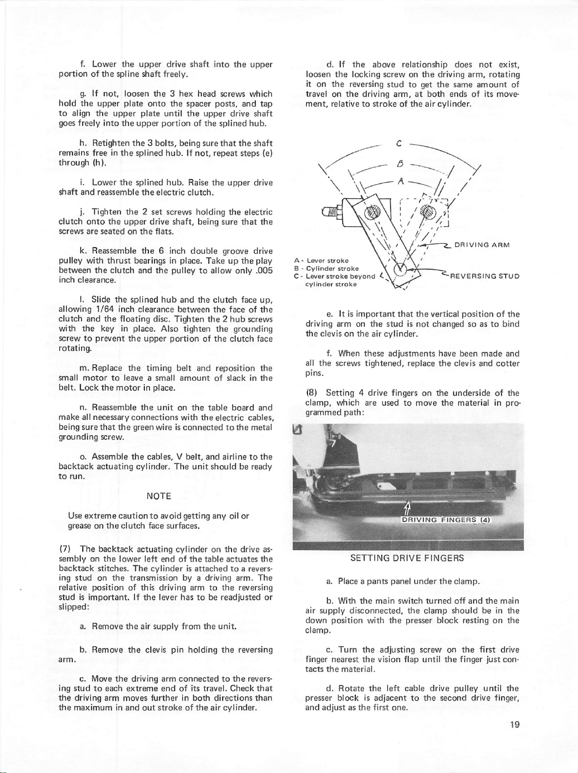
f.
portion
hold
to
goes
remains
through
shaft
clutch
screws
pulley
between
inch
allowing
clutch
with
screw
Lower
of
g.
If
the
upper
align
the
freely
h.
Retighten
free
(h).
i.
Lower
and
reassemble
j.
Tighten
onto
are
seated
k.
Reassemble
with
the
clearance.
I.
Slide
1/64
and
the
to
prevent
rotating.
m.
small
belt.
make
being
Replace
motor
Lock
n.
Reassemble
ail
necessary
sure
that
grounding
the
the
spline
not,
loosen
plate
upper
into
the
in
the
the
the 2 set
the
upper
thrust
clutch
the
inch
the
floating
key
in
to
leave a small
the
motor
the
screw.
upper
drive
shaft
freely.
the 3 hex
onto
the
plate
until
upper
portion
the 3 bolts,
splined
splined
the
hub.
hub.
electric
screws
drive
on
the
shaft,
flats.
the 6 inch
bearings
and
splined
the
hub
in
pulley
clearance
disc.
place.
the
upper
the
in
the
Tighten
Also
portion
timing
place.
unit
connections
green
wire
is
shaft
head
spacer
the
upper
of
the
being
sure
If
not,
Raise
the
clutch.
holding
being
double
place.
Take
to
allow
and
the
between
the 2 hub
tighten
of
belt
and
amount
on
the
table
with
the
connected
into
the
upper
screws
posts,
splined
that
repeat
clutch
the
and
drive
hub.
the
steps
upper
the
electric
sure
that
groove
up
the
only
face
face
of
which
shaft
shaft
drive
drive
play
.005
screws
the
grounding
the
clutch
face
reposition
of
slack
in
board
and
electric
to
cables,
the
metal
tap
(e)
the
up,
the
the
the
d.
loosen
it
on
travel
ment,
A - Lever
B - Cylinder
C • Lever
stroke
stroke
cylinder
e.
driving
the
clevis
f.
all
the
pins.
(8)
Setting 4 drive
clamp,
grammed
If
the
the
locking
the
reversing
on
the
relative
to
stroke
beyond
stroke
It
is
important
arm
on
on
the
When
screws
which
driving
these
tightened,
are
path:
above
relationship
screw
stud
arm,
stroke
of
\
\
that
the
stud
air
cylinder.
adjustments
fingers
used
to
on
the
driving
to
get
the
at
both
the
air
cylinder.
the
vertical
is
not
changed
replace
on
the
the
move
does
arm,
same
ends
dri\
DRIV
•REVERSING
position
so
have
been
clevis
underside
the
material
not
rotating
amount
of
its
move
ING
ARM
of
as
to
made
and
cotter
of
in
exist,
of
STUD
the
bind
and
the
pro
o.
Assemble
backtack
to
run.
Use
extreme
grease
(7)
The
sembly
on
backtack
ing
stud
relative
stud
position
is
important.
slipped;
a.
Remove tfie
b.
Remove
c.
ing
the
the
Move
stud
to
driving
maximum
actuating
the
caution
on
the
clutch
backtack
the
lower
stitches.
on
The
the
transmission
of
If
the
the
driving
each
extreme
arm
moves
in
and
cables, V belt,
cylinder.
actuating
left
NOTE
to
avoid
face
end
The
getting
surfaces.
cylinder
of
cylinder
by a driving
this
driving
the
lever
has
air
supply
from
clevis
pin
arm
connected
end
of
further
out
in
stroke
of
and
unit
should
any
on
the
table
is
attached
arm
to
to
be
the
holding
its
travel.
both
directions
the
air
airline
to
the
be
ready
oil
or
the
drive
as
actuates
the
to a revers
arm.
The
the
reversing
readjusted
or
unit.
the
reversing
to
the
revers
Check
that
than
cylinder.
a.
b.
air
supply
down
position
clamp.
c.
finger
nearest
tacts
the
d.
presser
and
adjust
SETTING
Place a pants
With
the
main
disconnected,
with tite
Tum
the
adjusting
the
vision
material.
Rotate
block
as
the
the
left
is
adjacent
first
DRIVING
DRIVE
panel
switch
the
presser
flap
cable
to
one.
FINGERS
under
turned
clamp
screw
until
drive
the
FINGERS
the
clamp.
off
should
block
on
the
the
finger
pulley
second
(4)
and
the
be
resting
on
first
just
until
drive
finger,
main
in
the
the
drive
con
the
Page 26
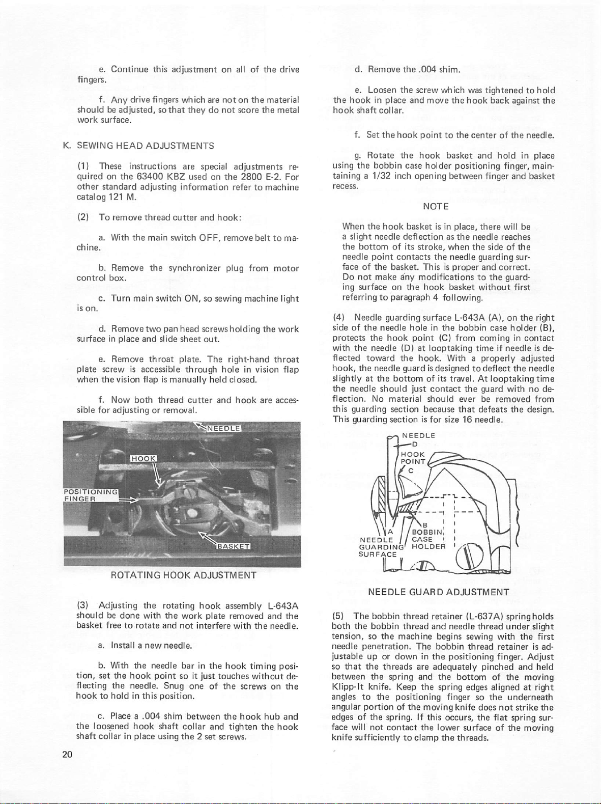
fingers.
should
work
K.
SEWING
(1)
quired
other
catalog
(2)
control
surface
plate
v\^en
sible
e.
Continue
f.
Any
be
adjusted,
surface.
HEAD
These
instructions
on
the
standard
121
M.
To
remove
a.
With
b.
Remove
box.
c.
Turn
d.
Remove
in
place
e.
Remove
screw
is
the
vision
f.
Now
for
adjusting
this
drive
fingers
so
that
ADJUSTMENTS
63400
the
main
both
KBZ
adjusting
thread
main
the
switch
two
pan
and
slide
throat
accessible
flap
is
thread
or
removal.
adjustment
which
they
are
used
information
cutter
switch
synchronizer
ON,
head
sheet
plate.
through
manually
cutter
on
are
not
do
not
special
on
the
and
hook:
OFF,
remove
plug
so
sewing
screws
out.
The
right-hand
hole
held
and
all
of
the
drive
on
the
material
score
the
metal
adjustments
2800
E-2.
For
refer
to
machine
belt
to
ma-
from
motor
machine
holding
in
closed.
hook
light
the
work
throat
vision
flap
are
acces
re
d.
Remove
e.
Loosen
the
hook
in
place
hook
shaft
collar.
f.
Set
the
g.
Rotate
using
the
bobbin
taining a 1/32
recess.
When
the
a
slight
the
needle
face
Do
ing
referring
(4)
side
of
protects
with
flected
hook,
slightly
the
needle
flection.
this
guarding
This
hook
needle
bottom
point
of
the
not
surface
Needle
the
the
guarding
basket.
make
on
to
paragraph 4 following,
guarding
the
needle
the
hook
needle
toward
needle
at
the
should
No
material
section
section
the
.004
shim.
the
screw
which
and
move
the
hook
point
to
the
hook
basket
case
holder
inch
opening
basket
deflection
of
its
stroke,
contacts
any
the
between
NOTE
is
in
as
when
the
needle
This
is
modifications
hook
basket
surface
hole
in
the
point
(D)
the
guard
bottom
NEEDLE
(C)
at
looptaking
hook.
is
designed
of
its
just
contact
should
because
is
for
With a properly
travel.
size
T-d
Ihook
/
pointZ^SS^:—\
/c
was
tightened
hook
back
the
center
of
and
hold
positioning
finger,
finger
place,
there
the
needle
the
will
reaches
side
of
guarding
proper
and
correct.
to
the
guard
without
L-643A
from
bobbin
coming
time
to
deflect
At
the
guard
ever
be
that
defeats
16
needle.
(A),
on
case
if
needle
looptaking
with
removed
to
hold
against
the
the
needle.
in
place
main
and
basket
be
the
sur
first
the right
holder
(B),
in
contact
is
de
adjusted
the
needle
time
no
de
from
the
design.
POSITIONING
FINGER
(3)
should
basket
tion,
flecting
hook
the
shaft
ROTATING
Adjusting
be
done
free
to
rotate
a.
Install a new
b.
With
the
set
the
hook
the
needle.
to
hold
in
c.
Place a .004
loosened
collar
hook
in
place
HOOK
the
rotating
with
and
needle.
needle
point
Snug
this
position.
shim
shaft
using
the
work
not
bar
so
collar
the 2 set
ADJUSTMENT
hook
plate
interfere
in
the
it
just
one
of
between
and
assembly
removed
with
the
hook
timing
touches
the
the
without
screws
hook
tighten
screws.
L-643A
and
needle.
posi
on
hub
the
hook
the
de
the
and
NEEDLE / /
GUARDING'
SURFACE
NEEDLE
(5)
The
both
the
tension,
needle
justable
so
so
penetration.
up
that
the
between
Klipp-lt
angles
angular
edges
face
knife
knife.
to
portion
of
the
will
not
sufficiently
\\a / /bobbinI
CASE
HOLDER
<
LX^
bobbin
bobbin
the
machine
or
down
threads
the
spring
Keep
the
positioning
of
spring.
contact
GUARD
thread
thread
The
the
to
clamp
ADJUSTMENT
retainer
and
needle
begins
bobbin
in
the
are
and
If
positioning
adequately
the
the
spring
finger
moving
this
occurs,
the
lower
the
knife
threads.
(L-637A)
thread
sewing
thread
pinched
bottom
edges
so
the
does
the
surface
springholds
under
with
the
retainer
finger.
and
of
the
aligned
flat
moving
at
underneatii
not
strike
spring
of
the
moving
slight
first
is
ad
Adjust
held
right
the
sur
Page 27
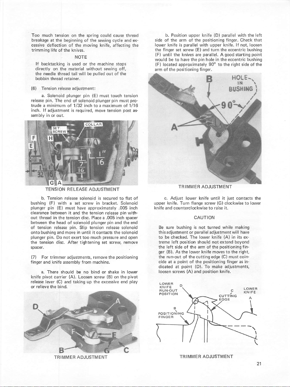
Too
much
tension
breakage
cessive
trimming
If
directly
the
bobbin
(6)
release
trude a minimum
inch.
sembly
at
the
deflection
life
of
backtacking
on
needle
thread
thread
Tension
a.
If
release
Solenoid
pin.
The
adjustment
in
or
out.
on
beginning
of
the
the
knives.
NOTE
is
used
the
material
tail
retainer.
adjustment:
plunger
end
of
of
1/32
is
required,
the
spring
of
the
moving
or
the
without
will
be
pulled
pin
(E)
solenoid
plunger
inch
to a maximum
move
could
cause
sewing
cycle
knife,
affecting
machine
sewing
out
must
touch
pin
tension
stops
off,
of
the
must
thread
and
ex
the
tension
pro
of
1/16
post
as
side
of
lower
the
finger
(F)
until
would
(F)
located
arm
of
b.
Position
the
arm
knife
is
parallel
set
screw
the
knives
be
to
have
approximately
the
positioning
upper
knife
of
the
positioning
with
(E)
and
are
parallel. A good
the
pin
finger.
(D)
upper
turn
hole
90°
o
parallel
finger.
knife.
the
eccentric
in
the
eccentric
to
the
right
HOLE..
BUSHING
with
the
Check
that
If
not,
loosen
bushing
starting
point
bushing
side
of
left
the
\
TENSION
b.
bushing
plunger
clearance
out
between
of
onto
plunger
the
spacer.
(7)
finger
knife
release
or
Tension
(F)
pin
between
thread
the
tension
bushing
pin.
tension
For
trimmer
and
a.
There
pivot
lever
relieve
the
^ET
i
SCREW!
I
RELEASE
release
with a set
(E)
must
in
the
tension
head
of
release
and
move
Do
not
disc.
adjustments,
knife
assembly
should
carrier
(C)
and
bind.
solenoid
have
it
and
solenoid
pin.
Slip
in
exert
After
tightening
be
(A).
Loosen
taking
ADJUSTMENT
is
xrew
secured
in
bracket.
approximately
the
tension
disc.
release
Place a .005
plunger
tension
until
it
contacts
too
much
pressure
set
remove
from
machine.
no
bind
or
screw
(B)
up
the
excessive
to
Solenoid
.005
pin
inch
pin
and
release
solenoid
the
solenoid
and
screw,
the
positioning
shake
in
on
the
end
flat
of
inch
with
spacer
the
end
open
remove
lower
pivot
play
c.
upper
knife
and
Be
this
to
be
treme
the
ger
the
cide
dicated
loosen
LOWER
KNIFE
RUN-OUT
POSITION
TRIMMER
Adjust
knife.
sure
adjustment
left
(B).
run-out
at a point
lower
Turn
counterclockwise
bushing
or
checked.
left
position
side
of
As
the
lower
of
the
of
at
point
screws
(A)
ADJUSTMENT
knife
flange
CAUTION
is
not
parallel
The
lower
should
the
arm
knife
cutting
the
positioning
(D).
and
position
until
screw
(G)
to
raise
turned
adjustment
knife
not
extend
of
the
positioning
moves
edge
(C)
To
make
knife.
CUTTING
EDGE
it
just
contacts
clockwise
it.
while
(A)
making
will
in
its
to
have
ex
beyond
fin
to
the
right,
must
coin
finger
as
in
adjustments,
LOWER
KNIFE
the
lower
B
POSITIONING
FINGER
TRIMMER
ADJUSTMENT
\
TRIMMER
ADJUSTMENT
Page 28
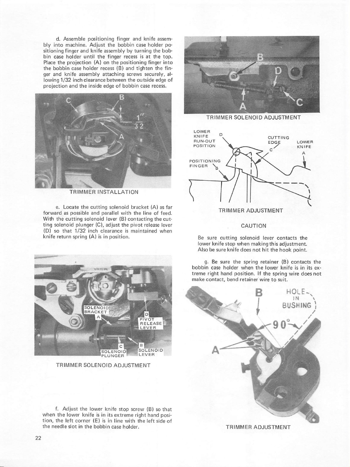
d.
bly
sitioning
bin
Place
the
ger
lowing
projection
Assemble
into
machine.
finger
case
holder
the
projection
bobbin
and
knife
1/32
case
and
positioning
and
until
holder
assembly
inch
clearance
the
inside
Adjust
knife
assembly
the
(A)
on
recess
attaching
edge
finger
the
bobbin
by
finger
recess
the
positioning
(B)
and
screws
between
of
bobbin
and
case
turning
is
tighten
the
outside
case
knife
assem
holder
po
the
bob
at
the
top.
finger
into
the
securely,
fin
edge
al
of
recess.
e.
forward
With
the
ting
solenoid
ID)
so
that
knife
return
TRIMMER
Locate
the
as
possible
cutting
plunger
1/32
spring
INSTALLATION
cutting
and
(C).
inch
(A)
parallel
lever
adjust
clearance
is
in
solenoid
solenoid
bracket
with
(B)
contacting
the
pivot
is
maintained
position.
the
(A)
as
line
of
feed.
the
release
lever
when
far
cut
LOWER
KNIFE
RUN-OUT
POSITION
POSITIONING
FINGER
Be
lower
Also
g.
bobbin
treme
make
contact,
TRIMMER
V
TRIMMER
sure
cutting
knife
be
sure
Be
sure
case
right
hand
SOLENOID
stop
when
knife
the
holder
position.
bend
ADJUSTMENT
CAUTION
solenoid
making
does
not
hit
spring
retainer
when
the
If
retainer
wire
ADJUSTMENT
CUTTING
EDGE
lever
contacts
this
adjustment.
the
hook
|B)
lower
knife
the
spring
to
suit.
LOWER
KNIFE
the
point.
contacts
is
in
its
wire
does
the
ex
not
1^
ISOLENOIQl-^
[bracket
PIVOT
release'
1
LEVER
SOLENOlDl
'PLUNGER
when
tion,
the
needle
TRIMMER
f.
Adjust
the
the
left
the
lower
corner
slot
in
SOLENOID
lower
knife
is
IE)
the
bobbin
knife
in
its
is
in
ADJUSTMENT
extreme
line
case
'
stop
with
holder.
fSOLENOID
Ilever
screw
(B)
right
the
left
so
hand
side
that
posi
of
TRIMMER
R
ADJUSTMENT
HOLE..
BUSHING
]
Page 29
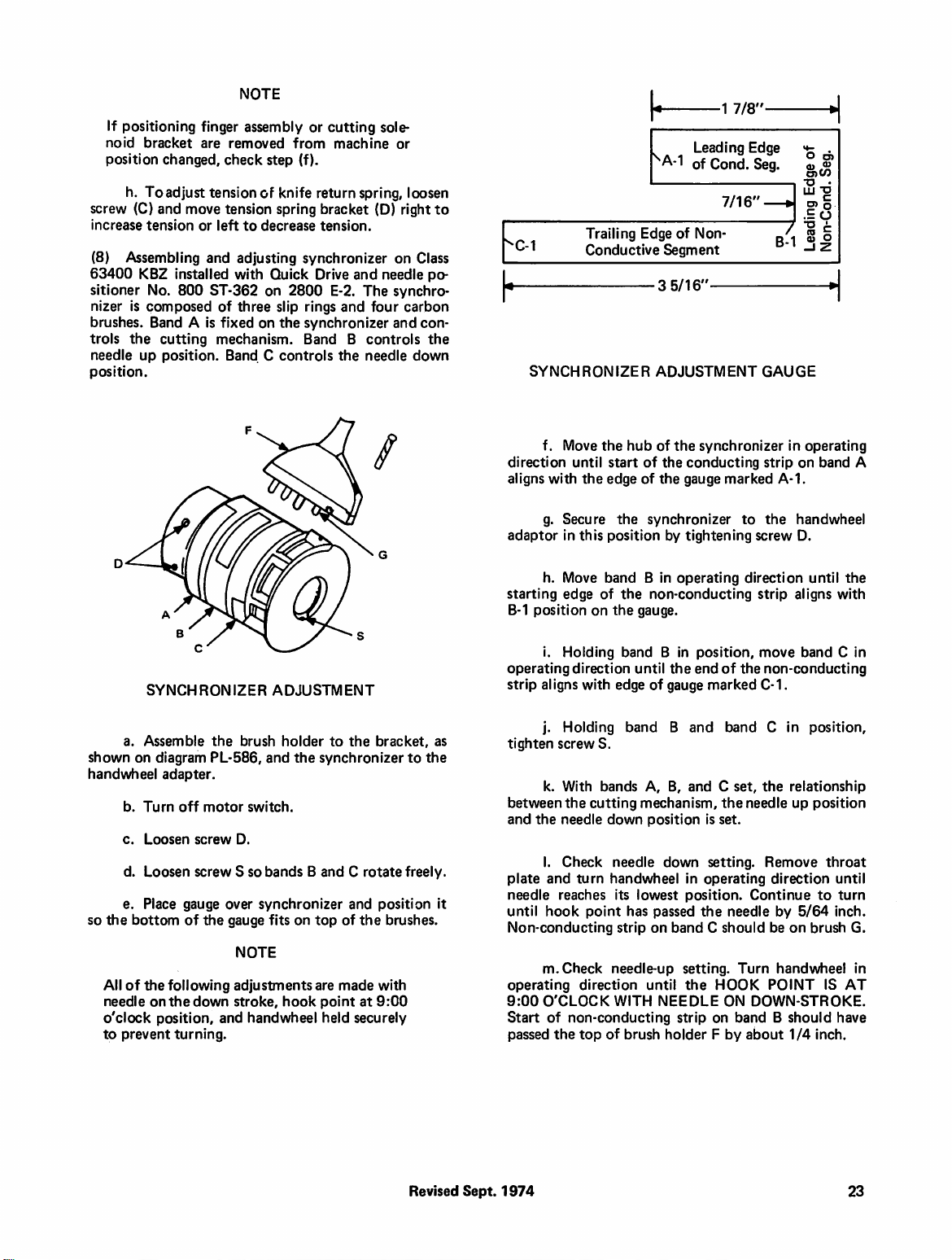
If
positioning
noid
bracket
position
h.
Toadjust
screw
(C)
increase
(8)
63400
sitioner
nizer
brushes.
trols
needle
tension
Assembling
KBZ
No.
is
composed
Band A is
the
up
position.
finger
are
removed
changed,
check
tension
and
move
tension
or
left
and
installed
800
ST-362
of
fixed
cutting
position.
mechanism.
Band C controls
NOTE
assembly
step
of
knife
or
from
(f).
spring
to
decrease
adjusting
with
three
synchronizer
Quick
on
2800
slip
rings
on
the
synchronizer
Band B controls
cutting
machine
return
spring,
bracket
tension.
Drive
and
E-2.
The
and
four
the
needle
sole
or
loosen
(D)
right
on
needle
synchro
carbon
and
to
Class
po
con
the
down
0-1
h
SYNCHRONIZER
f.
Move
direction
aligns
with
g.
adaptor
Secure
in
Trailing
Conductive
the
until
start
the
edge
the
this
position
^A-1
Edge
of
Segment
3
5/16'
ADJUSTMENT
hub
of
the
of
the
of
the
synchronizer
by
■1
7/8'
Leading
of
Cond.
7/16'
Non-
synchronizer
conducting
gauge
marked
to
tightening
Edge
Seg.
GAUGE
strip
the
screw
~7
B-1
in
on
A-1.
handwheel
D.
O
o)
C3)W
iS
"o
.EO
cq
X
0)
O
operating
band
A
SYNCHRONIZER
a.
Assemble
shown
on
handwheel
b.
Turn
c.
Loosen
d.
Loosen
e.
the
bottom
All
of
needle
Place
the
so
o'clock
to
prevent
diagram
adapter.
off
gauge
of
following
on
the
position,
turning.
the
brush
PL-586,
motor
switch.
screw
D.
screw S so
over
the
gauge
NOTE
adjustments
down
stroke,
and
handwheel
ADJUSTMENT
holder
to
the
and
the
synchronizer
bands B and C rotate
synchronizer
fits
on
hook
top
are
point
held
and
of
the
made
at
securely
bracket,
to
freely.
position
brushes.
with
9:00
the
as
h.
Move
starting
B-1
operating
strip
tighten
between
and
plate
it
needle
until
Non-conducting
operating
9:00
Start
passed
edge
position
i.
Holding
direction
aligns
with
j.
Holding
screw
k.
With
the
the
needle
I.
Check
and
turn
reaches
hook
point
m.
Check
direction
O'CLOCK
of
non-conducting
the
top
of
the
on
the
band B in
edge
band B and
S.
bands
cutting
down
needle
handwheel
its
has
strip
needle-up
WITH
of
brush
band B in
operating
non-conducting
gauge.
position,
until
the
end
of
gauge
marked
A,
B,
and C set,
mechanism,
position
lowest
passed
on band C should
down
in
position.
is
set.
setting.
operating
the
setting.
until
the
HOOK
NEEDLE
strip
on
holder F by
direction
strip
move
of
the
non-conducting
C-1.
band C in
the
relationship
the
needle
up
Remove
direction
Continue
needle
by
be
on
Turn
handwheel
POINT
ON
DOWN-STROKE.
band B should
about
1/4
until
aligns
with
band C in
position,
position
throat
until
to
turn
5/64
inch.
brush
IS
have
inch.
the
G.
in
AT
Revised
Sept.
1974
23
Page 30
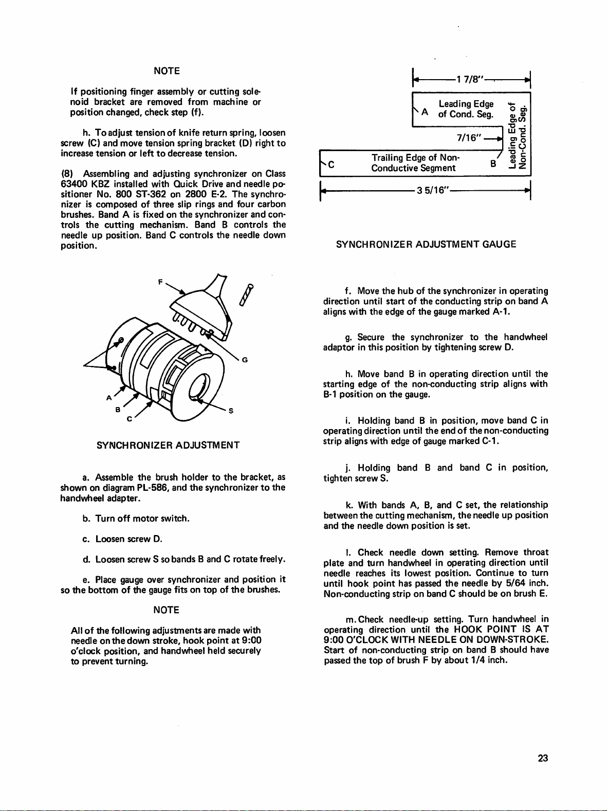
If
positioning
noid
bracket
position
h.
To
screw
(C)
increase
(8)
63400
sitioner
nizer
brushes.
trols
needle
position.
tension
Assembling
KBZ
No.
is
composed
the
up
finger
are
changed,
adjust
tension
and
move
or
left
and
installed
800
ST-362
Band A is
cutting
position.
NOTE
assembly
removed
check
of
tension
to
adjusting
with
of
three
fixed
on
mechanism.
or
from
step
(f).
knife
return
spring
decrease
bracket
tension.
synchronizer
Quick
Drive
on
2800
slip
rings
the
synchronizer
Band B controls
Band C controls
cutting
sole
machine
spring,
(D)
and
needle
E-2.
The
and
four
the
needle
or
loosen
right
to
on
Class
po
synchro
carbon
and
con
the
down
h
SYNCHRONIZER
f.
Move
direction
aligns
with
g.
adaptor
Secure
in
Trailing
Edge
Conductive
the
hub
until
start
the
edge
of
the
this
position
•1
7/8"-
Leading
^
A
of
Cond.
7/16'
of
Non-
Segment
3
5/16'
ADJUSTMENT
of
the
synchronizer
of
the
conducting
the
gauge
marked
synchronizer
by
tightening
Edge
Seg.
GAUGE
strip
to
screw
in
A-1.
the
handwheel
0)C/3
tS
"d
™
c:
o)
o
S
O
"O
c
CO
X
0)
o
H
operating
on
band
D.
A
SYNCHRONIZER
a.
shown
handwheel
so
/Assemble
on
diagram
b.
Turn
c.
Loosen
d.
Loosen
e.
Place
the
bottom
All
of
the
needle
on
o'clock
to
petition,
prevent
the
PL-586,
adapter.
off
motor
screw
screw S so
gauge
over
of
the
gauge
following
the
down
and
turning.
ADJUSTMENT
brush
holder
to
and
the
switch.
D.
bands B and C rotate
the
synchronizer
synchronizer
fits
on
top
of
NOTE
adjustments
stroke,
handwheel
hook
are
made
point
held
bracket,
and
position
the
brushes.
with
at
9:00
securely
as
to
the
freely.
it
h.
Move
starting
B-1
position
i.
operating
strip
aligns
j.
tighten
k.
between
and
the
I.
plate
and
needle
until
hook
Non-conducting
m.
operating
9:00
O'CLOCK
Start
of
passed
the
band B in
edge
of
the
on
the
Holding
band B in
direction
with
edge
Holding
screw
With
the
needle
Check
turn
reaches
band B and
S.
bands
cutting
down
needle
handwheel
its
point
strip
Check
needle-up
direction
WITH
non-conducting
top
of
brush F by
operating
non-conducting
gauge.
position,
until
the
end
of
gauge
of
marked
band C in
A,
B,
and C set,
mechanism,
position
down
lowest
has
passed
on
the
is
set.
setting.
in
operating
position.
the
band C should
setting.
until
the
HOOK
NEEDLE
strip
on
ON
about
direction
strip
the
until
aligns
move
band C in
non-conducting
C-1.
position,
the
relationship
needle
up
position
Remove
direction
Continue
needle
Turn
to
by
5/64
be
on
brush
handwheel
POINT
DOWN-STROKE.
band B should
1/4
inch.
the
with
throat
until
turn
inch.
E.
in
IS
AT
have
23
Page 31

A.
CLEANING
(1)
mulated
age,
air
nozzle
zle
to
in
needle
plate
of
the
(2)
remove
(3)
odically
blowing
larger
color.
(4)
cleaned
cleaning
abrasive
B.
LUBRICATION
Twice
daily
remove
lint
will
cause
and/or
failure
is
provided
a.
Remove
blow
guarding
b.
Blow
to
remove
throat
c.
Blow
bobbin
inside
the
across
lint
plate.
off
the
Remove 2 top
lint.
Wipe
rods
Remove
filter
The
and
by
dry
clean
washing
with
air.
unit
should
synchronizer
with a dry
fluid.
Do
material.
lint
skipped
of
the
Klipp-lt
on
the
case
hook
area.
top
of
that
has
Klipp-lt
covers
with a clean
the
with
The
white
be
bands
cloth
and
not
use
from
hook
stitches,
unit
to
and
and
upward
hook
and
collected
knife
at
least
brown
spirits,
filter
replaced
should
if
emery
thread
to
cut
properly.
clean
the
bobbin.
to
bottom
on
area.
once a month
oily
rag.
filter
element
kerosene,
element
when
be
necessary a non-oily
paper
or
SECTION
GENERAL
area.
MAINTENANCE
Accu
break
An
lint.
Use
air
noz
remove
the
of
throat
bottom
lint
and
peri
etc.,
and
from
the
it
changes
periodically
any
other
V
d.
Periodically
and
seat
cleaning
bottom
(3)
Texaco
the
30
initial
6
Some
ings.
EP
NEVER
OIL.
ing
oil
never
(4)
with
drives
level
is
in
SAE
fluid
e.
Drain
of
The
Pinnacle
factory.
days
(8
oil
months
reducers
They
Grease,
It
will
in
rapid
should
any
The
the
are
should
at
least
housing
40
detergent
clean
and
the
small
and
blowing
off
the
gear
change,
(8
should
or
OVERFILL
be
higher.
transmission
proper
permanently
1/2
any
bowl.
reducer
Cylinder
This
oil
hours
daily)
the
10
oil
hours
to
have
be
equal,
after
cause
oil
wear
of
filled
to
amount
be
checked
full.
with
When
transmission
should
grease
oil
motor
adjusting
felt
filter
off
with
contaminants
contains
should
Oil
of
be
unit
the
(a
Texaco
replaced
operation.
be
changed
duty).
fittings
lubricated
THE
leakage
seals,
the
drive
lubricated.
periodically
each
GEAR
oil
runs
and
with
200
and
bearings
level
kind
necessary,
No.
oil.
screw
needle
valve
by
swishing
air.
or
water
in
proper
amount
product)
after
at
the
Texaco
hours
of
REDUCER
overheating,
and
plug
or
in
oil
at
the
However,
to
be
sure
fill
through
400
from
the
After
about
every
upper
bear
Multifax
operation.
WITH
result
gears.
gauge
and
is
filled
factory.
the
the
lubricant
in
a
the
of
first
this
The
and
All
oil
case
hole
or
(1)
Check
ing
oil
sight
oil
as
required.
and
lubrication.
(2)
Check
of
one
drop
sufficient
system.
the
turn
bowl.
line.
sure
sight
stream
gives
From
turns
further
adjusting
for
a.
To
air
pressure
of
the
b.
Fill
c.
Replace
rebuilds
gauge.
by
turning
less
oil
OFF
of
serves
screw
the
sewing
gauge
See
the
unit
of
oil
proper
fill
the
and
fill
plug
to
top
fill
inside
Control
and
out
to
FULL
the
adjusting
no
while
head
and
catalog
lubricator
every
lubricator,
with
plug
the
the
gives
purpose.
oil
adding
Union
No.
once a week. A setting
50
cycles
lubrication
you
remove
vents
the
NOTE
the
the
SAE
10
tightly.
bowl,
oil
rate
of
adjustment
more.
OPEN
screw.
NEVER
the
air
pressure
level
daily
Special
121 M for
of
unit
operation
of
the
need
not
fill
plug.
air
pressure
or
lighter
As
soon
will
drip
oil
requires
Turning
through
entering
screw.
only
it
take
is
on.
by
examin
spec.
86
proper
care
pneumatic
turn
off
The
first
from
the
oil
to
fill
as
air
pres
the
the
Turning
air
2
out
out
is
in
(5)
Idler
plate
should
on
the
(6)
Drive
drive
pulley
months.
(7)
The
every 2 years.
C.
REPLACEMENT
(1)
Replace 2 carbon
Auxiliary
(2)
Replace
every
12
(3)
Check
months
(4) A check
a
service
that
plant
is
inspected
will
prevent
pulley
bearing
bearings
be
greased
housing.
pulley
bearings
require a thin
electro-drive
Drive
every
round
list
follows
belt
as
months.
synchronizer
and
replace
or
inspection
mechanics
periodically. A good
unnecessary
on
top
every 6 months.
underneath
coat
of
cup
should
brushes
12
required.
use
be
(998-237)
months.
(998-235)
carbon
this
section,
call
is
made.
this
check
maintenance
downtime.
cleaned
right
side
Zerk
the
grease
and
on
on
Quick
brushes
to
be
used
We
recommend
list
when
of
cam
fitting
is
left-hand
every
6
greased
the
Quick
Drive
every
12
when
the
unit
program
25
Page 32

UNIT
PART
CLEANING,
LUBRICATION.
WEEKLY
AND
REPLACEMENT
MONTHLY
PROGRAM
6
MONTHS
1
YEAR
CHECK
Clamp
Rotary
Throat
Air
Trimming
Bobbin
Wire
Synchronizer
Vee
CLEAN
Air
Cam
Cam
X-Y
CONDITION
AND/OR
Rubber
Hook
Plate
Tubes
to
Clamp
Knives
Thread
Cables
Belts
AND
Spring
LUBRICATE
Filter & Regulator
Plate
Roller
Rods
CLEAN
X
X
X
X
X
X
X
X
X
X
X
X
X
1
Transmission
Gear
Box
REPLACEMENT
Aux.
Motor
Synchronizer
Round
Belt
Brushes
Brushes
on
Quick
Drive
X
X
X
X
X
26
Page 33

SECTION
PARTS
VI
LISTS
REF
NO
1
8
g
10
11
12
PART
NO
RM-3417
61377J
RM-2748A
RM-3376
RM-3627
RM-3443
RM-3402
61477C
109
61392F-14
612926
RM-3312-1
660-398
RM-3343
998-264
DESCRIPTION
Bobbin
Assembly
Pulley
Switch
Switch
Switch
Knob
Stainless
Table
Tension
Tension
Tension
Tension
Filter
F.R.O.
Right
Bobbin
i
Motor
Shaft
SPST
Steel
Bracket
Disc
Spring
Nut
Combo
Cover
Switch
AMT
REQ
1
1
1
'
1
3
1
1
2
1
1
1
1
1
1
B
LI
REF
NO
1
^^9
8
PART
RM-3349
L-643A
L-639A
: RM-2385D
L-637A
L-636A
51292F-5
RM-3494
NO
DESCRIPTION
Cutting
Rotating
1
Assembly
Needle
Throat
Bobbin
Retainer
Bobbin
Holder
ing
Spring
Throat
Solenoid
Hook
Bar
Plate
Thread
Thread
Position
Finger
Plat^
Screw
AMT
REQ
1
1
1
1
1
1
1
2
Page 34

SECTION
PARTS
VI
LISTS
REF
NO NO
1
8
9
10
11
12
PART
RM-3417
61377J
RM-2748A
RI\/I-3376
RM-3627
RM-3443
RM-3402
61477C
109
61392F-14
612926
RM-3312-1
660-398
RM-3343
998-264
DESCRIPTION
Bobbin
Motor
Assembly
Pulley
Shaft
Switch
SPST
Switch
Switch
Knob
Stainless
Table
Tension
Tension
Tension
Tension
Tension
F.R.O.
Combo
Right
Cover
Bobbin
Switch
Steel
Bracket
Disc
Spring
Nut
Filter
AMT
REQ
m
1
1
1
1
3
1
1
2
1
1
1
1
1
1
B
IB
.CT-^
'fit
0
A,
j Fl
REF
NO
1
8
PART
RM-3349
L-643A
L-639A
RM-2385D
L-637A
L-636A
51292F-5
RM-3494
NO
DESCRIPTION
Cutting
Solenoid
Rotating
Assembly
Needle
Throat
Bobbin
Bobbin
Retainer
Holder
ing
Finger
Bar
Plate
Thread
Thread
Spring
Throat
Plate
Hook
Position
Screw
AMT
REQ
1
1
1
1
1
1
1
2
El
B
m
B
Page 35

REF
NO
PART
NO
DESCRIPTION
AMT
REQ
B
B
B
B
RM-3600
1
21262H-450
21261M-410
RM-2836
RM-2838D
RM-2520
RM-3080D
RM-2874D
RM-3674
RI\/l-3675
RM-3676
478-12
RI\/I-2606D
RM-2980B
RM-3046D
PART
NO
Vee
Belt
Idler
Vee
Belt
Vee
Belt
Pulley
6"
Dia.
Input
Shaft
DESCRIPTION
Garment
Cylinder
Lift
Wedge
Lift
Wedge
Screw
Lift
Wedge
Bearings
Clamp
Plate
1/8"
Tubing
71"
Long
No.
1032 X 5/16
H.H.
Sems
Sheave
1/2"
3/8"
Pulley
Stop
Clevis
Pivot
1
1
1
1
1
1
1 RM-3450
F'
2 RM-3460
3 RM-3211-3
4 RM-3525
5 RM-3611
PART
NO
DESCRIPTION
Switch
Plate
1-3/8 U Bolt
w/Nuts
3/8-16
H.N.
Start
Switch
Treadle
Start
Plate
Switch
/Xssembly
Shown)
8-32 X 3/8
(Not
S.H.S.
Page 36

REF
NO
1
2
3
4
5
6
PART
NO
RM-36Q0
21262H-450
21261M-410
RM-2836
RM-2838D
RM-2520
DESCRIPTION
Vee
Belt
Idler
Vee
Belt
Vee
Belt
Pulley
6"
Dia.
Input
Shaft
Sheave
1/2"
3/8"
Pulley
AMT
REG
1
1
1
1
1
1
%
PART
NO
DESCRIPTION
RM-SOSOD
RM-2874D
RM-3674
RM-3675
RM-3046D
PART
1 I
RM-3450
RM-3460
3 RM-3211-3
4 RM-3525
5 RM-3611
6 22652A-6
NO
Garment
Stop
Cylinder
Lift
Wedge
Lift
Wedge
Screw
Lift
Wedge
Bearings
Clamp
Plate
1/8"
Tubing
71"
Long
No.
10-32 X 5/16
H.H.
Sems
DESCRIPTION
Switch
Plate
1-3/8 U Bolt
w/Nuts
3/8-16
H.N.
Start
Switch
Treadle
Start
Assembly
Plate
Switch
(Not
Shown)
8-32 X 3/8
S.H.S.
Clevis
Pivot
Revised
Sept.
1974
Page 37

RM-3048-3
RM-3048-4
RM-2748A
RM-3376
8 RM-3627
RM-3088-8
10
RM-3088-7
11
RM-3088-3
15
RM-3620
Not
shown
PART
NO
(located
under
Transformer
Fuse
Holder
.3
Amp 3 AG
Fuse
.3
Amp 3 AG
Fuse
3.
Amp
Switch
(Clamp)
Switch
Main
Switch
(Backtack)
500 K Pot
(Backtack)
50 K Pot
Position
100K
Pot
Position
"Piggy
350K
Pot
Pilot
Lite
Control
Printed
Board
Power
Board
control
box)
Fuse
SPST
DPST
2PDT
Stop
Stop
Back"
Bobbin
Logic
Circuit
PC
RM-3406
671
A-1
RM-3316
RM-3410
PART
NO
DESCRIPTION
Cylinder
Bracket
Cylinder
Cylinder
Quick
Modified
Rod
Motor
End
Revised
Sept.
1974
Page 38

mi
B
■1
■1
B
B
REF
NO
10
11
12
13
14
15
1
8
9
PART
RM-3612
RM-2737A
RM-3048-3
RM-3048-3
RM-3048-4
RM-2748A
RM-3376
RM-3627
RM-3088-8
RM-3088-7
RM-3a88-3
RM-3088-4
RM-2749A
RM-3619
RM-3620
NO
DESCRIPTION
Transformer
Fuse
Holder
.3
Amp 3 AG
Fuse
.3
Amp 3 AG
Fuse
3.
Amp
Fuse
Switch
SPST
(Clamp)
Switch
Switch
DPST
Main
2PDT
(Backtack)
500 K Pot
(Backtack)
50 K Pot
Position
lOOK
Position
"Piggy
350K
Pilot
Control
Printed
Board
Power
Board
Stop
Pot
Back"
Pot
Lite
Logic
Circuit
PC
Stop
Bobbin
AMT
REG
IF
1
1
1
1
1
1
1
1
PART
NO
DESCRIPTION
Cylinder
Cylinder
Cylinder
Quick
Motor
Modified
Bracket
Rod
End
AMI
REG
Page 39

REF
NO
1
2
3
4
5
6
7
8
PART
RM-2618D
RM-3492-1
RM-3305-2
RM-2980B
RM-3377
RM-3436
RM-3333
RM-3446
RM-3015D
RM-3034D
87U
NO
DESCRIPTION
Vision
Flap
Pivot
6-32 X 1/4
1/8"
Cable
F.H.S.
Clamp
Tubing
Outer
Curved
Rubber
Vision
Rubber
Outer
Strip
Flap
Strip
Rubber
Strip
Inner
Rubber
Strip
Spring
Clips
Spring
Clips
Mounting
.124-50 X 3/16
H.S.
Spacer
Fil.
22635C-12
RM-2608D
RM-2531D
RM-2615D
22561
RM-2612D
8 RM-2965
RM-2974B
REF
NO
RM-3521
1
RM-3557-1
RM-2998-1
RM-3257D
RM-2558
RM-2559
RM-3535
PART
NO
PART
NO
DESCRIPTION
Clamp
Plate
10-32 X 5/16
H.H.
Sems
6-32 X 3/16
R.H.S.
Vision
Plate
Vision
Plate
Vision
Plate
124-50 X 9/64
Fil.
H.S.
Cylinder
ing
146-40 X 5/16
Fil.
Hose
with
Mount
Bracket
H.S.
Fitting
Gasket
Cylinder
DESCRIPTION
Carriage
Motor
Timing
Thrust
Screw
Clevis
Reversing
Return
Belt
Bearing
Pin
Bumper
Lever
Cylinder
Clevis
Guide
AMT
REG
1
1
1
1
1
1
1
Page 40

REF
NO NO
1
PART
RM-2852B
A.
Clamp
B.
Presser
C.
Vision
RM-3634-1
RM-3634-2
RM-3319-1
Lift
Foot
Flap
DESCRIPTION
Flow
Control
Valve
3
Way
Valve
4
Way
Valve
Throttle
Thread
Valve
Wiper
AMT
REG
3
1
1
1
' 1
REF
NO
8
9
10
11
12
13
14
15
1
PART
NO
RM-3608
RM-2596D
RM-3124D
RM-2798-1
RM-2606D
RM-3122D
RM-3126D
RM-3129D
RM-3123D
RM-2539D
RM-3561
RM-2514D
RM-2693D
RM-2518D
RIV1-2541D
RM-2540D
22652D-12
RM-3068D
DESCRIPTION
Return
Wire
Assembly
Lefthand
Rope
1/4"
Ball
1/4"
Ball
Retaining
Clamp
Plate
1/4"
Dia.
1/2"
1/2"
Shaft
Ball
Bushing
Ball
Bushing
Retaining
1/2
Dia.
Shaft
Cable
Pivot
Cam
Plate
Cam
Pulley
Cam
Pulley
Spring
Tracking
Cam
Cable
Pulley
Roller
Pivot
1/4-20x3/4
S.H.S.
Washer
Rope
Wire
Bushing
Bushing
Ring
Ring
Stud
Return
AMT
REQ
1
1
4
8
1
8
2
1
1
1
1
3
1
REF
NO
B
B
B
B
B
■1
B
B
1
PART
NO
RM-3542-1
RM-3562
RM-3127D
RM-2855D
RM-3127D
RM-2855D
RM-2846D
RM-3402
DESCRIPTION
Pulley
Drive
Pulley
Leaf
Switch
Switch
Cover
Leaf
Switch
Switch
Cover
Stop
Adjusting
Knob
Stainless
Table
Steel
AMT
REG
2
1
1
1
1
1
Page 41

aa
1
f
i
PART
NO
\
f
/■
V
m
B
RM-2606D
RM-2615D
RM-2612D
RM-2974B
RM-3054B
660-142
RM-3350
RM-2608
RM-2385D
RM-2531D
RM-3494
DESCRIPTION
Clamp
Plate
Vision
Flap
Cylinder
Plate
Cylinder
Clevis
Pin
Cotter
Pin
Clamp
Block
Screw
Vision
Flap
Throat
Clevis
Screws
RM-2385D
Plate
for
Guide
Mounting
n
PART
NO
RM-3520
RM-3407-1
RM-3536-1
RM-3522
RM-3535
RM-2847D
DESCRIPTION
Speed
Reducer
Flange
Bearing
Flexible
Transmission
Cylinder
Electric
Clutch
Coupling
Page 42

REF
NO
PART
NO
DESCRIPTION
AMT
REQ
v
1
8
9
10
11
12
RM-2606D
RM-2615D
RM-2612D
RM-2974B
RM-3054B
660-142
RM-3350
22585-A
RI\/l-2608
RM-2385D
RM-2531D
RM-3494
Clamp
Plate
Vision
Flap
Cylinder
Plate
Mounting
Cylinder
Clevis
Pin
Cotter
Pin
Clamp
Block
Screw
Vision
Flap
Throat
Clevis
Screws
Plate
for
RM-2385D
1
Guide
1
1
1
1
1
1
1
1
2
Page 43

PART
NO
DESCRIPTION
RI\/I-3127D
RM-2855D
660-245
660-397
RM-3347
RM-3484
RM-3238D
RM-3
21D
RM-2813-3
RM-3357
RM-2805-1
Leaf
Switch
Switch
Enclosure
Retaining
Cylinder
Cylinder
Plastic
Bed
Spring
Machine
Positioner
8-32x3/8
Switch
Switch
Screws
Clevis
Tube
Positioning
(Mod.)
Spacer
Mounting
Ring
B.H.S.
Page 44

2800
E-2
COMPLETE
PARTS
LIST
PART
NO
21371UR
21371WE
21371WF
51-214
RM-2827-7
652-L-24
RM-3211-3
21371
UK
21371UL
21371UM
RM-3342
RM-2827-5
RM-3643
RM-3336
RM-32g3-3
RM-3293-4
RM-3338
RM-2827-8
RM-3559
RM-3564
RM-3493
NA-13
PART
RM-3410
652-L-24
RM-2836
226500D-6
RM-3406
22652A-6
RM-3293-5
671A-1
RM-3211-2
RM-3316
660-401
RM-2997D
RM-3489
29480
GU
TABLE
Top
RM-2827-7.
and
Left
Right
Spacer
BLK
3/8-16 X 2-1/4
Washer
3/8-16 H J.N.
Feet
RM-3211-3, & 8
Treadle
and 2 652-L-24)
Back
2
652-L-24)
Angle
4
652-L-24)
3/8-16 X 3/4H.H.S.
Rear
and 6 RM-3293-3)
Front
2
3293-4 & 4
3/8
1/2
Front
3/8-16 X 3-1/2
Left
(1
RM-3293-3)
Right
(1
RM-3293-3)
Neoprene
4-D
DRIVE
NO
Main
(3
Washer
Double
1/4-20 X 3/8
Cylinder
No.
No. 8 F.W.
Single
5/16-24
Cylinder
Male
Polyflo
Light
Cable
Installation
to
2-660-356,
3-95304 & 6
ASSEMBLY
DESCRIPTION
Leg
Assembly
RM-3211-3
16
652-L-24)
Hand
Side
Hand
Plate
Side
H.H.S.
(4
RM-2827-7,
Pipe
(2
RM-2827-7
Brace
(2
RM-3211-3 & 4
Brace
RM-3211-3 & 8
Angle
Angle
RM-2827-5,
(4
RM-2827-5,
(6
RM-2827-5
(4
RM-2827-8,
RM-3293-3)
F.W.
F.W.
Angle
Spacer
H.H.S.
Hand
Table
RM-2827-5 & 1
Hand
Table
RM-2827-5 & 1
Bumper
Nail
ASSEMBLY
DESCRIPTION
Motor
Modification
22605
from
Groove
Pulley
S.S.S.
Bracket
8-32 X 3/8
Acting
Elbow
Fixture
Cylinder
H.J.N.
Rod
End
Tubing
Extension
S.H.S.
42"
/\ssembly
Kit
(Return
stock
2-660-204,
3-660-352,
SC333A)
(8
Plate
4
652-L-24)
Board
Board
29480
GU)
Clutch
Long
AMT
REQ
14
38
18
14
12
AMT
REQ
DRIVE
PART
NO
2
2
2
2
4
1
1
2
1
1
2
4
4
1
1
1
2
998-251
RM-2791-1
PART
RM-3598
RM-3293-4
21818B
RM-3599
RM-3600
ELECTRIC
PARTNO
RM-2521
RM-3520
RM-3162-1
RM-3293-1
RM-2568
RM-3407-1
RM-3162-2
RM-3536-1
NO
ASSEMBLY
Auxiliary
No.
1-660-356
1
SC333A
IDLER
Idler
1/2
1/2-13
Single
"V"
DESCRIPTION
10 X 1
PULLEY
DESCRIPTION
Mounting
F.W.
Adjusting
Belt
Control
P.H.S.M.S.
Cable
from
H.N.
Sheave
(continued)
Clamp
29480
ASSEMBLY
Stud
Tightener
Idler
CLUTCH & TRANSMISSION
DESCRIPTION
Drive
Mechanism
Plate
Speed
Reducer
1 & 4
RM-3293-1)
1/4-20 X 5/8
1/4
F.W.
Bearing
Support
3162-1 & 2
Flange
Bearing
3162-2 & 2
Mounting
(4
RM-3162-
H.H.S.
(2
RM-
RM-3293-1)
(2
RM-
RM-3293-1)
1/4-20 X 3/4H.H.S.
Flexible
Coupling
AMT
REQ
1
2
&
GU
AMT
REQ
1
1
1
1
1
ASSEMBLY
AMT
REQ
1
1
14
31
1
1
5
1
1/2 X 3/8
RM-3413
RM-3522
1
3
1
1
1
1
1
1
1
1
1
1
1
RM-3162-6
RM-2520
22650CD-4
RM-2838D
RM-2565
RM-3535
660-401
RM-2997D
RM-2997D
RM-3144-1
RM-3211-1
RM-2558
RM-2559
RM-2815-1
RM-2994C
660-142
Shaft
Key
Transmission
Drive)
4
RM-3293-1)
(Zero-Max
(4
RM-3162-6
1/4-20 X 1/2H.H.S.
Input
Shaft
1/4-20 X 1/4S.S.S.
6"
Dia.
Pulley
Reversing
ing
1
Double
Male
Polyflo
(N.O.
Polyflo
(N.C.
"E"
1/4-28
Reversing
Reversing
No.
1/4 X 3/4
1/16 X 1/2
Cylinder
Pivot
(1
RM-3293-1
RM-3162-1)
Acting
Tube
Cylinder
56"
Elbow
Forward)
Tube
54"
Reversed)
Ring
1/4
H.J.N.
Clevis
Lever
6-32 X 1/2S.H.S.
Clevis
Pin
Cotter
&
Mount
&
Long
Long
Pin
1
1
4
1
1
1
1
1
2
1
1
1
1
1
1
1
1
1
34
Page 45

ELECTRIC
CLUTCH & TRANSMISSION
ASSEMBLY
BOBBIN
MOTOR
ASSEMBLY
PART
NO
RM-3330
RM-2847D
RM-3259D
RM-2507
RM-3329
RM-3601
RM-3414-1
RM-2747-6
RM-279M
RM-2553D
RM-2554D
RM-2555D
RM-3162-4
652C-16
RM-3545
RM-3544
RM-3293-6
RM-3127D
RM-3602
RM-3855D
RM-2805-2
53678N
RM-2557D
RM-2954B
RM-3846D
RM-3211-1
RM-3289-5
RM-2522
22652D-8
RM-3521
651H
RM-3542-1
RM-3557.1
RM-2998-1
RM-3239-2
RM-3562
22e50CD-6
RM-3257D
RM-3162-5
RM-2791-3
RM-2473
21262H-450
DESCRIPTION
Gear
Box
(7
RM-3162-1,3
3162-2 & 10
Support
Electric
Shaft
Drive
Pulley
Clutch
Key
Shaft
Support
Spacer
RM-
RM-3193-1)
(4
RM-
3162-5, 4 RM-3293-1.
RM-2791-3 & 4
Clutch
Cable
No.
8-32 X 1
No. 8 L.W.
No.
8-32
H.N.
Stop
Support
Adjustable
Rear
Adjustable
Front
(2
652C-16)
1/4-20 X 3-1/2
1/4
F.W.
/Vdjustable
Block
Switch
No.
Mounting
(2
RM-3289-5 & 2
3293-6)
10
F.W.
Leaf
Switch
652C-16)
Assembly
R.H.S.
Spacer
Stop
Support
Stop
Support
RM-3162-4 & 2
H.H.S.
Stop & Switch
Bracket
RM-
(2
RM-2805-2
& 2 53678N)
Return
Motor & Switch
Cable
Switch
Stop
Snap
Threaded
1/4-28
No.
Assembly
Enclosure
No.
6-32 X 1
No. 6 F.W.
Adjustment
Ring
H.J.N.
10-32 X 3/8
Return
Motor
Bracket
2
RM-3293-1)
B.H.S.
Shaft
Mounting
(2
22652D-8
Rod
Knob
B.H.S.
1/4-20 X 1/2S.H.S.
Carriage
(4
No.
Timing
Timing
Thrust
Thrust
Drive
Return
Motor
RM-3293-6 & 4
10-32
H.N.
Belt
Pulley
Belt
3/8 x 15
Bearing
Washer
5/8
5/8
Pulley
651H)
1/4-20 X 3/8S.S.S.
Screw
Pin
1/4-20 X 2-1/4
1/4-20
Support
(2
2791-3. 2 652C-16
2
"V"
Bumper
H.N.
H.N.S.
Spacer
Plate
RM-3162-5, 2 RM-
RM-3293-1)
Belt
1/2 X 45
&
AMT
REQ
5
1
1
1
1
4
1
1
1
1
1
1
1
2
8
1
1
6
1
1
1
2
2
1
1
1
1
2
1
&
2
1
4
2
1
1
2
1
2
1
6
6
1
1
PART
RM-3404
RM-3417
RM-3603
RM-2813-3
RM-3293-5
RM-2747-6
99578B
SC472
998-264
RM-3604
61377J
RM-3419-1
RM-3285-3
61477C
109
61392F-14
61292C
RM-3416
RM-2787-1
RM-3293-1
PART
NO
RM-3091D
63476
63476A
63476B
63476C
RM-3238D
RM-3121D
RM-2813-3
SC331
228460-16
RM-3097D
21393S
651-16
666-166
21393L
4-63400
RM-3356
NO
SEWING
KBZ
DESCRIPTION
Bobbin
Bobbin
Bobbin
Motor
Studs
Motor
Motor
Assembly
No.
8-32 X 3/8
No. 8 F.W.
No. 8 L.W.
Bracket
Screw
Pushbutton
Bobbin
(from
(from
Switch
Switch
Assembly
Pulley
Shaft
Shaft
Coupling
Snap
Bushing
Tension
Bracket
2813-3 & 1
Tension
Tension
Tension
Tension
No.
1/4
Oil
(1
Disc
Spring
Nut
Assembly
12 X 1
D.H.S.M.S.
F.W.
1-660-356
1
SC
333A
GU
HEAD
DESCRIPTION
Drip
Pan
SC
331 & 1
Cable
16)
Isolator
Isolator
Isolator
Isolator
Bed
Machine
No.
Wood
Wood
Retaining
Bolt
Nut
Oil
Oil
Pad,
Clip,
Pad,
Clip,
Positioning
Mod.
Positioner
8-32 X 3/8
Screw,
Screw,
Head
Plate
tion
Drain
Jar,
Drain
Jar
Spring
Basic
Sewing
Bi-Directional
Sewing
Machine
tion
Mounting
Assembly
Cable
B.H.S.
29480
29480
GU)
GU)
Cable
1/4
(1
RM-
RM-3293-3)
Bracket
Clamp
from
29480
ASSEMBLY
Modification
22846a
Left
Left
Right
Right
Spring
B.H.S.
Round
Head
Countersunk
Modifica
Glass
Clamp
Machine
Seamer
Modifica
AMT
REQ
2
1
1
3
3
2
1
2
1
1
1
1
1
1
2
1
1
1
1
1
&
AMT
REQ
1
2
2
2
2
1
1
1
1
1
1
2
2
1
1
1
1
35
Page 46

SEWING
PART
NO
RM-2783D
63468B
652B-20
660-397
660-401
RM-2997D
660-245
RM-3211-2
RM-3347
63468C
536340
660-142
RM-2997D
RM-3350
22585A
RM-2385D
RM-3494
61378
RM-3127D
RM-3607
RM-2855D
RM-3357
RM-2805-1
RM-2747-2
53678N
21261M-410
PART
NO
RM-3432
RM-3605
RM-3403
RM-3289-3
RM-3293-6
RM-3461
RM-3462-1
PART
NO
RM-2547D
RM-2548D
RM-3162-5
RM-3293-1
HEAD
ASSEMBLY
DESCRIPTION
Oil
Pan
Shim
Required)
Glue
RM-2783D
No.
826
Lifter
Lever
Stud
Lock
Washer
Cylinder
Male
Elbow
Polyflo
Tube
Retaining
5/16-24
HJ.N.
Cylinder
Link
Flat
Washer
Cotter
Pin
Polyflo
Clamp
Screw
Throat
Screw
Rest
Leaf
Tube
Block
Plate
Pin
Switch
2
53678N & 2
2)
Clamp
Interlock
Cable
Switch
Switch
Assembly
Enclosure
Spacer
No.
6-32 X 1-1/4
No. 6 L.W.
No. 6 F.W.
3/8 X 41
PHOTOCELL
DESCRIPTION
Fly
Seamer
Photocell
Photocell
No.
10-32X
No.
10
F.W.
Photocell
No.
5-40 X 3/16
CARRIAGE
DESCRIPTION
Lower
Cam
Washer
1/4
Plate
1/4-20 X 2-1/4
F.W.
(Quantity
Extension
34"
Ring
Clevis
42"
(2
RM-2805-1,
"V"
Belt
ASSEMBLY
Photocell
Cable
Bracket
1-1/2
Clamp
ASSEMBLY
Plate
H.H.S.
(continued)
as
w/3M
Long
Long
RM-2747-
Switch
B.H.S.
Assembly
B.H.S.
F.H.S.
Block
AMT
REQ
AMT
REQ
AMT
REQ
CARRIAGE
PART
NO
652C-16
RM-3425
1
1
1
1
1
1
1
1
1
2
2
1
1
1
1
2
1
1
1
1
2
2
2
2
1
1
1
1
1
1
1
1
2
2
6
6
RM-2873D
94
RM-2747-4
RM-2874D
660-401
RM-3674
RM-3675
RM-3676
RM-3211-1
RM-2950B
RM-3423
RM-3437-1
478-12
RM-3424
22596D
RM-2607D
RM-2879-2
RM-3523-1
RM-2524D
RM-2534D
RM-3124D
RM-3128D
RM-2798-1
RM-3122D
RM-2528D
RM-2529D
RM-3126D
RM-3129D
RM-2626D
RM-2813-2
RM-2747-6
RM-2512D
RM-2539D
RM-2747-3
80576
RM-2798-1
RM-3123D
RM-2508D
RM-2784D
RM-3162-9
RM-3293-1
ASSEMBLY
DESCRIPTION
1/4
L.W.
Carriage
(4
2879-2 & 5
Mounting
Bottom
RM-2798-1, 5 RM-
RM-3523-1)
Bracket
0.182-40 X 1/4
No.
10
L.W.
Single
Acting
Cylinder
Male
Elbow
Lift
Wedge
Clevis
Lift
Wedge
Wedge
H.J.N.
Tubing
Plate
Pin
.251 x 1-1/4
Pivot
53"
Support
Lift
1/4-28
PVC
Clamp
RM-2879-2 & 5
1
)
Dowel
Bearing
Lift
Rod
Support
0.182-40x3/8
Clamp
Plate
Support
Hinge
Pop
Rivet
Burr
Washer
Right
(6
RM-2798-1)
Left
Carriage
(6
RM-2798-1)
1/4
Ball
1/4
Ball
No.
Carriage
Block
Bushing
Bushing
Ring
No.
8-32 X 1/2
1/4
Dia.
Shaft
Front
Linear
Carriage
Block
(4
RM-2813-2
4
RM-2747-6)
Rear
Linear
Carriage
Block
(4
RM-2813-2
4
RM-2747-6)
1/2
Ball
Bushing
1/2
Ball
Bushing
Ring
Main
Carriage
No.
8-32 X 5/16
No. 8 L.W.
Carriage
(8
Cable
3/8
3/8-16
No.
1/2
Right
Left
Top
RM-2798-1)
Pivot
L.W.
H.N.
8-32 X 1/2
Dia.
Shaft
Hand
Block
(2
2
RM-3293-1)
Hand
Block
(2
2
RM-3293-1)
Plate
Stud
Cam
RM-3162-9&
Cam
RM-3162-9
1/4-20 X 2-1/2
1/4
F.W.
(continued)
Plate
Fil.H.S.
Screw
Long
(5
RM-3523-
Fil.H.S.
10
Block
Retaining
F.H.S.S.
&
&
Retaining
Plate
B.H.S.
F.H.S.S.
Plate
Plate
&
H.H.S.
AMT
REG
6
1
1
2
2
1
1
1
1
1
1
1
1
1
2
2
4
1
10
10
2
2
4
8
4
2
2
2
4
8
1
8
8
1
1
1
1
8
2
1
1
4
4
36
Page 47

CLAMP
PLATE
ASSEMBLY
CAM
PLATE
ASSEMBLY
(continued)
PART
RM-2606D
RM-3015D
RM-3034D
87U
RM-2808-1
RM-2618D
RM-3492-1
RM-2608D
RM-2615D
22561
RM-2974B
RM-2965
RM-2950B
RM-2612D
651-H
RM-2531D
RM-3054B
660-142
22585A
RM-2980B
RM-3305-2
RM-2736A
RM-3377
RM-3187-1
RM-3333
RM-3436
RM-3446
RM-3080D
2277A
RM-3081D
RM-3289-5
RM-3293-6
RM-3046D
RM-2871B
PART
NO
NO
Clamp
& 4 RM-2808-1)
Spring
Clip
0.124-50 X 3/16
No.
Vision
No.
Vision
Vision
0.124-50 X 9/64
Cylinder
Hose
PVC
Cylinder
(2
No.
Vision
3/16 X 19/32
1/16 X 1/2
0.146-40x5/16
1/8
1/8
2736A)
No.
Outer
Strip
3187-1)
No.
Outer
Assembly
Vision
Assembly
Inner
Assembly
Garment
Shoulder
Garment
No.
No.
No.
Sems
Cable
CAM
DESCRIPTION
Plate
(6
Clip
Mounting
6-32 X 1/4
Flap
Pivot
6-32 X 1/4
Flap
Flap
Guide
01-1/2
Fitting
w/Gasket
Tubing
58-1/2"
Mounting
22585A)
10-32
H.N.
Plate
Clevis
Clevis
Cotter
Tubing
71"
Cable
Clamp
6-32 X 1/4
Curved
Rubber
Assembly
6-32 X 3/16
Rubber
Rubber
(3
Flap
(2
(3
Strip
RM-3187-1)
Rubber
RM-2736A)
Strip
RM-2736A)
Stop
Screw
Stop
10-32X
10F.W.
10-32 X 5/16
PLATE
3/8B.H.S.
Tie
ASSEMBLY
DESCRIPTION
RM-3046D
Spacer
Fil.H.S.
S.S.S.
F.H.S.
Fil.H.S.
(1-651-H)
Long
Plate
Pin
Pin
Fil.H.S.
Long
(1
RM-
B.H.S.
(2
RM-
R.H.S.
Strip
Bracket
H.H.
AMT
REG
AMT
REQ
4
4
8
4
2
1
2
4
1
1
1
1
1
1
1
1
2
1
1
6
1
5
1
1
1
1
1
1
1
1
6
2
PART
NO
1
1
RM-3650
RM-3258D
RM-3438-1
RM-3293-2
RM-2693D
22617J-24
RM-2518D
RM-2682D
RM-2519
RM-3162-1
RM-3293-1
RM-2474-1
RM-3483-4
RM-2474-2
DESCRIPTION
Cam
Pulley
Screw
Bumper
for
Screw
5/16-18 X 1-1/2
5/16
F.W.
Cam
Pulley
No.
6-32 X 3/8
Tracking
Idler
(1
RM-3438-1)
Tension
1/4-20 X 5/8
1/4
F.W.
Pulley
Return
Pulley
Pulley
Stud
Pulley
H.H.S.
Mounting
Fil.H.S.
Bracket
5/16-18 X 1-1/4
Pulley
Mounting
(1
RM-3438-1 & 1
Pin
Pin
H.H.S.
Spring
Spacer
H.H.S.
Spacer
RM-
AMT
REQ
1
1
3
6
1
1
4
1
1
2
2
1
1
1
3293-2)
RM-3608
Return
Wire
Rope
1
Assembly
RM-2596D
Left
Hand
Wire
Rope
1
Assembly
RM-2541D
RM-2540D
22651CB-4
RM-3289-5
RM-3293-6
22652D-2
652C16
PART
NO
RM-3127D
Cam
Cable
(1
No.
No.
No.
1/4-20 X 3/4
1/4
SAFETY
Leaf
1.4
Roller
Pivot
22651CB-4)
10-32 X 1/4S.S.S.
10-32 X 3/8
10
F.W.
L.W.
SWITCH
DESCRIPTION
Switch
RM-3293-1
B.H.S.
S.H.S.
ASSEMBLY
(2
RM-3611-
&2
1
2
2
1
1
4
4
AMT
REQ
2
53678N)
RM-2855D
RM-3681-1
RM-3293-1
53678N
RM-3609
Switch
Enclosure
No.
6x2-1/2
1/4
F.W.
No. 6 F.W.
Safety
Switch
R.H.W.S.
Cable
2
2
4
2
1
/\ssembly, 3 Conductor
RM-3610
Safety
Switch
Cable
1
Assembly, 2 Conductor
RM-3711
Carriage
Tube
Guide
1
RM-3561
Cam
Plate
4
22652D-12&4
(4
RM-3068D,
1
652C-16)
RM-2650D
RM-3068D
22652D-8
22799T
RM-2514D
Top
Cover
Support
3068D & 1
Washer
22652D-8)
1/4-20 X 1/2S.H.S.
Screw
Pin
Cam
Pulley
(1
5
RM-3293-2 & 1
RM-3438-1,
22617J-24)
(1
RM-
1
PART
5
1
1
1
651-H
NO
RM-3612
RM-3289-1
RM-3293-6
RM-2747-4
CONTROL
Step
No.
No.
No.
No.
BOX
ASSEMBLY
DESCRIPTION
Down
Transformer
10-32X2B.H.S.
10
F.W.
10
L.W.
10-32
H.N.
/\MT
REQ
1
2
4
1
2
37
Page 48

CONTROL
PART
NO
RM-3613
RM-3154D
RM-3614
RM-3573
RM-3162-7
RM-3293-1
RM-3577
RM-3162-6
RM-3623-1
RM-2736A
53678N
RM-2737A
RM-3048-3
RM-3048-4
RM-3635
RM-3627
RM-2748A
RM-3376
RM-3088-8
RM-3088-7
RM-3653
RM-3088-3
RM-3088-4
RM-3435
RM-2749A
RM-3443
RM-3146D
RM-3624
RM-3618
RM-3281-1
RM-2740A
RM-3281-2
RM-2813-4
RM-2747-6
RM-2791-1
RM-3628
RM-2813-1
RM-3625-1
RM-3626-1
RM-2733A
RM-2747-2
RM-2791-2
RM-2997D
RM-2997D
BOX
ASSEMBLY
DESCRIPTION
Terminal
No. 6 X
Switch
Box
Control
Post
Block
1-1/2
R.H.W.S.
Box
to
Control
Cable
Assembly
Box
Mounting
(4
RM-3162-7 & 4
RM-3293-1)
1/4-20 X 2
1/4
Control
3162-6 & 4
F.W.
H.H.S.
Box
Base
(4
RM-3293-1)
1/4-20 X 1/2H.H.S.
Spacer
(5
RM-2736A & 5
53678N)
No.
6-32 X 1/4
No. 6 F.W.
Fuse
Holder
Fuse
.3
Amp
B.H.S.
(Upper
Middle)
Fuse
3.0
Amp
(Lower)
Control
Switch
Switch
Switch
Pot
Pot
Potentiometer
Pot
Pot
Nut
Pilot
Knob
Rubber
Backtack
Backtack
Strain
Strain
Strain
No.
No. 8 L.W.
No.
Pneumatic
Panel
2PDt
(Backtack)
SPST
(Clamp)
DPST
(Main)
500 K (Backtack)
50 K (Stop
Bracket
100 K (Stop
Piggy
Back)
350 K (Bobbin
Lite
Grommet
Cable
Motor
(5
RM-2736A)
Relief
Bushing
Relief
Bushing
Relief
Bushing
8-32 X 1/2
8-32
H.N.
Component
Assembly
6
RM-2747-6 & 6
(6
RM-2813-1,
Position)
Position
Harness
Board
B.H.S.
2791-1)
No.
8-32 X 1/4
Terminal
Terminal
No.
6-32 X 1/2
No. 6 L.W.
No.
6-32
Polyflo
Tube
Strip
Strip
H.N.
41"
B.H.S.
Jumper
B.H.S.
(Wiper)
Polyflo
Tube
38"
(Supply)
(continued)
RM-
&
Winder)
RM-
Long
Long
AMT
REQ
2
1
4
4
8
10
CONTROL
PART
NO
1
1
4
5
5
3
2
1
1
1
1
1
1
1
1
1
1
4
1
3
2
1
1
2
3
5
1
8
7
1
6
1
1
2
2
2
1
1
RM-3574
RM-3289-7
RM-3575
RM-3619
RM-3620
RM-3579
RM-3289-5
RM-2871B
PART
RM-3611
RM-2813-3
RM-2813-7
RM-3450
RM-3460
RM-3525
PART
RM-3451
RM-3452
RM-3453
RM-3306-2
RM-3449
RM-3162-6
RM-3293-1
RM-3454
51-214
RM-2827-9
652L-24
RM-3211-3
RM-3647
NO
NO
BLK
BOX
ASSEMBLY
DESCRIPTION
Control
No.
Control
Backtack
Backtack
Control
No.
Cable
TREADLE
Start
Box
(2
RM-3289-7)
10-32 X 1/4
Box
(1
RM-3289-7)
Box
10-32 X 3/8
Tie
DESCRIPTION
Switch
Control
Power
ASSEMBLY
(continued)
Rear
Ground
B.H.S.
Side
Shroud
Board
Board
Cover
B.H.S.
Assembly
RM-2813-3, 2 RM-2813-7
or 2 RM-3306-2)
No.
8-32 X 3/8
No.
8-32x3/16
Switch
Plate
(2
RM-2813-3)
1-3/8
"U"
Start
Switch
(2
RM-2813-7)
ACCESSORIES
DESCRIPTION
Actuator
Rod
Sleeve
Rod
Support
No.
10-32 X 5/8
Switch
Plate
(2
RM-3162-6, 2 RM-3293-
1,
RM-2827-9,
Bolt
Treadle
Rod
(3
Leg
B.H.S.
B.H.S.
w/Nuts
RM-3306-2)
S.H.S.
Extension
652L-24
RM-3211-3)
1/4-20 X 1/2H.H.S.
1/4
F.W.
Leg
Extension
(RM-2827-9,
652L-24 & RM-3211-3)
Spacer
3/8-16 X 3
Washer
3/8-16
Kit
H.H.S.
H.N.
(2
Plate
AMT
REG
1
4
2
1
1
1
4
19
AMT
REQ
1
2
2
1
1
1
AMT
REQ
1
1
1
3
1
&
2
2
7
8
16
16
8
1
38
Page 49

CONTROL
BOX
ASSEMBLY
(continued)
CONTROL
BOX
ASSEMBLY
(continued)
PART
RM-3613
RM-3154D
RM-3614
RM-3573
RM-3162-7
RM-3293-1
RM-3577
RM-3162-6
RM-3623-1
RM-2736A
53678N
RM-2737A
RM-3048-3
RM-3048-4
RM-3635
RM-3627
RM-2748A
RM-3376
RM-3088-8
RM-3088-7
RM-3653
RM-3088-3
RM-3088-4
RM-3435
RM-2749A
RM-3443
RM-3146D
RM-3624
RM-3618
RM-328M
RM-2740A
RM-3281-2
RM-2813-4
RM-2747-6
RM-279M
RM-3628
RM-2813-1
RM-3625-1
RM-3626-1
RM-2733A
RM-2747-2
RM-2791-2
RM-2997D
RM-2997D
NO
Terminal
No.6x
Switch
Box
Control
Post
RM-3293-1)
1/4-20x2H.H.S.
1/4
Control
3162-6 & 4
1/4-20 X 1/2H.H.S.
Spacer
53678N)
No.
No. 6 F.W.
Fuse
Fuse
Middle)
Fuse
Control
Switch
Switch
Switch
Pot
Pot
Potentiometer
Pot
Piggy
Pot
Nut
Pilot
Knob
Rubber
Backtack
Backtack
(5
Strain
Strain
Strain
No.
No. 8 L.W.
No.
Pneumatic
Assembly
6
2791-1)
No.
Terminal
Terminal
No.
No. 6 L.W.
No.
PolyfloTube41"
(Wiper)
Polyflo
(Supply)
DESCRIPTION
Block
1-1/2
R.H.W.S.
Box
to
Control
Cable
Assembly
Box
Mounting
(4
RM-3162-7 & 4
F.W.
Box
Base
(4
RM-
RM-3293-1)
(5
RM-2736A & 5
6-32 X 1/4
Holder
.3
Amp
3.0
2PDT
SPST
DPST
(Upper
Amp
Panel
(Clamp)
B.H.S.
&
(Lower)
(Backtack)
(Main)
500 K (Backtack)
50 K (Stop
100 K (Stop
Position)
Bracket
Position
Back)
350 K (Bobbin
Lite
Grommet
Cable
Motor
Winder)
Harness
Board
RM-2736A)
Relief
Bushing
Relief
Bushing
Relief
Bushing
8-32 X 1/2
8-32
B.H.S.
H.N.
Component
(6
RM-2813-1,
RM-2747-6 & 6
8-32 X 1/4
RM-
B.H.S.
Strip
Strip
Jumper
6-32 X 1/2
6-32
B.H.S.
H.N.
Long
Tube
38"
Long
AMT
REQ
10
AMT
PART
NO
1
2
1
4
4
8
1
4
5
5
3
2
1
1
1
1
1
1
1
1
1
1
4
1
3
2
1
1
2
3
5
1
8
7
1
6
1
1
2
2
2
1
1
RM-3574
RM-3289-7
RM-3575
RM-3619
RM-3620
RM-3579
RM-3289-5
RM-2871B
PART
NO
RM-3611
RM-2813-3
RM-2813-7
RM-3450
RM-3460
RM-3525
PART
NO
RM-3451
RM-3452
RM-3453
RM-3306-2
RM-3449
RM-3162-6
RM-3293-1
RM-3454
51-214
RM-2827-9
652L-24
RM-3211-3
RM-3647
BLK
DESCRIPTION
Control
No.
Control
Backtack
Backtack
Control
No.
Cable
TREADLE
Start
Box
(2
RM-3289-7)
10-32 X 1/4
(1
RM-3289-7)
10-32x3/8
Tie
DESCRIPTION
Switch
Rear
Box
Side
Control
Power
Box
Cover
ASSEMBLY
/^sembly
Shroud
B.H.S.
Shroud
Board
Board
B.H.S.
RM-2813-3, 2 RM-2813-7
or 2 RM-3306-2)
No.
8-32 X 3/8
No.
8-32x3/16
Switch
Start
Plate
(2
RM-2813-3)
1-3/8
"U"
Switch
(2
RM-2813-7)
ACCESSORIES
DESCRIPTION
Actuator
Rod
Sleeve
Rod
Support
No.
10-32 X 5/8
Switch
Plate
(2
RM-3162-6, 2 RM-3293-
1,
RM-2827-9,
Bolt
Treadle
Rod
(3
Leg
B.H.S.
B.H.S.
w/Nuts
RM-3306-2]
S.H.S.
Extension
652L-24
RM-3211-3)
1/4-20 X 1/2H.H.S.
1/4
F.W.
Leg
Extension
(RM-2827-9,
652L-24 & RM-3211-3)
Spacer
3/8-16 X 3
Washer
3/8-16
Kit
H.H.S.
H.N.
(2
Plate
REQ
1
4
2
1
1
1
4
19
AMT
REQ
1
2
2
1
1
1
AMT
REQ
1
1
1
3
1
&
2
2
7
8
16
16
8
1
38
Revised
Sept.
1974
Page 50

CLAMP
PLATE
AIR
TUBE
ASSEMBLY
TABLE
TOP
ASSEMBLY
PARTNO
RM-2715D
RM-3263D
RM-2997D
RM-2997D
RM-3464
RM-3465-1
RM-3266-1
RM-2997D
RM-3484
RM-3305-3
RM-2719-1
RM-3293-6
PART
NO
DESCRIPTION
Air
Tube
3162-5 & 1
Bulk
Head
Polyflo
(Vision)
Polyflo
Long
(Clamp)
1/16
Hose
Pipe
to
Adapt.
Female
Polyflo
(Wiper)
Tygon
Cable
Clamp
No.
10 X 1
No.
10
REGULATOR
DESCRIPTION
Guide
RM-3293-1)
Union
Tube
16"
Tube
14-1/2"
Fitting
Female
Connector
Tube
15"
Tubing
S.M.S.
F.W.
ASSEMBLY
(1
10-32
42"
RM-
Long
Long
Long
AMT
REQ
AMT
REQ
PART
NO
1
2
1
1
1
1
1
1
1
1
1
1
RM-3402
RM-3289-1
RM-3621-1
PART
NO
RM-3616
RM-3343
660-112
RM-2813-1
RM-2791-1
RM-3444-1
RM-2747-6
DESCRIPTION
Stainless
No.
Tee
Note:
Left
Right
Cabinet
No.
No.
Wing
No. 8 L.N.
Table
10-32 X 2
Nuts
10-32
Drill
Holes
after
Positioned.
COVERS
DESCRIPTION
Cover
Cover
Catch
8-32 X 1/4B.H.S.
8-32
H.N.
Screw
B.H.S.
15/64
Dia.
for
RM-3621-1
RM-3402
2
is
AMT
REQ
1
2
2
AMT
REQ
1
1
4
8
8
1
8
660-398
RM-3160A
RM-3287-1
660-401
RM-3312-1
RM-3362-1
RM-3315
RM-3293-3
RM-2827-4
PART
NO
C044H
RM-2813-5
RM-2747-6
RM-2791-1
TA85
Regulator
Bracket
Run
Hex
Male
Filter
Male
Regulator
3/8
(Mounting
Not
Tee
1/4
Nipple
Elbow
Elbow
Mounting
F.W.
Required)
1/4
3/8-16 X 1/2H.H.S.
SWITCH
BOX
ASSEMBLY
DESCRIPTION
1-D776493-02, 1 C044H
2
SC333A
GU
clude 1 C044H
Accessory
No.
8-32 X 5/8
No. 8 L.W.
No.
8-32
Box
Connector
H.N.
from
Box
B.H.S.
29480
in
BO-172)
Tag
Stud
(In
1
1
1
1
1
1
1
1
1
AMT
REQ
&
2
1
3
1
1
PART
RM-3617
SC-305
PART
RM-3645
RM-3289-2
PART
RM-3490
THREAD
NO
NO
NO
STAND
DESCRIPTION
Single
Spool
Wood
Screw
BELT
DESCRIPTION
Backtack
No.
10-32 X 5/8
LITE
DESCRIPTION
Light
Fixture
Thread
GUARD
Belt
ASSEMBLY
ASSEMBLY
Stand
Guard
B.H.S.
AMT
REQ
2
4
AMT
REQ
1
4
AMT
REQ
1
39
Page 51

SECTION
SCHEMATICS
VII
6
N.O.
N.O.
N.C.
THREAD
ELECTRO-DRIVE
CLUTCH
X
BACKTACK
PRESSER
FOOT
BLOWER
40
AIR
DIAGRAM
SHOWING
CONNECTED
N.C.
N.O.
AND
X
WHEN
MAIN
MACHINE
ELECTRICAL
IS
AT
SWITCH
REST,
ISDN
AIR
LINE
VISION
FLAP
CLAMP
LIFT
Page 52

AUXILIARY
DRIVE
'ZSH
PULL
Mh
Mp
Md
SWITCH
micro
micro
micro
118
LEVER:
switch
suxlllary
switch
needle
switch
presser
6 7 8
OOO
drive
position
foot
lifting
9
-1
o
cc
1-
Z
z
S
o
U
I-
2
uj
Z
<
5
cc
UJ
a.
o
o
UJ
-1
S;
D
o
UJ
UJ
-1
UJ
Z
Q
UJ
UJ
Z
u
(C
Ul
H
1-
D
o
u
R1
R2
G1
T1
SG2
V
K1
W1
W2
Relay
(1
change
Relay
(2
change
Rectifier
Transformer,
Diode
Varistor
Capacitor
Resistor
Resistor
24
(BY
4.7 + 3.3
2,200
50
V,
1.5A
secondary
103)
ohm
ohm
MOTOR
over
contact, 1 closing
over
contact, 1 closing
30
V,
35
Mfd.
CONTROL
contact, 1 opening
contact)
V
PANEL
VWWWu
(F2 - UNION)
contact)
41
Page 53

AUXILIARY
CONTROL
BOX
(No.
998-251)
R3
R4
W3
K2
K3
K4
SGI
SG2
w
42
Relay
(1
change
Relay
(2
closing
Resistor
Capacitor
Capacitor
Capacitor
Diode
Diode
Tungsten
20
(OY
(BY
contact
5000
1000
20
5062)
103)
over
contact, 1 opening
contact, 1 opening
ohm
Mfd.
Mfd.
Mfd.
contact, 1 closing
contact)
contact)
Page 54

SECTION
TROUBLESHOOTING
CONTENTS
VIII
Page
ELECTRICAL
INDEX
OF
MALFUNCTION
1.
Switches
2.
3.
Second
4.
5.
Clamp
6.
7.
8.
9.
CIRCUIT
MALFUNCTIONS
Pilot
Clamp
First
Machine
TROUBLESHOOTING
Lamp
are
Does
Step
Does
Step
Machine
Runs,
Does
Machine
Machine
Machine
Vision
Stops
Sews
Starts
Plate
Does
Not
on
Not
Go
Not
But
Not
Feed
Before
Beyond
Before
Will
Not
Light
When
Down
Start
Clamp
When
When
Does
Immediately
Reaching
Preselected
Clamp
is
Operate
Main
Power
Foot
Switch
Foot
Switch
Not
Move
at
Preselected
Position
Completely
is
Beginning
Position
on
Down
and
Control
is
Actuated
Actuated
of
to
Cycle
on
Garment
Garment
Power
to
45
45
51
62
69
76
78
80
82
83
MAIN
SEWING
TRIMMER
MOTOR
10.
Machine
11.
Clamp
12.
Clamp
13.
Machine
14.
Stitch
15.
Bobbin
16.
Machine
17.
Machine
TROUBLESHOOTING
HEAD
TROUBLESHOOTING
Will
Returns
Length
Motor
TROUBLESHOOTING
Will
Not
Not
Return
Too
Sews
Only
Varies
Will
Will
Not
Stops,
Then
Fast
Sew
to
Home
Slowly
When
Foot
Not
Operate
Back-Tack
Tacks
Position
Switch
Forward
is
Engaged
When
Set
to
Back-Tack
86
89
93
96
97
100
104
105
108
109
109
Revised
Sept.
1974
43
Page 55

SECTION
TROUBLESHOOTING
CONTENTS
VIII
Title
ELECTRICAL
INDEX
MALFUNCTION
6.
CIRCUIT
OF
MALFUNCTIONS
1.
Pilot
Switches
2.
Clamp
First
3.
Machine
Second
4.
Machine
5.
Clamp
Machine
7.
Machine
8.
Machine
9.
Vision
TROUBLESHOOTING
Lamp
Does
Not
are
on
Does
Not
Go
Step
Does
Not
Step
Runs,
But
Does
Not
Feed
Stops
Sews
Stops
Plate
Before
Beyond
Before
Will
Not
Light
When
Down
Start
Clamp
When
When
Does
Immediately
Reaching
Preselected
Clamp
is
Operate
Main
Power
Foot
Switch
Foot
Switch
Not
Move
at
Preselected
Position
Completely
is
Beginning
Position
on
Down
and
Control
is
Actuated
Actuated
of
Cycle
on
Garment
Power
to
to
Garment
Page
45
45
51
62
69
76
78
80
82
83
MAIN
SEWING
TRIMMER
MOTOR
10.
Machine
11.
Clamp
12.
Clamp
13.
Machine
14.
Stitch
15.
Bobbin
16.
Machine
17.
Machine
TROUBLESHOOTING
HEAD
TROUBLESHOOTING
Will
Returns
Sews
Length
Motor
Will
Stops,
TROUBLESHOOTING
Will
Not
Not
Fast
Return
Too
Slowly
Only
When
Varies
Will
Not
Not
Back-Tack
Then
Sew
to
Home
Foot
Operate
Tacks
Position
Switch
Forward
When
is
Engaged
Set
to
Back-Tack
86
89
93
96
97
100
104
105
108
109
109
43
Page 56

1.
PILOT
AND
LAMP
CONTROL
DOES
POWER
NOT
SWITCHES
ELECTRICAL
LIGHT
WHEN
ARE
CIRCUIT
MAIN
ON.
POWER
TROUBLESHOOTING
ITEM
NO.
1
OPERATE
UNIT
UNIT
OPERATES
CHECK
LAMP
UNIT
.
DOES
^NOT»i
'operate
OK
JOB
COMPLETE
CHECK
MAIN
FUSES
CHECK
LAMP
WIRING
SYSTEM.
OPERATES
OK"
BLOWN
CHECK
SYSTEM
POWER
REPLACE
BLOWN
FUSES
POWER
-OKH
NO
POWER
Lfuse.
'BLOWS
CHECK
CONTROL
POWER
SWITCH
CHECK
MAIN
POWER
, SWITCH
CHECK
DRIVE
MOTOR
transformer
OK
OK
,
DEFECTIVE
7
MAIN
POWER
SWITCH
BOX
mms
SWITCH
CONTROL
POWER
SWITCH
PILOT
LAMP
CLAMP
AIR
SUPPLY
A.
OPERATE
(1)
Set
(2)
Set
(3)
Place a piece
foot
Machine
paragraph
B.
CHECK
The
only.
equipped
power
UNIT:
MAIN
POWER
CONTROL
pedal
all
should
E.
MAIN
FUSES:
following
Units
with
circuit
switch
to
POWER
of
material
the
way
sew.
procedure
manufactured
circuit
If
NOTE
down
machine
switch
under
is
for
breakers
protection.
ON
position.
to
clamp
to
second
operates,
for
U.S.
export
for
ON
position.
and
position.
units
are
main
press
go
to
45
Page 57

OR
220
MAIN
SWITCH
POWER
BOX
(1)
If
unit
open
main
(2)
Disconnect
source,
and
does
power
get
an
not
operate,
switch
box.
power
cable
ohmmeter.
turn
from
power
input
off,
power
and
INPUT
MAIN
FUSES
MAIN
POWER
SWITCH
I DRIVE
I MOTOR
MAIN
POWER
SWITCH
/
BOX
440
380
220
COMMON
\
I
V
V
V
<P
PILOT
LAMP
COMMON
VOLTAGE
POWER
CONTROL
T
POWER
SWITCH
I
DISTRIBUTION
"FS"
SOLENOID
FUSE
(3)
main
check
read
(4)
TERMINAL
With
MAIN
power
plug
across
each
continuity.
If
any
fuse
STRIP
i-T"
POWER
fuse
reads
115
V
125
V
LOW
,
FUSE
CONTINUITY
"FM"
MOTOR
FUSE
switch
disconnected
with
ohmmeter.
open,
go
to
115/125
MOTOR
(HALF
in
OFF
from
paragraph
VAC
POWER
115/125
AND
90 V DC
ELECTRIC
DC
12V
45V
WAVE)
COMMON
DC
REGULATOR
VAC
DC
CLUTCH
VOLTAGE
position,
power
source,
Fuses
should
G.
and
46
Page 58

CONTROL
POWER
SWITCH
PILOT
LAMP
CLAMP
C.
CHECK
(1)
lower
capable
(2)
and
SYSTEM
If
main
fuses
section
of
reading
Connect
power
CONTROL
INPUT
check
of
control
at
POWER
POWER:
good,
box.
least
440
to
system,
switches
remove
Get
rear
an
volts.
and
set
to
ON
ITEM
AC
NO.
cover
from
voltmeter
main
power
position.
1
MAIN
POWER
SWITCH
transformer
_ INPUT
C
OMMON
TERMINAL
SWITCH
220
VAC
220
440
VAC
VAC.
AIR
SUPPLY
(3)
Use
a.
If
second
third
fourth
be
(4)
terminals
be
220
volts.
b.
If
terminals,
c.
If
terminals
440
volts.
If
system
AC
voltmeter
input
leads
of
input
leads
input
input
leads
of
power
to
measure
are
connected
transformer,
are
connected
voltage
are
connected
transformer,
checks
input
input
should
input
good,
go
between
between
be
between
to
power:
first
and
voltage
voltage
should
first
380
and
volts.
first
and
should
paragraph
H.
D.
CHECK
(1)
If
MAIN
no
transformer
MAIN
POWER
SWITCH
BOX
m
POWER
power
input,
open
SWITCH:
is
present
MAIN
at
control
POWER
power
switch
box.
47
Page 59

MAIN
POWER
SWITCH
CONTROL
PANEL
LAMP
OUTPUT
terminals
MAIN
SWITCH
380
POWER
V
BOX
.220
440
(2)
V
V
Connect
leads.
source.
(3)
If
output
switch.
(4)
If
POWER
(5)
If
POWER
E.
CHECK
VAC
(1)
If
voltmeter
cover
from
(2)
Connect
terminals
POWER
volts
AC.
(3)
If
unit
voltmeter
Voltmeter
If
no
should
voltage
power
Is
Is
terminals,
power
no
unit
Is
switch,
replace
power
switch,
LAMP
check
UNIT;
operates
to
read
control
present
Is
In
voltmeter
with
switches
voltmeter
MAIN
reads
leads
read
correct,
go
present
check
for
on
switch.
present
service
properly
115
volt
box.
leads
POWER
on.
Voltmeter
115
across
voltage
to
paragraph
at
MAIN
power
Input
at
Input
power
(paragraph
AC
range.
across
should
volts
AC,
switch
of
input
POWER
at
Input
side
side
supply.
Remove
lamp
and
CONTROL
replace
output
H.
switch
side
of
of
MAIN
A)
read
power
of
MAIN
set
top
unit
115
lamp
LAMP
TERMINAL
TERMINAL
STRIP
"T
115
VAC
CONTINUITY
F.
CHECK
(1)
If
terminals,
4
of
terminal
Voltmeter
(2)
If
voltmeter
POWER
"FS"
and
(3)
Check
terminal 4 of
lamp
unit,
"FS"
to
LAMP
WIRING:
115
volts
connect
strip
should
switch
"FM".
continuity
terminal
and
lamp
unit
AC
is
voltmeter
"T"
read
115
reads
115
to
OFF
Get
ohmmeter.
from
Input
Input
not
present
leads
and
Input
volts
AC.
volts
AC,
position,
of
lamp
strip
"T"
terminal
terminal.
at
between
side
of
set
and
remove
unit
leads
to
return
of
lamp
unit
terminal
fuse
"FS".
CONTROL
fuses
from
side
of
fuseholder
48
Page 60

FUSE
HOLDER
FUSE
PULLER
G.
REPLACE
(1)
B)
with
REPAIR
(2)
to
unit
not
BLOWN
If
either
fuse
use a fuse
new
fuse
PARTS
After
replacing
paragraph
through
blow
A).
several
again.
FUSES:
did
not
puller
to
of
proper
LIST
for
bad
If
system
cycles
read
continuity
remove
bad
type
fuse
part
fuse,
recheck
operates
to
ensure
ITEM
fuse
and
value.
numbers.
system.
properly,
that
NO.
1
(paragraph
and
replace
Refer
to
(Refer
operate
fuse
does
CONTROL
CONTROL
PANEL
POWER
SWITCH
POWER
BOARD
TERMINAL
STRIP
•T.'
LOGIC
BOARD
VAC
H.
CHECK
(1)
If
connect
terminal
side
circuit.
(2)
Operate
observing
read
115
zero
when
(3)
If
CONTROL
voltmeter
connect
POWER
CONTROL
system
one
strip
of
CONTROL
voltmeter
volts
switch
power
to
other
switch.
POWER
power
lead
"T"
checks
of
voltmeter
and
connect
POWER
CONTROL
indication.
AC
when
switch
is
in
OFF
is
not
present
POWER
terminal 4 of
switch,
lead
to
Voltmeter
SWITCH:
good,
other
switch
POWER
is
in
position.
at
connect
terminal
input
side
should
(paragraph
to
terminal 4 of
lead
to
on
high
switch
Voltmeter
ON
position,
output
read
one
strip
of
CONTROL
115
volts
side
lead
*T"
C)
output
voltage
while
should
and
of
of
and
AC.
CLAMP
THREAD/
OPERATE
SWITCH
transformer
. _ INPUT
SELECTOR
SWITCH
1
COMMON > ^0
terminal
440
^AC
CONTROL
POWER
VAC.
(4)
If
power
POWER
PARTS
(5)
If
CONTROL
power
switch,
LIST,
is
present
replace
for
replacement
is
POWER
not
at
input
switch.
present
switch,
transformer
side
Refer
part
at
of
CONTROL
to
number.
input
is
REPAIR
side
defective.
of
49
Page 61

MA
POWER
SWITCH
TRANSFORMER
SEWING
HEAD
N
SEWING
LIGHT
INPUT
COMMON
TERMINAL
220
CONTROL
POWER
SWITCH
FOOT
SWITCH
380
VAC
440
VAC
VAC
PILOT
LAMP
CLAMP
SUPPLY
I.
CHECK
(1)
If
DRIVE
fuse
POWER
cover
from
(2)
Disconnect
power
transformer.
does
not
personnel.
(3)
Replace
ON
position.
disconnected,
(4)
If
fuse
disconnected,
REPAIR
MOTOR;
blows
switch
to
bottom
one
cause
damage
fuse
If
fuse
transformer
blows
drive
PARTS
after
OFF
of
control
power
Tape
and
does
with
motor
LIST
replacement,
position
box.
input
end
of
lead
to
equipment
set
MAIN
not
is
control
for
POWER
blow
defective.
power
is
defective.
replacement
and
lead
to
with
remove
from
ensure
or
part
set
MAIN
rear
control
that
it
injury
to
switch
to
transformer
transformer
Refer
to
number.
50
Page 62

2.
CLAMP
DOES
NOT
GO
DOWN
CHECK
FUSE
WHEN
FOOT
SWITCH
CHECK
FOOT
FOR
IS
ACTUATED
SWITCH
OPEN
TO
FIRST
E
CHECK
INPUT
POWER
STEP.
ITEM
CHECK
TO
CYLINDER
AIR
NO.
AIR
2
A
CHECK
CLAMP
OPERATION
LOGIC
BOARD
DEFECTIVE
NOT
OPERATE
DOES
CLAMP
OPERATES
CONNECTORS
POWER
BOARD
FOR
PC
CHECK
FOOT
SWITCH
CHECK
BOARD
SHORT
z.
LOGIC
BOARD
IF
BLOWN
FUSE
BLOWS
REPLACE
FUSE-CHECK
SYSTEM
CHECK
POWER
BOARD
A.
CHECK
(DWith
switches
THREAD
NO
POWER
SOLENOID
POWER
SUPPLY
IF
CHECK
CLAMP
SOLENOID
CLAMP
MAIN
in
ON
position.
G
CHECK
OK
OPERATION:
POWER
position,
IF
INCORRECT
and
CONTROL
set
CHECK
CYLINDER
CLAMP
MECHANICAL
CLAMP
IF
BINDING
switch
OK
AIR
AND
for
POWER
to
4
3
AMP
SLOW
FUSE
0.3
SLOW
FUSE
0.3
SLOW
FUSE
amp
•CLAMP
THREAD/
OPERATE
SWITCH SWITCH
"FS"
AMP
BLOW
"FL"
AMP
BLOW
"FM"
(50
Hz),
(60
Hz)
BLOW
'O;
,Q
0
tack
SELECTOR
;0"
1
CONTROL
POWER
SWITCH
Revised
Sept.
(2)
THREAD
B.
CHECK
(1)
is
on
1974
If
clamp
position,
If
fuse
"FL"
down
when
position.
FUSE:
If
clamp
set
to
THREAD
rear
of
control
goes
clamp
does
down
when
go
to
paragraph
NOTE
is
blown,
switch
not
go
down
position,
box
and
check
CLAMP
clamp
is
set
when
remove
fuse.
switch
J.
will
also
to
CLAMP
fuse
holder
is
set
go
thread
switch
"FS"
to
51
Page 63

2.
CLAMP
DOES
NOT
GO
DOWN
CHECK
FUSE
WHEN
FOOT
SWITCH
FOOT
FOR
CHECK
IS
ACTUATED
SWITCH
OPEN
TO
FIRST
CHECK
INPUT
POWER
STEP.
E
ITEM
CHECK
TO
CYLINDER
AIR
NO.
AIR
2
A
CHECK
CLAMP
OPERATION
LOGIC
BOARD
DEFECTIVE
NOT
OPERATE
DOES
ClAMP
OPERATES
CONNECTORS
POWER
BOARD
FOR
PC
CHECK
FOOT
SWITCH
CHECK
BOARD
SHORT
LOGIC
BOARD
BLOWN
FUSE
BLOWS
REPLACE
FUSE-CHECK
SYSTEM
CHECK
POWER
BOARD
A.
CHECK
switches
THREAD
(1)
NO
POWER
With
CLAMP
MAIN
in
position.
G
CHECK
SOLENOID
POWER
SUPPLY
IF
OK
CHECK
CLAMP
SOLENOID
OPERATION:
POWER
ON
position,
IF
INCORRECT
and
CONTROL
set
CLAMP
F
OK
CHECK
CYLINDER
CLAMP
MECHANICAL
BINDING
switch
AIR
AND
for
POWER
to
FUSE
SLOW BLOW
FUSE
0.3
SLOW
FUSE
4
AMP
3
AMP
SLOW
3
(SO
(60
BLOW
AMP
AMP
BLOW
"FM"
CLAMP
THREAD/
OPERATE
SWITCH
-FS"
"FL
Hz).
Hz)
0-.
tack
SELECTOR
SWITCH
'©
B [□]
CONTROL
POWER
SWITCH
(2)
THREAD
B.
CHECK
(1)
is
on
If
If
set
rear
clamp
position,
FUSE:
clamp
to
THREAD
of
control
goes
does
down
go
to
not
go
position,
box
and
when
CLAMP
paragraph
down
rerhove
check
J.
when
fuse
fuse.
switch
CLAMP
holder
is
set
switch
"FS"
to
51
Page 64

GOOD
ru
FUSE
holder
(2)
condition
good,
C.
REPLACE
(1)
Pull
fuse
LIST.
If
If
out
of
fuse
go
fuse
does
by
checking
to
paragraph
FUSE-CHECK
is
blown,
power
proper
not
appear
remove
board,
value,
as
to
fuse
with
D.
SYSTEM:
cover
then
replace
indicated
be
blown,
ohmmeter.
from
control
fuse
in
REPAIR
verify
fuse
If
fuse
box.
with
new
PARTS
is
i>ov;er
BOARD BOARD
0-.
logic
-o-
CONTROL
POWER
SWITCH
(2)
Recheck
fuse
does
not
install
power
blows
when
power
board
with
new
LIST
for
replacement
(3)
If
fuse
blows
fuse
still
blows
to
paragraph
(4|
If
fuse
system
does
operates
through a few
blow,
then
return
system
blow
board
item.
with
after
I.
not
cycles
unit
with
power
with
power
and
check
board
is
installed,
Refer
part
number.
power
new
power
blow
after
normally,
to
ensure
to
service.
board
removed.
board
system
again.
replace
to
REPAIR
board
removed,
board
is
installed,
replacement,
operate
that
fuse
If
removed,
If
fuse
power
PARTS
or
if
go
and
equipment
does
not
Page 65

TERMINAL
STRIP
"T"
D.
CHECK
(1)
CONTROL
Remove
printed
(2)
on
should
(3)
should
(4)
switch
for
open
27
open,
FOOT
If
fuse
Is
POWER
cover
circuit
Connect
terminal
Actuate
If
ohmmeter
strip
read
open.
foot
read
continuity.
ohmmeter
is
actuated,
continuity
contact
and
of
common
physically
SWITCH
not
blown,
switches
from
control
boards.
"T"
Get
leads
inside
switch
does
not
disassemble
between
switch
No.
of
switch
trace
wire
FOR
OPEN:
set
MAIN
box
ohmmeter.
to
terminals
control
to
first
read
continuity
foot
terminal
1,
and
No.
1.
to
locate
ITEM
POWER
to
OFF
and
pull
box.
stop.
switch
26
and
between
If
either
break.
NO.
and
position.
out
both
26
and
27
Ohmmeter
Ohmmeter
when
foot
and
check
normally
terminal
lead
reads
2
FOOT
SWITCH
fjn
(fj
''OOT
SWITCH
WIRING
CONTRC
V/POWER
.;-^l.SWI
TCH
LAMP
CLAMP
(5)
If
defective.
replacement
E.
CHECK
(1)
If
light
is
(2)
If
both
Refer
INPUT
fuse
is
not
lit,
pilot
light
leads
part
POWER:
not
go
to
is
check
to
REPAIR
number.
blown,
Item
lit,
input
good,
check
1.
power
switch
PARTS
pilot
light,
source
No. 1 is
LIST
if
pilot
is
OK.
for
MA
POWER
SWITCH
N
\FOOT
SWITCH
AIR
SUPPLY
53
Page 66

CONTROL
VALVES
CLAMP
CYLINDER
VALVE
MAIN
POWER
SWITCH
BOX
AIR
AIR
OUTLET
LINE
PRESSER
AIR
CYLINDER
VALVE
AIR
FOOT
OUTLET
LINE
■
\FOOT
SWITCH
F.
CHECK
(1)
clamp
(2)
control
removed.
(3)
at
go
AIR
If
input
and
Turn
power
valves
Press
foot
both
air
to
paragraph
SUPPLY
power
presser
foot
on.
at
fittings
switch
control
L.
TO
AIR
Is
OK,
air
control
Air
should
from
to
first
valves.
If
CYLINDERS:
remove
valves.
come
which
step.
Air
air
supply
air
hoses
from
hoses
should
checks
from
both
were
turn
good,
air
off
iiiliiiraliiiriiii
45
VDC
G.
CHECK
(1)
when
terminal
STRIP
"T
45
VDC
voltmeter
(2)
terminal
terminal
read
■
(3)
ohmmeter
terminal
TERMINAL
STRIP
"T
terminal
paragraph
SOLENOID
If
air
continues
foot
switch
capable
Connect
15
17
of
positive
and
of
terminal
approximately
If
voltmeter
15
strip
does
and
check
on
terminal
"AT".
J.
POWER
to
come
is
actuated
reading
(+)
probe
connect
strip
45
volts
DC.
not
for
strip
If
continuity
SUPPLY:
from
control
to
first
in
45
volt
DC
of
negative
"T".
Voltmeter
read
45
volts
continuity
"T"
and
checks
valves
step,
get
range.
voltmeter
(-)
probe
should
DC,
get
between
terminal 4 on
good,
go
a
to
to
to
54
Page 67

JUMPER,
LEAD
JUMPER
LEAD
INSULATOR
(OVER
ALLIGATOR
TERMINAL
CLIP)
H.
CHECK
(1)
jumper
ends.
(2)
With
presser
between
If
air
replace
(3)
paragraph
CLAMP
If
solenoid
lead
air
foot
terminals
does
not
solenoid
If
air
stops
J.
SOLENOID:
power
with
hoses
still
air
control
stop
"C".
when
supply
insulated
15
when
jumper
alligator
disconnected
valves,
and
17
on
jumper
lead
ITEM
checks
good,
clips
from
connect
jumper
terminal
lead
is
is
connected,
NO.
2
get
a
on
both
clamp
and
lead
strip
"T".
installed,
go
to
CLAMP
THREAD/
OPERATE
SWITCH
POWER
BOARD
SELECTOR
SWITCH SWITCH
LOGIC
BOARD
TERMINAL
STRIP
"T"
control
POWER
I.
CHECK
(1)
If
and
CONTROL
Remove
and
logic
(2)
Connect
on
terminal
should
(3)
If
26
and
disconnect
from
reads
FOOT
SWITCH
fuse
blows
when
POWER
cover
from
boards.
read
ohmmeter
27
end
continuity,
Get
ohmmeter
strip
"T"
open.
reads
with
foot
one
lead
of
lead
disassemble
FOR
replaced,
switches
control
ohmmeter.
leads
inside
continuity
switch
from
terminal
to
other
SHORT:
set
to
box
and
to
terminals
control
between
in
unactuated
terminal.
foot
switch
MAIN
OFF
pull
out
26
box.
Ohmmeter
strip
and
If
meter
housing.
POWER
position.
power
and
27
terminals
position,
check
still
55
Page 68

(4)
Disconnect
for
continuity
open,
switch
(5)
If
ohmmeter
is
defective.
leads
between
is
defective.
still
from
switch
leads.
reads
continuity,
No. 1 and
If
ohmmeter
switch
check
reads
wiring
CLAMP
THREAD/
OPERATE
SWITCH
FOOT
SWITCH
POWER
BOARD
SELECTOR
SWITCH
FOOT
SWITCH
WIRING
LOGtC
BOARD
PRESSURE
ADJUST
KNOBS
J.
CHECK
(1)
power
solenoid
checks
control
(2)
and
(3)
pressure
(4)
POWER
If
clamp
to
checks
good
box.
Set
CONTROL
remove
Check
is
With
SELECTOR
THREAD/OPERATE
BOARD:
operates
clamp
good
(paragraph
logic
board.
air
supply
set
within
clamp
in
switch
(paragraph
solenoid
(paragraph
(paragraph
I),
POWER
pressure
specified
home
position,
to
YES
switch
A),
or
H),
or
remove
switch
gauge
top
to
to
range.
set
position,
to
OPERATE
if
there
G),
if
if
foot
cover
OFF
position,
ensure
that
BACK
and
CLAMP
position.
is
no
clamp
switch
from
air
TACK
AIR
SUPPLY
HOSE
(5)
Get
voltmeter
volts
DC,
90
AC.
(6)
Get
alligator
two
clips
56
JUMPER
LEAD
INSULATOR
(OVER
ALLIGATOR
CLIP)
capable
volts
DC,
18-inch
on
both
of
24
volts
jumper
ends.
reading
12
AC,
leads
with
volts
and
115
DC,
45
volts
insulated
Page 69

(9)
Perform
voltage
checks
as
follows:
PRESSURE
ADJUST
KNOBS
AIR
SUPPLY
HOSE
(7)
Disconnect
foot
should
not
go
down,
bind.
(8)
Set
Machine
power
CONTROL
should
board.
air
go
down.
check
not
supply
clamp
hose.
If
clamp
mechanism
POWER
run.
If
Clamp
and
switch
to
machine
ITEM
presser
for
NO.
and
presser
foot
mechanical
ON
position.
runs,
replace
2
do
Positive
Probe
Terminal
Terminal
Terminal
Terminal
Test
Terminal
Clutch
Terminal
VOLTMETER
Strip
"T"
Strip
"T"
Strip
"T"
Strip
'T"
"H"
1
3
4
8
Blue
Lead
CONNECTIONS
Negative
Probe
Terminal
Terminal
Terminal
Terminal
Test
Terminal
Clutch
Terminal
Strip
"T"
Strip
"J"
Strip
"T"
Strip
"T"
"G"
(10)
board
power
other
Refer
number.
2
4
17
17
Black
Lead
If
first
two
and
board
voltages
to
REPAIR
voltages
recheck.
out,
install
are
incorrect,
PARTS
are
incorrect,
If
voltages
new
LIST
Voltage
Reading
24
VAC
115
VAC
45
VDC
(or
115
half
wave)
90
VDC
(or
115
full
wave)
12
VDC
5-10
remove
are
power
board.
replace
power
for
replacement
VAC
VAC
VDC
power
correct
If
board.
with
any
part
(11)
If
all
pressure
should
voltage
source
lift.
readings
to
system.
are
correct,
Clamp
connect
and
presser
bar
air
Page 70

CAUTION
Turn
o
0
POWER
o
BOARD
cot
JNEC
r7n
a
a
M
B
B
»
B
lol
.y.
o-o
o-o
o-o
0
0-0
o-o
o-o
0-0
o-o
o-o
o-o
o-o
o-o
0-0
o-o
0-0
o-o
0-0
o-o
o-o
0-0
0-0
o-o
o-o
o-o
o-o
o-o
0-0
Q
roR
*
1 TEST
, POINTS
N OK
J OH
K
L • U 4
M
H • L •
1
S •
O « t "
V
w
X • ^ 14
z
A
C
0
i
4
o •
HI
V
B •0
INTBiCONNECTION
LOGIC
BOARD
CONNECTOR
o
O O
•
J
0
3
0 0
O
•
0
0 0
,
0 0
•
0-^
o o
0
w
0
u
0 0
O
n
0^
o
o
0
o
o
o
0
A
B
c
0
p
H
i
K
L
M
H
p
A
t
BOARD
©
0
0
0
O
0
O
0
©
0
0
©
©
©
©
©
0
0
0
0
0
0
0
0
o
©
(12)
test
©
©
operating.
power
©
©
©
©
®
©
o
(13)
connected
jumper
and
of
clamp
lowered.
of
power
connections.
Connect a jumper
terminals H and
board.
If
air
lead
H,
and
electric
should
these
off
when
If
air
wiper
wiper
begins
between
and
connect
connect
clutch.
Voltmeter
events
go
do
Air
down,
not
making
lead
(see
J.
Air
wiper
does
not
operating
test
terminals H and
it
between
voltmeter
wiper
should
leads
operation
and
presser
read
occur,
replace
all
jumper
step
(6)
should
operate,
when
test
across
should
bar
90
volts
power
between
begin
replace
jumper
J,
terminals
is
remove
P
terminals
stop,
should
DC.
If
be
any
board.
CLAMP
THREAD/
OPERATE
SWITCH
POWER
BOARD
BACK
SELECTOR
SWITCH
TACK
LOGIC
BOARD
CONTROL
POWER
SWITCH
ELECTRIC
CLUTCH
(14)
If
between
connect
proper
test
it
between
voltmeter
terminals.
voltmeter
Back
events
(15)
connected
CLAMP
presser
do
tack
fail
If
proper
not
go
switch
bar
Clamp
indication
cylinder
to
between
should
down,
results
are
terminals H and
test
connected
terminals H and
between
and
presser
should
should
occur,
replace
results
are
achieved
test
to
go
replace
terminals H and
THREAD
down.
power
achieved
P,
remove
electric
bar
should
go
to 5 -
operate.
power
If
board.
with
position.
If
clamp
and
board.
with
jumper
jumper
S,
rise,
10
volts
any
of
jumper
Clamp
presser
and
leaving
clutch
and
dc.
these
lead
S,
set
and
bar
58
Page 71

SET
SCREW
DRIVE
PULLEY
TRANSMISSION
(16)
If
clamp
switch
lead
Back
either
is
set
and
connect
tack
position,
and
of
these
board.
and
presser
to
THREAD
it
between
cylinder
machine
events
bar
go
position,
test
should
should
fails
to
ITEM
down
when
remove
terminals H and
return
run
occur,
to
its
at
high
replace
speed.
NO.
2
CLAMP
jumper
N.
home
If
power
LOGIC
BOARD
o
0
o
0 0
0
o
O
fr
0
0-0
O
0
0 0
0 0
O
0-0
o
"T"
0
0
o
0
0
o
o
o
o
o
BOARD
A
B
c
o
c
f
N
J
K
t.
M
N
p
R
s
BACK-TACK
CYLINDER
fr
(17)
If
0
©
0
connected
jumper
and
speed.
power
lead
K.
Machine
If
board.
proper
results
between
and
connect
should
machine
does
are
achieved
terminals H and
it
between
go
not
from
go
to
test
high
low
speed,
with
jumper
N,
remove
terminals
speed
to
replace
H
low
0
(18)
If
0
0
0
machine
lead.
Machine
machine
jumper
is
goes
should
does
not
removed,
replace
into
low
stop,
stop,
speed,
remove
position,
position,
power
and
board.
and
trim
jumper
trim.
when
If
0
0
©
(19)
If
0
0
0
jumper
OPERATE
lift.
power
machine
lead
If
clamp
board.
stops,
is
removed,
position,
and
clamp
presser
positions,
bar
set
and
and
CLAMP
presser
do
not
trims
switch
bar
should
lift,
replace
when
to
©
(20)
If
clamp
and
0
clamp
out
of
home
presser
position.
bar
lift,
manually
move
©
INPUT
SHAFT
TERMINAL
TEST
POINTS
STRIP
CONNECTOR
1
2
3
*
•
•
7
) •
t
to
It
t3
13
14
n
POWER
o
BOARD
CONNEaOR
©
0
0
0
0
0
0
0
0
0
0
©
©
©
©
©
0-0
o-o
o-o
»-0
o-o
<«>
0-0
0-0
o-o
0-0
o-o
o-o
o-o
o-o
fr
o
o-o
fr
o
o-o
o-o
22
0-0
23
0-0
24
fr
o
23
fr
o
n
o-o
71
fr
O
a
o-o
o
A
•
c
0
c
r
H
K
L
M
N
p
n
t
T
u
V
w
X
V
X
A
■
c
o
f
r
INTERCONNECTION
(21)
Connect
H
and
Q,
and
test
terminals G and
drive
clamp
should
stop
return
power
motor
board.
DRIVE
PULLEY
TRANSMISSION
LEVER
CLAMP
RETURN
MOTOR
CONTROL
I
AIR
CYLINDER
OUTPUT
SHAFT
CARRIAGE
DRIVE
ELECTRIC
0
CLUTCH
REDUCER
PULLEY
one
jumper
connect
toward
when
home
does
lead
another
L.
Clamp
home
position
not
operate
between
jumper
return
test
lead
motor
position,
is
reached.
properly,
terminals
between
should
and
motor
If
clamp
replace
59
Page 72

(22)
If
clamp
K.
position,
between
should
power
board.
(23)
If
Bobbin
does
not
CHECK
(1)
If
remove
ohmmeter.
(2)
Perform
connector
run.
bobbin
power
TcaulkJAI
CTOID
CONNECTOR
O '
LOGIC
BOARD
•
2
1
■
•
W
12
13
It
O
0
0 0
0
O
o-o
0 0
0 0
0 0
0
oo
o o
0
O
^-o
o
"T
0
o
o
0
0
O
0
A
8
c
0
c
f
H
J
t
p
R
s
BOARD
o
o
POWER
o
ROARD
COI^
NEC
o
©
0
0
0
0
o
0
0
0
©
©
©
0
©
©
TV
-Q.
1
0-0
2
0^
3
o-o
•
o-o
•
0-0
7
o-o
•
0-0
•
o-o
70
0-0
11
<►0
12
0-P
13
0-0
14
o-o
tt
o-o
It
o-o
17
o-o
It
o-o
It
0-0
30
o-o
21
0-0
22
oo
23
0-0
24
o-o
2S
o-o
3f
o-o
27
o-o
a
oo
o
roR
*
, TEST
, POINTS
H
J •M
K
I » M «
M
N f
■
t • N *
T
o « , "
V
w
X • ^ 14
V
2
A
D OO
e
D
I
f
tNTaCONNECTION
0
0
©
0
0
©
©
0
©
0
©
©
©
0
0
0
0
©
o
remove
test
If
motor
stop,
P.C.
power
as
motor
jumpers
terminals
bobbin
motor
should
replace
BOARD
board
board
continuity
follows:
drives
clamp
and
connect a jumper
G
and
motor
does
runs,
stop
power
remove
running.
board.
CONNECTORS:
checks
good,
from
control
check
M.
not
turn
of
toward
Bobbin
jumper
If
bobbin
off
box.
run,
power
logic
home
lead
motor
replace
lead.
motor
and
Get
board
an
FROM
TERMINAL
"T"
TERMINAL
20
21
22
23
24
25
26
27
28
29
30
31
32
33
34
STRIP
TO
LOGIC
BOARD
CONNECTOR
A
C
D
B
E
F
D
K
M
L
J
N
P
R
S
and
PIN
H
FROM
TEST
POINT
K
H
M
L
Q
N
J
S
P
G
(3)
If
any
continuity,
REPAIR
of
replace
PARTS
the
above
interconnection
LIST
for
replacement
TO
LOGIC
CONNECTOR
1
2
4
6
7
and
8
9
and
10
14
15
and
circuits
do
board.
part
BOARD
H
K
S
not
Refer
number.
PIN
read
to
60
Page 73

CONNECTOR
LOGIC
BOARD
CONNECTOR
POWER
BOARD
POINTS
TERMINAL
(4)
Perform
connector
continuity
as
follows:
check
of
ITEM
power
NO.
board
2
FROM
TERMINAL
"T"
TERMINAL
10
11
12
13
14
15
16
17
18
19
FROM
LOGIC
CONNECTOR
STRIP
CONNECTOR
1
2
3
4
5
6
7
8
9
POWER
1
2
3
4
5
7
6
8
20
21
22
23
26
24
25
27
28
9
10
TO
and
and
and
and
and
and
and
and
and
and
and
and
and
and
and
and
and
and
and
BOARD
A
B
C
D
E
H
F
J
X
Y
Z
A
D
B
C
E
F
K
L
PIN
(5)
continuity,
REPAIR
(6)
good,
LIST
BOARD
1
2
4
6
7
and
8
9
and
10
14
15
and
If
any
replace
PARTS
If
power
replace
for
replacement
PIN
H
K
S
of
the
above
interconnection
LIST
for
replacement
board
and
logic
P.C.
board.
Refer
part
number.
CONNECTOR
board
TO
POWER
circuits
11
12
13
14
15
16
17
18
19
28
BOARD
and
and
and
and
and
and
and
and
and
and
do
board.
part
connectors
to
REPAIR
PIN
M
N
P
R
S
T
U
V
W
F
not
Refer
number.
read
to
check
PARTS
CLAMP
OI
Q
CLAMP
CYUNDER
CARRIAGE
AIR
VISION
AIR
CYLINDER
PLATE
CHECK
MECHANICAL
(1)
when
clamp
(2)
raise-lower
air
move
AIR
If
air
foot
carriage
Remove
line
disconnected
freely
L.
CYLINDERS
BINDING:
pressure
switch
turns
is
assembly.
carriage
mechanism
in
from
both
directions.
AND
off
at
operated,
assembly,
for
remove
and
mechanical
air
cylinder,
CLAMP
air
control
check
binding.
clamp
valves
cover
clamp
should
FOR
from
With
61
Page 74

3.
MACHINE
DOES
NOT
START
WHEN
FOOT
SWITCH
IS
ACTUATED
TO
SECOND
STEP.
A
CHECK
24
VAC
FUSE
"FL"
IF
BLOWN
B
REPLACE
FUSE
CHECK
SYSTEM
SYSTEM
OPERATES
JOB
COMPLETE
D
CHECK
FOOT
SWITCH
WIRING
F
OK
CHECK
24
POWER
BLOWS
IF
OK
C
VAC
IFOK
NO
POWER
F
CHECK
MOTOR
SLOW
SEW
SIGNAL
SIGNAL
E
CHECK
CLAMP
INTERLOCK
SWITCH
CHECK
TRANSFORMER
IF
OK
G
ADJUST
PHOTOCELL
SENSITIVITY
CHECK
DRIVE
MOTOR
IF
OK
LOGIC
BOARD
DEFECTIVE
F
OK
CHECK
POWER
BOARD
IF
OK
K
CHECK
PC
BOARD
CONNECTOR
4
3
SLOW
FUSE
0.3
SLOW
SLOW
FUSE
AMP
AMP
0.3
"FS"
AMP
BLOW
AMP
BLOW
"FM"
(50
Hz)
(60
Hz)
BLOW
BLOWN
GOOD
FUSE
A.
CHECK
(1)
Remove
and
check
(2)
If
fuse
fuse
by
to
paragraph
24
VAC
FUSE
fuseholder
fuse.
does
checking
not
with
C.
"FL":
"FL"
on
appear
to
ohmmeter.
rear
be
blown,
If
of
control
verify
fuse
is
box
good
good,
go
62
Page 75

POWER
BOARD
•■O-
LOGIC
BOARD
'.O:
ITEM
B.
REPLACE
(1)
pull
0.3
amp
(2)
;
removed.
If
fuse
out
fuse
Apply
FUSE,
Is
blown,
power
as
power
If
fuse
CHECK
remove
board,
then
specified
to
system
blows,
go
SYSTEM:
control
replace
in
REPAIR
with
to
paragraph
box
fuse
PARTS
power
I.
NO.
cover
with
LIST.
board
3
and
new
TERMINAL
CLAMP
THREAD/
OPERATE
SWITCH
BACK
TACK
SELECTOR
SWITCH
CONTROL
POWER
SWITCH
(3)
If
fuse
does
not
blow
with
power
removed,
fuse
power
replacement
(4)
installed,
ensure
service.
C.
CHECK
24
VAC
(1)
Get
range.
(2)
and 2 on
24
go
blows
board.
If
fuse
that
24
If
fuse
AC
Connect
volts
to
paragraph
install
when
Refer
part
does
operate
fuse
VOLT
checks
voltmeter
voltmeter
terminal
AC.
If
power
power
to
number.
not
unit
does
not
AC
POWER:
good,
capable
strip
voltmeter
I.
board
board
REPAIR
blow
through
blow,
remove
leads
"T".
does
and
recheck
is
installed,
PARTS
when
power
several
then
control
of
reading
between
Voltmeter
not
read
return
system.
replace
LIST
board
cycles
unit
box
in
24
terminals
should
24
volts
board
If
for
is
to
to
cover.
volt
1
read
AC,
D.
CHECK
(1)
POWER
remove
ohmmeter.
FOOT
If
24
switch
power
VAC
SWITCH
power
off.
board
WIRING:
checks
Remove
and
good,
control
logic
box
board.
turn
cover
MAIN
and
Get
63
Page 76

TERMINAL
STRIP
'T"
PRESSURE
ADJUST
KNOBS
AIR
SUPPLY
HOSE
(2)
on
terminal
(3)
should
(4)
and
(5)
should
E.
CHECK
(1)
disconnect
clamp
clamp
Connect
strip
Operate
read
continuity.
Connect
26.
Ohmmeter
Actuate
If
foot
read
continuity.
CLAMP
foot
switch
air
does
not
operation.
ohmmeter
"T".
Ohmmeter
foot
switch
ohmmeter
should
switch
INTER
checks
supply.
go
down,
leads
to
to
leads
read
to
second
LOCK
good,
Clamp
refer
terminals
should
first
step.
between
open.
terminals
step.
SWITCH:
turn
unit
should
to
go
Item 2 and
26
and
27
read
open.
Ohmmeter
24
Ohmmeter
off
and
down.
check
If
SWITCH
LEVER
CUMP
INTERLOCK
SWITCH
CYLINDER
TERMINAL
STRIP
T"
(2)
Remove
power
board
and
(3)
Connect
and
22
of
terminal
ohmmeter
(4)
foot
switch
continuity
adjustment
clamp
should
With
ohmmeter
air
cylinder
lever
reaches
to
as
should
cover
from
logic
board.
ohmmeter
strip
read
open
still
by
hand
move
slightly.
soon
as
be
full
such
down
control
leads
"T".
box
Get
ohmmeter.
between
With
circuit.
connected,
to
cause
Ohmmeter
switch
lever
that
switch
position.
and
remove
terminals
clamp
depress
clamp
interlock
should
moves.
Switch
opens
21
down,
presser
read
just
as
64
Page 77

POWER
BOARD
CONNEaOR
TEHMINAL
' ISO*
' J O o
" <000
■
O • 0 0
STRIP
LOGIC
BOARD
CONNECTOR
B
O O
<
O O
ITEM
(5)
If
clamp
"T"
for
continuity
power
continuity
board
receptacle.
do
not
board.
replacement
B
c
E
J
F.
CHECK
(1)
Remove
|0
terminal
connected
interlock
board
receptacle
between
appear
to
Refer
part
MOTOR
wire
18
on
to
terminal
between
to
SLOW
terminal
switch
terminal
in
terminal
If
either
be
broken,
REPAIR
number.
SEW
that
goes
strip
18.
checks
control
22
and
lead
reads
replace
PARTS
SIGNAL:
to
motor
"T".
21
interconnection
Leave
NO.
good,
and
pin C on
box.
Check
pin D of
open,
and
LIST
control
other
3
check
for
power
wires
for
from
leads
©
,©
INTERCONNECTION
mm
ifLNi
II m IH m 11F?mmTTTTi
BOARD
TERMINAL
STRIP
L"T"
j
,©
o
(2)
Connect
of
terminal
(3)
Set
power
switch
briefly
{4)
If
slow
ADJUST
(1)
If
slow
"B"
on
POWER
ON.
ohmmeter
strip
MAIN
switch
to
second
read
continuity
sew
PHOTOCELL
sew
logic
board
switch
"T".
POWER
to
ON
step.
signal
is
signal
fully
OFF,
leads
to
terminals
Ohmmeter
switch
position,
Ohmmeter
when
foot
OK,
go
to
SENSITIVITY:
is
absent,
clockwise.
leave
MAIN
should
read
and
CONTROL
and
actuate
reading
18
switch
is
actuated.
paragraph
turn
potentiometer
Turn
CONTROL
POWER
and
19
open.
foot
should
H.
switch
Page 78

oO
1
SEWING
TEST
MATERIAL
CONTROL
VER
SWITCH
AIR
SUPPLY
■IllilHIlM
"B" 1 "A"
(2)
Place a piece
of
cloth
extends 6 to 8 inches
needle
area.
(3)
Disconnect
presser
bar
(4)
Adjust
directed
table
(5)
Machine
logic
(6)
toward
top.
Set
CONTROL
board
Allow
exposed
potentiometer
until
red
main
should
go
position
needle
Turn
potentiometer
should
through
light
run
should
machine
"A"
goes
be
opening
on
off.
air
down.
of
area,
POWER
at
lit.
to
logic
under
to
sewing
slow
run
clamp
right
of
sewing
supply
hose.
lamp
and 8 to 9 inches
"A"
fully
switch
speed
and
until
photocell
in
clamp.
board
counter-clockwise
so
that
Clamp
so
that
clockwise.
to
ON
red
Slowly
cloth
machine
and
light
is
above
position.
light
on
is
fully
adjust
iLOGiC
BOARD
PRESSURE
ADJUST
KNOBS
AIR
SUPPLY
HOSE
(7)
When
red
should
POWER
(8)
inlet,
Clamp
(9)
machine
machine
potentiometer
degrees
through
continue
stop,
switch
Connect
and
should
Using a single
operation.
counter-clockwise,
(9).
to
light
position
main
turn
return
does
"B"
If
next
on
OFF.
air
CONTROL
to
layer
Machine
not
on
proper
paragraph.
logic
board
and
trim.
supply
Its
home
of
should
sew
logic
board
then
operation
goes
Turn
hose
to
POWER
position.
pants
sew
properly,
approximately
repeat
cannot
off,
machine
CONTROL
air
regulator
switch
material,
properly.
steps
be
achieved,
ON.
test
If
rotate
15
(2)
Page 79

ITEM
NO.
3
H.
CHECK
(1)
operation,
DRIVE
If
photocell
MOTOR:
check
calibration
drive
does
motor,
clutch
not
correct
and
system
control
panel.
(2)
Refer
to
manual
for
motor
drive
manufacturer's
motor
and
clutch
instruction
troubleshooting
procedures.
(3)
If
motor
checks
good,
go
to
paragraph
I.
TERMINAL
STRIP
•C
0
o
o
LOGIC
BOARD
CONNECTOR
O
1
O
O
3
o o
O
S
0 0
0
7
o^
O
•
o-o
O
0 0
o
12
13
O
O
18
o-o
o
0
0
0
0
0
0
0
"T
0
0
A
•
c
0
E
F
K
L
It
F
R
f
BOARD
o
©
0
0
©
©
©
0
©
0
©
©
©
©
©
©
©
0
o
o
o
POWER
o
60ARD
cor
sINEC
o
0
0
0
0
0
0
0
0
0
©
©
©
©
©
©
VJ
0-0
0-0
o-o
o-o
o-o
0-0
o-o
o-o
o-o
0-0
o-o
o~o
o-o
o-o
o-o
o-o
o-o
0-0
o-o
22
0-0
23
o-o
H
o-o
n
o-o
n
0-^
ti
oo
a
o-o
o
TOR
A
c
TEST
f
POINTS
9
•
H
• m a
J
K
• M 4
i
M
O L •
H
•
p
n
%
• N •
T
• i «
u
• s "
V
m
• F 14
V
2
A
•
■
C
o
E
F
INTERCONNECTION
CHECK
(1)
B)
AC
(2)
and 2 of
24
volts
paragraph
(3)
defective.
replacement
TRANSFORMER:
If
fuse
get
AC
range.
Remove
Connect
terminal
volts
AC.
AC,
or
C,
If
input
Refer
blows
again
voltmeter
voltmeter
If
less
and
power
part
after
capable
cover
from
leads
strip
than
19
check
system
is
to
REPAIR
number.
"T"
voltmeter
replacement
of
reading
control
between
Voltmeter
reading
volts
correct,
is
AC,
input
PARTS
J.
(paragraph
in
24
volt
box.
terminals
should
than
to
LIST
read
Item
for
more
refer
power.
transformer
1
29
1,
is
J.
CONNECTOR
LOGIC
BOARD
CONNECTOR
POWER
BOARD
POINTS
CHECK
TERMINAL
(1)
checks
photocell
problem;
motor
cover
(2)
Item
POWER
If
24
good;
sensitivity
or
checks
from
Check
2,
paragraph
BOARD:
VAC
power
if
if
slow
good,
control
power
is
absent,
slow
sew
adjustment
sew
signal
check
box.
board
J,
using
steps
(2)
and
signal
is
does
not
is
present
power
board.
procedure
through
(23).
transformer
absent,
and
correct
and
the
drive
Remove
given
in
67
Page 80

K.
CHECK
TERMINAL
STRIP
o
J
G
LOGIC
BOARD
CONNEOOR
o
o o
0
3
O
o o
ft
O
0 0
7
o o
•
o-o
o o
0 0
o o
13
13
o
u
o
n
o-o
"T
A
o
s
c
0
0
ft
0
p
H
i
K
L
M
N
p
o
R
o
ft
u
board
POWER
o
BOARD
INEC
OR
co^
©
0
0
0
O
0
O
0
©
0
0
0
0
©
0
0
Q
0H>
0
0-0
0-0
0-0
<y-o
0-0
0-0
0-0
o~o
o-o
0-0
o-o
o-o
o-o
o-o
o-o
o-o
0-0
o-o
22
23
o-o
94
o-o
23
o-^
M
o-o
r
o-o
a
o
A
0
c
0
t
f
i
K
L
H
p
R
s
T
u
V
X
A
•
c
0
(NTERCCNNECTION
TEST
POINTS
• K «
• H a
• M 4
• L ft
• N •
•
OS
OP
•
0
0
©
0
©
0
0
0
0
©
©
0
0
©
©
©
©
(1)
electrical
(2)
given
(3)
logic
replacement
P.C.
If
power
power
Check
in
Item
If
P.C.
board.
BOARD
board
from
P.C.
board
2,
paragraph
board
Refer
part
number.
CONNECTORS;
checks
equipment.
connectors
K.
connectors
to
check
REPAIR
good,
using
good,
PARTS
disconnect
procedure
replace
LIST
for
68
Page 81

4.
MACHINE
RUNS,
BUT
CLAMP
WILL
NOT
MOVE.
ITEM
NO.
4
TRANSMISSION
DEFECTIVE
IF
CORRECT
H
CHECK
AIR
CYLINDER
POSITION
WRONG
POSITION
IN
REVERSE
A
CHECK
HEAD
DIRECTION
E
CHECK
BELT
TENSION
G
CHECK
TRANSMISSION
DIRECTION
IF
OK
IF
CORRECT
B
CHECK
AIR
PRESSURE
SLIPPAGE
F
CHECK
FOR
MECH
ANICAL
N
CHECK
POWER
BOARD
BELT
JAM
CORRECT
INCORRECT
VOLTAGE
IF
OK
C
LOCATE
POINT
SLIPPAGE
IN
CLUTCH
M
CHECK
ELECTRIC
CLUTCH
O
CHECK
PC
BOARD
CONNECTORS
OF
IN
GEAR
REDUCER
IN
TRANS
MISSION
IN
GEAR
REDUCER
DEFECTIVE
UPPER f TRANSMISSION
drive I DEFECTIVE
SYSTEM
CHECK
CABLE
AND
PULLEYS
IF
OK
CHECK
AIR
CYLINDER
OPERATION
HEAD
DRIVE
BELT
NOP
MOTOR
MECHANICAL
MACHINE
PULLEY
CHECK
BINDING
DRIVE
PULLEY
FOR
CLAMP
DRIVE
PULIEY
K
CHECK
AIR
CYLINDER
A.
CHECK
(1)
should
(2)
HEAD
Operate
machine
machine.
refer
be
If
direction
to
drive
L
CHECK
SOLENOID
DIRECTION:
unit
head
drive
clockwise
of
motor
and
observe
pulley.
when
drive
pulley
instructions
DEFECTIVE
direction
Drive
pulley
viewed
from
rotation
and
check
LOGIC
BOARD
of
sewing
rotation
front
is
incorrect,
motor.
of
69
Page 82

1
HEAD
DRIVE
BELT
1
MOTOR
ad
li-
1
DRIVE
PULLEY
PRESSURE
ADJUST
KNOBS
AIR
SUPPLY
HOSE
CLAMP
DRIVE
PULLEY
B.
CHECK
(1)
check
(2)
45
pressure
C.
LOCATE
(1)
large
driven
(2)
and
turning,
(3)
defective.
AIR
PRESSURE:
If
direction
setting
of
Air
pressure
psi.
If
air
and
check
POINT
Check
drive
pulley
at
when
motor
If
pulley
pulley
that
check
If
output
of
drive
air
setting
pressure
pulley
supply
pressure
should
setting
unit.
OF
SLIPPAGE:
belt
from
drive
rear
of
unit.
operates.
at
rear
drives
transmission
shaft
is
Large
of
unit
transmission.
output
not
turning,
rotation
regulator.
be
between
is
incorrect,
motor
pulley
is
turning,
shaft.
transmission
is
correct,
40
pulley
should
check
If
pulley
and
reset
to
be
belt
is
is
MAIN
DRIVE
PULLEY
SCREW
DRIVE
PULLEY
. „
INPUT
SHAFT \ aIR
' I
COVER
TRANSMISSION
,
PISTON
ROD
TAKEUP
PULLEY
BACK-TACK
CYLINDER
(4)
gear
defective.
(5)
carriage
M.
(6)
motor
D.
CHECK
(1)
remove
(2)
cable
pulleys.
(3)
If
transmission
reducer.
If
If
If
Check
is
Check
If
shaft
gear
reducer
drive
pulley
one
or
operates,
output
cover
both
go
CABLE
side
from
cable
not
damaged
each
pulley
is
is
output
is
of
to
paragraph
AND
of
clamp
and
OK,
check
not
rotating,
shaft
not
moving,
the
drive
PULLEYS:
electric
drive
five
pulleys
or
improperly
for
binding.
output
gear
is
turning,
go
to
belts
E.
clutch
carriage.
to
ensure
routed
shaft
of
reducer
is
and
paragraph
slips
when
is
turning,
that
around
CABLE
70
Page 83

SET
SCREW
TENSION
DRIVE
PULLEY
OK
DRIVE
PULLEY
TRANSMISSION
DRIVE
BELT
TOO
loose
E.
F.
CHECK
(1)
If
unit
and
(2)
if
from
pulley
sags
between
CHECK
(1)
If a belt
loosen
and
allow
(2)
Operate
pulley
BELT
TENSION:
point
of
slippage
check
belt
horizontal
FOR
set
pulley
span
to
pulley,
pulleys.
MECHANICAL
is
slipping,
screw
on
to
unit
operation.
was
for
looseness.
of
belt
and
pulley
slip
on
and
found
belt
is
not
JAM:
belt
that
its
shaft.
check
ITEM
NO.
to
be a belt,
runs
in
straight
loose. A loose
tension
drives
checks
transmission
transmission
4
stop
line
belt
OK,
drive
CLAMP
RETURN
MAIN
MOTOR
DRIVE
PULLEY
POSITION
ADJUST
CONTROL
\U\
CABLE
INPUT
SHAFT
fb
COVER
ClAMP
CARRIAGE
QCLAMP
AIR
CYUNDER
TAKEUP
PULLEY
(3)
If
transmission
to
slip
on
carriage
cable.
(4)
clamp
should
(5)
binding
moving
cable
damaged
mechanism,
With
drive
carriage
move
If
carriage
pulleys,
parts
check
or
drive
its
shaft,
cable
out
freely.
does
damaged
of
carriage
good,
disassemble
corroded
pulley
turns
remove
and
left
cover
disconnect
disconnected,
of
its
home
position.
not
move
freely,
cable,
mechanism.
carriage
parts.
when
from
carriage
manually
check
and
for
If
pulleys
and
check
allowed
clamp
drive
move
Carriage
for
jams
in
and
for
VISION
PLATE
AIR
CYLINDER
CLAMP
71
Page 84

SET
SCREW
DRIVE
PULLEY
INPUT
SHAFT
TRANSMISSION
G.
CHECK
(1)
manually
(2)
its
rotation.
(3)
screws
pulley
(2).
(4)
pulley
TRANSMISSION
If
clamp
move
With
transmission
shaft,
operate
Remove
securing
in
opposite
If
carriage
is
rotated,
carriage
is
carriage
to
drive
unit
and
drive
belt
pulley
to
direction
moves
out
transmission
DIRECTION:
not
mechanically
home
position.
pulley
note
direction
from
pulley
its
shaft
from
that
of
home
is
reversed.
jammed,
free
to
turn
of
pulley
and
install
Manually
noted
in
position
on
set
turn
step
when
INPUT
CLAMP
THREAD/
OPERATE
SWITCH
19
SHAFT
POWER
BOARD
TRANSMISSION
I
PISTON
ROD
AIR
BACK
TACK
SELECTOR
SWITCH
BACK-TACK
CYLINDER
LOGIC
BOARD
CONTROL
POWER
SWITCH
H.
CHECK
(1)
If
transmission
position
transmission
should
be
(2)
If
piston
transmission
LIST
for
I.
CHECK
(1)
retracted
OFF
(2)
switch
AIR
If
air
position,
If
piston
is
AIR
CYLINDER
was
of
air
cylinder
control
in
its
is
replacement
CYLINDER
cylinder
position,
while
rod
set
to
arm.
extended
rod
is
defective.
part
piston
set
CONTROL
observing
extends
OFF
position,
POSITION:
found
to
piston
Air
cylinder
position.
in
its
extended
Refer
to
number.
OPERATION:
rod
was
found
piston
when
CONTROL
go
to
be
reversed,
rod
that
operates
piston
position,
REPAIR
POWER
PARTS
to
be
switch
rod.
paragraph
POWER
N.
check
rod
in
its
to
72
Page 85

ITEM
NO.
4
REVERSE
CONTROL
ARM
TRANSMISSION
AIR
HOSES
AIR
CYLINDER
J.
CHECK
(1)
If
hoses
(2)
Manually
and
air
piston
(3)
If
excessive
from
separately.
piston
piston
freely,
PARTS
FOR
MECHANICAL
piston
rod
air
cylinder.
does
from
move
cylinder
rod
arm
piston
should
move
and
piston
resistance
transmission
If
transmission
rod
moves
freely,
rod
is
stuck,
air
cylinder
LIST
for
replacement
BINDING:
not
extend,
transmission
rod
reverse
in
and
remove
freely.
rod
cannot
is
felt,
control
control
transmission
and
transmission
is
defective.
be
disconnect
arm
and
arm
Refer
part
numbers.
both
control
out
Arm
moved,
or
piston
check
each
is
stuck,
is
defective.
arm
moves
to
REPAIR
air
arm
and
if
rod
and
If
CLAMP
THREAD/
OPERATE
SWITCH
SWITCH
POWER
BOARD
BACK
SELEaOR
SWITCH
SWITCH
TACK
LOGIC
BOARD
CONTROL
POWER
SWITCH
K.
CHECK
(1)
cylinder
extended
(2)
and
(3)
machine
observing
(4)
should
from
flow
should
(5)
cylinder
for
AIR
CYLINDER:
If
transmission
piston
rod
position.
Set
CONTROL
BACK-TACK
Actuate
foot
to
operate
reverse
Initially,
other
from
If
air
replacement
hose
have
no
hose.
hose
have
no
pressure.
flow
from
is
defective.
on
part
reverse
both
POWER
switch
to
switch
through
control
air
air
on
piston
pressure,
During
back-tack
piston
air
cylinder
Refer
numbers.
control
move
freely,
switch
YES.
to
2nd
complete
cylinder
end
and
rod
end
to
REPAIR
arm
set
to
step
hoses.
of
air
cycle,
and
hoses
is
PARTS
and
rod
to
ON
position,
and
allow
cycle,
while
air
cylinder
should
air
should
other
correct,
air
its
flow
hose
air
LIST
73
Page 86

L.
o
o
POWER
o
BOARD
COh
mic
o
©
0
0
0
0
0
O
©
0
©
©
©
©
©
©
"TV
.9.
o-o
o-o
0-0
0-0
o-o
o-o
»-0
o-o
0-0
0-0
0-0
o-o
o-o
o-o
0-0
0-0
0-^
o-o
o-o
o-o
a
0-0
14
o-o
a
0-0
H
o-o
n
o-o
a
o-o
o
roR
A
c
D
TEST
E
POINTS
F
• K 1
4
•M
K
• M «
L
• L •
N
•
0
p
R
• N •
s
T
• i "
u
V
«v
X
• P 14
A
•
•
c
o
F
INTERCONNECTION
o
Q
LOGIC
BOARD
CONNECTOR
o
O
1
O
S
o
0
S
O
0 0
7
o-o
0
•
o-o
o
0
O
12
IS
0
O
ts
o
A
0
a
0
o
c
D
o
E
0
F
H
o
K
L
o
M
O
H
0
r
o
0
s
B
OARD
0
0
0
0
0
0
0
0
0
0
0
0
0
O
(1)
voltmeter
©
and
on
(2)
terminal 4 of
negative
(3)
switches
zero;
©
©
©
o
piston
should
(4)
and
should
hose
on
CHECK
BACK-TACK
If
air
flow
at
air
of
jumper
voltmeter
an
18-Inch
each
end.
Connect
capable
terminal
(-)
probe
to
Set
MAIN
POWER
to
ON
should
end
of
from
other
position.
there
rod
flow
Connect a jumper
17
on
terminal
go
to
45
volts
on
piston
rod
end
other
hose.
SOLENOID:
cylinder
reading
with
Insulated
In
positive
strip
terminal
14.
and
Voltmeter
be
no
pressure
back-tack
strip
DC,
air
hose.
lead
between
"T".
and
of
cylinder,
Is
not
correct,
45
volt
alligator
(+)
"T"
and
CONTROL
should
at
air
cylinder,
terminals
Voltmeter
air
should
with
DC
probe
connect
POWER
hose
and
reading
flow
no
pressure
get
range,
clips
to
read
on
air
14
from
ELECTRC
CLUTCH
(5)
Incorrect,
REPAIR
(6)
wiring.
M.
CHECK
(1)
clutch,
DC.
(2)
terminals
should
should
If
voltmeter
reading
back-tack
PARTS
If
voltmeter
LIST
reading
ELECTRIC
If
point
of
get
Connect
read
read
slippage
DC
voltmeter
voltmeter
and
start
90
volts
approximately 5 volts
Is
solenoid
for
replacement
Is
Incorrect,
CLUTCH:
was
capable
probes
unit
While
DC;
when
correct,
and
Is
defective.
check
found
to
of
reading
to
electric
unit
runs
unit
stops
DC.
air
flow
Refer
part
number.
solenoid
be
electric
90
clutch
voltmeter
voltmeter
Is
to
volts
74
Page 87

ELECTRIC
CLUTCH
N.
(1)
(2)
(3)
If
clutch
shaft.
If
or
out
of
(4)
If
gear
voltage
clutch
correct
Refer
number.
CHECK
and
with
to
If
solenoid
voltage
box.
Check
Item
2,
paragraph
voltage
shaft
is
turning,
adjustment.
reducer
is
not
correct,
check
clutch
REPAIR
POWER
PARTS
BOARD:
checks
is
incorrect,
power
J,
Is
correct,
electric
shaft
remove
voltage
disconnected,
good,
remove
board
steps
(2)
is
turning
on
leads.
LIST
for
or
top
using
through
check
clutch
leads
clutch
if
cover
procedure
ITEM
replacement
NO.
gear
reducer
is
defective
and
clutch
from
electric
If
voltage
is
defective.
electric
from
clutch
control
given
4
part
in
(23).
is
O.
TERMINAL
STRIP
o
o
"T
LOGIC
BOARD
CONNECTOR
o
0
O
3
0 0
o
0
ft
0
O
0
:
o o
•
0-0
O
O
t2
O
13
O
14
o o
18
o-o
u
o
o
o
0
O
0
o
A
0
c
0
t
F
R
M
BOARD
o
©
0
0
©
0
0
0
0
F
L
ft
ft
ft
©
©
0
0
0
0
©
0
0
o
o
o
POWR
o
BOARD
cot
iNEC
o
0
0
0
0
0
0
O
©
0
©
©
©
©
©
©
0
o-o
o-o
o-o
o-o
o-o
0-0
o-o
o-o
o-o
0-0
o-o
o-o
o-o
n
o-o
0-0
\9
0-0
20
o-o
>1
22
0^
2}
o-o
M
o-o
a
0-0
a
0-0
n
o-o
a
o^
6
FOR
A
c
TEST
E
POINTS
F
• K 1
i
• « 2
K
• M 4
L
N
ft
i
• N •
T
• J «
U
• t "
V
m
• ft
2
A
•
■
c
D
1
F
INTBtCONNECTION
CHECK
(1)
electrical
(2)
given
(3)
logic
replacement
P.C.
If
power
power
Check
in
Item
If
P.C.
board.
BOARD
board
from
P.C.
board
2,
paragraph
board
Refer
part
number.
CONNECTORS:
checks
equipment.
connectors
k.
connectors
to
check
REPAIR
good,
using
good,
PARTS
disconnect
procedure
replace
LIST
for
75
Page 88

5.
CLAMP
DOES
NOT
FEED
IMMEDIATELY
AT
BEGINNING
OF
CYCLE
A
ADJUST
HOME
POSITIONING
KNOB
1
NO
/change
IMPROVED
HOME
POSITIONING
KNOB
B
CHECK
ELECTRICAL
CLUTCH
POWER
IF
CABLE
TENSION
TOO
LOW
POWER
OK
C
CHECK
POWER
BOARD
CLUTCH
DEFECTIVE
A.
ADJUST
(1)
limit.
(2)
operate
stitches
HOME
Set
home
Place a piece
unit.
at a low
preselected
back-tacking,
number
of
movement
speed,
keeping
D
CHECK
PC
BOARD
CONNECTORS
POSITIONING
positioning
of
Machine
length
of
machine
back-tack
should
vary
stitch
length
IF
OK
knob
material
should
speed,
seam
then
is
should
stitches
at
in
proportion
uniform.
/ LOGIC
I BOARD
I DEFECTIVE
KNOB:
counterclockwise
under
sew
three
sew
reached.
sew
low
speed.
to
\
1
I
to
clamp
and
to
five
fast
until
If
set
preselected
for
Clamp
machine
ELECTRIC
CLUTCH
(3)
B,
CHECK
(1)
(2)
given
(3)
defective.
If
home
cause
machine
is
required.
ELECTRIC
If
resetting
improve
reading
in
Check
in
If
clutch
positioning
to
operate
home
feeding,
90
volt
DC
electric
Item
4,
paragraph
power
knob
properly,
CLUTCH
positioning
get
DC
voltmeter
range.
clutch
power
L,
is
correct,
can
no
POWER:
using
steps
(2)
electric
be
adjusted
further
knob
does
capable
procedure
through
to
repair
not
of
(5).
clutch
is
76
Page 89

5.
CLAMP
DOES
NOT
FEED
IMMEDIATELY
AT
BEGINNING
OF
CYCLE
A
ADJUST
HOME
POSITIONING
KNOB
I
NO
/change
IMPROVED
HOME
POSITIONING
KNOB
B
CHECK
electrical
CLUTCH
POWER
IF
CABLE
TENSION
TOO
LOW
POWER
OK
c
CHECK
POWER
BOARD
CLUTCH
DEFECTIVE
A.
ADJUST
(1)
Set
limit.
(2)
Place a piece
operate
stitches
preselected
back-tacking,
number
movement
speed,
keeping
CHECK
PC
BOARD
CONNECTORS
HOME
POSITIONING
home
positioning
unit.
Machine
at a low
length
machine
of
back-tack
should
stitch
D
of
of
vary
length
IF
OK
knob
material
should
speed,
seam
then
is
should
stitches
at
in
proportion
uniform.
/ LOGIC
I BOARD
I DEFECTIVE
KNOB:
counterclockwise
under
clamp
sew
three
sew
reached.
sew
low
speed.
to
\
1
I
to
and
to
five
fast
until
If
set
preselected
for
Clamp
machine
ELECTRIC
CLUTCH
(3)
cause
B.
CHECK
(1)
improve
reading
(2)
given
(3)
defective.
if
home
machine
is
required.
If
resetting
in
Check
in
If
clutch
positioning
to
ELECTRIC
feeding,
90
volt
electric
Item
4,
paragraph
power
operate
CLUTCH
home
positioning
get
DC
DC
range.
clutch
is
correct,
knob
can
be
properly,
no
POWER:
knob
voltmeter
power
M,
using
steps
(2)
electric
adjusted
further
repair
does
capable
procedure
through
clutch
to
not
of
(5).
is
76
Revised
Sept.
1974
Page 90

ITEM
NO.
5
C.
D.
CHECK
(1)
control
(2)
Item
CHECK
(1)
power
(2)
given
(3)
logic
TERMINAL
STRIP
K
M
H
J
s
P
0
CONNECTOR
o
1
t
a
4
9
•
7
9
•
to
11
ia
IS
ts
LOGIC
BOARD
0 0
0 0
o
0 0
O
0 0
0^
0
o-o
O
0 0
0
0
O
^-0
o
Ol
"T
o
0
o
0
o
o
0
BOARD
o
©
0
0
©
0
A
8
c
0
c
p
©
0
0
0
M
H
p
R
s
0
0
0
0
0
0
0
©
o
o
0
0
0
0
o
POWER
o
BOARD
cot
^NEC
7T
0-0
0
0
0-0
0-^
0-0
0-0
^-0
^-0
0-0
0-0
o-o
0-0
o-o
0-C
0-0
0-0
0-0
a
o-o
a
0-0
M
o-o
a
o^
n
o-o
71
0-0
a
o-o
o
TOR
A
c
0
TEST
1
POINTS
r
N
•
Oh
K
L
O
N
P
R
•
O
T
0
0
V
W
X
0
V
2
A
O
■
C
D
I
P
tNTERCONNECTION
©
©
©
©
©
©
©
©
©
®
©
©
replacement
POWER
If
clutch
box.
Check
power
2,
paragraph
P.C.
If
power
from
equipment.
Check
P.C.
in
Item
If
P.C.
board.
BOARD:
power
board
J,
steps
BOARD
board
board
2,
paragraph
board
connectors
Refer
part
number.
is
correct,
using
(2)
through
CONNECTORS:
checks
good,
connectors
K.
to
REPAIR
remove
cover
procedure
(23).
remove
using
procedure
check
good,
PARTS
from
given
in
electrical
replace
LIST
for
77
Page 91

6.
MACHINE
STOPS
BEFORE
REACHING
PRESELECTED
POSITION
ON
GARMENT
A
ADJUST
STOP
POSITION
CONTROL
NO
CHANGE
IF
OK
\
B
CHECK
PHOTOCELL
NO
DEFECT
POWER
BOARD
LOGIC
BOARD
C
CHECK
POWER
BOARD
A.
ADJUST
(1)
panel
(2)
POSITION
operation
POSITION
position
STOP
Adjust
in
INCREASE
If
machine
on
D
CHECK
PC
BOARD
CONNECTORS
POSITION
STOP
POSITION
direction
sews
control,
is
control
panel,
continue
achieved.
can
machine
CONTROL:
and
further
after
adjusting
If
adjustment
make
machine
has
no
/ LOGIC
I BOARD
\ DEFECTIVE
control
on
check
unit.
adjusting
until
sew
control
STOP
proper
of
STOP
to
proper
\
I
J
defect.
CLAMP
THREAD/
OPERATE
SWITCH SWITCH SWITCH
tack
SELECTOR
SEWING
HEAD
PHOTOCELL
LOCATION
CONTROL
POWER
SEWING
light
8.
CHECK
(1)
improve
sewing
area
(2)
photocell
for
PHOTOCELL
If
adjusting
light.
STOP
machine
Sewing
operation,
and 8 to 9 inches
If
sewing
light
sensitivity.
photocell
sensitivity
SENSITIVITY:
POSITION
light
should
above
table
is
properly
Refer
to
test
procedure.
control
check
be
aimed
position
at
top.
positioned,
Item
3,
paragraph
does
sewing
check
not
of
J,
78
Page 92

ITEM
C.
CHECK
o
0
0
o
POWER
o
BOARD
cot
•^NEC
»
o
n
M
S
a
27
»
LSJ
0-0
0"0
o-o
o.^
o-o
o-o
0-0
o-o
o-o
o-o
o-o
0-0
o-o
o-o
o-o
0-0
0-0
o-o
0-0
o-o
0-0
0
0
o-o
o-o
o-o
o-o
o-o
o-o
TO«
*
i TEST
, POINTS
H OK
J OH
K
L • M 4
H
N 0 l •
"
• • M t
" 0»
*
* • P 14
C
0
f
t
0 •
• 4 "
V
*
A
D
INTERCONNECTION
OGK
BOARD
CONNECTOR
o1
1
O
1
O
1
O
o o
a
o
0 0
0
o~o
o o
0
"
ta
O
13
0 0
0 0
1»
0-0
o
0
o
0
o
0
O
0
BOARD
0
0
0
A
»
c
D
f
p
H
4
L
N
p
R
s
0
0
0
0
0
0
0
0
0
0
0
0
0
o
©
0
©
©
©
©
©
©
©
o
©
(1)
from
(2)
©
Item
©
D.
CHECK
(1)
power
©
©
o
(2)
given
(3)
logic
replacement
POWER
If
photocell
control
Check
2,
If
Check
in
If
board.
box.
power
paragraph
P.C.
BOARD
power
from
equipment.
P.C.
Item
2,
P.C.
board
Refer
part
BOARD:
sensitivity
board
J,
Steps
(2)
CONNECTORS:
board
checks
board
connectors
paragraph
K.
connectors
to
REPAIR
number.
is
correct,
using
procedure
through
good,
check
PARTS
remove
using
NO.
remove
given
(23).
.
electrical
procedure
good,
replace
LIST
6
cover
in
for
79
Page 93

7.
MACHINE
SEWS
BEYOND
PRESELECTED
POSITION
ON
GARMENT.
A
ADJUST
STOP
POSITION
CONTROL
NO
CHANGE
IF
OK
\
B
CHECK
PHOTOCELL
NO
DEFECT
POWER
BOARD
^
LOGIC
BOARD
C
CHECK
POWER
OK
BOARD
A.
ADJUST
(1)
Adjust
panel
(2)
If
in
direction
seam
POSITION
seam
length
POSITION
proper
place,
CHECK
PC
BOARD
CONNECTORS
STOP
POSITION
STOP
length
control,
is
control
machine
D
CONTROL:
POSITION
opposite
is
decreased
repeat
achieved.
make
has
no
/ LOGIC
I BOARD
\ DEFECTIVE
control
to
arrow
after
adjustment
If
adjustment
machine
defect.
on
and
check
adjusting
until
of
stop
sewing
\
I
J
control
unit.
STOP
proper
STOP
at
CLAMP
THREAD/
OPERATE
SWITCH
/V
SEWING
HEAD
TACK
SELECTOR
switch
PHOTOCELL
LOCATION
terminal
STRIP
SEWING
light
"T"
VARIABLE
RESISTANCE
B.
CHECK
(1)
correct
Sewing
9 inches
POWER
board
(2)
and
PHOTOCELL:
If
adjusting
seam
light
above
switch
from
control
Connect
23
on
terminal
STOP
length,
should
table
and
box.
an
ohmmeter
strip
POSITION
check
be
aimed
top.
open
control
Get
"1"
control
position
at
needle
Turn
of
off
box.
ohmmeter.
between
in
control
does
not
sewing
area
light.
and 8 to
CONTROL
Remove
logic
terminals
box.
22
80
Page 94

f-
: O
^=7
^ SEWING
HEAD
-a
Jb
^
PHOTOCELL
LOCATION
SEWING
light
U=^
(3)
Move
clamp
uncover
reading.
reading
uncovered.
(4)
harness
not
(5)
photocell
for
photocell
Ohmmeter
when
If
ohmmeter
is
defective;
change
If
photocell
sensitivity.
photocell
to
expose
while
should
photocell
reads
if a resistance
photocell
is
defective.
and
Refer
sensitivity
photocell,
observing
show a higher
is
covered
infinity
than
(open)
is
harness
to
check
Item
3,
adjustment.
ITEM
then
NO.
cover
ohmmeter
resistance
when
photocell
read,
but
good
check
paragraph
7
and
it
is
or
does
G,
C.
0
0
0
0
0
0
0
0
POWER
o
BOARD
C04
MNEC
o
©
0
o
0
©
©
©
©
©
"TV
o-o
e-0
0-0
o-o
o^
0-0
o-o
o-o
o-o
0-0
o-o
o-o
0-0
0-0
o-o
o-o
0-0
0-0
0-0
a
a
0-0
M
o-o
s
o-o
M
o-o
a
0-0
a
o-o
6
TOR
2
t TEST
, points
H OK
j Oh
K
1. O M
M
N ft
«
" 01
*
X • p 14
A
c
D
f
9
O '
t • M •
» O J M
V
V
■ mo
INTERCONNECTION
LOGIC
BOARD
CONNECTOR
o
1
o o
2
O
1
o o
4
0
S
o o
•
0 0
0^
o o
O
0
"
a
0
«
0
o o
t»
o-o
o
o
o
0
o
o
o
BOARD
0
0
•
c
o
f
t
J
I
M
M
9
R
s
0
0
0
0
0
0
0
0
o
©
(1)
remove
(2)
©
Item
©
©
©
©
D.
CHECK
(1)
power
(2)
given
©
o
(3)
logic
replacement
CHECK
POWER
If
photocell
cover
Check
If
Check
If
power
2,
paragraph
P.C.
BOARD
power
from
equipment.
P.C.
in
Item
P.C.
board
board.
part
BOARD:
sensitivity
from
control
board
J,
steps
CONNECTORS:
board
checks
board
2,
paragraph
connectors
Refer
to
number.
adjustment
box.
using
procedure
(2)
through
good,
remove
connectors
using
K.
check
REPAIR
PARTS
is
given
(23).
electrical
procedure
good,
LIST
correct,
in
replace
for
81
Page 95

8.
MACHINE
STARTS
BEFORE
CLAMP
IS
COMPLETELY
DOWN.
A
CHECK
CLAMP
SWITCH
SETTING
SWITCH
LEVER
CUMP
INTERLOCK
SWITCH
AIR
CYLINDER
B
CHECK
POWER
BOARD
CONNECTORS
A.
CHECK
(2)
c
CHECK
PC
BOARD
(1)
Check
given
in
Clamp
full
down
CLAMP
SWITCH
clamp
Item
3,
paragraph
switch
position.
DEFECTIVE
SETTING:
switch
should
Adjust
LOGIC
BOARD
setting
E.
not
open
clamp
if
using
procedure
until
clamp
necessary.
is
in
B.
CHECK
o
o
POWER
o
BOARD
cot
JNEC
o
0
0
0
0
0
0
0
©
0
©
0
©
©
©
©
TV
-Q.
o-o
o-o
o-o
o-o
0-0
0-0
0-^
o-o
0-0
0-0
CM
o-o
o-^
u
n
o-o
»
o-o
21
0H>
23
CM
24
0^
a
0-K>
a
o-o
TJ
o-o
U
o-o
o
roR
"
, test
, POINTS
H OK
J Oh
K
L • M 4
M
H 0 t •
ft • N •
w
A
c
0
f
o
0.
U « ft
V
X • » 14
*
a 00
f
INTGICONNECTION
LOGIC
BOARD
CONNECTOR
o
O
1
a
0
3
O
o
ft
0
0 0
7
0
•
0 0
«
"
0
12
0 0
W
0 0
0 0
»
o-o
o
0
o
0
0
0
0
o
A
0
c
0
f
p
K
t
«•
f
R
ft
BOARD
0
0
0
0
0
0
0
0
0
0
o
(1)
from
©
(2)
Item
©
©
©
©
©
C.
CHECK
(1)
from
(2)
given
©
o
(3)
logic
replacement
POWER
If
clamp
control
Check
2,
If
box.
power
paragraph
P.C.
BOARD
power
equipment.
Check
in
Item.2,
If
P7C.
P.C.
board
board.
part
BOARD:
switch
setting
board
J,
steps
CONNECTORS:
board
checks
hoard
paragraph
connectors
Refer
to
number.
is
correct,
using
procedure
(2)
through
good,
disconnect
connectors
H.
REPAIR
check
PARTS
remove
(23).
using
good,
cover
given
in
power
procedure
replace
LIST,
for
82
Page 96

8.
MACHINE
STARTS
BEFORE
CLAMP
IS
COMPLETELY
DOWN.
A
CHECK
CLAMP
SWITCH
SETTING
■CLAM?
CYLINDER
INTERLOCK
SWITCH
AIR
CHECK
POWER
BOARD
B
A.
C
CHECK
PC
BOARD
CONNECTORS
CHECK
(1)
Check
given
(2)
Clamp
full
down
CLAMP
in
Item
SWITCH
clamp
3,
paragraph
switch
position.
switch
should
Adjust
LOGIC
BOARD
DEFECTIVE
SETTING:
setting
E.
not
open
clamp
using
until
if
necessary.
procedure
clamp
is
in
8.
CHECK
o
o
o
©
0
0
0
0
0
0
0
0
©
©
0
©
0
POWER
eOARO
COP
JNEC
.Q
0-0
o-o
o-o
o-o
o-o
o-o
e-o
0-0
o-o
o-o
o-e
o-o
o-o
o-o
o-o
o-o
o-o
o-o
a
o-o
a
»-o
M
o-oAa •<>
a
o-o
a
o-o
a
o-o
a
e-0
o
roR
'
t TEST
, POINTS
H OK
i OH
K
L O M 4
M
N ft
■
u ® $ "
V
W
X # r 14
c
f
0 •
S • N •
V
2
0
c
LOGIC
BOARD
CONNECTOR
o
o
o
t
,
O
0
I
O
0
0
o
S
o o
•
O
0
0
0
0-Q
o
o
O
O
IS
0
o
«
0 o
O
0
w
o-o
u
A
c
D
$
i
K
L
M
M
p
It
a
0
©
0
0
©
©
0
0
0
©
0
©
0
0
0
0
o
(1)
from
(2)
Item
C.
CHECK
(1)
from
(2)
given
(3)
©
o
(NTetCONNECTION
BOARD
©
o
logic
replacement
POWER
If
clamp
control
Check
2,
paragraph
P.C.
If
power
equipment.
Check
in
Item
If
P.C.
board.
BOARD:
switch
box.
power
board
J,
BOARD
board
P.C.
board
2,
paragraph»K.
board
connectors
Refer
part
number.
setting
is
correct,
using
steps
(2)
through
CONNECTORS:
checks
good,
connectors
to
REPAIR
remove
procedure
(23).
disconnect
using
check
good,
PARTS
cover
given
in
power
procedure
replace
LIST,
for
82
Revised
Sept.
1974
Page 97

9.
VISION
PLATE
WILL
NOT
OPERATE.
ITEM
NO.
9
ADJUST
AIR
FLOW
CONTROL
SETTING
-NO^
CHANGE
VISION
PLATE
OPERATES
CD
NO
air
CYLINDER
DEFECT
CONTROL
Mk
CHECK
supply
TO
AIR
VISION
AIR
8
FLOW
PLATE
VALVE
AIR
3
NO,
AIR
OK
CHECK
INPUT
AIR
SUPPLY
f CHECK
VISION
^CYLINDER
V
PLATE
AND
AIR
BINDING
A.
>
FORi
J
ADJUST
(1)
vision
(2)
control
clamp
air
no
OK
AIR
Remove
plate
If
vision
valve
reaches
flow
control
further
repairs
CHECK
SOLENOID
OPERATION
IF
CHECK
POWER
BOARD
FLOW
top
air
flow
plate
so
full
valve
OK
CONTROL
cover
control
now
that
vision
down
corrects
are
needed.
IF
OK
SETTING:
from
control
valve
operates,
plate
position.
vision
CHECK
PC
BOARD
CONNECTORS
IF
OK
LOGIC
BOARD
DEFECTIVE
box
and
turn
counter-clockwise.
adjust
air
flow
closes
just
If
adjustment
plate
before
of
operation,
FOOT
SWITCH
B.
CHECK
(1)
If
cause
outlet
side
(2)
Operate
valve
air
valve
outlet
(3)
If
from
solenoid
(4)
If
G.
AIR
SUPPLY
adjustment
vision
of
outlet
no
air
air
supply
plate
vision
foot
fitting.
when
is
released
to
valve
switch
foot
is
TO
of
air
flow
to
operate,
plate
air
to
Air
switch
from
for
present
AIR
CYLINDER:
control
flow
first
should
is
valve,
breaks
at
valve,
valve
remove
control
step
while
be
released
operated.
check
and
kinks.
go
to
does
not
air
line
at
valve.
observing
from
air
line
paragraph
83
Page 98

PRESSURE
ADJUST
KNOeS
AIR
SUPPLY
HOSE
C.
CHECK
{1)
control
(2)
psig.
pressure
INPUT
If
no
air
valve,
Input
air
If
air
regulator
AIR
SUPPLY:
is
present
check
input
pressure
pressure
should
setting
and
at
air
supply.
is
check
vision
vision
plate
be
between
incorrect
plate
air
flow
40
and
45
adjust
air
operation.
JUMPER
LEAD
INSULATOR
(OVER
ALLIGATOR
CLIP)
CHECK
(1)
18-inch
ends.
(2)
interconnection
strip
control
(3)
airflow
solenoid
LIST
(4)
SOLENOID
If
air
supply
jumper
Connect
"1".
Air
valve
If
solenoid
control
Is
defective.
for
replacement
Remove
jumper
fitting
OPERATION:
is
present
with
insulated
jumper
board
should
when
does
valve
when
lead.
lead
to
be
jumper
not
operate,
Refer
part
number.
at
system
alligator
from
terminal
test
released
lead
releasing
jumper
to
lead
REPAIR
inlet,
clips
on
point G on
11
of
terminal
from
is
connected.
air
is
connected,
get
an
both
airflow
from
PARTS
E.
CHECK
(1)
power
(2)
(23)
POWER
If
vision
board.
Refer
for
power
to
BOARD:
plate
Item
board
solenoid
2,
paragraph
test
procedure.
checks
J,
steps
good,
(2)
through
check
Page 99

CONNECTOR
LOG
BOARD
CONNECTOR
POWER
BOARD
C
POINTS
TERMINAL
F.
CHECK
(1)
If
electrical
(2)
Check
given
connectors
Refer
number.
P.C.
power
power
P.C.
in
Item
to
REPAIR
BOARD
board
from
Board
2,
check
PARTS
CONNECTORS:
checks
equipment.
connectors
paragraph
good,
logic
LIST
ITEM
good,
K.
board
for
disconnect
using
procedure
If
P.C.
is
defective.
replacement
NO.
board
9
part
VISION
CONTROL
PLATE
VISION
AIR
ClAMP
PLATE
FLOW
VALVE
VISION
AIR
CYLINDER
PLATE
CHECK
FOR
MECHANICAL
(1)
If
air
good,
remove
flow
control
(2)
Actuate
removed
air
cylinder
(3)
Replace
VISION
supply
air
valve.
vision
from
air
arm
air
PLATE
BINDING:
to
vision
line
at
plate
flow
control
should
line
on
AND
plate
outlet
by
move
freely
air
flow
AIR
air
cylinder
side
of
vision
hand.
valve,
vision
with
control
CYLINDER
plate
With
air
plate
no
binding.
valve.
checks
air
line
and
85
Page 100

10.
MACHINE
WILL
NOT
FAST
SEW
CHECK
DRIVE
MOTOR
CLUTCH
. POSITION
FAST
POSITION
MAIN
DRIVE
MOTOR
DEFECTIVE
\
ISLOW
'POSITI
CLUTCH
actuating
arm
ON'
CHECK
FOR
PRESSURE
AT
AIR
CYLINDER
PRESSURE
OK
AIR
CYLINDER
DEFECTIVE
fOo
00
AIR
CYLINDER
^
CORRECT
PRESSURE
i
drive
motor
IN
CHECK
FAST
SOLENOID
IF
OK
CHECK
SAFETY
SWITCH
SEW
A.
NO
■
45
POWER
IF
CHECK
(1)
Visually
arm.
after
OK
Arm
selected
DRIVE
check
should
CHECK
POWER
BOARD
MOTOR
be
number
OK
CLUTCH
position
in
of
its
extended
of
slow
CHECK
PC
BOARD
CONNECTORS
IF
LOGIC
BOARD
DEFECTIVE
POSITION:
drive
motor
or
fast
stitches
have
^
OK
clutch
position
been
completed.
(2)
If
motor
clutch
motor
instruction
replacement
clutch
arm
operates
assembly
is
defective.
manual
instructions.
properly
Refer
for
motor
main
to
repair
drive
drive
or
B.
CHECK
(1)
position,
operation,
clutch
off
selected
completed.
(2)
hose,
cylinder
LIST
FOR
If
drive
and
remove
arm,
at
beginning
number
If
air
pressure
air
cylinder
and
for
replacement
PRESSURE
motor
does
and
operate
is
recheck
AT
AIR
clutch
arm
not
change
air
hose
from
unit.
of
cycle,
of
slow
operates
properly
defective.
unit.
Refer
part
number.
CYLINDER:
is
in
during
air
Air
pressure
then
come
stitches
Repair
to
REPAIR
its
retracted
machine
cylinder
should
on
have
at
air
cylinder
or
replace
PARTS
on
be
after
been
air
86
 Loading...