

Union Special 270B Parts Book
INDUSTRIAL SEWING EQUIPMENT
INSTRUCTIONS, ENGINEER’S AND ILLUSTRATED PARTS MANUAL
INSTRUCCIONES, MANUAL DEL INGENIERO Y
LISTADO ILUSTRADO DE PARTES
Bag Feed-in Devices
Alimentador de Sacos
29900
MANUAL NO. / CATALOGO Nº 270B
FOR STYLES / PARA ESTILOS
G29905 / GR29905 / GB29905 / GBR29905
G29910 / GR29910 / GB29910 / GBR29910
GB29915 / GBR29915
GBR29920

MANUAL NO. 270B
INSTRUCTIONS FOR BAG FEED-IN DEVICES 29900
Fifth Edition Copyright 2003
by
Union Special GmbH Rights Reserved in all
Countries
Printed in Germany
PREFACE
This manual has been prepared to guide you while operat-
ing bag feed-in devices 29900.
This manual explains in detail the proper settings for opera-
tion of the bag feed-in device. Illustrations are used to show
the adjustments and reference letters are used to point out
specific items discussed.
Careful attention to the instructions and cautions for operat-
ing and adjusting these bag feed-in devices will enable you
to maintain the superior performance and reliability de-
signed and built into every Union Special bag feed-in de-
vice.
Adjustments and cautions are presented in sequence so
that a logical progression is accomplished. Some adjust-
ments performed out of sequence may have an adverse
effect on the function of the other related parts.
This manual has been comprised on the basis of available
information. Changes in design and / or improvements may
incorporate a slight modification of configuration in illustra-
tions or cautions.
On the following pages will be found illustrations and termi-
nology used in describing the instructions for your bag feed-
in device.
CATALOGO Nº. 270B
INSTRUCCIONES PARA EL ALIMENTADOR
DE SACOS MODELO 29900
Quinta Edición © 2003
Por Union Special GmbH - Derechos reservados
en todos los paises
Impreso en Alemania
INTRODUCCION
Este manual fue preparado para guiar al usuario en la
operación del alimentador de sacos modelo 29900.
Este manual explica detalladamente los ajustes para la
operación del equipo. Las ilustraciones sirven para demos-
trar los ajustes y las letras en referencia indican los puntos
específicos discutidos.
Una cuidadosa atención a las instrucciones y las precau-
ciones operando y ajustando este equipo le va a permitir
mantener el mejor funcionamiento y la confiabilidad que
caracteriza los alimentadores de sacos de Union Special.
Los ajustes y precauciones son presentados en secuencia
para que se consiga una progresión lógica. La ejecución
de algunos ajustes fuera de la secuencia puede causar un
efecto adverso para el funcionamiento de otras partes re-
lacionadas.
Este manual se comprende a base de la información ac-
tual. Cambios en diseño y/o mejoras pueden significar le-
ves modificaciones de la configuración de las ilustraciones
o precauciones.
En las paginas siguientes se encuentran ilustraciones y
terminologías usadas en la descripción de las instruccio-
nes y las piezas del alimentador de sacos.
I
TABLE OF CONTENTS
INDICE
Preface Introducción I
Safety Rules Reglas de seguridad 2-3
Styles of Machines Estilos de máquinas 3
Types of Bag Closures Tipos de cerrado de sacos 4
Maintenance Mantenimiento 5
Assembling Montaje 5
Page / Página
Synchronizing the Feed-in Speed
with the Conveyor Speed
Tightening and Adjusting the
Chains
Adjusting the Chain Pressure Ajuste de la presión de la cadena 8-9
Adjusting the Bag-Top Fold-over
Device
Adjusting the Knives and Tape Folder of Bag
Feed-in Device Nos. G29910, GR29910,
GB29910, GBR29910 and GBR29920
Adjusting the Knives of Bag Feed-in Device
Nos. GB29915 and GBR29915
Pre-Feeler Switch Interruptor del pre palpador 11
Assembly of Chain Guide and Sprocket Gears Montaje de la cadena guía y los
Blower Device Soplador 12
Sincornización de la velocidad del
alimentador con la velocidad de la
cadena de alimentación
Apretado y ajuste de las cadenas 8
Ajuste del dobladillador superior 9
Ajuste de las cuchillas y el rollo de cinta del
alimentador, modelos G29910, GR29910,
GB29910, GBR29910 y GBR29920
Ajuste de las cuchillas del alimentador, modelos
GB29915 y GBR29915
piñones del engranaje
6-7
9-10
10-11
12
Ordering Wear and Spare Parts Pedido de partes y piezas 12
Views and Description of Parts Vistas y descripción de las partes y piezas 13-35
Numerical Index of Parts Indice numérico de partes y piezas 36-38
Manufacturer’s Declaration Certificación del fabricante II
1
SAFETY RULES REGLAS DE SEGURIDAD
1. Before putting the bag feed-in devices described in this
manual into service, carefully read the instructions. The
starting of each machine is only permitted after taking
notice of the instructions and by qualified operators.
IMPORTANT! Before putting the machine into service,
also read the safety rules and instructions from the motor
supplier.
2. Observe the national safety rules valid for your country.
3. The machines described in this instruction manual are
prohibited from being put into service until it has been as-
certained that the sewing units which these machines will
be built into, have conformed with the provisions of EC
Machinery Directive 98/37/EC, Annex II B.
Each machine is only allowed to be used as foreseen.
The foreseen use of the particular machine is described in
paragraph “STYLES OF MACHINE” of this instruction ma-
nual. Another use, going beyond the description, is not as
foreseen.
4. All safety devices must be in position when the machine
is ready for work or in operation. Operation of the ma-
chine without the appertaining safety devices is prohibi-
ted.
5. Wear safety glasses.
6. In case of machine conversions and changes all valid
safety rules must be considered. Conversions and chan-
ges are made at your own risk.
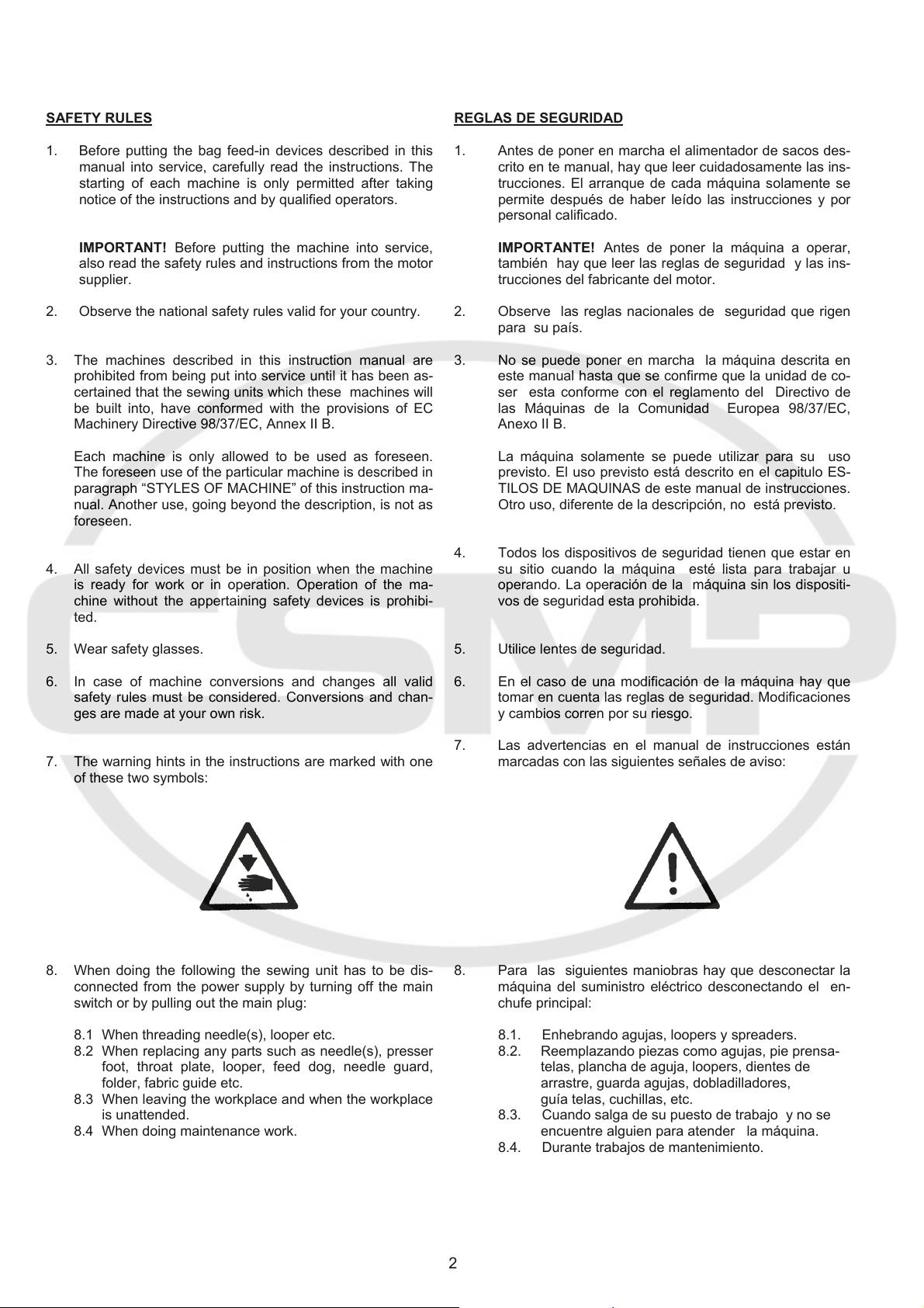
7. The warning hints in the instructions are marked with one
of these two symbols:
8. When doing the following the sewing unit has to be dis-
connected from the power supply by turning off the main
switch or by pulling out the main plug:
8.1 When threading needle(s), looper etc.
8.2 When replacing any parts such as needle(s), presser
foot, throat plate, looper, feed dog, needle guard,
folder, fabric guide etc.
8.3 When leaving the workplace and when the workplace
is unattended.
8.4 When doing maintenance work.
1. Antes de poner en marcha el alimentador de sacos des-
crito en te manual, hay que leer cuidadosamente las ins-
trucciones. El arranque de cada máquina solamente se
permite después de haber leído las instrucciones y por
personal calificado.
IMPORTANTE! Antes de poner la máquina a operar,
también hay que leer las reglas de seguridad y las ins-
trucciones del fabricante del motor.
2. Observe las reglas nacionales de seguridad que rigen
para su país.
3. No se puede poner en marcha la máquina descrita en
este manual hasta que se confirme que la unidad de co-
ser esta conforme con el reglamento del Directivo de
las Máquinas de la Comunidad Europea 98/37/EC,
Anexo II B.
La máquina solamente se puede utilizar para su uso
previsto. El uso previsto está descrito en el capitulo ES-
TILOS DE MAQUINAS de este manual de instrucciones.
Otro uso, diferente de la descripción, no está previsto.
4. Todos los dispositivos de seguridad tienen que estar en
su sitio cuando la máquina esté lista para trabajar u
operando. La operación de la máquina sin los dispositi-
vos de seguridad esta prohibida.
5. Utilice lentes de seguridad.
6. En el caso de una modificación de la máquina hay que
tomar en cuenta las reglas de seguridad. Modificaciones
y cambios corren por su riesgo.
7. Las advertencias en el manual de instrucciones están
marcadas con las siguientes señales de aviso:
8. Para las siguientes maniobras hay que desconectar la
máquina del suministro eléctrico desconectando el en-
chufe principal:
8.1. Enhebrando agujas, loopers y spreaders.
8.2. Reemplazando piezas como agujas, pie prensa-
telas, plancha de aguja, loopers, dientes de
arrastre, guarda agujas, dobladilladores,
guía telas, cuchillas, etc.
8.3. Cuando salga de su puesto de trabajo y no se
encuentre alguien para atender la máquina.
8.4. Durante trabajos de mantenimiento.
2
9. Maintenance, repair and conversion work (see item 8)
must be done only by trained technicians or specially skil-
led personnel under consideration of the instructions.
Only genuine spare parts approved by UNION SPECIAL
have to be used for repair. These parts are designed
specifically for your machine and manufactured with ut-
most precision to assure long lasting service.
10. Any work on the electrical equipment must be done by an
electrician or under direction and supervision of specially
skilled personnel.
11. Work on parts and equipment under electrical power is
not permitted. Permissible exceptions are described in
the applicable section of standard sheet EN 50110 / VDE
0105.
12. Before doing maintenance and repair work on the pneu-
matic equipment, the machine has to be disconnected
from the compressed air supply. In case of existing resi-
dual air pressure after disconnecting from compressed
air supply (i.e. pneumatic equipment with air tank), the
pressure has to be removed by bleeding.
9. Mantenimiento, reparaciones y trabajos de conversión
(véase No. 8) solamente pueden ser efectuados por téc-
nicos entrenados o personal especializado bajo conside-
ración de las instrucciones.
Solamente repuestos originales y aprobados por UNION
SPECIAL pueden ser utilizados para reparaciones. Estos
repuestos han sido diseñados específicamente para es-
tas máquinas, con precisión y para asegurar su máxima
vida útil
10. Cualquier trabajo con equipo eléctrico tiene que ser ejecu-
tado por un electricista o bajo la supervisión de personal
especialmente entrenado.
11. No está permitido trabajar en piezas y equipos con la
electricidad conectada. Excepciones permitidas están
descritas en EN 50110 / VDE 0105.
12. Antes de hacer mantenimiento o reparaciones del equipo
neumático, hay que desconectar la máquina de la ali-
mentación del aire comprimido. En el caso que exista
una presión de aire residual después de desconectar la
máquina (por ejemplo equipos con tanques de aire), la
presión tiene que ser eliminada abriendo las válvulas.
STYLES OF MACHINES
BAG FEED-IN DEVICES
for feeding bags and sacks into bag closing machines.
Special conveying chains to protect the bag material.
Standard voltage for motors: 220-240, 380-415 V,
3 phase, 50 Hz / 243-277, 420-480 V, 3 phase, 60 Hz.
Degree of protection: IP 55. Insulation class F.
Painting: RAL 9002, powder coated.
Delivery includes pre-feeler switch 29926A to start the
sewing machine.
Other voltages and frequencies on request.
ESTILOS DE MAQUINAS
ALIMENTADOR DE SACOS
Para alimentar sacos en máquinas cerradoras de sacos.
Cadenas continuas especialmente diseñadas para proteger
el material del saco.
Voltaje estándar del motor: 220-240, 380-415 V,
trifásico, 50 Hz / 243-277, 420-480 V, trifásico, 60 Hz.
Grado de protección: IP 55. Insolación clase F.
Pintura: RAL 9002, cubierta pulverizada.
Envío incluye interruptor del pre palpador 29926A para
arranque de la máquina de coser.
Otras frecuencias y voltajes disponibles contra pedido.
3
TYPES OF BAG CLOSURES / TIPOS DE CERRADO DE SACOS
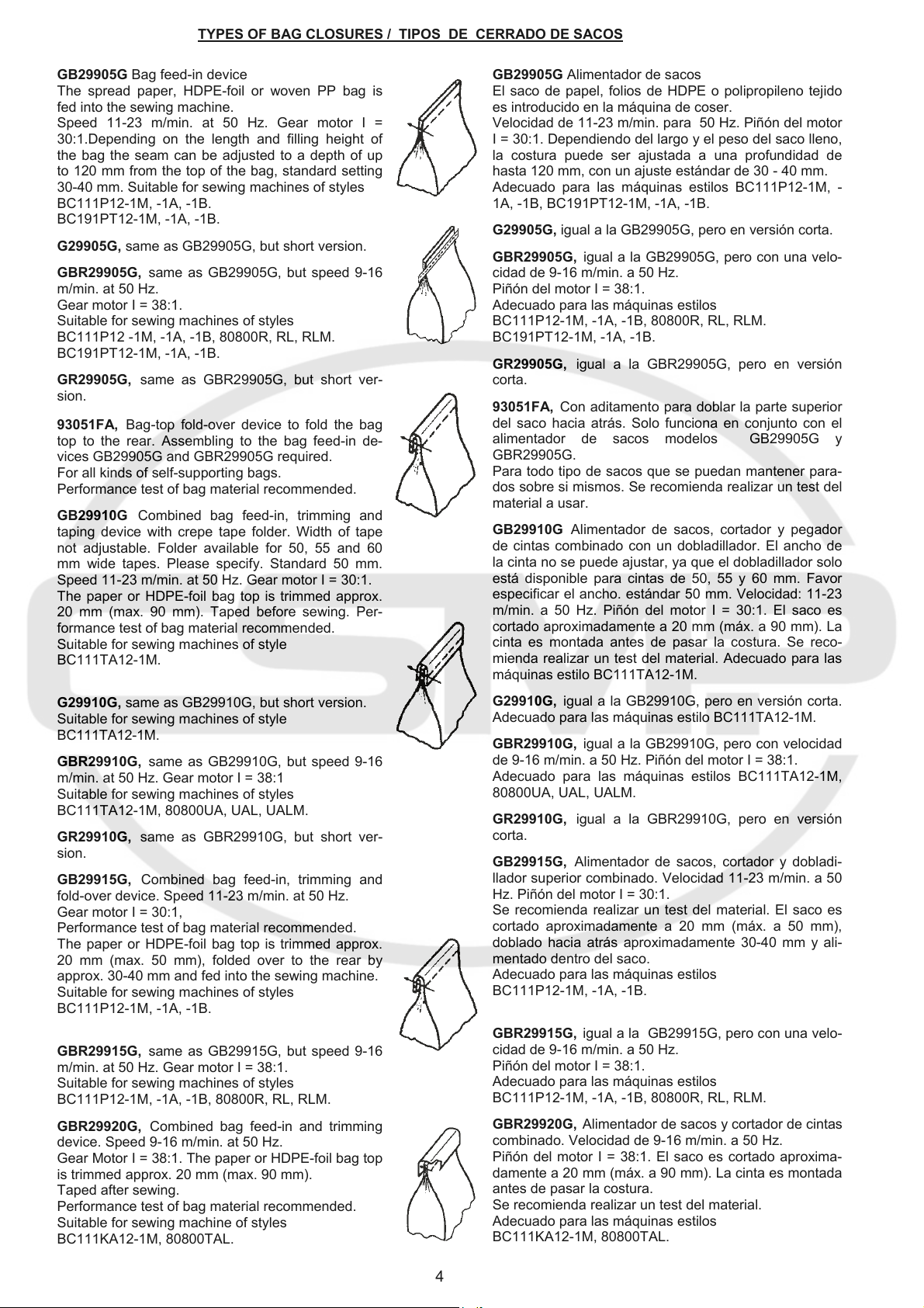
GB29905G Bag feed-in device
The spread paper, HDPE-foil or woven PP bag is
fed into the sewing machine.
Speed 11-23 m/min. at 50 Hz. Gear motor I =
30:1.Depending on the length and filling height of
the bag the seam can be adjusted to a depth of up
to 120 mm from the top of the bag, standard setting
30-40 mm. Suitable for sewing machines of styles
BC111P12-1M, -1A, -1B.
BC191PT12-1M, -1A, -1B.
G29905G, same as GB29905G, but short version.
GBR29905G, same as GB29905G, but speed 9-16
m/min. at 50 Hz.
Gear motor I = 38:1.
Suitable for sewing machines of styles
BC111P12 -1M, -1A, -1B, 80800R, RL, RLM.
BC191PT12-1M, -1A, -1B.
GR29905G, same as GBR29905G, but short ver-
sion.
93051FA, Bag-top fold-over device to fold the bag
top to the rear. Assembling to the bag feed-in de-
vices GB29905G and GBR29905G required.
For all kinds of self-supporting bags.
Performance test of bag material recommended.
GB29910G Combined bag feed-in, trimming and
taping device with crepe tape folder. Width of tape
not adjustable. Folder available for 50, 55 and 60
mm wide tapes. Please specify. Standard 50 mm.
Speed 11-23 m/min. at 50 Hz. Gear motor I = 30:1.
The paper or HDPE-foil bag top is trimmed approx.
20 mm (max. 90 mm). Taped before sewing. Per-
formance test of bag material recommended.
Suitable for sewing machines of style
BC111TA12-1M.
G29910G, same as GB29910G, but short version.
Suitable for sewing machines of style
BC111TA12-1M.
GBR29910G, same as GB29910G, but speed 9-16
m/min. at 50 Hz. Gear motor I = 38:1
Suitable for sewing machines of styles
BC111TA12-1M, 80800UA, UAL, UALM.
GR29910G, same as GBR29910G, but short ver-
sion.
GB29915G, Combined bag feed-in, trimming and
fold-over device. Speed 11-23 m/min. at 50 Hz.
Gear motor I = 30:1,
Performance test of bag material recommended.
The paper or HDPE-foil bag top is trimmed approx.
20 mm (max. 50 mm), folded over to the rear by
approx. 30-40 mm and fed into the sewing machine.
Suitable for sewing machines of styles
BC111P12-1M, -1A, -1B.
GBR29915G, same as GB29915G, but speed 9-16
m/min. at 50 Hz. Gear motor I = 38:1.
Suitable for sewing machines of styles
BC111P12-1M, -1A, -1B, 80800R, RL, RLM.
GBR29920G, Combined bag feed-in and trimming
device. Speed 9-16 m/min. at 50 Hz.
Gear Motor I = 38:1. The paper or HDPE-foil bag top
is trimmed approx. 20 mm (max. 90 mm).
Taped after sewing.
Performance test of bag material recommended.
Suitable for sewing machine of styles
BC111KA12-1M, 80800TAL.
GB29905G Alimentador de sacos
El saco de papel, folios de HDPE o polipropileno tejido
es introducido en la máquina de coser.
Velocidad de 11-23 m/min. para 50 Hz. Piñón del motor
I = 30:1. Dependiendo del largo y el peso del saco lleno,
la costura puede ser ajustada a una profundidad de
hasta 120 mm, con un ajuste estándar de 30 - 40 mm.
Adecuado para las máquinas estilos BC111P12-1M, -
1A, -1B, BC191PT12-1M, -1A, -1B.
G29905G, igual a la GB29905G, pero en versión corta.
GBR29905G, igual a la GB29905G, pero con una velo-
cidad de 9-16 m/min. a 50 Hz.
Piñón del motor I = 38:1.
Adecuado para las máquinas estilos
BC111P12-1M, -1A, -1B, 80800R, RL, RLM.
BC191PT12-1M, -1A, -1B.
GR29905G, igual a la GBR29905G, pero en versión
corta.
93051FA, Con aditamento para doblar la parte superior
del saco hacia atrás. Solo funciona en conjunto con el
alimentador de sacos modelos GB29905G y
GBR29905G.
Para todo tipo de sacos que se puedan mantener para-
dos sobre si mismos. Se recomienda realizar un test del
material a usar.
GB29910G Alimentador de sacos, cortador y pegador
de cintas combinado con un dobladillador. El ancho de
la cinta no se puede ajustar, ya que el dobladillador solo
está disponible para cintas de 50, 55 y 60 mm. Favor
especificar el ancho. estándar 50 mm. Velocidad: 11-23
m/min. a 50 Hz. Piñón del motor I = 30:1. El saco es
cortado aproximadamente a 20 mm (máx. a 90 mm). La
cinta es montada antes de pasar la costura. Se reco-
mienda realizar un test del material. Adecuado para las
máquinas estilo BC111TA12-1M.
G29910G, igual a la GB29910G, pero en versión corta.
Adecuado para las máquinas estilo BC111TA12-1M.
GBR29910G, igual a la GB29910G, pero con velocidad
de 9-16 m/min. a 50 Hz. Piñón del motor I = 38:1.
Adecuado para las máquinas estilos BC111TA12-1M,
80800UA, UAL, UALM.
GR29910G, igual a la GBR29910G, pero en versión
corta.
GB29915G, Alimentador de sacos, cortador y dobladi-
llador superior combinado. Velocidad 11-23 m/min. a 50
Hz. Piñón del motor I = 30:1.
Se recomienda realizar un test del material. El saco es
cortado aproximadamente a 20 mm (máx. a 50 mm),
doblado hacia atrás aproximadamente 30-40 mm y ali-
mentado dentro del saco.
Adecuado para las máquinas estilos
BC111P12-1M, -1A, -1B.
GBR29915G, igual a la GB29915G, pero con una velo-
cidad de 9-16 m/min. a 50 Hz.
Piñón del motor I = 38:1.
Adecuado para las máquinas estilos
BC111P12-1M, -1A, -1B, 80800R, RL, RLM.
GBR29920G, Alimentador de sacos y cortador de cintas
combinado. Velocidad de 9-16 m/min. a 50 Hz.
Piñón del motor I = 38:1. El saco es cortado aproxima-
damente a 20 mm (máx. a 90 mm). La cinta es montada
antes de pasar la costura.
Se recomienda realizar un test del material.
Adecuado para las máquinas estilos
BC111KA12-1M, 80800TAL.
4
MAINTENANCE
When sacking flour, salt, aggressive fertilizers, chemi-
cals, etc. the feeding chains of the bag feed-in device
have to be cleaned and lubricated daily to prevent cor-
rosion.
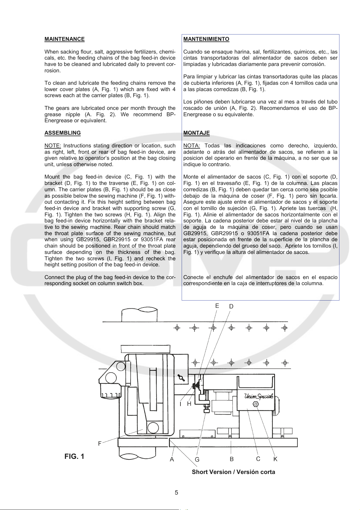
To clean and lubricate the feeding chains remove the
lower cover plates (A, Fig. 1) which are fixed with 4
screws each at the carrier plates (B, Fig. 1).
The gears are lubricated once per month through the
grease nipple (A. Fig. 2). We recommend BP-
Energrease or equivalent.
ASSEMBLING
Instructions stating direction or location, such
NOTE:
as right, left, front or rear of bag feed-in device, are
given relative to operator’s position at the bag closing
unit, unless otherwise noted.
Mount the bag feed-in device (C, Fig. 1) with the
bracket (D, Fig. 1) to the traverse (E, Fig. 1) on col-
umn. The carrier plates (B, Fig. 1) should be as close
as possible below the sewing machine (F, Fig. 1) with-
out contacting it. Fix this height setting between bag
feed-in device and bracket with supporting screw (G,
Fig. 1). Tighten the two screws (H, Fig. 1). Align the
bag feed-in device horizontally with the bracket rela-
tive to the sewing machine. Rear chain should match
the throat plate surface of the sewing machine, but
when using GB29915, GBR29915 or 93051FA rear
chain should be positioned in front of the throat plate
surface depending on the thickness of the bag.
Tighten the two screws (I, Fig. 1) and recheck the
height setting position of the bag feed-in device.
Connect the plug of the bag feed-in device to the cor-
responding socket on column switch box.
MANTENIMIENTO
Cuando se ensaque harina, sal, fertilizantes, quimicos, etc., las
cintas transportadoras del alimentador de sacos deben ser
limpiadas y lubricadas diariamente para prevenir corrosión.
Para limpiar y lubricar las cintas transortadoras quite las placas
de cubierta inferiores (A, Fig. 1), fijadas con 4 tornillos cada una
a las placas corredizas (B, Fig. 1).
Los piñones deben lubricarse una vez al mes a través del tubo
roscado de unión (A, Fig. 2). Recomendamos el uso de BP-
Energrease o su equivalente.
MONTAJE
NOTA:
adelante o atrás del alimentador de sacos, se refieren a la
posicion del operario en frente de la máquina, a no ser que se
indique lo contrario.
Monte el alimentador de sacos (C, Fig. 1) con el soporte (D,
Fig. 1) en el travesaño (E, Fig. 1) de la columna. Las placas
corredizas (B, Fig. 1) deben quedar tan cerca como sea psoible
debajo de la máquina de coser (F, Fig. 1) pero sin tocarla.
Asegure este ajuste entre el alimentador de sacos y el soporte
con el tornillo de sujeción (G, Fig. 1). Apriete las tuercas (H,
Fig. 1). Alinie el alimentador de sacos horizontalmente con el
soporte. La cadena posterior debe estar al nivel de la plancha
de aguja de la máquina de coser, pero cuando se usan
GB29915, GBR29915 o 93051FA la cadena posterior debe
estar posicionada en frente de la superficie de la plancha de
aguja, dependiendo del grueso del saco. Apriete los tornillos (I,
Fig. 1) y verifique la altura del alimentador de sacos.
Conecte el enchufe del alimentador de sacos en el espacio
correspondiente en la caja de interruptores de la columna.
Todas las indicaciones como derecho, izquierdo,
FIG. 1
Short Version / Versión corta
5
SYNCHRONIZING THE FEED-IN SPEED WITH THE
CONVEYOR SPEED
The feed-in speed of the bag feed-in device is infinitely
adjustable from 11 to 23 m/min. resp. 9 to 16 m/min. at
50 Hz and 13 to 27 m/min. resp. 10 to 19 m/min. at 60
Hz. Within this range it can be matched with each con-
veyor speed.
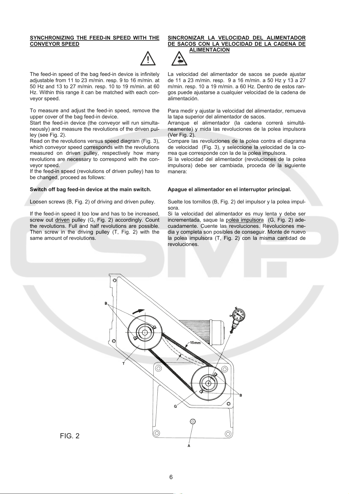
To measure and adjust the feed-in speed, remove the
upper cover of the bag feed-in device.
Start the feed-in device (the conveyor will run simulta-
neously) and measure the revolutions of the driven pul-
ley (see Fig. 2).
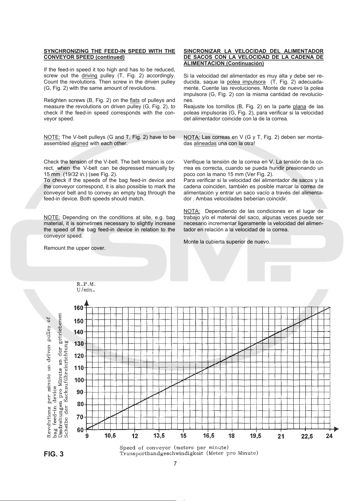
Read on the revolutions versus speed diagram (Fig. 3),
which conveyor speed corresponds with the revolutions
measured on driven pulley, respectively how many
revolutions are necessary to correspond with the con-
veyor speed.
If the feed-in speed (revolutions of driven pulley) has to
be changed, proceed as follows:
Switch off bag feed-in device at the main switch.
Loosen screws (B, Fig. 2) of driving and driven pulley.
If the feed-in speed it too low and has to be increased,
screw out driven
the revolutions. Full and half revolutions are possible.
Then screw in the driving pulley (T, Fig. 2) with the
same amount of revolutions.
pulley (G, Fig. 2) accordingly. Count
SINCRONIZAR LA VELOCIDAD DEL ALIMENTADOR
DE SACOS CON LA VELOCIDAD DE LA CADENA DE
ALIMENTACION
La velocidad del alimentador de sacos se puede ajustar
de 11 a 23 m/min. resp. 9 a 16 m/min. a 50 Hz y 13 a 27
m/min. resp. 10 a 19 m/min. a 60 Hz. Dentro de estos ran-
gos puede ajustarse a cualquier velocidad de la cadena de
alimentación.
Para medir y ajustar la velocidad del alimentador, remueva
la tapa superior del alimentador de sacos.
Arranque el alimentador (la cadena correrá simultá-
neamente) y mida las revoluciones de la polea impulsora
(Ver Fig. 2).
Compare las revoluciones de la polea contra el diagrama
de velocidad (Fig. 3), y seleccione la velocidad de la co-
rrea que corresponde con la de la polea impulsora.
Si la velocidad del alimentador (revoluciones de la polea
impulsora) debe ser cambiada, proceda de la siguiente
manera:
Apague el alimentador en el interruptor principal.
Suelte los tornillos (B, Fig. 2) del impulsor y la polea impul-
sora.
Si la velocidad del alimentador es muy lenta y debe ser
incrementada, saque la polea impulsora
cuadamente. Cuente las revoluciones. Revoluciones me-
dia y completa son posibles de conseguir. Monte de nuevo
la polea impulsora (T, Fig. 2) con la misma cantidad de
revoluciones.
(G, Fig. 2) ade-
FIG. 2
6
SYNCHRONIZING THE FEED-IN SPEED WITH THE
CONVEYOR SPEED (continued)
If the feed-in speed it too high and has to be reduced,
screw out the driving
Count the revolutions. Then screw in the driven pulley
(G, Fig. 2) with the same amount of revolutions.
Retighten screws (B, Fig. 2) on the flats of pulleys and
measure the revolutions on driven pulley (G, Fig. 2), to
check if the feed-in speed corresponds with the con-
veyor speed.
NOTE: The V-belt pulleys (G and T, Fig. 2) have to be
assembled aligned
Check the tension of the V-belt. The belt tension is cor-
rect, when the V-belt can be depressed manually by
15 mm (19/32 in.) (see Fig. 2).
To check if the speeds of the bag feed-in device and
the conveyor correspond, it is also possible to mark the
conveyor belt and to convey an empty bag through the
feed-in device. Both speeds should match.
NOTE: Depending on the conditions at site, e.g. bag
material, it is sometimes necessary to slightly increase
the speed of the bag feed-in device in relation to the
conveyor speed.
Remount the upper cover.
pulley (T, Fig. 2) accordingly.
with each other.
SINCRONIZAR LA VELOCIDAD DEL ALIMENTADOR
DE SACOS CON LA VELOCIDAD DE LA CADENA DE
ALIMENTACION (Continuación)
Si la velocidad del alimentador es muy alta y debe ser re-
ducida, saque la polea impulsora (T, Fig. 2) adecuada-
mente. Cuente las revoluciones. Monte de nuevo la polea
impulsora (G, Fig. 2) con la misma cantidad de revolucio-
nes.
Reajuste los tornillos (B, Fig. 2) en la parte plana de las
poleas impulsoras (G, Fig. 2), para verificar si la velocidad
del alimentador coincide con la de la correa.
Las correas en V (G y T, Fig. 2) deben ser monta-
NOTA:
das alineadas
Verifique la tensión de la correa en V. La tensión de la co-
rrea es correcta, cuando se pueda hundir presionando un
poco con la mano 15 mm (Ver Fig. 2).
Para verificar si la velocidad del alimentador de sacos y la
cadena coinciden, también es posible marcar la correa de
alimentación y entrar un saco vacío a través del alimenta-
dor . Ambas velocidades beberían coincidir.
NOTA:
trabajo y/o el material del saco, algunas veces puede ser
necesario incrementar ligeramente la velocidad del alimen-
tador en relación a la velocidad de la correa.
Monte la cubierta superior de nuevo.
una con la otra!
Dependiendo de las condiciones en el lugar de
FIG. 3
7

TIGHTENING AND ADJUSTING THE CHAINS
Switch off bag feed-in device at the
main switch!
Remove the two lower chain covers (A, Fig. 1). Mount
the two chains so, that the chain links are offset to each
other and the gaps between the chain links are posi-
tioned approx. within the center of the chain links of the
opposite chain (A, Fig. 4).
After loosening the two nuts (B, Fig. 4) on the top of
carrier plates and the nuts (L and R, Fig. 4) the chains
can be tightened with threaded bolts (D, Fig. 4). Cau-
tion, nuts (L, Fig. 4) have a left hand thread. the chains
should be tightened just so, that they can be depressed
manually by 8 to 10 mm (5/16 to 25/64 in.) (see Fig.
4A).
NOTE:
Do not over tighten chains. This may cause
chain breaking as well a damages on the carrier plates
and the motor.
The chain adjusters have to be mounted offset to each
other (see X, Fig. 4). Retighten nuts (B, L and R, Fig.
4).
The chain guides (G and H, Fig. 4A) are adjustable af-
ter loosening screws (J, Fig. 4A) Set the two inner
chain guides (G, Fig. 4A) parallel to each other and so
that the chains are not pushed away from the sprockets
(E, Fig. 4A). The sprockets must engage fully between
the rolls of the chain links.
Set the two outer chain guides (H, Fig. 4A), without
presser, parallel and close to the chains. Retighten
screws (J, Fig. 4A) and mount the covers.
APRETADO Y AJUSTE DE LAS CADENAS
Apague el alimentador en el interruptor
principal!
Desmonte las dos cubiertas inferiores de las cadenas (A,
Fig. 1). Monte las cadenas de manera tal que los dientes
de la cadena queden uno frente al otro y las separaciones
entre los dientes estén posicionadas aproximadamente
dentro del centro de los dientes de la cadena opuesta (A,
Fig. 4).
Después de aflojar las dos tuerca (B, Fig. 4) en la parte
superior de la plancha transportadora y las tuercas (L y R,
Fig. 4), las cadenas pueden ser apretadas con los pernos
de ajuste (D, Fig. 4). Cuidado, las tuercas (L, Fig. 4) enros-
can a la izquierda. Las cadenas deben ser ajustadas de
manera tal que al ser presionadas con la mano, se undir
de 8 a 10 mm (Ver Fig. 4A).
NOTA:
No apriete demasiado las cadenas. Esto puede
causar rotura de la cadena y daños en las planchas trans-
portadoras y el motor.
Los ajustadores de las cadenas deben ser montados de
manera tal que queden uno frente al otro (Ver X, Fig. 4).
Apriete las tuercas (B, L y R, Fig. 4).
Las guías de las cadenas (G y H, Fig. 4A) pueden ser
ajustadas después de soltar los tornillos (J, Fig. 4A). Colo-
que las dos guías internas de las cadenas (G, Fig. 4A) pa-
ralelamente una a la otra de manera que las cadenas no
se salgan de los piñones (E, Fig. 4A). Los eslabones de
las cadenas deben encajar perfectamente en los piñones.
Ajuste las guías de las cadenas externas (H, Fig. 4A) sin
presión, paralelas y cerca a las cadenas. Apriete los torni-
llos (J, Fig. 4A) y monte nuevamente las cubiertas.
FIG. 4
ADJUSTING THE CHAIN PRESSURE
The presser of the front roller chain can be adjusted
with stop screw and lock nut (K, Fig. 1). The stop screw
is normally set so, that the chain in the front spring
loaded chain case just contacts the rear chain, without
exerting any pressure on it. Depending on the type and
thickness of the bag material, this setting sometimes
has to be changed slightly.
FIG. 4A
AJUSTE DE LA PRESION DE LA CADENA
La presión de la cadena frontal puede ser ajustada con el
tornillo tope y la contra tuerca (K, Fig. 1). El tornillo tope
normalmente esta ajustado de manera tal que la cadena
en el resorte frontal de la caja toca la cadena posterior
ligeramente, sin ejercer ninguna presión. Dependiendo
del tipo y grosor del material del saco a cerrar, este ajuste
debe cambiarse.
8
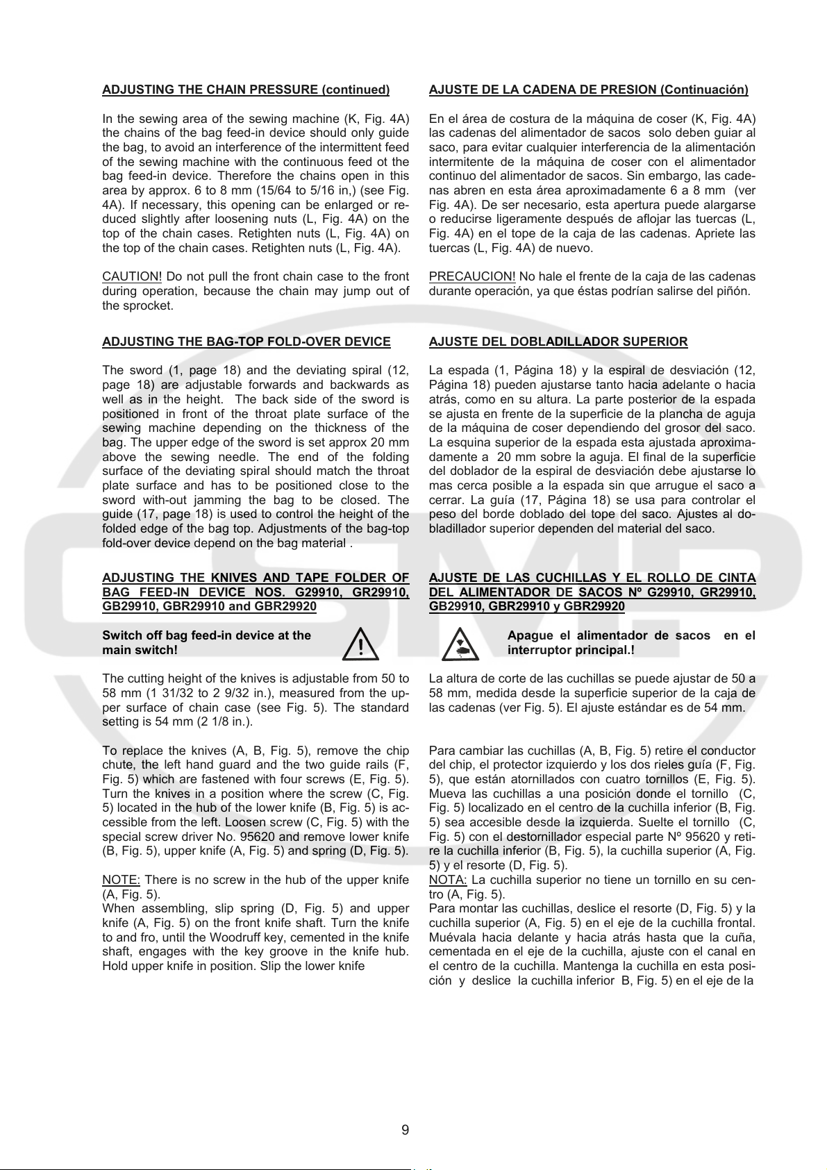
ADJUSTING THE CHAIN PRESSURE (continued)
In the sewing area of the sewing machine (K, Fig. 4A)
the chains of the bag feed-in device should only guide
the bag, to avoid an interference of the intermittent feed
of the sewing machine with the continuous feed ot the
bag feed-in device. Therefore the chains open in this
area by approx. 6 to 8 mm (15/64 to 5/16 in,) (see Fig.
4A). If necessary, this opening can be enlarged or re-
duced slightly after loosening nuts (L, Fig. 4A) on the
top of the chain cases. Retighten nuts (L, Fig. 4A) on
the top of the chain cases. Retighten nuts (L, Fig. 4A).
CAUTION!
during operation, because the chain may jump out of
the sprocket.
Do not pull the front chain case to the front
AJUSTE DE LA CADENA DE PRESION (Continuación)
En el área de costura de la máquina de coser (K, Fig. 4A)
las cadenas del alimentador de sacos solo deben guiar al
saco, para evitar cualquier interferencia de la alimentación
intermitente de la máquina de coser con el alimentador
continuo del alimentador de sacos. Sin embargo, las cade-
nas abren en esta área aproximadamente 6 a 8 mm (ver
Fig. 4A). De ser necesario, esta apertura puede alargarse
o reducirse ligeramente después de aflojar las tuercas (L,
Fig. 4A) en el tope de la caja de las cadenas. Apriete las
tuercas (L, Fig. 4A) de nuevo.
PRECAUCION!
durante operación, ya que éstas podrían salirse del piñón.
No hale el frente de la caja de las cadenas
ADJUSTING THE BAG-TOP FOLD-OVER DEVICE
The sword (1, page 18) and the deviating spiral (12,
page 18) are adjustable forwards and backwards as
well as in the height. The back side of the sword is
positioned in front of the throat plate surface of the
sewing machine depending on the thickness of the
bag. The upper edge of the sword is set approx 20 mm
above the sewing needle. The end of the folding
surface of the deviating spiral should match the throat
plate surface and has to be positioned close to the
sword with-out jamming the bag to be closed. The
guide (17, page 18) is used to control the height of the
folded edge of the bag top. Adjustments of the bag-top
fold-over device depend on the bag material .
ADJUSTING THE KNIVES AND TAPE FOLDER OF
BAG FEED-IN DEVICE NOS. G29910, GR29910,
GB29910, GBR29910 and GBR29920
Switch off bag feed-in device at the
main switch!
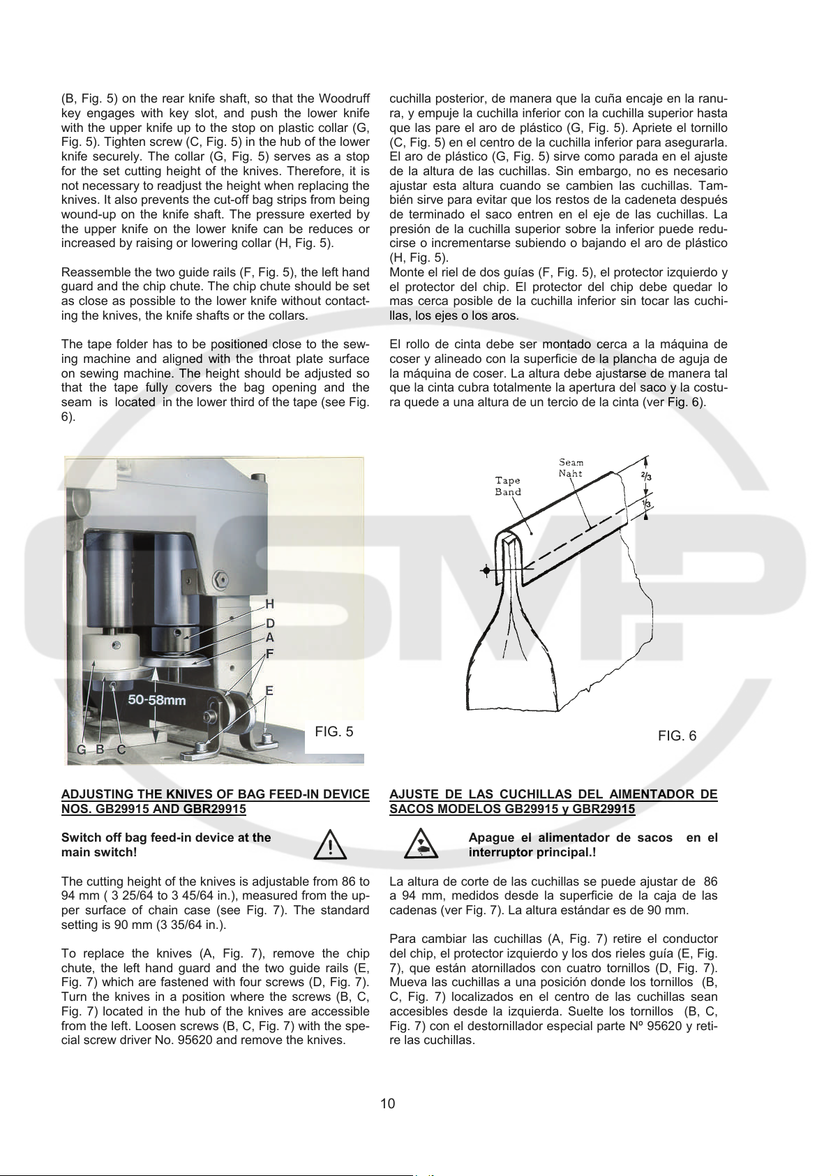
The cutting height of the knives is adjustable from 50 to
58 mm (1 31/32 to 2 9/32 in.), measured from the up-
per surface of chain case (see Fig. 5). The standard
setting is 54 mm (2 1/8 in.).
To replace the knives (A, B, Fig. 5), remove the chip
chute, the left hand guard and the two guide rails (F,
Fig. 5) which are fastened with four screws (E, Fig. 5).
Turn the knives in a position where the screw (C, Fig.
5) located in the hub of the lower knife (B, Fig. 5) is ac-
cessible from the left. Loosen screw (C, Fig. 5) with the
special screw driver No. 95620 and remove lower knife
(B, Fig. 5), upper knife (A, Fig. 5) and spring (D, Fig. 5).
NOTE:
There is no screw in the hub of the upper knife
(A, Fig. 5).
When assembling, slip spring (D, Fig. 5) and upper
knife (A, Fig. 5) on the front knife shaft. Turn the knife
to and fro, until the Woodruff key, cemented in the knife
shaft, engages with the key groove in the knife hub.
Hold upper knife in position. Slip the lower knife
AJUSTE DEL DOBLADILLADOR SUPERIOR
La espada (1, Página 18) y la espiral de desviación (12,
Página 18) pueden ajustarse tanto hacia adelante o hacia
atrás, como en su altura. La parte posterior de la espada
se ajusta en frente de la superficie de la plancha de aguja
de la máquina de coser dependiendo del grosor del saco.
La esquina superior de la espada esta ajustada aproxima-
damente a 20 mm sobre la aguja. El final de la superficie
del doblador de la espiral de desviación debe ajustarse lo
mas cerca posible a la espada sin que arrugue el saco a
cerrar. La guía (17, Página 18) se usa para controlar el
peso del borde doblado del tope del saco. Ajustes al do-
bladillador superior dependen del material del saco.
AJUSTE DE LAS CUCHILLAS Y EL ROLLO DE CINTA
DEL ALIMENTADOR DE SACOS Nº G29910, GR29910,
GB29910, GBR29910 y GBR29920
Apague el alimentador de sacos en el
interruptor principal.!
La altura de corte de las cuchillas se puede ajustar de 50 a
58 mm, medida desde la superficie superior de la caja de
las cadenas (ver Fig. 5). El ajuste estándar es de 54 mm.
Para cambiar las cuchillas (A, B, Fig. 5) retire el conductor
del chip, el protector izquierdo y los dos rieles guía (F, Fig.
5), que están atornillados con cuatro tornillos (E, Fig. 5).
Mueva las cuchillas a una posición donde el tornillo (C,
Fig. 5) localizado en el centro de la cuchilla inferior (B, Fig.
5) sea accesible desde la izquierda. Suelte el tornillo (C,
Fig. 5) con el destornillador especial parte Nº 95620 y reti-
re la cuchilla inferior (B, Fig. 5), la cuchilla superior (A, Fig.
5) y el resorte (D, Fig. 5).
La cuchilla superior no tiene un tornillo en su cen-
NOTA:
tro (A, Fig. 5).
Para montar las cuchillas, deslice el resorte (D, Fig. 5) y la
cuchilla superior (A, Fig. 5) en el eje de la cuchilla frontal.
Muévala hacia delante y hacia atrás hasta que la cuña,
cementada en el eje de la cuchilla, ajuste con el canal en
el centro de la cuchilla. Mantenga la cuchilla en esta posi-
ción y deslice la cuchilla inferior B, Fig. 5) en el eje de la
9
(B, Fig. 5) on the rear knife shaft, so that the Woodruff
key engages with key slot, and push the lower knife
with the upper knife up to the stop on plastic collar (G,
Fig. 5). Tighten screw (C, Fig. 5) in the hub of the lower
knife securely. The collar (G, Fig. 5) serves as a stop
for the set cutting height of the knives. Therefore, it is
not necessary to readjust the height when replacing the
knives. It also prevents the cut-off bag strips from being
wound-up on the knife shaft. The pressure exerted by
the upper knife on the lower knife can be reduces or
increased by raising or lowering collar (H, Fig. 5).
Reassemble the two guide rails (F, Fig. 5), the left hand
guard and the chip chute. The chip chute should be set
as close as possible to the lower knife without contact-
ing the knives, the knife shafts or the collars.
The tape folder has to be positioned close to the sew-
ing machine and aligned with the throat plate surface
on sewing machine. The height should be adjusted so
that the tape fully covers the bag opening and the
seam is located in the lower third of the tape (see Fig.
6).
cuchilla posterior, de manera que la cuña encaje en la ranu-
ra, y empuje la cuchilla inferior con la cuchilla superior hasta
que las pare el aro de plástico (G, Fig. 5). Apriete el tornillo
(C, Fig. 5) en el centro de la cuchilla inferior para asegurarla.
El aro de plástico (G, Fig. 5) sirve como parada en el ajuste
de la altura de las cuchillas. Sin embargo, no es necesario
ajustar esta altura cuando se cambien las cuchillas. Tam-
bién sirve para evitar que los restos de la cadeneta después
de terminado el saco entren en el eje de las cuchillas. La
presión de la cuchilla superior sobre la inferior puede redu-
cirse o incrementarse subiendo o bajando el aro de plástico
(H, Fig. 5).
Monte el riel de dos guías (F, Fig. 5), el protector izquierdo y
el protector del chip. El protector del chip debe quedar lo
mas cerca posible de la cuchilla inferior sin tocar las cuchi-
llas, los ejes o los aros.
El rollo de cinta debe ser montado cerca a la máquina de
coser y alineado con la superficie de la plancha de aguja de
la máquina de coser. La altura debe ajustarse de manera tal
que la cinta cubra totalmente la apertura del saco y la costu-
ra quede a una altura de un tercio de la cinta (ver Fig. 6).
FIG. 5
ADJUSTING THE KNIVES OF BAG FEED-IN DEVICE
NOS. GB29915 AND GBR29915
Switch off bag feed-in device at the
main switch!
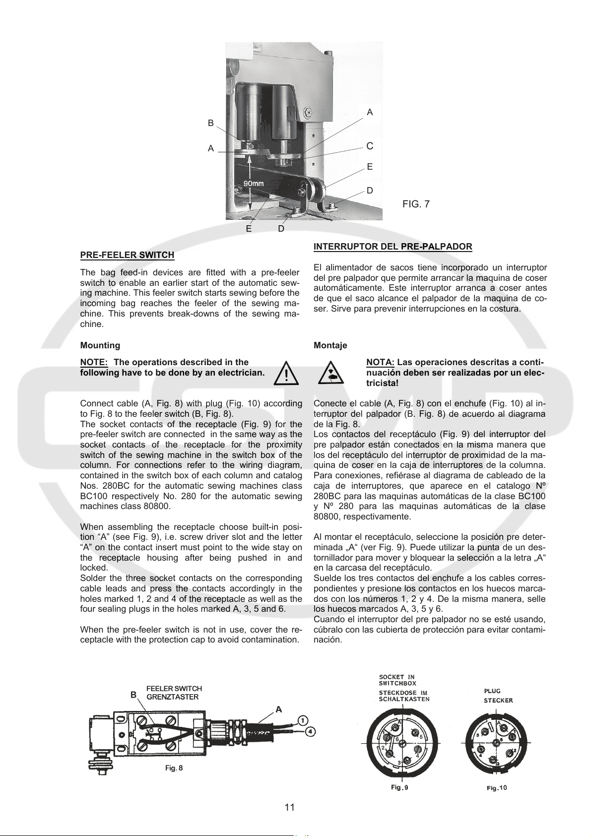
The cutting height of the knives is adjustable from 86 to
94 mm ( 3 25/64 to 3 45/64 in.), measured from the up-
per surface of chain case (see Fig. 7). The standard
setting is 90 mm (3 35/64 in.).
To replace the knives (A, Fig. 7), remove the chip
chute, the left hand guard and the two guide rails (E,
Fig. 7) which are fastened with four screws (D, Fig. 7).
Turn the knives in a position where the screws (B, C,
Fig. 7) located in the hub of the knives are accessible
from the left. Loosen screws (B, C, Fig. 7) with the spe-
cial screw driver No. 95620 and remove the knives.
FIG. 6
AJUSTE DE LAS CUCHILLAS DEL AIMENTADOR DE
SACOS MODELOS GB29915 y GBR29915
Apague el alimentador de sacos en el
interruptor principal.!
La altura de corte de las cuchillas se puede ajustar de 86
a 94 mm, medidos desde la superficie de la caja de las
cadenas (ver Fig. 7). La altura estándar es de 90 mm.
Para cambiar las cuchillas (A, Fig. 7) retire el conductor
del chip, el protector izquierdo y los dos rieles guía (E, Fig.
7), que están atornillados con cuatro tornillos (D, Fig. 7).
Mueva las cuchillas a una posición donde los tornillos (B,
C, Fig. 7) localizados en el centro de las cuchillas sean
accesibles desde la izquierda. Suelte los tornillos (B, C,
Fig. 7) con el destornillador especial parte Nº 95620 y reti-
re las cuchillas.
10
B
A
A
D E
PRE-FEELER SWITCH
The bag feed-in devices are fitted with a pre-feeler
switch to enable an earlier start of the automatic sew-
ing machine. This feeler switch starts sewing before the
incoming bag reaches the feeler of the sewing ma-
chine. This prevents break-downs of the sewing ma-
chine.
Mounting
NOTE: The operations described in the
following have to be done by an electrician.
Connect cable (A, Fig. 8) with plug (Fig. 10) according
to Fig. 8 to the feeler switch (B, Fig. 8).
The socket contacts of the receptacle (Fig. 9) for the
pre-feeler switch are connected in the same way as the
socket contacts of the receptacle for the proximity
switch of the sewing machine in the switch box of the
column. For connections refer to the wiring diagram,
contained in the switch box of each column and catalog
Nos. 280BC for the automatic sewing machines class
BC100 respectively No. 280 for the automatic sewing
machines class 80800.
When assembling the receptacle choose built-in posi-
tion “A” (see Fig. 9), i.e. screw driver slot and the letter
“A” on the contact insert must point to the wide stay on
the receptacle housing after being pushed in and
locked.
Solder the three socket contacts on the corresponding
cable leads and press the contacts accordingly in the
holes marked 1, 2 and 4 of the receptacle as well as the
four sealing plugs in the holes marked A, 3, 5 and 6.
When the pre-feeler switch is not in use, cover the re-
ceptacle with the protection cap to avoid contamination.
C
E
D
FIG. 7
INTERRUPTOR DEL PRE-PALPADOR
El alimentador de sacos tiene incorporado un interruptor
del pre palpador que permite arrancar la maquina de coser
automáticamente. Este interruptor arranca a coser antes
de que el saco alcance el palpador de la maquina de co-
ser. Sirve para prevenir interrupciones en la costura.
Montaje
Conecte el cable (A, Fig. 8) con el enchufe (Fig. 10) al in-
terruptor del palpador (B. Fig. 8) de acuerdo al diagrama
de la Fig. 8.
Los contactos del receptáculo (Fig. 9) del interruptor del
pre palpador están conectados en la misma manera que
los del receptáculo del interruptor de proximidad de la ma-
quina de coser en la caja de interruptores de la columna.
Para conexiones, refiérase al diagrama de cableado de la
caja de interruptores, que aparece en el catalogo Nº
280BC para las maquinas automáticas de la clase BC100
y Nº 280 para las maquinas automáticas de la clase
80800, respectivamente.
Al montar el receptáculo, seleccione la posición pre deter-
minada „A“ (ver Fig. 9). Puede utilizar la punta de un des-
tornillador para mover y bloquear la selección a la letra „A“
en la carcasa del receptáculo.
Suelde los tres contactos del enchufe a los cables corres-
pondientes y presione los contactos en los huecos marca-
dos con los números 1, 2 y 4. De la misma manera, selle
los huecos marcados A, 3, 5 y 6.
Cuando el interruptor del pre palpador no se esté usando,
cúbralo con las cubierta de protección para evitar contami-
nación.
NOTA: Las operaciones descritas a conti-
nuación deben ser realizadas por un elec-
tricista!
11
 Loading...