

Page 1

Page 2

Page 3
CATALOG
NO.
49
Instructions
Installing,
11500
11500
11500
A
F
G
Operating
With
TJNION
General
Representatives
BRANCHES
Hosiim,
T.yiin.
iliivorhill,
New
York,
Ulien,
Koi'hester,
Newark,
Baltimore,
Detroit,
BELGIUM,
CANADA,
CANADA.
DhlNMARK,
ENGLAND,
FRANCE.
PRANCE.
GERMANY,
ARGENTINE
Buenos
AUSTRIA
Vienna
AUSTRALIA
Meliiourne
Sydney
BRAZIL
Rio
De
Santos
CANADA
Winnipeg
CHINA
Hong
Shanghai
CUBA
Havana
DUTCH
Batavia
Mass.
Mass,
N.
Y.
SERVICE
N.
Mich,
Foreign
Aires
Janeiro
Kong
EAST
AND
Miiss,
N.
Y.
N.
Y.
REPRESENTATIVES,
J.
Md.
Brussels
Toronto
Montreal
Copenhagen
Leicester
Paris
Lyons
Stuttgart
Distributors
REPUBLIC
INDIES
Copyright,
Styles
11500
11700
11700
List
SPECIAL
Office:
SERVICE
BRANCHES,
Union
Union
Union
Comiiagnio
Compagiiie
Union
ECUADOR
ENGLAND
PRKNCH
HAWAIIAN
INDIA
IRELAND
ITALY
JAPAN
1923,
MACHINE
400
North
Chicago,
in
all
STATIONS,
Jolitison
Ainsierdiim.
Triiy,
I'liiiiidelphia,
Reiuiing,
Toledo,
Union
Union
City,
N.
Y.
Pii.
Ohio
Nashville,
Atlanta,
Ga.
Milwaukee,
Special
Special
Special
Special
Special
Special
and
Service
Guayaquil
Leeds
London
Manchester
Norwich
INDO
Saigon
Honolulu
Bombay
Belfast
Milan
Osaka
Tokyo
by
Union
Printed
in
for
and
H
C
F
of
Parts
COMPANY
Franklin
Illinois
Manufacturing
N.
N.
Y.
I'li.
Tenn.
Wis.
FOREIGN
Machine
Machine
Machine
Machine
Machine
des
Machines
de.s
Machines
Machiiienfabrik,
CHINA
ISLANDS
Special
U.
S,
UNITED
Y.
UNITED
Corporation
Company
Company
Corporation
Corporation
Stations
Machine
A.
Union
Union
Adjusting
11700
Street
Centers
STATES
Cleveland,
Ciiieinnati,
Miiineitiiolis,
St.
Kiiiisiis
Sun
Ohio
Louis,
Mo.
City,
Francisco,
STATES
Dallas,
Tex.
Seattle,
'Wash.
Los
Angeles,
of
America.
of
Canada,
of
Canada,
of
America.
of
America.
Special
Special
G.
m.
h.
H.
are
found
MEXICO
Mexico
NEW
PHILIPPINE
PORTUGAL
SCOTLAND
RIAM
SOUTH
SPAIN
URUGUAY
City
ZEALAND
All
ckiand
Ohristchurch
Wellington
Manila
Porto
Glasgow
Durulee
Bangkok
AFRICA
Johannesburg
Barcelona
Montevideo
Co.
11700
11700
Ohio
Minn.
Mo.
Cal.
de
de
in;
ISLANDS
Cal.
Ltd.
Ltd.
France,
Prance.
G
L
M
J
Page 4
IMPORTANT
Tlie
parts
furnished
Attention
that
many
patents,
tions,
at
repairing
their
and
list
prices,
original
or
machines
CUSTOMERS
listed
at
list
prices
is
hereby
of
said
enter
that
in
we
license
condition.
NOTICE
in
tliis
for
called
parts
are
into
i)atented
furnishing
tlielr
of
our
own
TO
catalog
repairs
to
only.
the
subjects
combina
tiiese
parts
use
only
make,
are
fact
of
for
in
Notice
such
thereof
one
than
fringement,
will
is
hereby
parts
by
for
ciiaiiging
style
to
bona fide
for
be
liable
giveii
the
purchaser,
over
another,
repair
to
purposes,
which
the
prosecution.
that
machines
or
for
seller
the
or
any
is
sale
the
from
other
an
or
user
of
use
in
Page 5

CONTENTS
Important
Notice
Foreword
Application
Identification
Illustration
of
of
of
Machines,
Installing
Operating
Oiling
Threading
Adjusting
Formation
Regulating
Tensions
Thread
Repairing
Assembling
Needles
Ordering
Plates
List
of
Repair
Parts
of
Stitch
Length
to
Customers
Catalog
Machines
Ready
of
Stitch
Parts
to
Operate
Page
2
4
5
6
8
H
I7
17
Ig
22
22
27
28
28
31
32
33
35
36
52
Page 6
It
is
Union
that
this
tions
machines
and
Special
will
book
for
definitions.
the
aim
of
tlie
Sewing
secure
is
installing,
in
the
maximum
dedicated.
operating,
Classes
11500
FOREWORD
manaj^ement
Machines
quality
On
the
pages
adjusting
and
11700
to
place
carefully
and
which
witii
prepared
production.
follow
and
repairing
illustrations
before
are
given
the
u.sers
of
information
To
this
end
instruc
the
styles
of
of
the
parts
Detailed
in
Catalog
Catalog
No.
There
mation
which
outs,
efficient
the
users
of
those
relating
sewing
correct
equipment,
Conij)any
of
its
In
all
the
Union
who
information
No.
29.
45.
These
is
also
available a comprehensive
to
the
machines
sejiuence
relating
Needles
books
manufacture
can
of
production
])laces
machines
manufacturing
Special
desire
at
alike
Machine
in
planning
UNION
the
centers
to
the
are
listed
will
be
furnished
of
every
be
used.
operations,
disposal
without
It
specifications
and
all
of
restriction.
can
now
Company,
and
estimating
SPECIAU
MACPIINE
Department
transmitter
and
fully
gratis
fund
of
kind
of
merchandise
embodies
sewing
as
details.
customers
be
who
This
and
found
representatives
Avill
co-operate
their
requirements.
COMPANY
of
Sales
will
be
found
described
on
request.
valuable
infor
room
to
the
information
prospective
Engineering
in
on
lay
most
with
Page 7

This
catalog
widths
specified
as
specified
for
11500
11500
11500
11500
11500
11500
11700
It
can
the
A
F—I
F—^
G—t
G—i
H
C—4
only
APPLICATION
api)lies
tor
tlie
styles
in
inch
"
"
gauge
be
applied
only
to
styles
Class
11700:
hem
with
styles
of
machines
in
Class
11500
11700
11700
11700
11700
11700
11700
11700
11700
discretion
to
and
C-4i
C—5
C—82
F—5
G—5
L—4J
L—5
M—2
otlier
fitted
in
the
gauge
styles.
for
hem
gauges
Page 8
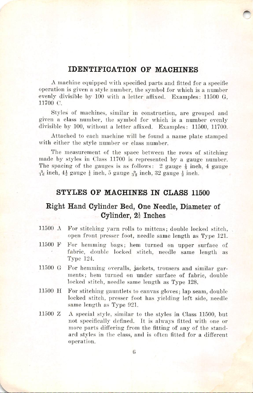
IDENTIFICATION
A
macliiiie
operation
evenly
11700
given a class
divisible
with
made
The
■l\r
inch,
is
given a style
divisible
C.
Styles
of
number,
by
100,
Attached
either
The
by
spacing
to
the
measurement
styles
of
4i
gauge ^ inch, 5 gauge
macliine.s,
e(iuippe<l
witli
specified
nnmber,
by
100
with a letter
similar
tiie
symbol
witlnmt a letter
each
style
niimi)er
in
Class
the
gauges
machine
of
will
or
the
space
11700
is
as
is
OF
MACHINES
parts
and fitted
the
symbol
for
affixed.
in
construction,
for
which
affixed.
be
class
Examples:
found a name
number.
between
the
represented
Examples:
is a number
by a gauge
for a specific
which
is a number
are
grouped
11500,
plate
rows
of
11500
G,
and
evenly
11700.
stamped
stitching
number.
follows: 2 gauge ^ inch, 4 gauge
inch,
32
gauge 4 inch.
STYLES
Right
11500 A For
Hand
open
11500 F For
fabric,
Type
11500 G For
ments;
locked
11500 H For
locked
same
11500 Z A
not
more
ard
operation.
OF
Cylinder
stitching
front
hemming
double
124.
hemming
hem
stitch,
stitching
stitch,
length
special
specifically
parts
styles
MACHINES
Cylinder,
yarn
pi-esser
bags;
locked
<tveralls,
turned
needle
gauntlets
presser
as
Type
style,
similar
defined.
differing
in
tiie
class,
Bed,
rolls
foot,
hem
on
same
foot
021.
from
One
21
Inches
to
mittens;
needle
turned
stitch,
jackets,
under
length
to
canvas
has
to
the
It
is
the
and
is
()
IN
CLASS
Needle,
double
same
length
on
needle
trousers
surface
as
Type
gloves;
yielding
styles
always
fitting
often fitted
of
11500
Diameter
locked
as
upper
same
and
of
fabric,
128.
lap
seam,
left
in
Class
fitted
with
any
of
for a different
Type
surface
length
similar
side,
11500,
the
of
stitch,
121.
gar
double
double
needle
but
one
stand
of
as
or
Page 9

IDENTIFICATION
OF
MACHINES
STYLES
Right
Hand
Left
11700 C For
one
is
fastened
11700 F For
garment
stitch,
11700 G For
garment
stitch,
11700 L For
one
of
11700 M For
locked
same
11700 Z A
special
not
more
ard
operation.
OF
MACHINES
Cylinder
Hand
Needle
Cylinder 2i
sottinjr
operation,
setting
setting
setting
operation
goods
stitching
specifically
styles
jacket
to
passes
needles
i)asses
needles
jacket
is
suspended,
stitch,
length
style,
parts
differing
in
double
cloth
mackitiaw
to
same
mackhunv
to
same
double
gauntlets
presser
as
Type
defined.
the
Bed,
similar
Two
in
Front,
sleeves:
locked
plate,
sleeves;
the
right
length
sleeves;
the
left
length
.sleeves:
locked
needles
to
foot
021.
to
from
class,
and
IN
CLASS
Needles,
Diameter
Inches
double
stitch,
needles
canvas
It
same
one
of
the
as
Type
one
of
the
as
Type
double
stitch,
same
gloves;
has
yielding
the
styles
is
always fitted
tiie fitting
is
often fitted
11700
Two
of
stitch
felled
folder
needles,
128.
needles,
128.
stitch
folder
for
length
operation,
double
operation,
double
felled
for
length
lap
left
in
Class
of
any
for a different
Loopers,
lap
seam,
both
as
Type
body
locked
body
locked
lap
seam,
upper
as
Type
seam,
double
side,
needles
11700,
with
one
of
the
stand
plies
128.
of
of
ply
128.
but
or
Page 10

¥
i^m
style
11700
C—^Ready
to
operate.
y
Page 11
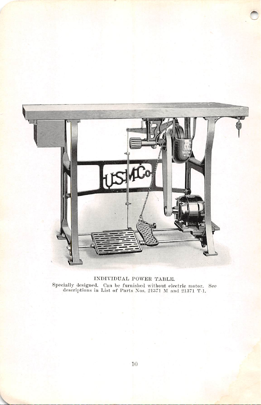
Specially
(lesigned.
(lescriptiojiH
INDIVIDUAL
Can
in
Li.st
be
furnislied
of
P;irts
rOWER
.Vos.
]0
TABLE.
witlioiit
I'lHTl
ele<'tric
ami
motor.
21371
T-1.
See
Page 12
INSTALLING
Ready
sent a popular
machines
Accurate
and
destination
sample
Caution
threads.
provided
use
new
m
to
Operate
"
run
is
Adjustment
'
carefully
inspected.
in
stitching
taken
It
will
it
is
turned
the
thread
thread
in
Any
the
style
also
perfect
left
advantageously
sewing
used.
nished.
not
nine
Pulley
ley
3f
diameters
«
tion
Style
Number
11500
11500
11500
11500
11700
machine,
the
They
can
satisfactory.
inches
"
on
inches
on a preceding
A
P
G
H
To
line
will
be
Diameters
transmitter 7 inches;
and
large
of
6,
8,
» The
C
following
style
when
ascertain
when
the
shaft
pulley,
installation
of
indicated.
working
in
the
from
the
do
no
harm
in
the
machine.
machine
New
table
be
used
If a new
found
are:
cone
9,
10,
11,
table
used
page:
Revolutions
Per
3000
3000
the
speed
speed
driven
P^eding
machine
fjfore
thoroughly
Packed
plan
in
by
trim.
machine.
threading
shipping
to
turn
indicated
by
tying
table
tops
No.
to
advantage
table
has
to
best
suited
diameters
Machine
driven
5|
inches.
12,
for
Minute
3000
3000
2800
of
13,
14
gives
the
operation
which
the
line
pulley
11
pulley
the
illustrations
to
be
each
class.
shipmetit,
run
in,
skilled
This
of
box.
the
pulley a few
direction.
the
of
ordinary
21371 B can
when
be
erected, a height
for
operators
orthc
pulley
on
Line
shaft
or
15
inches.
speed
specified
Style
Number
11700
F
11700
G
11700
L
11700
M
will
be
secured
shaft
pulley,
on
transmitter,
show
followed.
The
each
accurately
hands,
is
evidenced
the
Do
not
the
They
direction
machine
they
machine
withdraw
revolutions,
The
operator
ends
and
drawing
construction
be
promptly
the
old
table
of
of
aver.age
3i
transmitter
recommended
various
inches;
pulleys
driving
small
are
in
the
on
the
the
diameters
driving
adjusted
arrive
for
lifvolutions
Per
general
repre
the
is
at
by
the
when
the
can
the
can
be
fur
tops
are
twenty-
size.
pulleys
pul
cone
made
in
each
descrip
Minute
2500
2500
2800
3000
sewing
of
pulley
Page 13

on
transmitter,
make
an
allowance
the
product
diameter
efficiency
the
transmitter
pulley.
450
revolutions
the
driving
efficiency
on
transmitter
pulley
of
of
the
by
Example:
is
94%
"D"
and
sewing
of
the
speed
transmitter
the
product
pulley,
If
per
minute,
pulley
is
the
is
3f
3^
inches,
"C"
diameter
inches,
INSTALLING
6%
for
of
driving
of
the
and
the
speed
its
on
and
then
machine
the
inevitable
the
line
pulley
diameter
the
diameter
of
diameter
the
transmitter
of
the
the
diameter
the
speed
pulley
shaft
pulley,
and
of
the
of
the
line
is
12
driven
of
are
known,
belt
slippage;
its
diameter,
the
per
cent
driven
the
shaft
inches,
is 7 inches,
cone
of
the
the
cone
sewing
pulley
the
diameter
pulley
sewing
sewing
and
also
divide
the
of
belt
used
on
machine
"A"
the
belt
"B"
used
machine
machine
is
of
is
450 X 12" X 7" X 94%
-or
2915
R.P.M.
3f' X 3i"
The
order
diameter
factor
pulley
two
given
accordingly.
the
line
is
on
different
diameter
cone
to
Fcistening
chine
near
department
shaft
the
speed
the
transmitter
speeds
of
The
formulae
use
to
secure
Machine
the
right-hand
pulley
of
the
is
can
be
line
shaft
the
and
endeavors
with
each
customer's
designed
secured
pulley
furnished
desired
to
machine, A possible
line
with a fast
on
the
by
will
speed.
Transmitter
end
of
the
section.
12
send
the
most
shaft.
sewing
arranging
be
to
As
and a slow
machine
helpful
Table
The
suitable
missing
the
driven
with
the flat
in
deciding
Locate
the
front
cone,
belt
ma
edge
a
Page 14
of
the
base
should
the
table.
machine
in
position.
Mark
base
Do
If a table
its
normal
furnished
and
table.
The
table
the
lifter
is
fastened
pulley
alignment
Invert
the
machine.
with
front
from
Remove
bolt
from
over
to
hold
The
ing
the
swing
shaft
the
front
justment.
Place
bind,
of flat
transmitter
ample
the
belt
in
the
conforms
Turn
Should
by
turning
tion
mitter
position
are
Suitable
transmitter
that
it
lever
with
must
with
the
the
groove
right-hand
tlie
front
the
transmitter
the
the
bolt
it
temporarily.
transmitter
tension
the
frame ^ inch
by
loosening
one.
the
allowing
belt
required
pulley.
tension
around
malleable
to
the
the
pulleys
it
fail
the
with
both
should
be
set
the
table
and
bore
^-inch
not
put
block
is
fiirnished
on
the
of
sufficient
holes
should
will
clear
the
be
the
chain,
in
one
line
line
knee
bolt
with
transmitter
See
that
in
the
hole
in
edge
of
the
top
of
the
and
tighten
is
equipped
on
the flat
tlie
Fasten
pulley
for
the
on
susceptibility
to
Cut
without
the
line
shaft
iron
belt
curvatue
by
hand
to
ride
the
transmitter
the
line
be
permanently
INSTALLING
back
two
inches
under
the
holes.
on
nuts.
to
raise
table,
follow
length
will
be
be
to
found
so
located
pass
operator's
lifter
and
and
three
the
machine
shaft.
and
place
the
groove
machine
the
table.
and
table.
the
in
pulley
transmitter
Mark
bore a ^-inch
Place
nut
securely.
with a pivoted
belt.
To
secure
out
of
the
rear
belt
adjusting
lock
nuts
the
line
shaft.
of
movement.
go
around
the
belt
readjusting
and
lacing
of
the
to
crowns
as
shaft
the
the
abut
No.
cone
and
note
evenly,
required.
and
the
secured
13
from
four
countersunk
Place
the
the
machine
the
same
througli
in
the
block.
on
the
clothing,
knee
press
wood
screws.
pulley,
it
on
top
its
driving
and
that
plate
the
table
hole.
tlie
front
the
benefit
vertical
and
screw,
securely
Tighten
line
shaft,
inches
short.
transmitter
the
ends
21350.
the
teeth
whether
the
error
Once
sewing
to
the
the
front
holes
machine
higher
plan.
the
machine,
under
avoid
contact
mechanism.
The
and
the
of
tlie
table
pulley
the
center
is
twelve
under
Insert
right-hand
This
will
frame
of
for
this
toward
and
to
maintain
sufficiently
Measure
pulley
This
frame.
on
the
cone.
See
that
are
well
the
belt
may
set
in
proper
machine,
table
edge
of
in
the
and
bolts
than
The
bolts
block
side
of
the
with
It
driving
shaft
in
behind
is
in
line
of
the
inches
this
hole.
the
J-inch
hole
be
ample
regulat
feature
the
line
tightening
the
ad
to
the
length
and
the
will
give
Place
Drive
the
lacing
clinched.
runs
true.
be
rectified
rela
the
trans
by
placing
Page 15

INSTALLING
sci'ews
to
belt.
through
is
right.
runs,
holes
By
resting
The
by
to
inch.
positions.
the
of
mitter
ends
in
them
its
be
The
which
The
The
treadle,
treadle
hang
tomary
inch
ciiair
Floor
the
treadle
illustration
in
the
remaining
the
shaft.
Locate
The
the
the
former
hole
furnislied.
If
the
line
cross
the
is
to
use a pointed
placing
angles
cutting
tlie
Kemove
machine
roiuid
on
the
slant
They
bell:
it
at
two
of
slioiild
the
to
i'e<iuire(l
driving
witii
belt
Fasten
front
The
center
tlie
of
the
is
desirable.
transmitter
is
directly
approximately
latter
distance
the
machine
treadle
pitman
in a vei'lical
lumber,
leg
rest
rod
and
may
will
suit
to
increase
and
extensions.
Treadle
rear
of
the
fastened
Two
kinds
of
holes.
holes
for
the
is
easily
in
the
machine
Bore a Linch
sliaft
rotates
round
belt. A convenient
rod.
in
the
gi-oove
tal)le
top,
an
wliicli
they
pieces
the
of
rod.
be
machine,
the
table,
to
pulley.
hook
No.
dress
guard
should
heavy
The
bored ^ inch
bore
using
go
Cut
21351.
transmitter
treadle
under
one
inch
back
may
be
is
used
should
should
the
be
set
lie
attached
be
ad,justed
operator's
position.
the
height
the
lieiglit
Lifter
machine,
to
the floor.
of
floor
Style
connected
treadles
11700
("—Ready
Tighten
lifter
accomplished
hole.
reversely
the
of
the
accurate
diameter
the
lever
base
and
Slant
to
same
machine
location
be
bored
paper
line
chain,
by
the
the
the
direction
plan
diameter
pulley
can
or
card
of
the
forward
the
holes,
and
all
four
bolts.
around
the
to
belt
the
the
under
machine
inches
side
pulleys. A space
should
varied
and
With
presser
be
so
located
the
needles.
from
the
front
according
the
coiiveuienee
witli
the
enclosed
to
the
in
length
so
convenience;
some
stjdes
of
the
treadles
of
the
operator's
furnished
toot,
are
14
by
means
made
to
it
operate
Its
right-hand
that
it
consists
for
shaft
pulley
also
for
the
marking
wood
auger
the
block,
slightly
the
for
locating
as
the
round
with
the
is a simple
also
be
determined
board
holes
from
to
should
their
permanently
Measure
pulley
short.
of
the
of
one
on
front
edge
to
the
end
the
and
Fasten
table
inch
the floor
edge
of
the
operation
of
the
opei'ator.
to
tlie
side
the
incline
need
not
necessarily
of
machines
it
with a piece
chair
with
for
raising
of a lever
of a chain,
this
purpose.
shows
the
securely
round
table
if
one
to
the
machine
the
belt
belt.
point
mattei'.
conform
l)e
(Jiic
normal
fasten
length
trans
tlie
directly
between
that
should
taiile.
for
right.
of
the
of
tlie
is
cus
of
two-
tubular
the
on
with
a
The
kind
Page 16
INSTALLING
generally
taken
treadle.
kiiul
should
the
with
Knpp
As
showji
the
the
connecting
tachment.
over a point
middle
hack
niitter
be
in
ment
between
tional.
geously
under
through
Adjust
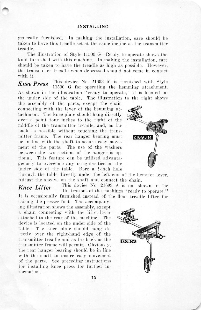
Knee
It
is
raising
ing
a
chain
attached
device
table.
rectly
transmitter
transmitter
the
with
of
the
for
formation.
funiisiied.
to
iiave
The
illustration
furnished
be
taken
transmitter
it.
Prp<t^
in
undei'
assembly
side
The
of
the
as
possible
with
frame.
line
with
of
the
tlie
two
Tiiis
to
overcome
side
of
the
table
the
sheave
Lifter
occasionally
the
presser
illustration
connecting
to
the
is
located
The
knee
fiver
the
treadle
tVame
rear
hanger
the
shaft
parts.
installing
In
this
treadle
of
Style
with
this
machine.
to
have
the
treadle
11500 G for
tlie
of
of
the
knee
four
transmitter
The
the
parts.
feature
the
when
device
illustration
the
table.
the
parts,
lever
plate
inches
without
rear
hanger
shaft
The
sections
can
any
table.
directly
on
the
This
device
illustrations
furnished
foot.
The
shows
the
assembly,
with
roar
of
the
on
the
under
i)late
should
right-hand
and
as
will
j^ermit.
bearing
to
See
knee
should
insure
preceding
pres,s
making
set
of
should
to
treadle,
touching
the
at
the
same
11500
treadle
No.
except
G—Ready
In
as
depressed
21693 M is
operating
"ready
The
illustration
the
the
hemming
hang
the
right
and,
the
installation,
making
high
siiould
the
to
operate,"
directly
of
as
trans-
bearing
to
secure
use
of
the
be
irregularities
Bore a 1-ineh
under
shaft
instead
the
machine.
edge
far
easy
ea.sy
move-
of
the
washers
hanger
utilized
the
and
No.
of
the
accompany
lifter-lever
side
hang
back
Obviously,
be
is
advanta-
on
left
connect
21693 A is
machines
of
the
except
The
of
the
di-
of
the
as
the
in
line
movement
instructions
for
further
in-
15
care
incline
chain
as
the
to
operate
the
installation,
as
possible.
not
come
fiirnisited
hemming
it
to
the
at-
the
far
must
op-
the
hole
end
of
the
the
chain.
not
"ready
door
treadle
wr.-fefcT-l
should
transmitter
shows
However,
in
contact
with
Style
attachment.
is
located
right
shows
«
I
I
MmI
WK
hemmer
shown
lever.
in
to
operate."
lifter
^
A
r
f]|r
^
be
the
care
on
the
for
Page 17
INSTALLING
Tnhlif
1
directly
fl
at
top
Thrpnti
of
pulley.
extensions
to
fiw'n/*£>
aoie
israce
behind
head
will
be
the
table
Styles
increase
screws.
drawn
^fnnH
11500 A and
and
the
the
The
downward.
its
and five
couplings
lieight
^
middle
column
center
inches
11500 F are
Nos.
of
the
furnished
of
the
should
is
to
the
thread
with
transmitter
should
eighteen
21113 A and
be
be
right
of
wires.
so
equipped
Styles
turned
located
inches
the
11700
treadle.
from
groove
21113 B respectively,
so
that
on
the
the
in
with
C,
11700
Use
the
table
front
the
thread
F,
located
1^
inch
table
that
edge
machine
wire
16
Page 18
oPEBATma
SimDlicitu
proficiency
the
work.
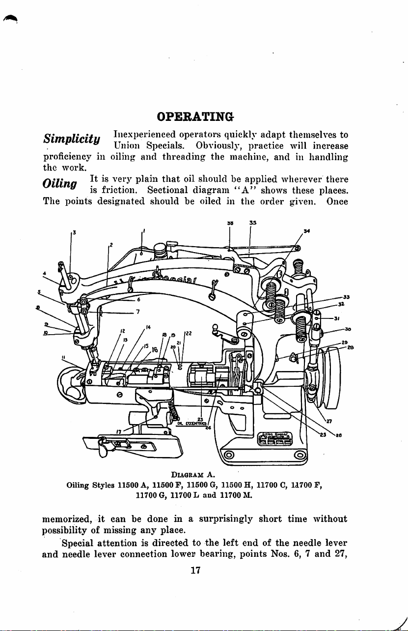
Oilina
^ is
The
points
I"experienced
^ Union
iii
oiling
friction.
designated
Specials.
and
plain
Sectional
should
operators
threading
that
oil
be
quickly
Obviously,
the
should
diagram
oiled
practice
machine,
be
applied
"A"
in
the
adapt
tliemselves
will
and
in
handling
wherever
shows
order
these
given.
to
increase
there
places.
Once
Oiling
Styles
memorized,
possibility
Special
and
needle
it
of
attention
lever
11500
A,
11700
can
be
missing
any
is
connection
Diaobam
11500
F,
G,
11700 L and
done
in a surprisingly
place.
directed
lower
a.
11500
G,
to
the
bearing,
17
11500
11700
left
points
H,
11700
M.
end
C,
short
of
the
Nos.
11700
P,
time
without
needle
6, 7 and
lever
27,
Page 19

OPERATING
which
oil-can
are
valves.
spout.
Frequent
It
is
recommended
four
times a day.
The
power
hollow
up
cup
oftener
di>nninn
it
wear
main
about
once a week.
.should
be
than
" carefully
necessary
in
the
They
are
oiling
shaft
screwed
once a month.
to
bearings.
is
necessary,
that
the
transmitter
from a compression
If
up
immediately.
tbne
an
wiped.
keep
the
maciiine
oiled
by
as
machine
is
lubricated
the
bearings
pressing
lint
be
cup,
the
quickly
given a thorough
with
solid
which
run
hot,
Refilling
operator
Accumulations
oils a machine,
as
clean
of
as
possible,
valves
absorbs
oil
should
the
will
not
lint
and
with
the
the
oil.
oiling
through
be
screwed
compression
be
required
it
should
dirt
to
a
be
make
prevent
mm
Twice a week,
machine
for
and
given a thorough
removing
looper
Threading
the
lint
grooves.
Styles
the
and
Diaouam
11500
throat
cleaning, A pin
dirt
B.
A,
11500 F and
plate
should
from
the
.18
or
oil
11500
G.
be
removed
needle
holes,
can
feed
and
be
dog
the
used
slots
Page 20

Setting
point
out
to
the
they
the
tighten
furnished
the
about ^ inch
just
above
eye.
will
go,
needles
the
for
Needles
the
Place
with
will
be
set
screw
that
The
groove
above
eye,
and a long
the
needles
the
long
in
line
with
with
purpose.
OPERATING
needles
the
eye,
as
grooves
the
the
screw
have
two
extending
or
terminating
groove
far
in
up
front,
extending
into
direction
driver,
or
grooves: A short
from
the
shank
in a spot
from
the
needle
so
that
the
of
the
stitcliing.
the
wrench,
the
bar
eyes
No.
to
a
milled
shank
as
of
Then
116.
Threading
Threading
eyelet
Each
is
it
adjacent
venience.
thread
drawn
be
against
turned
The
Styles
11700
A
thread
the
parts
to
the
looper
threads
must
the
completely
should
be
passed
tension
around
Diagram
C,
tweezer
difficult
thread
through
post,
11700
No.
of
not
but
the
.10
C.
F,
11700 G and
118 B is
access.
take-up
be
allowed
the
under
post.
11700
furnished
The
front
can
be
raised
to
cro.ss
tension
no
discs
circumstances
L
to
end
for
each
so
thread
of
the
con
other.
that
it
should
Page 21
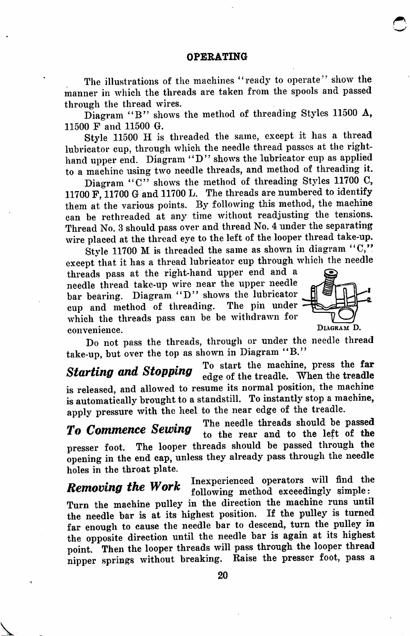
The
illustrations
manner
through
11500 F and
lubricator
hand
to a machine
11700
them
can
Thread
wire
except
threads
needle
bar
cup
which
convenience.
take-up,
ci.t
Starting
in
which
the
thread
Diagram
Style
"B"
11500
11500 H is
cup,
upper
end.
using
Diagram
F,
at
be
placed
Style
bearing.
and
Do
"C"
11700 G and
the
various
rethreaded
No. 3 should
at
the
11700 M is
that
it
has a thread
pass
at
thread
the
take-up
Diagram
method
threads
not
pass
but
over
JO*
and
of
the
the
threads
wires.
shows
G.
threaded
through
which
Diagram
two
needle
shows
11700
points.
at
any
pass
over
thread
eye
threaded
the
right-hand
wire
"D"
of
threading.
pass
can
the
threads,
the
top
Stopping
•
OPERATING
machines
are
the
method
the
"D"
threads,
the
method
L.
The
By
time
and
to
the
lubricator
near
shows
be be
through
as
shown
To
"readj^
taken
from
of
threading
the
same,
needle
shows
thread
the
and
of
threading
threads
following
without
thread
the
No. 4 under
left
of
same
as
cup
upper
end
the
upper
the
lubricator
The
pin
withdrawn
or
in
Diagram
start
the
to
operate"
the
spools
and
Styles
except
lubricator
method
it
has a thread
passes
at
cup
of
threading
Styles
are
numbered
this
method,
readjusting
the
looper
shown
through
and
needle
under
for
under
the
the
the
thread
in
diagram
which
a
Diagram
the
needle
"B."
machine,
treadle.
press
When
show
the
passed
11500
A,
the
right-
as
applied
it.
11700
C,
to
identify
machine
tensions.
separating
take-up.
''C,"
the
needle
D.
thread
the
the
far
treadle
is
released,
is
automatically
apply
_ _
To
Commence
presser
opening
holes
o
Removing
Turn
the
needle
far
enough
the
opposite
point.
nipper
and
allowed
brought
pressure
foot.
in
in
the
* *1,
the
with
The
the
end
throat
tne
machine
bar
is
to
cause
direction
Then
the
looper
springs
without
to
resume
to a standstill.
the
heel
ft
•
to
the
The
its
normal
To
near
edge
needle
threads
position,
instantly
of
Sewing
looper
cap,
plate.
U/ h Inexperienced
rVOrK
pulley
at
threads
unless
its
the
until
they
in
the
highest
needle
the
threads
will
breaking.
should
already
direction
position.
bar
to
needle
pass
Raise
20
be
pass
operators
method
the
If
descend,
bar
through
the
exceedingly
the
is
presser
the
machine
stop a machine,
the
treadle.
should
passed
through
machine
pulley
turn
again
the
be
through
the
will find
simple:
runs
is
the
pulley
at
its
looper
foot,
passed
needle
until
turned
highest
thread
pass
^j^g
the
the
in
a
Page 22

pair
of
scissors
Cut
them
by
passing
threads,
The
needle
work
short
jerk
bar
to
distance,
and
under
as
close
it
to
the
whichever
method
the
break
up
to
to
its
rear
break
the
it
to
the
rear
is
the
follow
highest
and
to
the
needle
looper
OPERATING
and
carry
fabric
and
as
to
the
more
convenient.
after a few
position,
the
left,
threads
threads
the
needle
convenient.
left.
Cut
days
raise
the
allow
the
by
giving
close
to
the
threads
Remove
or
break
operation
presser
presser
is
foot,
foot
the
work a quick
fabric.
to
the
to
the
the
looper
run
pass
to
fall
rear.
work
the
the
a
21
y
Page 23

General
convenient
use
two
than
Plan
for
needles
the
styles
The
check
the
adjuster
and
two
in
Class
ADJUSTING
steps
necessary
its
adjustment
to
follow.
loopers,
11500,
whicli
they
to
readjust a maehine
are
given
in
the
As
the
stjdes
in
are
slightly
use
only
more
one
needle
or
order
most
Class
11700
complicated
and
one
2
looper.
the
the
employed
but
front
result
For
stjdes
in
styles
In
one
While
in
are
describing
point
of
the
many
will
be
Formation
show
the
three
this
reason,
Class
11700.
Class
11500
identical.
the
of
view
macliine.
variations
secured
of
the
"Double
steps
in
r/quRC
the
It
as
positions
used.
can
by
following
the
formation
3
instructions
is a simple
the
stitches
or
movements
It
is
tliat
be
made
them.
Locked
of
22
given
matter
made
of
the
from
Stitch"
the
"Double
F'tquR^
apply
to
and
of
the
operator
these
ing
Locked
3
directly
apply
them
mechanism
parts,
there
sitting
rules,
the
accompany
illustrations
Stitch."
best
to
to
is
in
Page 24

A
careful
considerable
ences
In
with
back
and
Each
it
ascends,
as
shown
the
feed
the
front
right,
looper,
right—into
in
Figure
leaves
again
the
fabric
The
of
the
study
assistance
to
the
illustrations
the
formation
the
front
needle,
needle.
its
looper
The
is
needle
carries
throws
in
Figure
dog
moves
across
forming a triangular
the
looper
which
2.
The
the
stitch
on
ascending,
by
the
tension
stitches.
applied
ADJUSTING
of
tliem
and
in
making
are
of
the
and
formation
the
same.
its
thread
out a loop
1.
While
the
fabric
the
path
of
thread
the
looper,
recedes
action
needle
the
needle,
of
to
on
continuing
from
the
the
the
explanatory
an
adjustment.
made
in
this
chapter.
stitches,
the
of
at
the
the
the
back
looper
the
.stitch
down
the
rear,
needle
to
the
needle
front
made
through
which
is
above
rear,
and
space—bounded
the
left
and
the
needle
descends
as
the
looper
needle
with
to
shown
stitch,
as
it
thread
its
return
in
Figure
Avhich
forms
controls
matter
looper
co-operates
the
the
the
returns
by
the
thread,
toAvard
the
will
Frequent
co-operates
with
by
each
needle
fabric
the
looper
thread
3.
is
next
and,
looper
enters
throat
rocks
toward
back
of
on
as
shown
the
right,
The
needle,
tightened
stitch.
the
tightness
be
refer
plate,
of
tJie
as
to
the
the
the
in
Caution
bearing
structed,
any
consistent
thread
a
the
.straight
possible.
best
whether
rethread,
the
set
in
(1)
especially'
lint
which
(2)
See
tensions
slight
tension,
machine.
(3)
Examine
with
(4)
Remove
possible
the
(5)
Remove
as
(6)
Clean
loopers
of
needles.
mind
Note
with
points
shown
and
^
apparently
carefully
may
that
the
test
the
machine
in
the
following
at
the
have
the
needle
the
strength
are
quite
barely
is
take-up.
enough
the
needles
long
grooves
the
needles
to
roll
roll
true.
all
the
in
the
machine
fails
good
whether
tensions
accumulated.
loose.
and
them
threads
threading
thoroughly,
Oil
the
to
repair,
suggestions:
the
and
thread
of
the
thread.
The
to
steady
and
in
front,
note
on a perfectly
from
diagram.
machine
23
work
satisfactorily,
delay
machine
nipper
tensions
looper
note
and
whether
the
particularly
will
is
threaded
springs,
are
See
that
threads
them
in
passing
whether
inserted
they
flat
surface
machine,
thoroughly.
be
avoided
and
as
tight
the
require
through
they
are
as
far
are
bent.
and
and
carefully
the
grooves
Try a new
though
by
as
in
remove
as
is
looper
only
set
up
as
The
note
in
Page 25

(7)
The
and
needle
which
can
be
(8)
injured.
the
under
(9)
instructed
(10)
made
be
sure
interfere
If
checked
In
thread
Avill
cause
remedied
Unravel
The
surface
See
in
the
Before
in
the
Avorking
that
Avith
the
foregoing
Avith
Adjusting
throat
plate
take-up
breaking
by
smoothing
the
stitching
teeth
of
of
the
that
the
chapter
operating
parts,
it
runs
freely
the
frame
suggestions
the
folloAving
Machines,
ADJUSTING
needle
may
of
lioles,
have
both
the
the
surfaces
and
the
feed
dog
fabric.
pulley
is
as.sembled
on
"Repairing,"
by
poAver,
ahvays
and
that
or
Avith
each
fail,
instructions:
NOTE:
Always
Use A New
thread
become
needle
Avith
note
if
the
may
be
subject
after
turn
the
the
other.
the
eyelets,
roughened
and
cutting
on
tension
or
looper
emery
threads
threads.
cloth.
are
the
the
main
"Assembling."
any
change
machine
Avorking
adjustment
Set
by
parts
should
Of
discs
grooved,
It
cut
or
stitch
has
on
shaft
as
been
hand,
to
do
not
be
Needles
Needle
of
is
the
machine
used
Rear
on
each
The first
in
the
under
position
the
It
the
correctly
needles.
As
time
NeedUs
rect
vertical
by
dog
rear
needles
loAvest
can
guard
is
needles.
in
set
correctly
The
second
Avhen
The
it
moves
the
length
and
First
Adjustment:
Avhen
faces
turning
and
the
guard
Second
and
position
be
Avith
it
the
needle
Avill
Adjustment:
Guard
in
passing
machine,
style
side
secured
the
desired
Avhen
style
its
screAv
the
of
the
Loopers
corresponds
of
the
needle
be
points
should
through
tAVo
is
stationary,
of
the
throat
by
slightly
direction
its
is
fastened
A'crtical
hole
is
feed
dog,
stitch
"i™''
The
needle
bar
front
guard,
.secured.
of
the
be \ incli.
should
styles
they
the
fabric.
are
furnished.
and
is
fastened
plate. A slight
loosening
Avhile
the
A'ertical
faces
elongated
is
oblique
Avith
rear
in
The
loopers
faces
barely
to
the
feed
barely
to
permit
the
guard
altered.
«d.iustments
the
guard.
its
liearings.
an
unobstructed
space
24
must
proper
position
oblique
The
betAveen
Avhen
the
This
distance
'T
glance
While
the
scrcAv
scrcAV
dog.
touch
of
be
are
necessary
time.
of
the
position
adjustment
By
removing
vicAv
the
needles
toward
in a seat
A'ariation
touch
It
the
this
re-adjusted
the
only
one
milled
in
and
forcing
is
retightened.
the
rear
is
likeAvise
rear
of
adjustment.
to
needles
center
controls
of
of
the
are
is
the
is
the
needle
of
at
the
rear
style
its
of
set
the
each
bring
cor
tAVO
made
feed
the
their
size
Page 26

and
form
of
the
an
accurate
gauge
lowest
even
with
connecting
loosen
tightening
see
that
the
right-hand
ley
in
farthest
ball
joint
securely.
has
not
With
from
the
should
adjustment
No.
21225-^,
position,
the
rod,
nuts,
use
the
the
left
the
direction
position
in a vertical
Again
been
the
point
be
approximately
needle
loops. A very
will
having a "V"
the
point
of
right-hand
which
wrencli
looper
ball
nut
is
provided
No.
connecting
joint
has
slightlj%
the
machine
to
the
left,
position
apply
the
altered.
foregoing
of
adjustment
the
front
the
ADJUSTING
be
found
from
dicated
In
using
"V"
Avith
right.
the
back
edge
of
115
and
side
then
loosen
gauge
looper
same.
convenient
by
slot,
the
the
edge
by
the
this
slot
enclo.sing
the
wider
Then,
looper
the
gauge
with
right
turn
rod
nuts,
play
in
all
the
left
nut
runs
till
the
right-hand
and
tighten
to
make
of
the
to
the
manner
using a looper
center
gauge,
the
them
sure
back
center
of
which
of
the
wider
dotted
side
should
care
positions.
securely;
the
line
hold
the
of
the
needle
be
by
turning
and
left
toward
should
loopers
nut,
the
right-hand
that
the
being
made
threads.
the
First
turn
hold
looper,
of
the
back
gauge
are
the
front
of
securing
adjusting
is ^ inch
side,
as
in-
in
the
cut.
it
with
the
needle
to
the
at
its
to
come
the
looper
To
rear.
In
be
taken
to
tighten
the
pul
at
their
the
left
nut
adjustment
distance
needle
Third
Adjustment:
with
respect
the
machine
right
to
the
upper
below
to
have
with
the
1
and 2 respectively
made
by
turning
adjustment
the fingers
and
press
With
the
turn
the
upward
opposite
to
runs
left,
is
edge
the
under
the
upper
functions
moving
the
needle
of
of
the
the
right
pulley
if
the
direction
the
even
of
side
edge ^ inch
the
bar
the
left
thumb firmly
hand,
so
needle
till
the
of
needles.
if
To
set
loopers,
the
with
turn
point
the
needle
of
the
looper.
the
loopers
of
the
needle
in
its
bearings,
An
hand
back
loosen
that
the
bar
is
to
the
needle
the
needles
the
machine
of
the
left
side
eye
should
below
and
stitch
formation.
bar.
Care
excellent
of
the
against
the
two
needle
bar
be
lowered;
bar
25
front
of
the
be
Enough
the
looper,
needles,
should
as
that
will
plan
presser
the
front
needle
connection
is
to
be
at
their
proper
pulley
in
the
looper,
front
moving
needle.
direction
approximately
variation
without
as
The
destroy
is
guide
of
bar
turn
raised.
is
shown
adjustment
be
taken
as
follows:
bar
the
set
screws,
Avill
the
pulley
allowable
interfering
in
Figures
to
the
oblique
bearings,
needle
be
height
from
Then,
iiich
is
avoid
Place
bar.
and
moved
in
the
Page 27

ADJUSTING
Fourth
enter
the
needle
pass
back
the
left
of
in
making
loosen
the
to
slightly
point
possible
spot
position
in
that
the
Whenever
its
position
through
passes
to
Looper
main
It
purpose
needle
Fig. 2 of
tlie
then
the
looper
the
required
altered,
in
tlie
to
on
the
of
proper
position
permit
relation
the
oblique
looper
n
d e Front
should
the
tlie
this
Thread
shaft
consists
is
points
eyes
of
release
Adjustment:
loops,
of
the
needles. A small
the
needles
this
adjustment.
two
screws
rock
shaft.
position.
by
required
alter
the
looper
the
point
adjustment
has
become
either
needle
looper
Avith
respect
j.
Guard
it
glance
fabric.
Avithout
adjustment.
they
as a background,
which
This
loosening
direction,
position
shank,
has
to
with
the
bent
is
I A guard
toAvard
The
Take-up
is
located a device
of a take-up,
to
hold
the
liaA'e
passed
the
stitch
the
them.
formation,
loopers
are
When
the
should
To
change
fasten
permits
The
position
the
looper
while
of
either
but
it
is
be
altered
back';
of
of
the
or
is
designed
replaced
to
the
back
force
the
guard
striking
and
for
cast-off
looper
treads
beloAV
and
to
the
left
loopers
have ^ inch
piece
the
the
the
of
re-tightening
looper
not
advisable
more
the
needle
in
the
of
is
attached
the
front
front
is
set
it.
The
Cast-off
controlling
Avire
the
looper
continue
of
move
of
white
will
be
position
looper
looper
rocker
either
looper
set
screw
point
than ^ inch,
needles,
bar
is
for a different
machine,
the
needle.
to
needle
of
the
correctly
scrcAV
Wire
the
and
thread
taut
until
threads
to
the
middle
to
the
left
space,
paper,
of
great
of
eccentric
and
the
by filing
to
do
it
will
incorrect,
the
into
machine
Avhen
hole
looper
as
placed
assistance
the
loopers,
fork
to
be
point
may
forcing
screw.
the flat
this.
to
bring
be
evident
or,
machine.
carefully
front
its
in
passing
it
is
elongated
threads.
eyelet.
the
descending
as
shoAA'n
hold
them
of
the
needles,
to
they
to
to
moved
be
the
It
is
If
the
it
that
note
looper
proper
barely
Their
in
until
A
simple
be
made
side
of
and
Avhile
machine
of
the
take-up
points
is
looper.
should
alloAvable
test
as
folloAA\s:
the
thread
so
doing,
runs,
until
to
be
to
liaA'e
to
determine
Take
eyelet,
turn
the
the
circular
beloAv
the
the
Avhether
hold
draAV
the
machine
threads
points
move
edge.
middle
even
26
of
the
them
Stop
of
the
they
are
looper
sloAvly
pulley
from
the
at
this
looper.
A\dth
the
in
adjustment
threads
through
in
the
direction
long
straight
point.
Enough
loAA^er
edge
on
the
the
eyelet,
edge
The
needle
A'ariation
of
can
left
the
the
Page 28

The
are
set
correctly
change
ing
the
screw
arras
of
height
in
the
the
thread
when
they
of
the
cast-olf
ADJUSTING
eyelet,
just
arras,
wire
change
frame.
which
clear
the
project
the
over
main
shaft
height
the
main
sleeves.
of
the
shaft,
To
support
Intermittent
^
right-hand
clarap
Their
thread
where
holes
to
their
operation
the
leave
adjustment
PpfiH
the
right-hand
the
teeth
ing
it
rocker
rocker
of
venient
one
located
the
purpose
through
they
as
shown
tighten
movement
regular
some
Finn
^
feed
crank
two
set
The
height
project
on
the
is
necessary
No.
No.
the
feed
hole
of
the
under
Looper
end
of
the
looper
can
threads
is
to
prevent
the
tensions
pass
from
in
Fig.
on
the
threads
toward
readily
manner
slack
is
end.
screws
from ^ inch
kind
11742,
11743
dog
will
screws
and
between
made
by
locate
equidistant
link
pin
Before
whicli
of
the
of
work
to
loosen
also
to
the
can
be
found
in
the
throat
Thread
cylinder
when
the
2.
the
be
drawing
the
bending
the
No.
making
feed
being
the
the
feed
be
altered
the
plate.
is a pair
the
the
instead
looper
They
as
soon
left
and
observed
tensions
the
feed
from
the
305 A is
any
fasten
dog
to
inch
sewed.
two
two
screws
rock
in
the
left
feed
Nipper
of
loopers
take-up
eyes
are
the
its
is
screws
shaft
by
rear
from
of
holding
to
set
correctly
as
the
returned
by
threading
threads,
and
the
outer
spring.
bar
so
ends
of
eccentric,
change,
left
end
correct
above
the
Before
which
which
No.
moving
of
the
rocker.
Springs
nipper
are
the
loopers
about
the
the
it
is
to
when
fasten
297.
the
cylinder
springs,
moving
drawing
taut
throat
when
have
the
care
being
nipper
springs.
feed
throat
and
slotted
necessary
the
feed
the
throat
plate,
making
fasten
the
Then
feed
The
other
c 0 t il
which
to
the
right.
additional
the
threads
plate
needle
tliey
begin
completed
inch.
Their
machine
taken
in
to
The
dog
travels
plate
slots,
at
its
to
loosen
bar.
tips
of
the
depend
any
change,
the
left
feed
right
feed
the
height
bar. A con
for
access
screw
to
is
0
ReguMting
There
left
and
the
to
turn
the
three
of
them.
turning
three.
the
left
it
in
left
Length
screws
The
the
Turning
shortens
the
direction
hand
and
of
in a row
length
stitch
regulating
it
to
the
it.
the
hold
the
Stitch
will
be
found
of
stitch
right
To
loosen
machine
machine
is
altered
screw
lengthens
nut,
runs.
pulley
27
elTZ'tllhlft
with a lock
by
loosening
which
use
the
stitch,
wrencli
Apply
with
the
is
the
and
No.
the
wrench
riglit
nut
to
the
the
nut
largest
of
turning
115
and
with
hand.
Page 29

ADanSTING
Alwaj's
Note
the
turned
the
slots
tlie
machine
When
guard
altered.
Needle
which
needle
stroke,
up
into
the
elasticity
needle
It
and
the
edge
of
Tensions
the
looper
them
a
glaze
is
always
_ .
I
ension
rators
highest
arm
and
for
this
binding
arm
do
tighten
eifect
too
far
in
the
will
tiie
must
be
Thread
the
needle
threads
and
aid
the
needle
loops
is
set
correctly
top
of
the
holes
as
threads
in
pa.ssing
, For
or
or
soft finish
preferable
Kelease
entirely
position.
the
purpose.
the
end
not
come
„
"ressure
machine
enable
while
Needle
iveeaie
an
near
the
machine
the
needles
Thread
inreaa^^onirouer
eyelet
for
the
lock
nnt
of
turning
to
the
throat
feed
the
needle
readjusted
the
right,
the
plate.
work
rear
guard
each
towards
Take'Up
threads
as
the
the
needle
of
the
when
crossing
the
in
tension
is
consistent
should
through
regular
three
-
release
The
lever
Care
of
in
To
regulate
fabric, a thumb
the
center.
are
Controller
the
needle
must
needles
thread
holes
in
the
threads
when
wire
the
sizes
thread
in
This
neejjie
the
adjustment
connection.
should
the
contact
and
heavy
the
is
approximately
needle
on
the
with
be
quite
the
machine.
stitching,
larger
can
the
loopers.
is
only
threads.
tensions
be
lever,
and
with
the
pressure
screw
Only
to
feed
properly,
being
withdrawn.
tlireads
after
any
stitch
If
pass.
are
needle
bar
be
taken
at
regulating
feed
dog
it
is
turned
the
is
fastened
time
the
styles,
Ijearing
Its
purpose
nearly
controller
throat
needle
plate.
facilitates
seams.
bar
fV
thread
their
loose;
the
than
used
applied
is
Their screw
that
the
sufficient
will
its
eyelet.
threads
strength.
only
needle
the
in
When
when
the
made
by
to
avoid
the
tension
of
the
will
be
and
to firmly
"P'""
be
found a lever.
right-hand
change
has
been
screw.
will
strike
too
operator.
to
length
near
is
located
at
the
in
drawing
It
the
is
at
inch
should
sufficient
threads
looper
the
needles, a soft finish
to
the
set
presser
moving
holes
the
points
stud.
presser
found
pressure
P"""*
the
far
to
the
feed
of
the
stitch
the
upper
a
wire,
is
to
contact
bottom
each
also
eounteracts
formation
its
lowest
above
the
be
The
tension
to
should
threads.
tensions
correctly,
foot
the
separator
are
elongated
lever
connection
of
the
separator
foot
upon
on
top
is
required
hold
the
It
end
which
made.
If
it
is
ends
of
the
left,
dog,
the
is
needle
over
the
of
their
stitch
of
the
position
upper
as
tight
on
steady
be
two
While
for
the
the
sepa
is
at
its
the
of
the
to
fabric
carries
co-oper-
28
Page 30

ates
with
two
moving
the
right
and
the
other
Its
purpo.se
loops
and
the
right
of
the
the
needles
shown
a
in
The
few
stitches.
Fig. 2 of
adjustment
descending
thread
the
needles
ley
the
lowest
above
needle
harm.
used
more
high,
the
the
loopers,
the
aid
the
at
washer
adjusts
foot
it,
creased
amount
ine
tensions
throat
If
any
descend,
by
hand.
To
ascertain
pulley
position,
the
needle
A
slight
and
The
as
the
than
has
become
The
position
presser
friction
and
reverse. A supporting
in
holding
lever
and
its
highest
to
As
it
is
its
ascends
the
eyelet
amount
on
It
is
inadvisable
connecting
is
to
under
latter
will
and
assist
the
The
needles
and
plate
when
needle
thread
it
may
the
till
the
needles
place
clamp
variation
the
slack
thread
guide
for
gV
inch,
it
bent,
of
bar.
Moving
between
increases
the
rack
rack
position.
make
this
connected
position
or
for
descends,
moves
of
the
thinner
the
ADJUSTING
eyelets
to
the
cause
sides
sufficient
of
the
carry
the
descending
stitch
formation.
can
only
position
do
not
draw
there
is
no
the
needles
is
be
readily
amount
pass
the fingers
collar,
between
in
the
thread
having
the
making
will
be
evident
or
is
designed
the
eyelet
the
rack
the
needle
the
slack.
collar
in
position
should
adjustment.
in
slack
to
two
mesh
Sufficient
with
the
any
thickness
as
thicker
the
opposite
on
fabric.
set
it
eyelets
fastened
left.
friction
loopers
the
loops
needle
be
made
after
of
the
needle
slack
in
are
at
drawn
through
observed
of
slack
down
through
on
the
and
draw
the
slack
in
smaller
the
adjustment.
that
for a different
is
altered
upward
loops
Moving
is
placed
when
freely
room
presser
bar,
or
or
direction
the
thicker
lower
than ^ inch
on
the
29
to
the
needle
between
that
the
movement
to
the
right
points
the
machine
eyelet
in
is
thread
the
needle
their
lowest
the
while
the
needle
correct
through
tensions,
turning
the
fabric
threads a short
upward.
in
the
thread
the
back
needle
amount
and
when
will
fabric.
thinner
of
If
one
of
by
moving
lowers
the
the
rack
on
the
once
the
be
found
the
eyelet
fabric
and
fabric
needle
slack
the
the
machine.
the
under
downward
set.
presser
When
takes
and
below a straight
lever,
lever,
of
to
threads
one
to
the
needle
to
the
the
path
of
function
has
when
the
as
made
the
needle
below
position.
as
the
the
pul
threads,
to
turn
their
distance
in
the
front
will
do
no
should
variation
loopers
the
eyelet,
side
be
is
too
rack
on
reduces
of
the
is
acts
presser
The
in
bar
teeth
foot
the
lever
to
of
is
automatically
the
presser
passes
under
up a de
an
increased
when
the
Page 31

ADJUSTING
needles
on
be
n
CyUnder
threads
They
in
the
direction.
looper
looper
slack
Lap
represents
In
designated
Duck
greatest
to softer
operation,
of
loosen
the
ment. A screw
the
as
the
fabric.
of
foot
the
the
are
at
their
the
thickest
seriously
f
are
each
eyelet
A
should
Seam
^
interfered
j
rrij^ j n i j.
Thread
when
the
set
correctly
thread.
nearest
The
connecting
slight
threads
variation
be
Feller
the
smallest
determining
fabric,
and
heavy
thickness
materials
and
for
the
greatest
To
alter
the
delivering
entering
the
screws
folder
The
the
margin
can
be
margin.
presser
thickness.
the
two
screws
end.
end
are
bodily
lateral
turned
Care
foot.
highest
part
of
position
the
work,
with.
Eyelets
loopers
If
the
right-hand
rod
will
used
the
denim
of
like
width
driver
to
to
position
on
slightly
should
are
when
the
threads
loopers;
eyelet
will
permit.
between
do
no
as
the
f®""!
attachments
internal
required
the
stiffness
require a much
the
garment.
shirtings,
this
reason
of
the
near
the
Tighten
should
prevent
the
tightened.
secure
the
the
of
the
upper
on
be
and
the
presser
as
its
control
Their
position
at
their
farthest
there
is
the
are
too
if
too
slack,
is
swung
the
slack
harm.
guide
The
for
marked
designate
measurement
capacity
of
the
making
of a feller
position
smallest
taut,
swing
as
far
in
the
thread
within
their
at
fabric
larger
This,
however,
which
yield
readily
require a capacity
folders
middle
both
be
upper
It
desired
presser
surface
the
taken
with
iand
the
screws
inserted
half
will
then
margin
foot
of
the
presser
to
avoid
bar
the
move
to
in
being
be
on
lip
fabric.
to
increase
either
foot
is
of
the
threads
within
swing
the
the
has
necessary
the
the
to
the
noticeable
to
the
it
in
the
opposite
to
the
left
front
and
having
the
capacity,
for
capacity
slightly
pivot
the
retain
the
forced
the
adjustment.
eirele
delivering
use
to
considered.
than
does
not
to
the
in
adjustment,
upper
the
lower
dowinvard
to
each
side
controls
the
cylinder
The
or
decrease
needle
striking
bearing
will
looper
right.
slack
right
as
the
back
least
on
the
which
end.
with
a
the
apply
folding
excess
half
of
adjust
half
of
move
of
the
width
presser
30
Page 32

BEPAIBING
Lapping
thoroughly
Powdered
cannot
of
the
The
parts
with
Plus
are
made
See
list
clamp
to
use
them
clamped
internal
standard
Caution
frame
loosen
Bearings
with
be
thoroughly
metal
bearings
are
left a trifle
their
associated
Sizes
. looper
in
of
parts.
.
LI
ob e Bearings
screw,
to
they
bearings
the
standard
in
position.
diameter,
size,
removing a bearing.
with a .screw
the
screw
gasoline
emery
will
continue
of
main
plus
sizes
r>
•
can
with
they
.257
inch.
should
and
only
ess.
and
run
or
crocus
washed
the
small
parts.
rock
be
an
internal
"Without
driver
push
out,
indefinitely
needle
to
allow
shaft,
shaft,
for
use
These
301^^
easily
internal
will
be
be
taken
or
or
tap
powdered
VVhen
them
should
and
lever
for
needle
presser
where
arc
provided
retained
replaced
diameter
diameter
specific
furnhshed
to
avoid
Do
not
similar
it
out
oil
nnished,
in
oil.
never
what
is
the
grinding
connection
their
lever
stud,
bar
bearings
in
position
when
of
of
.257
instructions
to fit
breaking
pry
tool. A better
from
stone
cleanse
be
used
retained
and
being
lapped
feed
and
presser
have
for
the
worn.
.254
inch
inch
regarding
the
the
open
the
the
under
for
this
the
because
in
the
pores
i)rocess.
all
similar
together
rock
shaft,
guide
been
worn.
needle
by
means
It
is
advisable
and
after
they
needle
bar
frame
slit
in
idan
side.
proe-
parts
they
bar
bar.
of
a
ream
are.
their
of
when
tlie
is
to
Tension
and
Tension
rules.
it
Avill
Eccentric
be
had
off
the
Nuts
slightly
spread
Post
unscreAving
present
an
Forks
through a hole
Reversible
eccentrics.
hardened
position,
Ferrules
unused
®
the
slotted
the
post,
surface
provided.
drilled
steel
turn
are
in
becomes
it
on
the
end.
provided
the
ferrule
to
the
thread.
te
for
Access
the
shoes
31
to
front
are
too
loose
post
as
the
with
hardened
may
be
wear,
of
provided
damp
the
right-hand
tlie
cylinder.
to
maintain
far
as
possible,
i.eedie
steel
turned
screws
fork
to
take
the
its
threads
fer
so
that
are
may
wear
Page 33

REPAIRING
o,
Sharpening
re-sharpened
teeth, a small
A
ASSemOling
of
looper
is
placed
Long
The
right.
set
of
machine
enter
force
move
end
sloAvly
tightened
its
own
the
drawing
should
should
will
at
its
eccentric
rock
it
to
.
hi'
the.se
parts
eccentric
so
straight
nipper
The
machine
screws,
tlie
play.
The
parts
Tlie
inches.
The
be
shaft.
the
one
shaft.
runs,
the
groove
it
as
far
the
pulley
needle
of
its
so
weight.
do
the
be
bent
tube
be
turned
needle
left
between
lowest
fork
right,
j
Feed
and
re-hardened.
triangular
relation,
should
are
that
the
edge;
spring
of
Turning
the
in
to
against
bar
own
that
the
If,
not
fall,
needle
can
of
the
so
Tliis
mea.surement
lever
position.
acts
To
maintain
and
the
r\
Dogs
maintain
placed
edges
(2)
eccentric
pulley
which
screw
the
the
is fitted
weiglit.
after
obviously,
lever
be
readily
needle
that
ball
the
as a collar
feed
When
piece
of
the
the
main
not
be
with
will
circular
is
is
secured
enters
the
machine
in
the first
shaft.
right
as
the
right-hand
correctly
The
left
end
connecting
link
seen.
lever
the
should
butfer
Tighten
and
the
lateral
eccentric
the
teeth
For
removing
oil-stone
take-up
shaft
is
changed.
the
number
rotate
in
edge;
placed
the
the
of
tin;
the
distance
is
the
for
with
to
the
groove
pulley
hole
To
properly
shaft
side
in
needle
the
lever
the
lever
direction
connection
between
vital.
be
turned
upper
clamp
the
right-hand
position
fork
of a feed
sharp
will
be
found
and
eccentrics
spotted,
The
to
the
(3)
and
feed
the
left;
following
short
straight
the fibre
shaft
with
at
the
right-hand
in
the
coming
head
of
its
bearings
lever
lever
is
bearing
nut
to
the
into
set
the
will
the
frame
stud
nut
also
falls
with
the
not
in
line.
in
which
assembly,
centers
so
that a small space
when
securely.
end
of
the
feed
left.
dog
have
annealed,
edges
of
the
convenient.
in
proper
the
position
eccentric
the
order:
and
take-up
(1)
edge.
side
to
the
two
pointed
end
direction
view
main
permit,
to
when
should
slowly
needle
No.
is
the
of
bar,
must
shaft,
then
prevent
it
falls
By
with
the
lever
1216
exactly
buffer
Tlie
feed
the
feed
move
the
be
of
bar,
C,
is
32
Page 34

NEEDLES
Type
denotes
details.
sured
eye,
Number
needle.
covered
Number
Type
Application
herewitli.
of
numerically,
style
Style
11500
11500
11500
11500
11700
11700
11700
11700
11700
Number
in
and
The
No.
121
124
128
130
921
929
the
of
Machine
No.
A
F
G
H
C
P
G
L
M
Descriptions
the
kind
of
The
latter
thousandths
is
stamped
and
Size
Number
Type
Numbers
by
this
catalog
is
the
definition
Definition.
Eound
point,
round
Bound
point,
round
Bound
point,
ball
eye.
Bound
point,
ball
eye,
Spear
jioint,
round
Spear
point,
ball
eye.
of
Type
Set
opposite
needles
macliine
which
as
the
makes
point,
denotes
round
round
goveriiment.
round
wide
shank,
the
of
an
inch,
in
the
needle
represent
of
the
needles
are
listed
of
the
shank,
short,
shank,
short,
shank,
short,
shank,
short,
shank,
short,
shank,
short,
Numbers
each
Style
can
be
used.
variety
it
impractical
and
Size
length,
largest
diameter
midway
shank.
the
used
below.
needle.
double
double
double
double
double
double
ered
Number
Type
of
the
to
needle
groove,
groove,
groove.
has a Type
Number.
groove, finish
of
the
between
the
Collectively,
complete
in
Set
groove,
groove,
groove,
by
Numbers
materials
definition
the
styles
opposite
nickel
plated.
nickel
plated,
nickel
nickel
nickel
this
is
machines
catalog
the
Type
sewed
plated,
are
The
and
blade,
shank
the
of
machines
each
spotted
plated,
plated,
are
arranged
show a preference.
Type
Number
Needles
121
124
128, 130,
121,
128,
128,
128,
128,
121,
Number
former
other
mea
and
Type
of
the
Type
spotted,
spotted,
spotted,
cov_-
listed
Number
on
each
of
Used
929
921
130,
929
130,
929
130,
929
130,
929
921
33
Page 35

]\I
//I
£€
requesting
opposite
Size
1920;
FNp
use
use
Special
to
our
ing
to
utmost
assured.
Cnf 1 n ^ coraprelieiisive
€
Catalog
each
Numbers
also
other
GpnuitiP
uenuine
of
genuine
Machine
interest
the
very
the
most
approved
precision.
O
Oy
No.
other
Type
and
descriptions,
valuable
NppdlP<i
lyeeaies
Union
to
best
Special
Company,
maintain
needles
scientific
The
NEEDLES
Special
45.
Listed
Numbers,
information.
therein
which
^"ccess
Needles,
or
its
the
reputation
obtainable.
principles
maximum
catalog
machines
new
Avere
in
the
as
subsidiaries.
of
They
efficiency
of
needles
may
be
will
be
found
Size
Numbers,
solely
operation
secured
furnished
Obviously,
the
macliines
are
designed
and
are
made
and
for
obtained
used
of
these
only
by
the
by
according
durability
all
by
arranged
the
old
prior
to
ma-
by
the
Union
it
furnish
with
the
are
is
Genuine
"trade
^
. .j
Size
Numbers
ligible
order
100
needles
'UNTON
•
To
^
empty
should
would
Needles,
are
put
up
in
SPECIAL'
have
mark."
orders
promptly
package, a sample
be
read
Type
given.
as
128;
See
follows:
Size
.054.
packages
All
other
and
needle,
marks
on
marked
needles
accurately filled,
packages.
or
the
at
tiie
are
bogus.
Type
An
intel
top
the
and
34
Page 36

ORDERING
REPAIR
PARTS
Plates
List
be
found.
ordering.
shown
of
Parts
It
Always
When a part
no
specific
For
and
similar
use
convenience
articles
(—) A dash
indicates
that
machinist's
indicates
the
worn
difficulty
u.se
for
(□)
the
(I)
(*)
part
out
of
these
repairs
the
A
part
supply
A
that
A
star
can
part.
of
protecting
only.
Identifying
of
the
smaller
di.stinguish
All
catalog
o
!•
part
in
them
which
in
groups.
definition
check
is
not
necessa,ry
is
is
mentioned
are
in
absence
square
is
commercial
house,
double
the
component
in
the
only
be
We
particular
Parts
parts
from
numbers
they
Belting,
powdered
parts
from
the
used
in
in
ordering,
repeated
the
"plate
of
an
in
the
dagger
"symbol
furnished
are
forced
our
customers
parts,
IS
are
stamped
parts
represent
appear,
belt
hooks,
oil
stone
similar
the
of
to
all
in
illustration,
"symbol
and
in
parts
stamped
similar
plates
each
part
symbol
furnish
machines
the
definition.
minor
after
number"
to
can
be
the
"symbol
cannot
to
order
upon
tlie
to
adopt
and
Avhich
with
with
in
the
same
belt
fasteners,
Avill
be
against
eacli
order
are
in
appearance
to
the
and
the
covered
parts
column
readily
be
by"
return
this
ourselves
furnished
its
an
appearanee.
part
promptly
list
its
principal
its
definition
plate
number.
by
sucli
as
major
part,
of
the
by"
column
purchased
to
order
furnished
column
of
rule
because
against
part
number.
identification
regardle.ss
screw
furnished,
and
size
of
parts,
uses
this
catalog,
screws
list
of
indicates
by"
.separately.
indicates
the
broken
improper
at
list
ead,
letter
drivers
are
the
will
before
nuts
parts
in
any
column
that
or
of
the
prices
par
Some
to
of
the
and
Tfirmti
at
the
are
insured
the
po,stage
notice.
buyer's
unless
and
.strictly
Express
risk
f,
otherwise
insurance.
o,
net
and
b,
shipping
cash
freight
directed,
35
and
point.
A
.subject
shipments
Parcel
charge
to
change
are
post
is
made
without
forwarded
shipments
to
cover
Page 37

r::JJJ-i I IJJ
1 I
tTti
fT.
|II705K|
ITITT
IjJvJJJ-
|n77>5"Hl
mm-
|ll705
TnnTi
nTTJui
B|t./
1
i
Page 38

[uszTT
1117^46
Specify
: , .
ITT,
Specify
Tinnmaiwn
Gauge
Gauge
H524
MT724C
J
Specify
Specify
Gauge
Gauge
Page 39

Plate
0
-^
No.
3—i
■m|
ull
Si2e
II
527
0-
^
Specify
Width
Hem
Specify
^Kffl720
Gauge
ril720M_^^V^
Specify
Gauge
F^H
Specify
Gauge
Page 40

1708
II708
A
Specify
Gauge
l«
[213501
Page 41

I
Page 42

Plate
22569
2 2
73
5
No.
6—^Full
Size.
22 7 5
mB
@aa
ra
aa
m
22565
EKiaigi
^9
eseem
89
igEs
EEKl
rrwf-i
22560^^H22565
ffl
aB
iD
fefcf*i>
Baa
UB
KUCT/M
em
tsiBM
22586
2253
9
Page 43

BL
1!^
5'430
3.5
B
C|
I 3 7
5 2 -
A
Page 44

.2S38
ri286
16
n
Page 45

11755
54^»iT30^
-
V
Page 46

il
tsi
136^^
Page 47

i
1004
Page 48

Page 49

Pirate
No.
13—One-half
Size
Specify
Specify
and
Capacity
Gauge
Gauge
o
0--
and
o
Specify
a
Capacity
Specify
11
Specify
I
Capacity
Gauge
Gauge
and
and
Capacity
Capacity
--wp
Specify
gq.
Capacity
Page 50

1/722
B
174.4.
I
757
(1723
/nfl.5
Page 51

'111
Hi
212061
212.01,
Page 52

Oo
[II70I
B|
21130
2
ZM02.
I30A-4
A-2
D
ZI250H
2U39A2
Page 53

LIST
OF
PARTS
Symbol ' not
to
order
by
16
17
IS
20
25
C
25
CC
33
34
t
SOL
t
30
R
37
L
37
R
C41
42
A
47
4S
*
50
C-6
50
D
52
A
54
50
56
B-2
50
56
CA
50
CB
58
t * See
Page
The fiKurcs
to
^e
notice
Feed
Screw,
'•
Looper
Looper
"
"
"
"
"
Guiding
Hand
Xeedle
"
Xeedle
" Bar,
*'
" Lever
" Lever
" Lever
" Clamp
" Clamp
" Clamp
" Set
" Clamp
" Clamp
Intermittent
H.5.
in
She
be
used
in
orderitia.
on
page
2.
Crank
Ferrule
" Stud
" Stud
" Stud
for
cloth
inch
long,
also
for
Rocker
Stud,
Connecting
" "
" "
"
"
u
Stud,
for
Lifter
Screw
Lever
Stud
" "
Bar,
hardened
for
Xo.
hardened
for
styles
Bar
Set
Screws
Thread
Thread
Link,
Xut,
Collar,
Collar,
Screws
Collar
11700
Collar
11700
11700
Nipper
last
column
These
Refer
to
Nut;
also
Washer
plate
attachments
for
right-hand
X'o.
23291
hardened
" Xut;
21693
Rod
Bail
Ball
Ball
"
Ball
"
X'ut,
u
Xut,
left
hemmer
Pin.
hardened
Xut,
Washer
and
32
gauge
and
in
Clas.s
Xo.
Eyelet,
Ej'elet
hardened
hardened
for
for
X'o.
88
Pin,
C
Pin.
C,
11700 L and
F,
11700G,
Spring,
" Screw
refer
only
to
tlic
parts
an-
insert
for
for
Xo.
furnished
30
pink
hemmer
F.
all
gauges
also
for
R
Joint
Assembly,
Joint
Assembly,
Joint
Screws.
Joint.
Stud
left
thread
right
thread
scroll
hardened
ground,
styles
in
Class
ground,
standard
11500
8S
A.
left,
for
Screw
X'o.
Xo. 4 gauge
X'os.
4-2'
and 5 gauge
B.
jj
inch
long,
"
inch
long,
Xo. 5 gauge
11700
L
rear,
for
Xo.
52
plates
illiiatratitiii
at
prices.
list
R
scroll
and
Xos.
Xo.
Xut
X'o.
on
Style
standard
11700
styles
in
98
A.
styles
in
for
for
looper
threads
90.
the
parts,
prices
for
repairs
on
Style
G,
11500
21093
all
capacities
21093
left
right
97
A.
IS.
11500
G
diameter
diameter
Cla.ss
Class
styles
.257
.257
11500
11700.
in
Class
No. 4 gauge
Xos.
4^
gauge
Styles
11700
and
arc
only,
G;
K,
inch,
inch,
11700
Style
Styles
C,
Page 54

LIST
OF
PARTS
to
94
95
96
97
97
°j>ee
Symbol
order
60
60
60
60
60
60
64
64
69
69
72
73
73
75
78
SI
82
86
87
87
88
88
88
90
91
93
93
Page
A
A-322
A-325
A-328
A-331
A-334
A
B
S
FD
A
A
U
A
B
A
A
The figures
not
See
to
notice
by
Presser
" "
" "
" "
" "
" "
Presser
"
Thread
Set
Screw,
" "
" " fillister
Screw,
" for
Set
Screw, fillister
" ''
Locating
Screw,
Stud,
Screw,
Set
Screw,
Spot
Screw,
21614
Clamp
Screw,
Set
Screw,
11614,21102
Screw,
35.
in
be
used
in
on
page
Bar,
hardened
standard
standard
standard
standard
standard
Spring
"
Stand
square
f
21130
21693
for
for
looper
cast-olT
No.
headless,
Screw,
for
regulating
for
hand
for
throat
for
needle
headless,
2538,
for
headless,
gauge
Screw,
for
for
intermittent
B
Screw,
inch
^
inch
all
capacities
4
inch
No.
headless;
21113,
for
for
cylinder
11758,
for
looper
the
last
column
Refer
refer
These
to
pink
ordering.
2.
and
diameter
diameter
diameter
diameter
diameter
Regulating
Screw
" "
Pin, 4 inches
head,
cup
inch
long,
for
A-4;
also
K,
21693
looper
eccentric
head,
for
needle
guards
wire
bracket
head,
for
11753
convex
headless,
cone
length
lifter;
also
for
plates;
also
thread
take-up;
for
feed
11753, 12865,
needle
bars;
also
concave
styles
take-up;
in
also
nipper
for
presser
feet
long,
for
thread
long,
for
feed
long,
for
202
for
21113
feed
D,
take-up
A
right-hand
A,
21140
eccentric
21173
end
cap
14625
connecting
53
only
to
tlie
parts
are
furnished
insert
for
ground,
standard
plus
plus
.000
plus
.009
plus
.012
plus
.015
Lock
long
point,
thread
for
Nos.
Q,
21693
fork
back
looper
upper
needle
end,
for
lower
end,
for
of
stitch
Nos.
11663
for
Nos.
also
crank
link
21113
for
Nos.
end,
for
Class
11700
for
Nos.
springs;
lubricator
dogs;
also
thread
feed
fork;
also
support;
rod
ball
plates
illustrating
at
prices.
list
diameter
.003
inch
inch
inch
inch
inch
Nut
inch
diameter,
stand
seats
21685,
R
of
styles
lever
needle
attachment
11741
11525,
11725
for
Nos.
pin;
also
B,
21140
142
0,
needles
in
164-1,
367,
also
cup;
for
Nos.
eyelet
rocker;
also
for
Nos.
also
for
Nos.
joints
the
prices
Nos.
21693
in
Class
link
lever
support
11534,
for
A
23364
Nos.
8318-32
for
Nos.
also
for
416
spring;
for
301
A,
11558,
parts,
for
repair?
.319
18
21130
F,
21693
pin:
link
23364
Nos.
G
2,
4w
21642
No.
A,
23256
Nos.
322,
11725
and
are
only.
inch.
thread,
A-2,
H.
11700.
also
for
pin.
. . .
yokes.
C. . .
100
B.
and
E,
21645.
B,
also
for
100
B,
11306,
A,
.
10
0
7
16
.
5
Page 55

LIST
OF
PARTS
Symbol
to
9S
9SA
100
104
100
107
lOS
JO!)
110-1
110-2
110-3
110-4
115
no
IIS-B
137
133
t
130
141
142
154
lo()
153
153
•
160
•
160
•
IGOA-ii
order
B
A
A
C
B
A-2
A-l
by
Screw
Thread
Looper
Tension
Wrench, ^ inch,
Thread
Needle
Needle
Needle
Tlic fintires
not
to
1)0
used
notice
on
for
11533,
" for
Sttuid
•'
"
"
"
"
"
Thretid
"
Post,
" Spring
'•
Nut
'■
Disc,
" Spring.
" Spring,
" Spring,
" Spring.
" 'i2
Tweezers
Thread
"
"
"
"
Lever
"
"
"
"
"
Bar,
"
"
in
tlie
last
noliiinn
in
ordoriiiK.
paRc
2,
Kefer
fen.«ioii
'■
'• '•
"
''
11733.
needle
lever
Wire.
'•
■■
■
"
thrctid
16
Serew.
."^crew.
Extension
Extension
Corpting
Take-up
"
'■
rear,
1^
Ferrule
liardened
.026
incli
.023
inch
.040
11500
inch
F
.013
Styles
11500
hardened,
liardened,
Controller
"
"
"
" "
" Bail,
" Ball
" Bull
" Thread
" Ttirend
" Thread
" hardened
" hardtmed
"
"
"
Buffer,
hardened
Chuii|)
Clamp
hardened
for
No. 2 gauge
for
No. 4 gauge
for
No.
refer
only
Tfiosc
imrt
to
pink
insert
eyelets;
11739
B,
tliretid
eyelets
inehes
11500
H;
32
24
22313.
Eyelet
ICyclet
inche.s
long,
and
lapped
diameter
diameter
diameter
ineli
diameter
A,
11500 G and
for
for
Thread
Tliread
Lever
Lever
Puck
Pack
wood
fibre
Boll.
Nut
ICyelel,
rigiit
Eyelet,
left,
Eyelet
Screw
and
ground,
and
ground,
and
ground,
I-J-
gaug<?
to
the
luro
furnished
for
prices.
iilso
11742
long,
for
also
for
threads
threads
Serew.
.Screw,
Screws.
Spring
Spring
for
wire,
wire,
wire,
loojier
connecting
needle
Eyelet
Eyelet
.'Vssembly
Screw
Serew
No.
1279.
No,
1230.
for
No.
standard
styles
standard
style.s
standard
styles
jdates
illustrating
at
list
for
Nos.
Styles
styles
to
inch,
to
inch.
32
threads
24
threads
No.
83.
Serew
No.
looper
thread
for
looper
for
thread
for
needle
wire,
for
styles
elamp
nut
Screw
No.
88
styles
in
98
A.
in
Class
in
Class
in
Class
the
prices
291,
11500
in
Class
No.
95.
No.
22S13.
to
94.
threads
lubricator.
thread
needle
in
Class
rod
A.
Class
diameter
11700
diameter
11700
diameter
11700
parts,
for
repairs
424,
A,
11500
11700,
inch,
to
inch.
tliread
11700.
nuts
11700
.257
.257
.257
and
1005,
No.
in
Style
are
only,
G,
...
95.
No.
. . .
in
. .
inch,
inch,
inch,
15
8
12
12
12
7
6
9
6
7
10
10
10
t * See
Page
35.
54
Page 56

LIST
OF
PARTS
to
•
160
162
108
168
202
202
202
288
200
201
294
297
297-40S
297-110
297-113
297-410
299
300
301
303
304
305
310
310-408
316-410
310413
310416
Symbol
order
104-1
A-5
B
A
B
A
A
The figures
not
by
See
Needle
" "
"
Needle
'•
I'n-fwer
''
Needle
"
"
"
"
Attacliiiient
Looper
-Adjusting
Feed
" "
" "
" " "
" "
Feed
" Bar
" Eccentric,
" Eccentric
Adjusting
Main
"
Feed
^ "
f>ooper
"
"
"
"
to
be
used
notice
on
Bar.
" Connection
Clatnp
Set
Spring,
"
'•
Thread
'•
Pock
Screw,
Pock
Bar
Pin,
Pin,
11500
Screw,
Shaft
" "
Crank
Pock
" "
"
" "
"
in
the
last
column
in
ordering.
page
hardcnod
Set
Screws
" Take-up
These
2.
Kefer
to
niid
for
No. 5 gmiKo
Screws
Collar,
for
" Screw
No.
88
.085
inch
.065
inch
Pin
No.
1361
Take-np
Take-iip
.Assembly,
for
No. 2 gauge
Post
Post
" Take-up
" Take-up
Support,
Sliaft
Shaft,
"
'■
"
right, 1 g
left,
G,
Cap,
Link
"
Shaft,
Dro])
Collar
" Screws
for
feed
7y
inches
diameter
stundurd
standard
standard
standard
1^-
ground,
11500
Spot
Scri^w
for
feed
for
stitch
Screws
Pin,
eecentric.
"
g,.t,
hardened
inch
standard
"
standard
Screw
inche.s
inches
originally
11;
standard
"
standard
refer
only
to
the
(oris
are
insert
for
furnished
pink
Kroinid,
styles
No.
88
A.
No. 2 j^auge
No.
SO.
B.
nietal,
for
styles
nietal,
for
styles
A.
for
Style
Screw
No.
87
Plate
Shaft,
ttiui
" Thumbscrew
No.
eccentriir
long,
.407
and
hardened
incli
diameter
diameter
diameter
dianieler
long,
long,
marked
also
for
style.s
No.
96.
crank
link
regulating
No.
22563.
Screws
and
diameter
diameter
diameter
diameter
Note:
pin
No.
ground,
eccentric
plates
illustrating
at
prices.
list
standard
in
Class
styles
in
in
Class
in
Class
styles
11700
No.
94.
U.
inches
ground
98.
feed
cam
and
plus
.001
plus
.003
plus
.006
plus
.009
Iiardened
hardened
"A,"
in
Class
screw
This
No.
305
88.
standard
plus
.001
plus
.003
plus
.006
plus
.009
the
prices
for
diameter
11700
Class
11700
11500
11700
in
Class
M
long,
fork
ground,
inch
inch
inch
inch
and
ground
and
ground
for
Styles
11700
replaces
diameter
inch
inch
inch
inch
parts,
and
rejairs
.257
ineli,
11500;
hardened
standard
11500
the
are
only.
jil.sc
A,
non-
.407
10
8
10
7
7
10
5
0
G
10
10
10
11
14
♦
Sue
Page
35.
00
Page 57

LIST
OF
PARTS
Symbol
to
order
31S
319
322
325
330
333
33^1
330
337
351
352
353
354
356
357
358
359
364
367
413
413
414
414
414
414
414
416
416
416
420
421
Tlic fimires
not
by
See
SiTow,
11729
Lnnper
"
L'loper
" Eccentric
Frame
A
Mkmi
" " "
Tension
" Thread
" Thread
" Tlireiid
" Threail
Cylinder
A
Cylinder
A
Intermittent
A
A
B
C
D
A
B
A
Oil
" "
Table
" "
" "
" "
Lifter
" "
" "
" "
in
the
last
to
be
lined
notiee
on
for
loiipcr
A
Connecling
Eccitnlric.
11501) A 1
Loopnr
Shaft
Post,
Class
eolumn
in
orileriiig.
page
2.
Refer
rock
Ilod,
"
" Ntit,
" "
ground,
l.inO
Spot
Threa<l
Sleeve,
|-|
Pin
front.
2=^
11700
These
to
pink
shaft
Screw
Guide
inch
No.
incites
Eyelet. « inch
I'lyelct, 3 inches
styles
ill
Clas.s
Eyelet, l inches
styles
in
Class
Eyelet
End
Cap
Screw
" " " Support
" " "
" "
" " "
Cover
"
"
"
"
"
Can,
with
Support
"
Spritig
Spring
" "
Hinge
Spring
" Spring
" Latch
" Latch
Nipper
"
''
" "
spout
Screw
Screw
Pin
Spring,
"
"
Spout
Brace
Assembly.
Flange,
right
Flange,
left
thread
" Column
Lever
Column
Assembly
Extension
Extension
Nut.
Screw.s
Casting
" Stud
" Chain.
40
in^s
refer
only
to
the
parts
insert
plates
are
furnished
for
prices.
right-hand
length
over
all 9 inches
left
thread,
Nut.
right
thread,
originally
G.
11500
H;
also
No.
96.
long
1362.
long,
for
long,
for
long,
11700
long,
11500.
No.
OS.
Screws
No.
97.
Screw
No.
22564.
Pin
Washer, ^ inch
front,
for
.Screw
Eccentric
Eccentric
looper
No.
Spot
thread
right
thread
No.
93
A.
long
illustrating
at
list
jiriees
bearing;
No.
37
No.
37
marked
"U"
for
styles
looper
thread
needle
thread
for
two
looper
for
one
hole
threads
90.
Screw
the
parts,
for
repairs
also
L.
R.
for
in
Class
in
threads
looper
No.
89.
and
are
only.
for
No.
Styles
11700.
styles
in
in
thread
in
0
10
11
9
0
II
11
11
12
12
12
12
12
0
7
3
11
9
16
16
15
15
15
5
15
56
Page 58

LIST
OP
PARTS
Symbol
to
order
4-2-2
42:^
424
42(i
420
A
4
S3
000^.
()0045-^
wx-u-6
000-o-H-
005
005
A
°
65040
^
650-24
^
05048
1000
1002
1003
1004
1005
1007
lOOS
1216
C
The figures
not
to
be
Sec
notice
Lifter
Treadle,
"
■■
Lifter
Lever
Lap
Seam
used
on
" Rest
"
Di.se
by
Tension
" "
" "
" "
" " " ^ inch
4
" " "
" "
" "
" "
Stove
Bolt,
" "
" " flat
Thread
Lubricator
"
"
"
"
"
"
"
"
"
"
"
"
Needle
Lever
in
the
last
column
in
ordering.
2.
Refer
for
Styles
styles
Pin
Pin
Screw
These
to
in
imgc
Spring
" Pin
Separator
Feller,
Lever
complete,
for
No. 4 gauge
standard
"
inch
"
6^
inch
" ^ '"ch
inch
"
Screws
No.
"
Adjusting
"
Adjusting
flat
head, j inch x I;'
the
rear
hanger
flat
head, j inch x 3
table
head, J inch x 6
table
Assembly
Cup
" Cup
" Cup
" Cup
" Bracket
" Bracket
" Tension
" Tension
" Tension
" Tension
" Tension
" Tension
" Tension
Coiinecfion
Screw
Pin
Felt
refer
only
to
the
98.
are
for
A,
11700
plates
furnished
prices.
11500
parts
pink
insert
11500
Class
No.
Stud
pivot
adjustment, ^ inch
folder
is
No.
capacity,
capacity,
capacity,
capacity,
capacity,
25
for
for
for
for
for
C.
No.
No.
No. 5 gauge
No. 5 gauge
No. 5 gauge
Screw, ^ inch
Screw,
inch
inches,
on
Nos.
21093
iiiehc.s,
inches
No.
93.
Screw
No.
Plate
Post
Post
Spring
Spring
Nut
Felt,
.-\.ssenibly,
valve
centers
inches;
1230
15430 L and
98.
No.
1346.
Ferrule
No.
Ferrule
No.
108.
lower
with
oiling
must
includes
C,
1230
110-2.
illustrating
at
F,
Style
23291
4^
4^
long;
the
list
prices
for
11500
H;
11700 C fobsolete,
E)
gauge
gauge
also
for
long
for
the
lower
A,
21693
for
fastening
for
fastening
No.
1347.
No.
107.
upper
and
system;
measure
one
G,
two
distance
cjich
15430
No.
41040
lower
exactly
C,
parts,
and
arc
repairs
only.
also
for
capacity,
No.
11534.
section
of
M
machine
machine
to
to
spring
between
4f|
Nos,
1230,
15430
D,
G
15
12
10
8
4
5
13
13
13
13
13
13
6
6
°
See
Pago
35.
57
Page 59

LIST
OF
PARTS
t
t
J
Symbol
to
order
1230
1230
1230
1230
1230
1230
1275
1275
1275
1275
1275
ffee
Page
The figures
not
See
by
Xeedio
A
" Lever
" Lever
B
" Lever
" Lever
C
" Lever
" Lever
" Lever
D
G
A
E
F
H
J
36.
" Lever
" Lever
in
to
be
usoii
on
in
puize
notice
Liivcr
each
154.30
15430
oiling
replact:
valve
holes
lapping
" Lever
'■
Lever
" Lever
.006,
1275
section
" Lever
.006
represents a stud
" Lever
.003.
11-003
" Lever
.002)
(.002.
.001)
(.012.
.003)
section
.1-003-006
tion
represents a stud
.003
" Lever
" Lever
bearing
the
conqiound
the
lust
cohiinii
refer
orih'riiiK.
2.
Refer
CoiiiitH-lion
Nos.
1230
Connctdion
Coiinei'lion
Connection
Connecticn
Cenneclion
Connection
C.
Ctmnecticn
D,
Connection
Connection
system.
No.
oilers
after
compound
Connection
Stud,
standard
Stud
plus,
.012,
E-0()3
Stud,
))lus
inch;
specify
only
These
parts
to
pink
Insert
Upper
A,
1230
Upper
Upper
Bearing
Bearing
Tube,
Tube
Tube
Bearing
Lower
Note:
1.54-30
cr
Nc.
41046
the
parts
wa.«hed
Bearing
diameter
size
on
.018
inch;
represents a stud
size
on
plus
plus
Sttid.
plus
size
.00()
inch;
equal
.specify
repre.sents a stud
Stud,
plus
size
unequal
(.001.
.003)
(.003,
.002)
(.012,
.006).
and
(.001,
.001)
(.006.
.006)
Specify
lever
.006)
(.006.
.00.3)
(.018,
first
represents a stud
and
.006
inch
on
plus
inch
on
lever
section
.8(ud
Screw
Felt
ha.s
the
No.
No.
.stud
been
58
15430
lever
washed
Stud
of a needle
felt
frcm
to
the
arc
furnished
for
prices.
Bearing
B.
1230
Bearing
Bearing
Valve
\'alve
length
Nut.
Nut,,
Valve
Bearing,
When
No.
1.5430
G.
The.se
have
been
out
Screws
frame
section,
specify
lever
section,
amount,
.003
on
each
plu-s
plus
.006.1
(.003,
.003)
(.018,
plus
section
phis
lever
.006
inch
22586.
L.
and a needle
and
replace
out.
jilates
ilhistruting
at
list
Assembly;
D,
22580
Screws
Spring
Spring
Screw
overall
2g
upper,
lower,
right
for
use
ordering
M,
ultto
oilers
lapped
No.
22587.
viz.:
plus
utnount.
plus
.003
viz.:
Example:
inch
on
section,
amount.
.003
inch
on
on
each
section,
(.(K)2.
.001)
.002)
(.003,
(.012,
.001)
.00!)
ainounl.s
last.
.003
inch
section.
on
frame
Note:
Before
it
the
partfi.
iiriccs
for
repairs
includes
A
No.
22587.
No.
22586
inches
left
thread.
thread,
with
spring
No.
1230 G to
order
two
arc
(o
plug
together
and
.001, .002, .003,
Example:
inch
on
.001,
.002,
1275
lever
.section
viz.:
.001, .002.
Itxaniple:
each
section.
viz.:
(.002,
.006)
(.012,
(.018,
.002)
arranged
Examples:
on
frame
1275
.1-006-003
section
lapping
lever
stud,
after
the
aud
arc
only.
one
A.
No.
No.
valve
spring
the
the
frame
.003,
F-003
127.5
.
(.001.
.003)
(.006.
.002)
(.018,
frame
127c
sec
and
the
remove
lapping
11
Page 60

LIST
OP
PARTS
Symbol
to
order
1279
12S0
12<S(1
12N0
12JS()
134G
1347
1301
I3G2
IGSS
1504
2538
S318-32
10334
10G73
10074
11300
The figures
not
by
See
Needle
" "
A
" "
" "
" "
B
" "
" "
" "
Tension
A
A
Presser
Main
Upper
" "
Supporting
Needle
A
Feed
«
"
"
"
Feed
" " "
in
to
be
used
notice
on
page
Lever
" Ball
Post,
" Ferrule
Spring
Shalf
Sleeve
Folder
" Hinge
Collar,
"
Clamp
" Clamp
" Set
Screw.s
" Bar
" Bar
Thread
Thread
Eccentric
" Fork
" Fork
" Fork
" Fork
Lift
Cam,
the
last
in
ordering.
2.
Uefer
Ball
Clamp
Clamp
Link
ground,
12904
Link
Pin
Link
Pin
Link
Pin
Link
Link
Pin
Link
Pin
front,
Pin
Pin
Spring,
Spring
for
'■
Screw
Collar,
Collar
No.
Fork
each
14552,
Fork
originally
Spot
coiunni
refer
Tlicse
to
pink
Bolt
Nut
Pin
Assembly,
includes
C,
22500
Set
Set
Pin
Ball
Ball
Bali
for
needle
for
Style
Screw
Pin
needle
No.
for
No.
Screw
22580.
Eyelet,
Eyelet
Screw
As.seinbly;
No.
22570
Set
Screws
Adjusting
Shoe
No.
Shoe
Screw
marked
Screw
only
to
the
parts
are
furnished
insert
for
one
Screw,
upper,
Screw,
lower,
No.
12904
Spring
Spring
Screw
threads
11700
No.
225(H.
thread
88.
32
gauge
No.
89.
for
styles
No.
also
10674
No.
Screw
14552.
No.
"AZ,"
No.
96.
plates
illustratiiic
at
each
No.
No.
C.
No.
list
oiling,
Nos.
77.
78.
22560
prices.
internal
L
controller
in
styles
Class
rack
in
11700
22768.
feed
cam
and
two
each
96.
No.
294.
22570.
for
Style
the
prices
for
hardened
1280
Class
fork;
includes
Nos.
11.500
parts,
and
repairs
A,
1286
11700
90,
F
arc
only.
and
B,
.
one
294,
.
10
59
Page 61

LIST
OF
PARTS
Symbo)
to
order
by
]
1.501
11.50.5
11.505
D
11505
H
11.505
.J
11507
11.50S
11510
1151.3
11.520
11.520
A
n.520
H-g
11520
11.520
H-l
11520
H-|
11.520
H-|
11.520
H-1
11.520
H-U
11.524
11.524
H
11.524
J
11.525
The figures
not
See
Attachment
in
to
be
used
on
in
lage
notice
.Support
'■ '■
'■ '■
'■
,
"
"
"
"
"
"
Ftted
Dog,
for
" for
" for
" for
" Screw
Ix)oper,
with
" without
" Set
Screw
" Needle
" Needle
" Hocker,
Prcsser
Poof,
" hinged,
" for
" for
" for
" for
" for
" for
" for
" Spring
" Spring
" Spring
" Hinge
" Screw
Throat
Plate,
" for
"
" for
"
" Screws
"
" Needle
"
" Needle
the
lust
column
orderitii:.
2.
Itcfer
Assembly,
Yoke
Yoke
"
Yoke
Drop
" Drop
" Drop
" Drop
" Drop
" Drop
Styles
11500
henmiiiig
on
styles
Style
11.500
tiiaking
on
slyle.s
No.
needle
guard,
needle
No.
Guard,
Guard
hardened,
for
Style
cio.sod
Style
Style
styles
styles
styles
styles
style.s
wide
No.
Screw
Supporting
Pin
No.
for
Styles
Style
making
wide,
No.
styles
refer
These
to
pink
Xu.
Locating
Thumb
Plate
Plate
Plate
Plate
Plate
Plate
A,
legs
in
Class
G
hems
in
Class
9.3
A.
for
guard
22565.
marked
Screw
for
11.500
llo00G-|
11,500
in
Class
in
Class
in
Class
in
Class
in
Class
11534.
No.
No.
91.
IloOO
11.500
hems,
on
styles
S7.
Rear
in
Class
Rear
Guard
only
to
the
parts
are
furnished
insert
for
for
Style
115.37.
Screw
No.
Screw
Shaft
Shaft
.Shaft
Spring
11.500
and
arm
11500
ranging
11.500
styles
C.
for
No.
73
styles
A
front,
for
G4
11.500,
11.500,
11.500,
11.500.
11500,
605.
Screw
11534
C.
A,
11.500
G
ranging
in
Class
Guard,
11.500
Screw
plates
illiiBtrating
at
prices.
11500
Screws
No,
No.
11.5.3S.
No.
O.S.
No.
2.S.S.
Ann
No.
.\nn
Screw
No.
H
holes
from
-g
inch
in
Class
styles
in
A.
in
Class
styles
in
making
making
making
making
making
No.
87
H
from j inch
lloOO
hardened,
No.
the
list
prices
for
G
SI.
200.
117.39
No.
117.39
A.
of
athletic
to
!§
11.500
Class
11500
11500
Class
11500
hems f inch
hems f inch
hems f inch
hems 1 inch
hems
U.
marked
87.
parts.
and
repairs
B.
9.S.
underwear
inches
wide.
wide..
wide.
wade.
to
I5
"X",
are
only.
wide,
inches
inches
for
.
.
.
60
Page 62

LIST
OF
PARTS
Symljol
to
order
11526
11527
11527
11528
11534
11534
11537
11538
11550
II558
11614
11663
11701
11704
11705
11705
11705
11705
11705
The figures
not
by
See
A
Feed
Presser
D
Presser
Throat
" "
Spring,
" Screw
" Supporting
C
Hinge
Attachment
Attachment
Cylinder
Take-up
Looper
Hemmer
B
B
E
F
G
H
Attachment
Cast-off
Feed
" "
" "
Feed
" "
in
to
be
used
notice
on
[tage
Dog,
for
" Screw
Foot,
" for
Foot
Plate,
for
presser
Pin,
for
"
"
Thread
"
" "
Thread
"
"
"
"
Eccentric,
" Spot
Bell
" "
«
"
"
"
"
"
"
"
"
Wire
"
" Screw
Dog,
for
for
for
Dog,
f:r
for
the
last
column
in
ordcriiiB.
2.
Refer
Style
11500
No.
for
Style
Style
Screw
No.
for
Style
Screws
foot
No.
605.
Screw
presser
Support
u u
Support
" " "
Eyelet,
Eyele.
"
" Spring
"
ground,
11500
Crank
Lever
'•
Support
" Yoke
" Yoke
" Yoke
" Drop
" Drop
" Drop
" Drop
" Drop
" Drop
No.
No. 5 gauge
No. 4 gauge
No.
4^
No.
32
No. 5 gauge
refer
only
These
imrts
to
pink
insert
F
93
A.
11500
F
11500
H
91.
11500
F
No.
87.
No.
11520
No.
87
foot
No.
11520
Yoke,
for
assembly
Locating
" Thumb
Drop
Plate,
for
stylos
Screw
No.
for
looper
Supporting
No.
Spring
Screw
originally
F
Screw
No.
Coiled
"
Coiled
Assembly,
11700
L
No.
11730.
Locating
Thumb
Plate
Plate
Plate
Plate
Plate
Plate
22524.
Styles
Style
gauge
Styles
gauge
Style
Styles
to
the
plates
arc
furnisliod
for
prices.
H
U.
H
Screws
Screw
for
assembly
Screw
No.
in
Class
227(58.
thread
Screw
104.
No.
marked
90.
Spring,
Spring
for
Styles
Screws
Screw
No.
117.38.
Screw
No.
Shaft
No.
Shaft
Arm
Shaft
Arm
Spring
No.
11700
C,
11700
C
11700
11700
11700
illustrating
at
list
prices
No.
11501
No.
81.
No.
290.
No.
11501
98.
II500
in
styles
No.
in
97.
94.
"AM",
for
Style
No.
11500
86.
Stud
11500
No.
81.
No.
290.
98.
288.
No.
11739
Screw
No.
11739
A.
11700
L..
C.
11700
L.
C
F,
11700
G..
the
parts,
for
Class
F,
B.
98.
,
aii'J
are
repairs
only.
lloOO
for
Style
G
117C0
3
3
11
11
9
13
C.
16
61
Page 63

LIST
OF
PARTS
Syn-bol
to
order
11705
11705
11707
11708
11708
11700-2
11709-4
11709-4^
11709-5
11710
11713
11715
11720
11720
11720
11720
11720
11720
11720
11721
11722
11722
11722
11722
11722
11723
11724
11724
11724
*
See
Pflgc
oy
K
L
A
A-5
B-5
F-4
F-1^
F-5
F-32
M-2
B
B-.);3I
B-533
B-530
B-539
A-4-J
A-5
B-32
The figures
not
See
Feed
" "
" "
Looper,
in
to
be
used
notice
on
page
Dog 5 row.s
for
Screw
front,
styles
" front,
" front,
gauge
" Set
" back,
" back,
" back,
" back,
" Set
" Needle
styles
" Needle
" llocker,
Needle
Lever
" "
" "
Presser
Foot,
" "
" for
" "
" for
" "
" "
" "
Eccentric
Main
Take-up,
Throat
"
Shaft,
" "
" "
" "
" "
" Cap
" "
"
Plate,
" "
Pulley,
for
Spot
" for
the
last
column
in
ordering.
Tluise
2.
Kefer
to
of
teeth
Xo. 5 gauge
Xo.
11724
Xo. 2 gauge
Xo.
93
with
needle
ill
Class
without
needle
without
needle
styles
in
Screw
No.
225(55.
for
No. 2 gauge
for
Xo. 4 gauge
for
Xo.
4^
for
No.s. 5 and
Screw
No.
73.
Guard,
ill
Class
Guard
Screw
hardened,
Ball
Clamp
Ball
Clamp
for
No. 5 gauge
for
No. 5 gauge
No. 4 gauge
for
No.
ly
No. 5 gauge
for
No.
32
for
No. 2 gauge
Screw
No.
originally
" Screws
hardened
standard
standard
standard
standard
Cap
looper
for
for
and
ard
diameter
diameter
diameter
diameter
diameter
No.
304.
Screws
thread
Screw
No.
No.
4-i
No. 5 gauge
No.
32
refor
oiily
parts
are
pink
insert
at
rear,
styles
in
D-5
Style
A.
guard,
11700
guard
guard
Class
11700
styles
styles
gauge
styles
32
gauge
marked
"T"
11700
No.
for
styles
Bolt
No.
Nut
No.
Style
Style
Style
gauge
Styles
Styles
gauge
Style
Style
91.
marked
No.
22597.
ground,
.530
inch
phis
plus
phis
phis
No.
22563.
89.
gauge
Styles
Styles
gauge
Style
62
to
the
plates
illustrating
furnislie<l
prices.
for
setting
Class
at
11700,
for
11700
for
Nos.
or
needle
in
Class
in
Class
in
Class
styles
for
Nos.
73
A.
in
Class
1279.
1280.
11700
F
11700
G
11700
C
11700
11700
C,
11700
C
11700
M
"All"
originally
.001
inch
.003
inch
.006
inch
.009
inch
11700
11700
C,
11700
list
prices
inackinaw
using
2,
4,
4^
guard
11700
11700
11700
in
Class
2,
4,
4^
II700
C,
11700
11700
marked
C,
11700
11700
C
the
parts,
and
repairs
only
sleeves
plate
are
for
throat
and 5 gauge
pin,
for
No.
11700. . . .
and 5 gauge
L
L
"B",
stand
L
L
on
32
Page 64

LIST
OF
PARTS
Symbol
to
order
11724
11724
11724
11724
11725
11725
11729
11736
11738
11739
11739
11740
11741
H742
.;743
11744
11745
11750
11751
11753
C-o
D-5
E-2
A
A
A
B
by
The figures
not
to
be
used
See
notice
on
Throat
Plate
■'
"
"
" for
"
" for
"
" Screws
'■
"
"
" Needle
Feed
Dog
" " "
Cylinder,
Attachment
"
"
"
"
"
"
"
Cylinder
Cover
"
"
Feed
Rocker,
" Screws
"
" right
Feed
Bar
Feed
Crank
"
" "
Cylinder
Bearing,
Presser
Thread
right,
" Screws
Bar
" " "
« " "
in
the
last
in
ordering.
]>agc
2.
for
for
in
Needle
styles
Needle
Note:
at
factory
Screws
Support
" Yoke
" Yoke
" Drop
" Drop
" Drop
" Drop
" Drop
" Spring
" Spring
" Latch
" Latch
left
Screws
Link
for
Connection
column
refer
These
to
pink
ports
Refer
No. 5 gauge
setting
mackinaw
Class
11700,
No. 2 gauge
No. 4 gauge
No.
87.
Rear
in
Class
Rear
Guard
Rear
Guard,
in
Class
Rear
Guard
This
part
is
No.
318.
Yoke,
for
Locating
Thumb
Plate,
Plate
PlateSpring.
spring
Nos.
shaft
Plate
Plate
No.
356.
Screw
Screw
No.
98.
No.
95.
Adjusting
Eyelet,
looper
No.
318.
Screw
for
Screw
rock
Screws
Set
Screw
only
to
arc
insert
for
Styles
using
Style
Style
Guard,
11700
Screw
hardened,
11700
Screw
furnished
assembly
for
Screw
No.
104
or
arm
Shaft
Shaft
No.
357.
No.
SO.
No.
styles
No.
shaft
No.
No.
the
plates
illustrating
furnished
at
prices.
11700
F,
sleeves
on
feed
dog
11700
M
11700
C
hardened,
No.
marked
No.
97.
only ^ hen
No.
Screws
No.
Screw
No.
tissembly
No.
98.
Note:
11739 A to
11739,
also
.\rin,
Arm
Screw
303.
in
Class
11700
22768.
88.
77.
the
parts,
for
rciwira
G
11705
B
K
"Y"
for
are
and
only.
styles
styles
made
list
prices
11700
No. 5 gauge
No.
marked
87.
"BH'"
repairs
11701
81.
290.
No.
11701
B
Wheiiorderingcoiled
replace flat
order a drop
springs
plate
adjustable
No.
98.
'.
arc
for
13
16
12
14
14
14
14
11
14
3
63
Page 65

Symbol
to
order
LIST
The
fieurcs
in
be
used
on
page
the
in
not
See
to
notice
by
last
column
ordering.
2.
Refer
OF
refer
Theseto
pink
PARTS
only
iKirta
arc
insert
to
the
plates
furDiahcd
for
prices.
illustratiiif;
at
list
the
prices
for
parts,
repairs
and
only.
arc
IlToo
11750
11750-322
11750-325
11750-328
11750-331
11750-334
11757
1175S
12534
12805
12873
12873
12957
12904
12993
14552
14625
14070
14671
14072
15430
C
15430
D
15430
L
A
E
C
A
Hand
Lifter
" Stud
Presser
Guide
" "
" "
"
" " "
" "
Cast-off
Take-up
"
Wire
" "
Thread
"
Needle
Bar
Thread
Collar,
for
pulley
" Set
Renewable
Screws
Bearing,
"
"
Spring
Waslier,
11500
G;
also
Needle
Lever
Stop
Screw,
for
also
for
No.s.
Shoe,
for
eccentric
Screw
No.
Feed
Dog
Needle
'■ '■
Looper
Eccentric
"
"
"
*■
"
Needle
"
"
'■
" Fork
" Fork
"
" Fork
Lever
" "
" "
No.
80.
Bar,
hardened
inch
"
standard
«
standard
" standard
standard
"
standard
Bracket
Screw.s
Eyelet,
fur
" Supporting
" Spring
" Spring
Eyelet,
shaft
on
No.
88.
upper,
eter g inch,
" lower,
§
inch,
'■
Clamp
for
left
heininer
for
No.
23304
Link
Pin
Ball
knee
press
21093
K,
21093
forks
22570.
Rear
Guard,
"
Fork
Fork
Fork
Connection
"
.-Vssembly;
22592,
Set
Adju.sting
Sho(r
Shoe
Tube
Tube
Oil
and
ground,
diaineler
diameter
diameter
diameter
diameter
No.
75
looper
No.
Screw
for
styles
Screw
No.
knee
press
standard
plus
plus
plus
.009
plus
plus
A.
threads
in
Screw
No.
104.
No.
94.
in
Class
22768.
for
Style
.003
.000
.012
.015
ground, ^ inch
for
needle
ground, f inch
for
needle
Screw
H
interlocking
R
for
Style
Screw
includes
and
two
Screws
No.
Screw
Screw
Nut,
Nut,
21093
J.
Retaining
1275
E.
No.
scroll
each
No.
left
1275
22509
11500
No.
Nos.
72.
No.
22570.
right
Felt:
long,
bar
guiding
arm
97.
thread
F,
inch
inch
inch
inch
inch
styles
97.
11500
11.500
long,
bar
external
on
G
one
each
72,
14072,
22592.
thread;
also
1275
diameter
in
Class
G
exteroai
diameter
stud
on
Style
11500
Nos.
22570. . . .
also
for
for
Nos.
1275
1275
J
H,
.319
11700.
diam
Style
G;
14671,
No.
A.
10
14
11
64
Page 66

LIST
OF
PARTS
Symbol
to
order
i
15430
21102
21113
21113
21113
21130
21130
21139
21140
21140
21145
21173
21201
21202
21203
21204
21205
21206
21208
21225-i-
21290
21350
See
Page
M
D
A
by
B
A-2
A-4
A-2
A
H
The figures
not
Sm
Needle
" " "
Thread
Thread
Screw
Screw
Loopcr
Lifter
Malleable
35.
in
to M used
notice
" " "
" "
in
on
page
Lever
Stand
the
ordcriiiR.
2.
Connection
Base
"
Stand
"
" "
"
" "
" "
" "
" "
" "
" "
" "
" "
" "
« "
" "
" "
" "
" "
" "
" "
" "
" "
" "
" '•
" "
■'
"
Wire
Wire
" Wire
Wire
Wire
Wire
Wire
Seat,
Seat,
Scat
Seat
Seal
Wire
Wire
Wire
Wire,
Wire
Wooden
Rod,
Rod
Rod
Driver,
round
round
round
round
"
octagon
Driver
" Set,
Adjusting
Lever
Treadle,
Iron
last
eolumii
refer
only
These
Refer
parts
to
pink
insert
BeariiiR,
bly
No.
Bearing
Screws,
32
Screws,
24
Wire
Assembly,
11500
H;
also
one
each
Nos.
No.
88
Set
Screw,
Set
Screw,
Extension, 6 inches
Extension
Extension
No.
22S13.
Coupling
Coupling
for
for
Set
tor
Set
Set
Screws
Styles
styles
in
Screw
Style
11500
Screw
Assembly,
Nos.
21113
A,
Set
Screw,
Set
Screw,
15
inche.s
Set
Screw
Cone
11^
inches
Set.
Screws,
Set
Screws,
steel,
diameter ^ inch
steel,
diameter
inches
steel,
inches
Wrench
three
diameter ^ inch,
steel,
diameter j inch
steel,
diameter
blades
Gauge, \ inch
for
Style
Belt
Fastener,
65
to
the
plates
arc
furnished
for
prices.
lower
iiiclutles
41046
threads
threads
for
32
24
Set
(obsolete,
one
G)
Scri^ws
to
to
for
Styles
styles
100
B,
21113
(hread.s
threads
long
Serew,
32
Screw,
No.
11500
A,
11500
Class
11700
No.
61)
FD.
F
No.
22508.
for
Style
11.500
21113
B,
32
2-1
long,
No.
21140 A ami
tlircads
threads
for
Style
SS.
long
32
threads
24
threads
^2
measurement
11500
G
for 1 inch flat
illustratiiiK
at
No.
inch,
itich,
in
to
to
the
list
prices
for
pre.sent
No.
1230
22587
No.
!I6.
No.
22813.
11500
11700;
A,
21113
No.
No.
to
2-1
thr<':i<Is
A,
inch,
Class
inch,
Incli,
thread.''
88.
G,
11500
F;
includes
Iwo
to
inch,
No.
lo
inch,
No.
11500
F
to
inch,
No.
to
inch,
No.
lengtli
length
inch
belt
parts,
and
are
reiairs
only.
assem
G,
and
two
11500
includes
B,
and
two
1)5.
22813.
No.
lo
ini-h.
H
one
each
No.
88.
1)5.
22813.
96.
22813.
overall
overall
G,
1)5.
.
10
13
15
10
16
15
15
15
15
15
15
16
4
16
4
Page 67

LIST
OF
PARTS
Symbol
to
or<ior
by
21351
21355
21355
A
21355
B
21300
21300-322
21300-325
21300-328
21300-331
21361
21362
21363
21370
21371
B
21371
M
21371
T-1
21371
T-3
21371
T-5
21371
T-7
21371
T-13
21371
T-15
21382
A
21394
21394
G
21394
II
21394
K
The figiirpK
not
Sec
Wire
Chair
ill
to
notice
the
be
use<l
in
ordering.
on
page 2 Hcfcr
Belt
Hook,
Leg
Extension, 4 inches
" " "
" " "
Drive
Bushing,
"
"
"
"
Table
Individual
Pulley
Grinder,
" external
" external
" external
"
"
"
" external
" for
" upper,
" lower,
Block, 3 inches
" Top,4S
inches
Power
"
" "
Rim,
" "
for
Screws
including
recommended
Emery
Wiietd,
.5
5
Grinder,
including
recommended
lust
column
refer
These
purls
to
pink
insert
for
inch
6
inches
3
inches
for
needle
bar, § inch
diameter
.319
standard
standard
standard
standard
presser
eter
diameter
diameter
Table,
guide
.407
inch
for
presser
.407
for
pres.si'r
.407
high,
for
long,
lOrJ-
excludes
transmitter
treadles
excludc.s
pulley
115
" equipped
electric
" equipped
phase,
" equipped
pha.se,
" equipped
phase,
" equipped
Style
speed
inches
inches
speed
phase,
11700
Xo.
22597.
emery
whcci,
3000
revolutions
diameter, } inch
diameter, J inch
emery
wheel, 5 inches
3000
revolutions
only
to
the
plates
are
for
roiiiid
illuslratitiK
furnished
at
priccs-
belt
long
long
long
long,
inch
diameter
diiuneter
diiiineter
diameter
plus
plus
plus
plus
bur, ^ inch
bar,
inch
bar,
inch
increasing
inches
height
wide,
pulley
guard,
and
electric
transmitter,
guard,
pitman,
volt
D.
G.,
electric
with
i*
motor
with ^ H.P.
GO
cycle
A.
with j H.
00
cycle
A.
with | H.P.
00
cycle
A.
with j H.P.
00
cycle
A.
.5
inches
diameter,
per
minute
face, | inch
face, | inch
diameter, ^ inch
per
minute
the
list
priws
external
.003
inch
.000
inch
.00!)
inch
.012
inch
long,
external
inch
long,
inche.s
long,
of
machine
inche.s
pitman,
motor,
includes
belting, j H.P.,
motor
H,P,,
230
110
C.
electric
P.
220
C.
electric
110
C.
electric
220
C.
electric
iwrts,
and
for
repairs
only.
standard
diam
external
external
thick
belting,
includes
treadles,
volt
D.
volt
single
motor.
volt
single
motor.
volt
three
motor.
volt
three
motor.. ,
inch
face;
hole
hole
face;
are
C,
..
..
..
66
Page 68

LIST
OF
PARTS
Symbol
to
order
21640
21642
21644
21645
21685
21692
21693
21693
21693
21693
21693
21693
21693
21693
21693
21693
21693
21693
21693
21693
by
A
Tension
E
B
Knee
Knee
A
B
Shaft,
C
Frame,
D
Shaft
E
Interlocking
F
G
H
J
Knee
K
L
M
N
Pulley,
P
The figures
not
Sec
to
be
u.scd
notice
on
Disc
in
She
in
page
Separator
" " "
" "
" " "
" " "
" " "
Press
" " "
" "
Plate,
Lifter
Chain,
Assembly,
15430
21093
22622;
09
for
Nos.
for
Nos.
Hanger,
lower
" Bolt
"
" Compensating
"
" one
Arm,
"
"
"
"
"
Press
" "
" "
" "
" "
" "
" "
" with
" Set
" Stop
" Stop
" Pivot
Plato
" Plate
Chain
Chain
Chain
Chain
Chain,
Assembly,
tachment
I2S65,
21093
21G93R,
12993
for
No.
" Shaft
" Shaft
" Shaft
Collar
Collar
last
column
ordering.
Tiie.;e
2.
Refer
to
"
for
Nos.
Set
Screw
ISj
D,
G,
two
FD
21693
A,
21693
A,
section,
No.
piece
21693
M
with
Screw
Rod,
for
Rod
Nut
Arm,
Ann
Set
Arm
Stop
Arm
Stop
for
No.
excludes
15430
G,
A;
21693
M
No.
Set
refer
only
to
parts
arc
pink
insert
for
Lever
Lever
Stud
Arm
for
Styles
Arm
for
Arm
Lever
Lever
stj-Ies
Screws
Connection
Connection
2IG93
No.
69
inches
long,
excludes
chain,
2I()85,
21693
H,
each
Nos.
21693
M
21693
M
rear,
for
050-10.
Washer
design,
rear,
fork
end,
for
engaging
Screw
Screw
for
No.
Pin,
if
Nos.
No.
21693
Screw
pin,
22622.
No.
Lock
inches
21693
15430
Screw
Screw
21693
M
chain,
on
Style
11500
D,
21685,
21093
J,
21693
S,
and
four
No.
12865.
Screws
No.
the
plates
furnisluHl
prices.
No.
483.
11500
in
Class
No.
90.
A,
21693
FD.
for
No.
includes
21693
B,
21693
34,
12993
Nos.
No.
28577.
obsolete,
Nos.
for
Nos.
12993
A.
Nut
No.
long,
A,
21693
D.
A
No.
69
FD.
No.
12993
Lock
Nut
for
G;
21093
21693
N,
22622;
two
69
FD
88.
illiistraling
at
list
prices
G,
the
for
11500
11700
Screw
No.
93.
M
21693
A
one
21693
C,
J,
21693
K,
A;
and
21693
A,
21093
for
Nos.
21093
A,
21693
21693
A,
34.
for
No.
21693
M
A.
No.
34.
operating
includes
B,
one
21693
21693
each
hemming
C,
P,
Nos.
parts,
and
repairs
H
each
21693
21693
three
M
21093
M
21693
A.
each
21693
21693
34,
arc
only.
Nos.
F.
S,
No.
A,
M..
. .
.
at
Nos.
F,
Q,
88,
16
16
67
Page 69

LIST
OF
PARTS
Symbol
to
21693
21693
21693
21693
°
2260S
22524
22525
22539
2254S
22560
22563
22564
22565
22569
22570
22580
22586
225S0
order
22587
22592
22597
22622
22735
22753
22768
22813
23144
23146
by
Q
K
S
T
A
Tbc figures
not
^
Chain
" "
Stop
in
to
be
used
notice
on
page
Arm,
Bracket,
" Set
in
for
Set
" Adjusting
" Adjusting
Shaft
Hanger
''
Set
Screw, ^ inch
stand
Screw,
seal
for
cast-olT
" plus
" for
" for
main
upper
size,
" headless,
" for
" for
main
cylinder
23179,
Set
Screw,
headless,
front
looper
Clamp
Screw,
Screw,
for
eccentric
Set
Screw,
headless,
'■
for
" for
Screw,
for
11500
Screw,
for
headless,
needle
needle
Screw,
for
headless,
henimer
G
needle
Screw,
Adjusting
Set
' "
Screw,
Pivot
Screw,
" headles.s,
for
Spring
Guide,
21113
Washer,
for
" Screw
body
the
last
column
ordering.
These
2.
Hcfer
to
No.
21093
Screw
No.
rear,
for
No.
Screw
Assembly,
one
each
and
four
upper
section,
diameter,
No.
21139
wire
for
tliroat
shaft
sponge
folder
for
needle
shaft
stitch
end
23208
for
in
styles
for
renewable
fork
for
for
needle
lever
connection
lever
for
looper
eccentric
cup
locking
arm
separating
for
hemnier
bar
thread
cup
point,
thread
stand
A,
21140
for
hemmer
of
mitten
No.
22564.
refer
only
to
fwrts
are
pink
insert
for
M
69
FI).
21693
69
FD.
No.
Lock
rear,
for
Nos.
21693
No.
28577
M
Nos.
No.
Screw
Screw
rear,
20
threads,
A-2
plate
hole
assembly
cap
in
lever
link
regulating
spring;
looper
in
Class
11700
on
needle
shoes
needles
in
lever
stud
connection
eccentric
pulley;
also
point,
for
rod
bell
crank
eyelets;
inch
wires;
bell
crank
on
Styles
the
plates
illustralinc
ftirnishcd
at
prices.
12993
A.
Nut
No.
21093
D,
21G93
for
Nos.
21693
inch
Style
11700
pin
ball
cap
also
for
styles
in
bar
bearings
No.
32
gauge
bearing
valve
bearings
fork
for
No.
21382
knee
lifter
operating
lever
on
also
for
diameter,
also
for
Nos.
lever
on
11500
H,
list
(irices
34.
A,
21693
S;
two
A,
long,
L
spring
Nos.
1588
Class
11500;
Style
spring
A
and
knee
bracket
Style
11500
No.s.
11550,
24
threads
100
Style
11700
the
parts,
for
reitairs
M,
No.
21693
for
A,
11700
press
B,
11500
M
and
arc
only.
includes
650-10;
il.
.
thread
23146,
also
for
C.
inter
on
Style
G
11750. . .
to
inch,
21102
D,
G
See
Page
35.
68
Page 70

Symbol
to
order
LIST
The
figures
in
be
useti
on
tlic
in
page
not
Sec
to
notice
by
OP
last
column
ordering.
These
2.
Refer
to
pink
PARTS
refer
only
^rla
insert
to
the
plates
are
furnished
for
prices.
illustrating
at
list
pric-ea
tbc
parts,
for
repairs
and
only.
are
23151
23152
A
23170
J-32-H
23179
23181
23199
2320S
23256-^
23256-^
23256-^f
23256-e\
23256-H-
23256
B-iV
23256
23256
B-oV
23256
B-e^-
23256
B-iJ
23257-^
232o7-'^
23257-^
23257-^
Lap
Seam
Semi-Feller,
" "
" «
Lap
Seam
" "
" " "
Guide,
" Screw
Hemmer, f inch,
"
Feller,
"
for
sleeve
No.
"
complete,
Screws
Adjusting
on
22564.
for
" adjustable,
y
" Screws
Guide,
" Screw
Upper
" "
" "
" "
inch
No.
for
body
of
No.
Folder
Assembly, ^ inch
"
"
"
" " "
Upper
Folder
Scroll,
"
"
"
"
" "
"
"
"
"
"
"
Upper
Folder
"
"
Lower
"
"
"
Spring
" Spring
" Hinge
Scroll, ^ incli
Style
" A
" 6^
"
upper
^
capacity
for
11700
upper
33
I
sleeves
Screws
for
No.
No.
Style
11700
Style
11500
with
to « inch
25
C.
garment
22564,
Style
^
^
Screws
inch
Style
inch
■5-4
inch
inch
-J-j
inch
Screws
Lover
No.
1588
Screw
Pin
No.
capacity
11700
capacity
inch
capacity
inch
capacity
ply
of
fabric
inch
setting
C-5
ply
of
inch
inch
on
No.
pivot
32
givuge
25
C.
Screws
passes
capacity
for
lower
mackinaw
gauge
fabric
passes
capacity
for
overlap,
Style
11700
25
C.
adjustment, ^ inch
Style
11700
No.
605
F
F
laterally
hem,
on
inch
inch
inch
incii
11700
moving
on
Style
11500
Style
11700
capacity,
11700
capacity
for
L
capacity
capacity
capacity
No.
22548.
capacity,
capacity.
capacity
capacity
L
for
Nos.
capacity
93
A.
Support
No.
1594.
L
A.
22564.
for
Screw
folder
No.
on
to
for
upper
ply,
sleeves
to
upper
for
setting
C-5
C
A.
scroll,
F
G
Nob.
4^
93
Nos.
right
of
needles,
ply, J inch
inch
overlap,
on
Style
right
of
needles,
and
lower
mackinaw
capacity,
for
making
4^
and 5 gauge
and 5 gauge
A.
4\
and
5 gauge
ply,
..
,
13
13
13
13
13
13
13
13
13
13
13
13
13
69
Page 71

LIST
OF
PARTS
to
23257-H
23291
23291
23291
23291
23291
23291
23291
23291
23291
23291
23291
23364
23364
23304
23364
23364
23364
23364
23364
23364
23364
□
28577
29066
Symbol
order
by
E-i-^
E-5-^
E-5-^
E-5-ii
F4-^
F-4^-^
F-4^^
F-f)-^
=
F-5-1
"64
A
B
C
D
E
F
G
H
J
B
The figures
not
See
notice
Lower
"
Lap
Overhanging
7
Hemmer
Style
Hemmer
Hemmer
"
"
"
"
Hemmer
Stove
for
Needle
1230 A and
in
the
used
on
in
page
last
ordering.
2.
to
be
Scroll, ^ inch
" Screws
Seam
Feller,
"
" ^
"
"
"
"
"
" '€i
"
" (fj-
" Screws
Scroll,
"
"
"
"
"
"
" marked
" marked
" marked
" marked
" marked
" Screws
Assembly, ^ inch
11500
G
Scroll,
right
"
" Screws
"
" left
" Guiding
"
" Guiding
" Guide
" Guide
"
" Base
"
" Base
Separating
"
u «
" "
"
" "
" "
Bel!
Crank
" " "
" "
" " "
" " "
Bolt
Washer, j inch,
Nos.
21693
Lever
Connection
156
eolumn
refer
These
Refer
to
pink
capacity
No.
25
complete,
Style
11700
inch
capacity,
inch
capacity,
inch
capacity,
capacity,
inch
capacity,
No.
marked
No.
Stud
Stud
Screws
Screws
Kod
" Spring
Connection,
Connection
"
Operating
Operating
Operating
Lever
Pivot
"
Pivot
Coiled
Coiled
A,
21693
Upper
lapped
together,
only
to
parts
arc
insert
for
C.
3%
inch
C
25
C.
"F-4--^",
"F-47-^,"
"r-5-^,"
"F-5-^,"
"F-o-^,"
No.
25
capacity,
25
CC.
No.
Spring
No.
No.
25
12957
Screw
Screw
Spring
Spring
for
fastening
D,
21693
Bearing
tlic
plates
furnished
prices.
capacity,
for
No.
for
No.
for
No. 5 gauge
for
No. 5 gauge
for
No.
for
for
for
for
CC.
for f inch
041.
Washer
87
U.
C.
adjustable
Screws
Bracket
Bracket
Bracket
E.
No.
Spring
M
1230
illustrating
at
list
prices
47
gauge
47
gauge
5 gauge
No.
23291
for
No.
23291
for
No.
23291
No.
23291
No.
23291
No.
23291
No.
No.
Screw
Screw
22753.
Washer
No.
11663.
Stud
No.
machine
Assembly;
B,
1230 D and
the
parts,
for
repairs
for
No.
E^--^
E-5-^
E-5-^
E-5-|^
to 7 inch
12957
E.
88
A.
No.
22735.
Washer
No.
86.
to
table;
one
each
22586 A..
nnri
are
only.
4 gauge
hem
on
No.
23144.
also
Nos.
13
13
13
13
13
13
13
13
13
13
13
13
13
14
"
See
i'uge
35.
70
Page 72

LIST
OP
PARTS
to
29070
29309
29400
29402
41046
Symbol
order
D
A
G
by
The fiRures
not
See
Eccentric
together,
Needle
together.
Cylinder
22564
Lifter
Spring
to
be
used
notice
on
Pulley
Lever
End
Treadle
Valve
in
page
and
tlic
last
column
in
ordering.
These
2.
Refer
to
Assembly;
two
No.
Assembly;
Cap
Assembly;
Assembly;
Oiler,
for
needle
refer
only
parts
pink
insert
one
41046
one
each'
one
each
to
the
plates
are
furnished
for
prices.
each
Nos.
G.
Nos.
one
each
Nos.
Nos.
422,
lever
connection
illustrating
at
list
prices
11721
and
11715
and
351, 352,
98,
423,
lower
the
parts,
and
for
are
repairs
only.
1230 G lapped
1275 A lapped
353
A,
354,
424
bearing.
15
71
Page 73

For
liemining
STYLE
ovoralls
11500G
and
jackets.
72
■■grii
..f
■i
_
Page 74

Page 75

 Loading...