

Union Special 112R GR Parts Book
STYLES
53100A
53100B
53100C
53100D
53100E
ADJUSTING INSTRUCTIONS AND
ILLUSTRATED PARTS LIST
CLASS 53100
STREAMLINED HIGH SPEED ZIG-ZAG
MACHINES
CATALOG NO.
112R-GR
FIRST EDITION
06/10/08
MANUAL NO. 112R-GR ADJUSTING INSTRUCTIONS AND LLUSTRATED PARTS LIST FOR 53100 SERIES MACHINES
First Edition Copyright 2007
BY
Union Special Corporation Rights Reserved In All Countries
Printed in U.S.A. Jan 2007
FOREWORD
The 5000 series streamlined zig - zag machines covered by this catalog represent the latest design of the UNION SPECIAL
flat bed line. Class 53100 machines offer many advantages on various operations on a variety of garments such as
nightgowns, slips, panties, foundations, children's knit undergarmrnts, men's trousers, women's dresses, blouses, bed jakets
and pajamas.
Light weight presser bar and needle bar driving mechanism make it possible to attain the utmost in speed and production.
The new light weight parts and needle bearings make them lighter running and smoother operating. The light weight presser
bar mechanism reduces pressure required to lift the presser foot.
Automatic lubrication and a new filter type oil return pump, used in conjunction with isolated mounting oil pan base plate,
for returning filtered oil to the main reservoir, has made maintenance simple.
It is our constant aim to furnish carefully prepared information which will enable our customers to secure all possible
advantages from the use of UNION SPECIAL machines. The following pages illustrate and describe the parts used in all of
the machines covered in this catalog.
Union Special representatives will be found in all manufacturing centers, ready to cooperate with you to plan and estimate
requirements.
CONTENTS
IDENTIFICATION OF MACHINE .................................................................................................................................................................3
APPLICATION OF CATALOG ...................................................................................................................................................................3
STYLES OF MACHINE ................................................................................................................................................................................3
NEEDLES .................................................................................................................................................................................................... 4
ORDERING REPAIR PARTS ........................................................................................................................................................................4
ORDERING REPAIR PARTS (CONTINUED) ................................................................................................................................................ 5
IDENTIFYING PARTS ................................................................................................................................................................................... 5
USE GENUINE NEEDLES AND REPAIR PARTS ........................................................................................................................................... 5
TERMS ........................................................................................................................................................................................................ 5
OILING AND THREADING ......................................................................................................................................................................... 5
0ILING AND THREADING DIAGRAM ....................................................................................................................................................... 6
SELF-PRIMING HEAD OIL SIPHON ............................................................................................................................................................ 7
INSTALLING AND MAINTENANCE OF OIL SIPHON ................................................................................................................................. 7
INSTRUCTIONS FOR MECHANICS ............................................................................................................................................................ 8
NEEDLE LEVER STUD SETTING ...................................................................................................................................................................8
OILING SYSTEM ......................................................................................................................................................................................... 8
SETTING THE ZIG-ZAG MOTION ............................................................................................................................................................... 8
SPACING NEEDLE IN THROAT PLATE .......................................................................................................................................................8
SETTING THE LOOPER ...............................................................................................................................................................................8
SETTING THE LOOPER (CONTINUED) .......................................................................................................................................................9
SETTING HEIGHT OF NEEDLE BAR ............................................................................................................................................................. 9
SYNCHRONIZING LOOPER AND ............................................................................................................................................................. 9
NEEDLE MOTIONS ..................................................................................................................................................................................... 9
SYNCHRONIZING LOOPER AND ........................................................................................................................................................... 10
NEEDLE MOTIONS (CONTINUED) ..........................................................................................................................................................10
SETTING THE FEED DOG ......................................................................................................................................................................... 10
SETTING THE FEED DOG (CONTINUED) .................................................................................................................................................11
CHANGING STITCH LENGTH .................................................................................................................................................................. 11
SETTING THE NEEDLE GUARD ................................................................................................................................................................. 11
SYNCHRONIZATION OF THE UPPER ROLLER FEED ................................................................................................................................ 12
THREADING .............................................................................................................................................................................................12
SETTING THE LOOPER THREAD TAKE-UP ................................................................................................................................................13
THREAD TENSIONS .................................................................................................................................................................................. 13
PRESSER FOOT PRESSURE ....................................................................................................................................................................... 13
SETTING NEEDLE THREAD TAKE-UP ........................................................................................................................................................ 13
2
SETTING SPRING RETAINERS ON LOOPER .............................................................................................................................................14
THREAD TENSION RELEASE .....................................................................................................................................................................14
SETTING THE ATTACHMENTS ................................................................................................................................................................... 14
MAIN FRAME, CAST-OFF PLATE, MISCELLANEOUS COVERS AND PLATES ......................................................................................... 17
CLOTH PLATES, CLOTH PLATE COVERS, MISCELLANEOUS AND ATTACHMENTS .............................................................................. 19
MAIN FRAME, BUSHINGS AND MISCELLANEOUS OILING PARTS ........................................................................................................ 21
FOR STYLES 53100B AND C ONLY CLUTCH ASSEMBLY, CLUTCH DRIVE SHAFT GEAR AND HOUSING ASSEMBLY .......................... 23
FOR STYLES 53100B AND C ONLY CLUTCH ASSEMBLY, CLUTCH DRIVE SHAFT GEAR AND HOUSING ASSEMBLY .......................... 25
CRANKSHAFT, NEEDLE LEVER AND LOOPER DRIVING PARTS ............................................................................................................ 27
CRANKSHAFT, NEEDLE LEVER AND LOOPER DRIVING PARTS ............................................................................................................ 29
LOOPER ROCKER AND CONNECTING ROD PARTS ............................................................................................................................ 31
MAIN SHAFT AND FEED MECHANISM ................................................................................................................................................... 33
FOR STYLE 53100E ONLY MAIN SHAFT AND FEED MECHANISM ......................................................................................................... 35
THREAD TENSION AND FOOT LIFTER LEVER PARTS ............................................................................................................................... 37
FEED DOGS, THROAT PLATES AND PRESSER FEET ................................................................................................................................ 39
THREAD STAND, KNEE PRESS AND TAPE REEL PARTS ........................................................................................................................... 41
IDENTIFICATION OF MACHINE
Each UNION SPECIAL machine is identified by a Style number which is stamped into the name plate on
the machine. Style numbers are classified as standard and special. Standard Style numbers have one or
more letters suffixed, but never contain the letter “Z”. Example: “Style 53100 A”. Special Style numbers
contain the letter “Z”. When only minor changes are made in a standard machine, a “Z” is suffixed to the
standard Style number. Example: “Style 53100 AZ”.
Styles of machines similar in construction are grouped under a class number which differs from the style
number, in that it contains no letters. Example: “53100”.
APPLICATION OF CATALOG
This catalog applies specifically to the standard Styles of machines as listed herein. It can also be
applied with discretion to some Special Styles of machines in this class. Reference to direction, such
as right, left, front, back, etc., are given from the operator’s position while seated at the machine.
Operating direction of handwheel is toward the operator.
STYLES OF MACHINE
High Speed Streamlined Flat Bed, Single Needle, Medium Throw, Zig-Zag Machine. Lightweight
Presser Bar and Needle Bar Driving Mechanism, Single Reservoir EnclosedAutomatic Lubricating
System, Filter Type Oil Return Pump and Oil Siphon Assembly. Lateral Looper Travel, WorkSpace to
Right of Needle Bar 7 3/4 Inches.
53100A For attaching and mitering lace to nightgowns, slips, and panties made from light to medium
weight knit and woven fabrics of cotton, rayon, nylon, dacron and similar materials; also for
hemming panels on two-way stretch foundations. Can be used for purl edge stitching on
children’s knit undergarments. Knee press for raising presser foot. Seam specification 404-
LSa-1.
53100B Power driven upper roller feed. For attaching pre-made waistband linings to tops or to
waistband of men’s trousers, giving hand felled effect. Folder No. 23450L prepared to take
waistbands ranging from 1 1/4 to 4 inches wide, in long lengths, entering from the right, and
produces headings of from 1/8 to 3/4 inches. Seam specification 404-LSb-1.
53100C Same as 53100B, except without folder.
53100D Same as 53100 A. except fitted with open toe “V” type presser foot and swing-up edge
guide attached to the lower presser bar bushing, to be used for abutted edge seaming on
slips and gowns. Seam specification 404-FSa-1.
53100E Differential feed machine. For attaching lace to neck, armholes and bottom of nightgowns,
slips, panties, gathering either the garment, lace or both together. Attaching tiers of lace to
slips, dresses and nightgowns. Setting puff sleeves in blouses, bed jackets and pajamas.
For operations on light to medium weight knit and woven fabrics of cotton, rayon, nylon,
dacron and similar materials where a large percent of the work calls for intermittently or
continuously gathered seams. Knee press for raising presser foot. Seam specification 404-
LSa-1, FSA-I or SSa-1.
3
NEEDLES
Each UNION SPECIAL needle has both a type number and a size number. The type number denotes the
kind of shank, point, length, groove, finish and other details. The size number, stamped on the needle
shank, denotes the largest diameter of blade measured in thousandths of an inch midway between the
shank and the eye. Collectively, type number and the size number is the complete symbol.
Standard needle for Styles 53100 A, D and E is Type 163 GAS and the standard needle for Styles 53100
B and C is Type 110 GAS.
Type No. Description and Sizes
110 GAS Round shank, round point, extra short double groove, struck groove, ball
eye long spot government, chromium plated - sizes 090/036, 100/040,
110/044: 125/049.
163 GAS Round shank, round point, Picoetta, single groove, struck groove, flat
blade, long spot, chromium plated - sizes 070/027, 075/029, 080/032,
090/036, 100/040, 110/044, 125/049.
To have needle orders promptly and accurately filled, an empty package,a sample needle, or the type and
size number should be forwarded. Use description on label. A complete order would read: "11000
Needles,Type 110 GAS, Size 110/044".
Selection of the proper needle size should be determined by the size of thread used. Thread should pass
freely through needle eye in order to produce a good stitch formation.
ORDERING REPAIR PARTS
ILLUSTRATIONS
This catalog has been arranged to simplify ordering repair parts. Exploded views of various sections of the
mechanism are shown so that the parts may be seen in their actual position in the machine. On the page
opposite the illustration will be found a listing of the parts with their part numbers, descriptions and the
number of pieces required in the partcular view being shown.
Numbers in the first column are reference numbers only and merely indicate the position. of that part in the
illustration. Reference numbers should never be used in ordering parts. Always use the part number listed
in the second column.
Component parts of sub-assemblies which can be furnished for repairs are indicated by indenting their
descriptions under the description of the main subassembly. Example:
9. 29476LE Looper Driving Lever Crank Assembly ............................................... 1
10. 22559A Screw, lower ......................................................................... 2
11. 51243C Ball Stud Guide ..................................................................... 1
12. 22729 Screw .................................................................................. 1
13. 22587 Screw, upper ......................................................................... 2
It will be noted in the above example that the eccentric and bearing are not listed. The reason is that
replacement of these parts individually is not recommended, so the complete sub-assembly should be
ordered.
In those cases where a part is common to all of the machines covered by this catalog, no specific usage
will be mentioned in the description, however, when the parts for thevarious machines are not the same,
the specific usage will be mentioned in the description, and if necessary, the difference will be shown in
the illustration.
4
ORDERING REPAIR PARTS (CONTINUED)
At the back of the book will be found a numerical index of all the parts shown in this book. This will facilitate
locating the illustration and description when only the part number is known.
IDENTIFYING PARTS
Where the construction permits, each part is stamped with its part number. On some of the smaller
parts, and on those where the construction does not permit, an identification letter is stamped in to
distinguish the part from similar ones.
Part numbers represent the same part, regardless of catalog in which they appear.
IMPORTANT! ON ALL ORDERS, PLEASE INCLUDE PART NAME AND STYLE OF MACHINE FOR
WHICH PART IS ORDERED.
USE GENUINE NEEDLES AND REPAIR PARTS
Success in the operation of these machines can be secured only with genuine UNION SPECIAL
Needles and Repair Parts as furnished by the Union Special Corporation, its subsidiaries and
authorized distributors. They are designed according to the most approved scientific principles, and are
made with the utmost precision. Maximum efficiency and durability are assured.
Genuine needles are packaged with labels marked Union Special Genuine repair parts are stamped
with the Union Special trademark, U S Emblem. Each trademark is your guarantee of the highest
quality in materials and workmanship.
TERMS
Prices are strictly net cash and are subject to change without notice. All shipments are forwarded f.o.b.
shipping point. Parcel Post shipments are insured unless otherwise directed. A charge is made to
cover the postage and insurance.
OILING AND THREADING
The oil has been drained from the machine before shipping, and the reservoir must be filled before
beginning to operate. Use a straight mineral oil with a Saybolt viscosity of 90 to 125 seconds at 1000
Fahrenheit.
Oil is filled at the spring cap in the top cover, and the oil level is checked at the sight gauge on the
front of the machine. The oil level should be maintained between the red lines on the gauge. The
capacity of the oil reservoir is 12 ounces.
The machine is automatically lubricated, and no oiling, other than keeping the main reservoir filled is
necessary.
A daily check before the morning start should be made and oil added if required. Oil which has gone
through the machine is filtered and pumped back into the main reservoir, making too frequent oilings
unnecessary. Excessive oil in the main reservoir may be drained at the plug screw in the main frame
directly under the handwheel.
On the next page is a picture showing the manner in which the 5310O Styles covered in this catalog
are threaded. The looper threading has been enlarged for clarity.
5
0ILING AND THREADING DIAGRAM
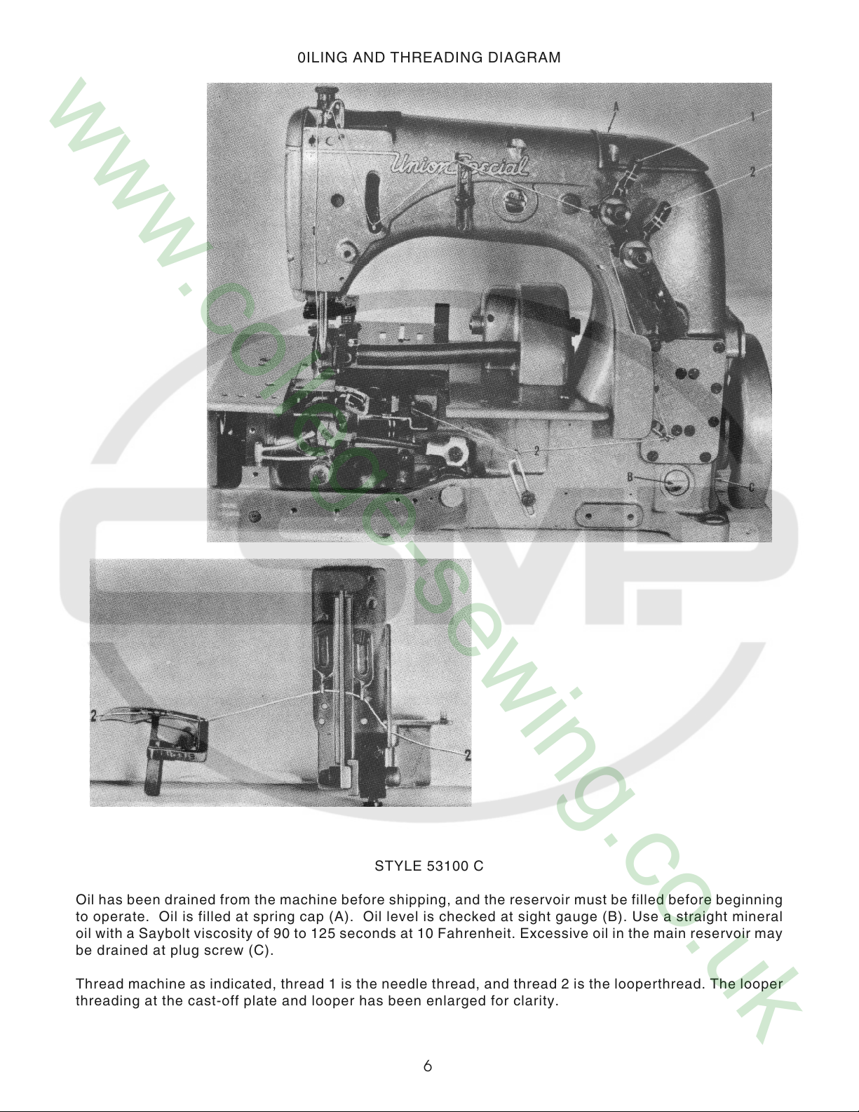
STYLE 53100 C
Oil has been drained from the machine before shipping, and the reservoir must be filled before beginning
to operate. Oil is filled at spring cap (A). Oil level is checked at sight gauge (B). Use a straight mineral
oil with a Saybolt viscosity of 90 to 125 seconds at 10 Fahrenheit. Excessive oil in the main reservoir may
be drained at plug screw (C).
Thread machine as indicated, thread 1 is the needle thread, and thread 2 is the looperthread. The looper
threading at the cast-off plate and looper has been enlarged for clarity.
6
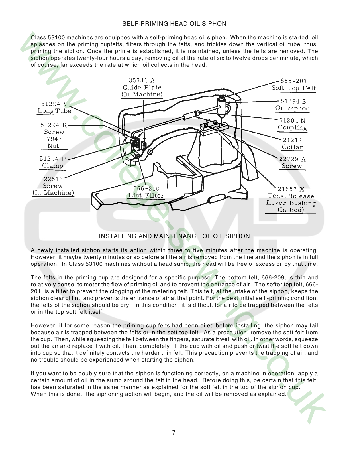
SELF-PRIMING HEAD OIL SIPHON
Class 53100 machines are equipped with a self-priming head oil siphon. When the machine is started, oil
splashes on the priming cupfelts, filters through the felts, and trickles down the vertical oil tube, thus,
priming the siphon. Once the prime is established, it is maintained, unless the felts are removed. The
siphon operates twenty-four hours a day, removing oil at the rate of six to twelve drops per minute, which
of course, far exceeds the rate at which oil collects in the head.
INSTALLING AND MAINTENANCE OF OIL SIPHON
A newly installed siphon starts its action within three to five minutes after the machine is operating.
However, it maybe twenty minutes or so before all the air is removed from the line and the siphon is in full
operation. In Class 53100 machines without a head sump, the head will be free of excess oil by that time.
The felts in the priming cup are designed for a specific purpose. The bottom felt, 666-209, is thin and
relatively dense, to meter the flow of priming oil and to prevent the entrance of air. The softer top felt, 666-
201, is a filter to prevent the clogging of the metering felt. This felt, at the intake of the siphon, keeps the
siphon clear of lint, and prevents the entrance of air at that point. For the best initial self -priming condition,
the felts of the siphon should be dry. In this condition, it is difficult for air to be trapped between the felts
or in the top soft felt itself.
However, if for some reason the priming cup felts had been oiled before installing, the siphon may fail
because air is trapped between the felts or in the soft top felt. As a precaution, remove the soft felt from
the cup. Then, while squeezing the felt between the fingers, saturate it well with oil. In other words, squeeze
out the air and replace it with oil. Then, completely fill the cup with oil and push or twist the soft felt down
into cup so that it definitely contacts the harder thin felt. This precaution prevents the trapping of air, and
no trouble should be experienced when starting the siphon.
If you want to be doubly sure that the siphon is functioning correctly, on a machine in operation, apply a
certain amount of oil in the sump around the felt in the head. Before doing this, be certain that this felt
has been saturated in the same manner as explained for the soft felt in the top of the siphon cup.
When this is done., the siphoning action will begin, and the oil will be removed as explained.
7
INSTRUCTIONS FOR MECHANICS
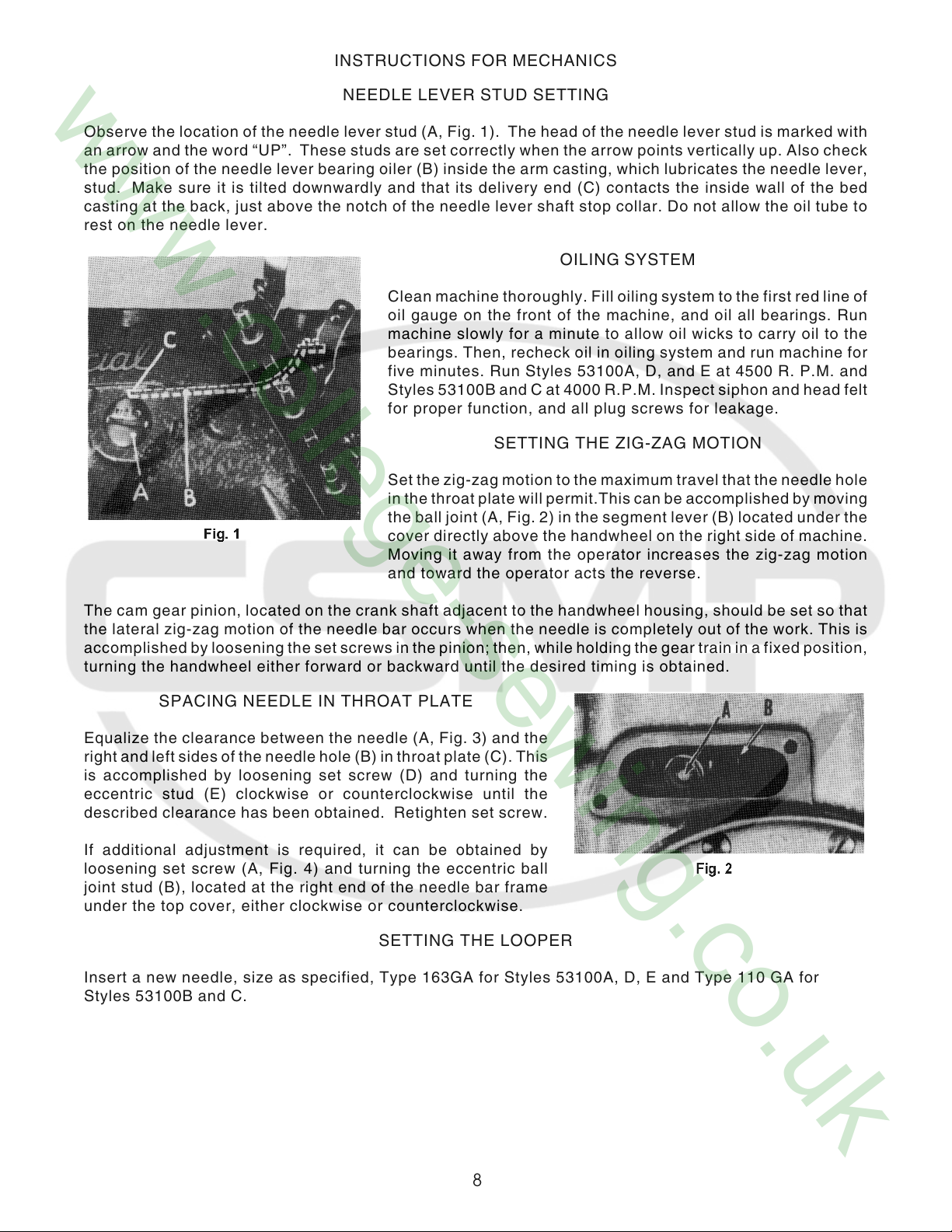
NEEDLE LEVER STUD SETTING
Observe the location of the needle lever stud (A, Fig. 1). The head of the needle lever stud is marked with
an arrow and the word “UP”. These studs are set correctly when the arrow points vertically up. Also check
the position of the needle lever bearing oiler (B) inside the arm casting, which lubricates the needle lever,
stud. Make sure it is tilted downwardly and that its delivery end (C) contacts the inside wall of the bed
casting at the back, just above the notch of the needle lever shaft stop collar. Do not allow the oil tube to
rest on the needle lever.
OILING SYSTEM
Clean machine thoroughly. Fill oiling system to the first red line of
oil gauge on the front of the machine, and oil all bearings. Run
machine slowly for a minute to allow oil wicks to carry oil to the
bearings. Then, recheck oil in oiling system and run machine for
five minutes. Run Styles 53100A, D, and E at 4500 R. P.M. and
Styles 53100B and C at 4000 R.P.M. Inspect siphon and head felt
for proper function, and all plug screws for leakage.
SETTING THE ZIG-ZAG MOTION
Set the zig-zag motion to the maximum travel that the needle hole
in the throat plate will permit.This can be accomplished by moving
the ball joint (A, Fig. 2) in the segment lever (B) located under the
cover directly above the handwheel on the right side of machine.
Moving it away from the operator increases the zig-zag motion
and toward the operator acts the reverse.
The cam gear pinion, located on the crank shaft adjacent to the handwheel housing, should be set so that
the lateral zig-zag motion of the needle bar occurs when the needle is completely out of the work. This is
accomplished by loosening the set screws in the pinion; then, while holding the gear train in a fixed position,
turning the handwheel either forward or backward until the desired timing is obtained.
SPACING NEEDLE IN THROAT PLATE
Equalize the clearance between the needle (A, Fig. 3) and the
right and left sides of the needle hole (B) in throat plate (C). This
is accomplished by loosening set screw (D) and turning the
eccentric stud (E) clockwise or counterclockwise until the
described clearance has been obtained. Retighten set screw.
If additional adjustment is required, it can be obtained by
loosening set screw (A, Fig. 4) and turning the eccentric ball
joint stud (B), located at the right end of the needle bar frame
under the top cover, either clockwise or counterclockwise.
SETTING THE LOOPER
Insert a new needle, size as specified, Type 163GA for Styles 53100A, D, E and Type 110 GA for
Styles 53100B and C.
8
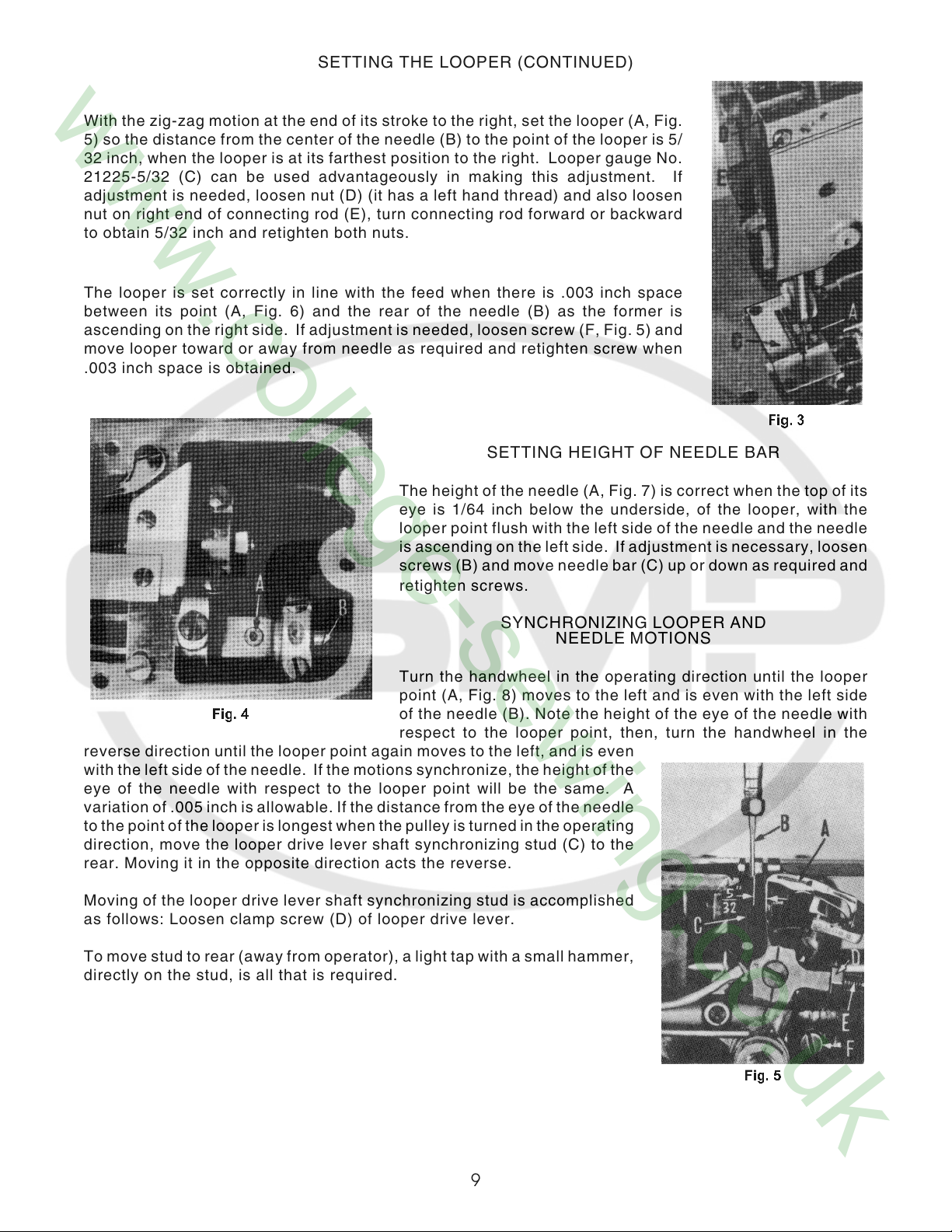
SETTING THE LOOPER (CONTINUED)
With the zig-zag motion at the end of its stroke to the right, set the looper (A, Fig.
5) so the distance from the center of the needle (B) to the point of the looper is 5/
32 inch, when the looper is at its farthest position to the right. Looper gauge No.
21225-5/32 (C) can be used advantageously in making this adjustment. If
adjustment is needed, loosen nut (D) (it has a left hand thread) and also loosen
nut on right end of connecting rod (E), turn connecting rod forward or backward
to obtain 5/32 inch and retighten both nuts.
The looper is set correctly in line with the feed when there is .003 inch space
between its point (A, Fig. 6) and the rear of the needle (B) as the former is
ascending on the right side. If adjustment is needed, loosen screw (F, Fig. 5) and
move looper toward or away from needle as required and retighten screw when
.003 inch space is obtained.
SETTING HEIGHT OF NEEDLE BAR
The height of the needle (A, Fig. 7) is correct when the top of its
eye is 1/64 inch below the underside, of the looper, with the
looper point flush with the left side of the needle and the needle
is ascending on the left side. If adjustment is necessary, loosen
screws (B) and move needle bar (C) up or down as required and
retighten screws.
SYNCHRONIZING LOOPER AND
Turn the handwheel in the operating direction until the looper
point (A, Fig. 8) moves to the left and is even with the left side
of the needle (B). Note the height of the eye of the needle with
respect to the looper point, then, turn the handwheel in the
reverse direction until the looper point again moves to the left, and is even
with the left side of the needle. If the motions synchronize, the height of the
eye of the needle with respect to the looper point will be the same. A
variation of .005 inch is allowable. If the distance from the eye of the needle
to the point of the looper is longest when the pulley is turned in the operating
direction, move the looper drive lever shaft synchronizing stud (C) to the
rear. Moving it in the opposite direction acts the reverse.
Moving of the looper drive lever shaft synchronizing stud is accomplished
as follows: Loosen clamp screw (D) of looper drive lever.
To move stud to rear (away from operator), a light tap with a small hammer,
directly on the stud, is all that is required.
NEEDLE MOTIONS
9
SYNCHRONIZING LOOPER AND
NEEDLE MOTIONS (CONTINUED)
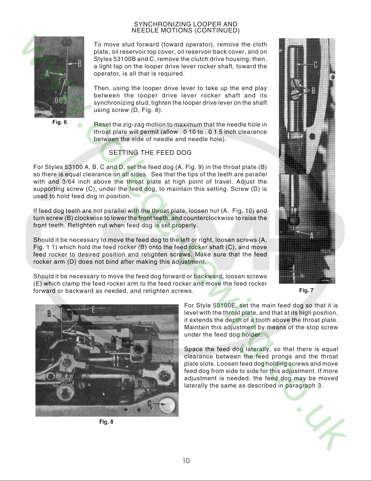
To move stud forward (toward operator), remove the cloth
plate, oil reservoir top cover, oil reservoir back cover, and on
Styles 53100B and C, remove the clutch drive housing; then,
For Styles 53100 A, B, C and D, set the feed dog (A, Fig. 9) in the throat plate (B)
so there is equal clearance on all sides. See that the tips of the teeth are parallel
with and 3/64 inch above the throat plate at high point of travel. Adjust the
supporting screw (C), under the feed dog, to maintain this setting. Screw (D) is
used to hold feed dog in position.
a light tap on the looper drive lever rocker shaft, toward the
operator, is all that is required.
Then, using the looper drive lever to take up the end play
between the looper drive lever rocker shaft and its
synchronizing stud, tighten the looper drive lever on the shaft
using screw (D, Fig. 8).
Reset the zig-zag motion to maximum that the needle hole in
throat plate will permit (allow . 0 10 to . 0 1 5 inch clearance
between the side of needle and needle hole).
SETTING THE FEED DOG
If feed dog teeth are not parallel with the throat plate, loosen nut (A. Fig. 10) and
turn screw (B) clockwise to lower the front teeth, and counterclockwise to raise the
front teeth. Retighten nut when feed dog is set properly.
Should it be necessary to move the feed dog to the left or right, loosen screws (A,
Fig. 1 1) which hold the feed rocker (B) onto the feed rocker shaft (C), and move
feed rocker to desired position and retighten screws. Make sure that the feed
rocker arm (D) does not bind after making this adjustment.
Should it be necessary to move the feed dog forward or backward, loosen screws
(E) which clamp the feed rocker arm to the feed rocker and move the feed rocker
forward or backward as needed, and retighten screws.
For Style 53100E, set the main feed dog so that it is
level with the throat plate, and that at its high position,
it extends the depth of a tooth above the throat plate.
Maintain this adjustment by means of the stop screw
under the feed dog holder.
Space the feed dog laterally, so that there is equal
clearance between the feed prongs and the throat
plate slots. Loosen feed dog holding screws and move
feed dog from side to side for this adjustment. If more
adjustment is needed, the feed dog may be moved
laterally the same as described in paragraph 3.
10
SETTING THE FEED DOG (CONTINUED)
With an average stitch length setting, equalize the travel of the feed dog so that, at both ends of its travel,
it is equidistant from the ends of the throat plate slot. Make this adjustment the same as described in
paragraph 4.
Set the height of the differential feed dog to correspond with that of the main feed dog by moving it up or
down in its holder.
Turn handwheel in operating direction until the feed dog is
at its farthest point of travel to the rear, and set the
differential feed so that there is I/ 64 inch clearance
between the center row of teeth and the end of the throat
plate slot. This is done by loosening the two headless
screws which clamp the shank of the differential feed bar.
The throat plate support will have to be removed for
access. Also level the feed during this adjustment.
Set the front stop for the intermittent differential feed lever as far forward in its slot as it will go. Turn the
handwheel in operating direction until the feed dogs are descending. When the tips of their teeth are flush
with the top of the throat plate, manipulate the differential feed control lever up and down. At this point, there
should be no more than 1/ 64 inch motion in the differential feed dog. If more motion exists, loosen the three
screws which hold the segment slot plate to the feed rocker, and manipulate the position of the slot plate
until excess motion of the differential feed dog is eliminated. An offset screw driver will be required for this
adjustment.
Continue to turn the handwheel in operating direction until the feed dog reaches its most forward point of
travel. Depress the differential feed control lever until the front of the differential feed dog just clears the
throat plate slot by I/ 64 inch and set the rear stop for the differential feed control lever against the lever
pointer at this position.
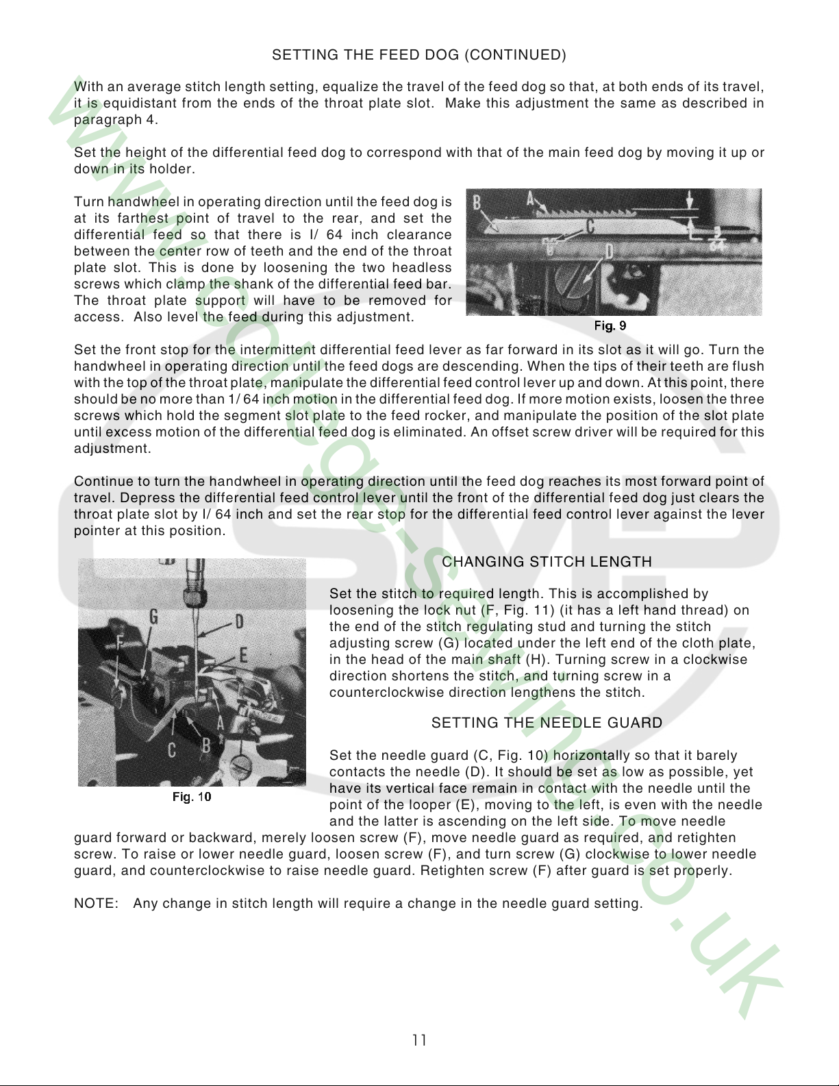
CHANGING STITCH LENGTH
Set the stitch to required length. This is accomplished by
loosening the lock nut (F, Fig. 11) (it has a left hand thread) on
the end of the stitch regulating stud and turning the stitch
adjusting screw (G) located under the left end of the cloth plate,
in the head of the main shaft (H). Turning screw in a clockwise
direction shortens the stitch, and turning screw in a
counterclockwise direction lengthens the stitch.
SETTING THE NEEDLE GUARD
Set the needle guard (C, Fig. 10) horizontally so that it barely
contacts the needle (D). It should be set as low as possible, yet
have its vertical face remain in contact with the needle until the
point of the looper (E), moving to the left, is even with the needle
and the latter is ascending on the left side. To move needle
guard forward or backward, merely loosen screw (F), move needle guard as required, and retighten
screw. To raise or lower needle guard, loosen screw (F), and turn screw (G) clockwise to lower needle
guard, and counterclockwise to raise needle guard. Retighten screw (F) after guard is set properly.
NOTE: Any change in stitch length will require a change in the needle guard setting.
11

SYNCHRONIZATION OF THE UPPER ROLLER FEED
On Styles 53100B and C, synchronize the upper roller feed (E, Fig. 8) with the lower feed dog. This is
accomplished by removing the plug screw (A, Fig. 12) from the top of the housing (B) located at the
rear right side of the machine. Then, after noting the direction the shaft journaled in the housing
rotates, loosen the clamp screws in the gear hub, made accessible by removal of the plug screw.
Turning this back shaft in its operating direction causes the top roller feed to start turning sooner, and
turning the shaft backward causes the puller roll to start turning later.
The travel of the top roller feed is adjusted at the left end of this back shaft. Its adjustment is identical
to the stitch length adjustment mentioned in the adjusting instructionsunder ”CHANGING STITCH
LENGTH”. It has the same adjusting screw and left hand thread lock nut arrangement. When loosening
or tightening the lock nut, do not hold the handwheel to maintain shaft position, as the gear on the
crankshaft might shift, which would make it necessary to re-time the machine. Instead, insert a screw
driver through the access hole (C) in the top of the gear housing at the left end and engage the
adjusting screw. By holding the screw driver in this manner, the lock nut may be loosened or tightened
without disturbing the gear setting.
NOTE: The adjustment just mentioned and the regulation of the
pressure on the presser foot are very important to the
appearance of the finished seam.
THREADING
Draw looper and needle threads into the machine and start
operating on a piece of fabric. Refer to threading diagram on Page
8, for manner of threading these machines.
12
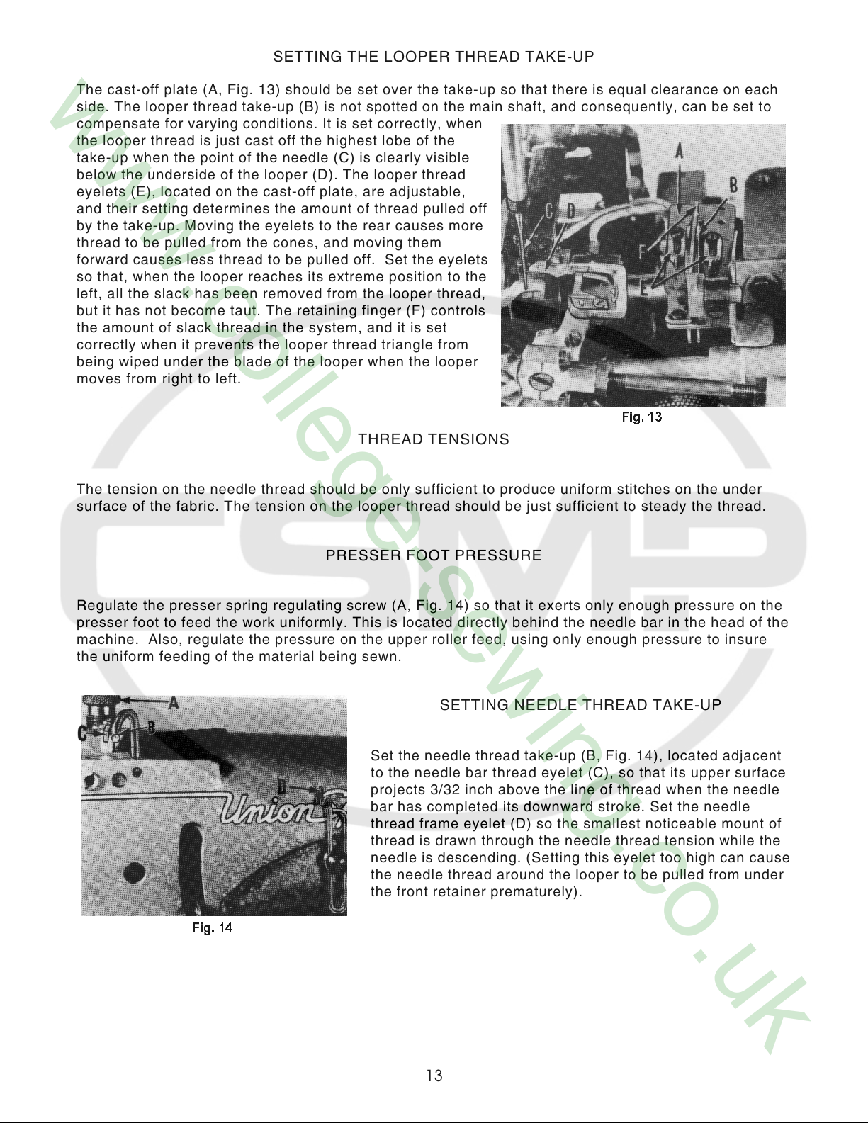
SETTING THE LOOPER THREAD TAKE-UP
The cast-off plate (A, Fig. 13) should be set over the take-up so that there is equal clearance on each
side. The looper thread take-up (B) is not spotted on the main shaft, and consequently, can be set to
compensate for varying conditions. It is set correctly, when
the looper thread is just cast off the highest lobe of the
take-up when the point of the needle (C) is clearly visible
below the underside of the looper (D). The looper thread
eyelets (E), located on the cast-off plate, are adjustable,
and their setting determines the amount of thread pulled off
by the take-up. Moving the eyelets to the rear causes more
thread to be pulled from the cones, and moving them
forward causes less thread to be pulled off. Set the eyelets
so that, when the looper reaches its extreme position to the
left, all the slack has been removed from the looper thread,
but it has not become taut. The retaining finger (F) controls
the amount of slack thread in the system, and it is set
correctly when it prevents the looper thread triangle from
being wiped under the blade of the looper when the looper
moves from right to left.
THREAD TENSIONS
The tension on the needle thread should be only sufficient to produce uniform stitches on the under
surface of the fabric. The tension on the looper thread should be just sufficient to steady the thread.
PRESSER FOOT PRESSURE
Regulate the presser spring regulating screw (A, Fig. 14) so that it exerts only enough pressure on the
presser foot to feed the work uniformly. This is located directly behind the needle bar in the head of the
machine. Also, regulate the pressure on the upper roller feed, using only enough pressure to insure
the uniform feeding of the material being sewn.
SETTING NEEDLE THREAD TAKE-UP
Set the needle thread take-up (B, Fig. 14), located adjacent
to the needle bar thread eyelet (C), so that its upper surface
projects 3/32 inch above the line of thread when the needle
bar has completed its downward stroke. Set the needle
thread frame eyelet (D) so the smallest noticeable mount of
thread is drawn through the needle thread tension while the
needle is descending. (Setting this eyelet too high can cause
the needle thread around the looper to be pulled from under
the front retainer prematurely).
13
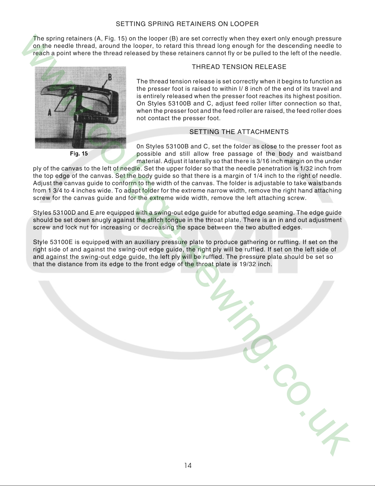
SETTING SPRING RETAINERS ON LOOPER
The spring retainers (A, Fig. 15) on the looper (B) are set correctly when they exert only enough pressure
on the needle thread, around the looper, to retard this thread long enough for the descending needle to
reach a point where the thread released by these retainers cannot fly or be pulled to the left of the needle.
The thread tension release is set correctly when it begins to function as
the presser foot is raised to within I/ 8 inch of the end of its travel and
is entirely released when the presser foot reaches its highest position.
On Styles 53100B and C, adjust feed roller lifter connection so that,
when the presser foot and the feed roller are raised, the feed roller does
not contact the presser foot.
0n Styles 53100B and C, set the folder as close to the presser foot as
possible and still allow free passage of the body and waistband
material. Adjust it laterally so that there is 3/16 inch margin on the under
ply of the canvas to the left of needle. Set the upper folder so that the needle penetration is 1/32 inch from
the top edge of the canvas. Set the body guide so that there is a margin of 1/4 inch to the right of needle.
Adjust the canvas guide to conforrn to the width of the canvas. The folder is adjustable to take waistbands
from 1 3/4 to 4 inches wide. To adapt folder for the extreme narrow width, remove the right hand attaching
screw for the canvas guide and for the extreme wide width, remove the left attaching screw.
Styles 53100D and E are equipped with a swing-out edge guide for abutted edge seaming. The edge guide
should be set down snugly against the stitch tongue in the throat plate. There is an in and out adjustment
screw and lock nut for increasing or decreasing the space between the two abutted edges.
Style 53100E is equipped with an auxiliary pressure plate to produce gathering or ruffling. If set on the
right side of and against the swing-out edge guide, the right ply will be ruffled. If set on the left side of
and against the swing-out edge guide, the left ply will be ruffled. The pressure plate should be set so
that the distance from its edge to the front edge of the throat plate is 19/32 inch.
THREAD TENSION RELEASE
SETTING THE ATTACHMENTS
14
 Loading...