

Union Special 100L GR Parts Book
STYLES
53700B
53800B
ADJUSTING INSTRUCTIONS AND
ILLUSTRATED PARTS LIST
STREAMLINED
FIFTY THOUSAND SERIES
CATALOG NO.
100L-GR
FIRST EDITION
01/23/09
MANUAL NO. 100L-GR ADJUSTING INSTRUCTIONS AND LLUSTRATED PARTS LIST FOR 53700 /53800
SERIES MACHINES
First Edition Copyright 2008
BY
The new streamlined Class 53700 and 53800 machines bring to the automobile upholstery and seat cover industry new
styling, improved lubrication, and light running high speed performance. Enclosed type oiling system for looper drive
eccentric, upper feed driving eccentric, and needle lever crank have substantially increased the speed of these
machines. The almost entirely automatic lubrication system makes maintenance simple. All parts are made by precision
methods insuring complete interchangeability.
It is our constant aim to furnish carefully prepared information which will enable our customer to secure all possible
economies from the use of Union Special sewing machines. The following pages illustrate and describe the parts for the
styles in Classes 53700 and 53800.
Union Special representatives will be found in all manufacturing centers, ready to cooperate with you to plan and estimate
requirements.
Union Special Corporation Rights Reserved In All Countries
Printed in U.S.A. Jan 2008
FOREWORD
2
CONTENTS
IDENTIFICATION OF MACHINE .................................................................................................................................................................3
APPLICATION OF CATALOG ...................................................................................................................................................................3
STYLES OF MACHINE ................................................................................................................................................................................3
NEEDLES .................................................................................................................................................................................................... 4
ORDERING REPAIR PARTS ........................................................................................................................................................................4
ORDERING REPAIR PARTS (CONTINUED) ................................................................................................................................................ 5
IDENTIFYING PARTS ................................................................................................................................................................................... 5
USE GENUINE NEEDLES AND REPAIR PARTS ........................................................................................................................................... 5
TERMS ........................................................................................................................................................................................................ 5
OILING AND THREADING ......................................................................................................................................................................... 5
0ILING AND THREADING DIAGRAM ....................................................................................................................................................... 6
SELF-PRIMING HEAD OIL SIPHON ............................................................................................................................................................ 7
INSTALLING AND MAINTENANCE OF OIL SIPHON ................................................................................................................................. 7
INSTRUCTIONS FOR MECHANICS ............................................................................................................................................................ 8
NEEDLE LEVER STUD SETTING ...................................................................................................................................................................8
OILING SYSTEM ......................................................................................................................................................................................... 8
SETTING THE ZIG-ZAG MOTION ............................................................................................................................................................... 8
SPACING NEEDLE IN THROAT PLATE .......................................................................................................................................................8
SETTING THE LOOPER ...............................................................................................................................................................................8
SETTING THE LOOPER (CONTINUED) .......................................................................................................................................................9
SETTING HEIGHT OF NEEDLE BAR ............................................................................................................................................................. 9
SYNCHRONIZING LOOPER AND ............................................................................................................................................................. 9
NEEDLE MOTIONS ..................................................................................................................................................................................... 9
SYNCHRONIZING LOOPER AND ........................................................................................................................................................... 10
NEEDLE MOTIONS (CONTINUED) ..........................................................................................................................................................10
SETTING THE FEED DOG ......................................................................................................................................................................... 10
SETTING THE FEED DOG (CONTINUED) .................................................................................................................................................11
CHANGING STITCH LENGTH .................................................................................................................................................................. 11
SETTING THE NEEDLE GUARD ................................................................................................................................................................. 11
SYNCHRONIZATION OF THE UPPER ROLLER FEED ................................................................................................................................ 12
THREADING .............................................................................................................................................................................................12
SETTING THE LOOPER THREAD TAKE-UP ................................................................................................................................................13
THREAD TENSIONS .................................................................................................................................................................................. 13
PRESSER FOOT PRESSURE ....................................................................................................................................................................... 13
SETTING NEEDLE THREAD TAKE-UP ........................................................................................................................................................ 13
SETTING SPRING RETAINERS ON LOOPER .............................................................................................................................................14
THREAD TENSION RELEASE .....................................................................................................................................................................14
SETTING THE ATTACHMENTS ................................................................................................................................................................... 14
MAIN FRAME, CAST-OFF PLATE, MISCELLANEOUS COVERS AND PLATES ......................................................................................... 17
CLOTH PLATES, CLOTH PLATE COVERS, MISCELLANEOUS AND ATTACHMENTS .............................................................................. 19
MAIN FRAME, BUSHINGS AND MISCELLANEOUS OILING PARTS ........................................................................................................ 21
FOR STYLES 53100B AND C ONLY CLUTCH ASSEMBLY, CLUTCH DRIVE SHAFT GEAR AND HOUSING ASSEMBLY .......................... 23
FOR STYLES 53100B AND C ONLY CLUTCH ASSEMBLY, CLUTCH DRIVE SHAFT GEAR AND HOUSING ASSEMBLY .......................... 25
CRANKSHAFT, NEEDLE LEVER AND LOOPER DRIVING PARTS ............................................................................................................ 27
CRANKSHAFT, NEEDLE LEVER AND LOOPER DRIVING PARTS ............................................................................................................ 29
LOOPER ROCKER AND CONNECTING ROD PARTS ............................................................................................................................ 31
MAIN SHAFT AND FEED MECHANISM ................................................................................................................................................... 33
FOR STYLE 53100E ONLY MAIN SHAFT AND FEED MECHANISM ......................................................................................................... 35
THREAD TENSION AND FOOT LIFTER LEVER PARTS ............................................................................................................................... 37
FEED DOGS, THROAT PLATES AND PRESSER FEET ................................................................................................................................ 39
THREAD STAND, KNEE PRESS AND TAPE REEL PARTS ........................................................................................................................... 41
3

IDENTIFICATION OF MACHINE
Each UNION SPECIAL machine is identified by a Style number which is stamped into the name plate on
the machine. Style numbers are classified as standard and special. Those which are standard have one
or more letters suffixed to the class number, but never contain the letter "Z". Example : "53700B". Style
numbers containing the letter "Z" are special. When only minor changes are made in a standard machine,
a "Z" is merely suffixed to the standard style number. Example: "53700BZ".
Styles of machines similar in construction are grouped under a class number which differs from the style
number, in that it contains no letters. Example: “53700”.
APPLICATION OF CATALOG
This catalog applies specifically to the standard Styles of machines as listed herein. It can also be
applied with discretion to some Special Styles of machines in this class.
STYLES OF MACHINE IN CLASSES 53700 AND 53800
Streamlined Enclosed Type Flat Bed, High Throw, Power Driven Upper Running Feed, with Alternating
Presser Foot Action, Lower Feed, Single Reservoir Enclosed Automatic Lubricating System and Filter
Type Oil Return Pump, Lateral Looper Travel, 1 1/2 Inch Needle Travel, Work Space to Right of
Needle, 7 3/4 Inches.
53700B For seaming operations on automobile upholstery and similar articles made from medium
heavy to heavy weight materials, one needle machine, four to seven stitches per inch, seam
specification 401-SSa-1. Maximum recomended speed 3300 R.P.M.
53800B For seaming operations on automobile upholstery, also on fiber, fabric, and plastic auto-
mobile seat covers and for similar operations on medium heavy to heavy weight materials
with or without corded leatherette or plastic piping, two needle machine, four to seven
stitches per inch, seam specification 401-SSa-2. Maximum recomended speed 3300 R.P.M.
NEEDLES
Each UNION SPECIAL needle has both a type number and a size number. The type number denotes the
kind of shank, point, length, groove, finish and other details. The size number, stamped on the needle
shank, denotes the largest diameter of blade measured in thousandths of an inch midway between the
shank and the eye. Collectively, type number and the size number is the complete symbol.
Standard needle for Styles 53700 B, and 53800B is Type 147 GS. It is a round shank, round point, long,
double groove, ball eye, spotted, short point, struck groove, undersize eye and grooves, one step reduction,
chromium plated needle and is available in sizes 080/032, 090/036, 100/040, 110/044, 125/049, 140/054,
150/060, 170/067.
Also available for styles 53700B and 53800B is Type 143GS. It is a round shank, round point, No. 2 bag,
double groove, spotted, chromium plated needle and is available in sizes 140/054, 150/060, 170/067.
To have needle orders promptly and accurately filled, an empty package,a sample needle, or the type and
size number should be forwarded. Use description on label. A complete order would read: "11000
Needles,Type 147 GS, Size 140/054".
Selection of the proper needle size should be determined by the size of thread used. Thread should pass
freely through needle eye in order to produce a good stitch formation.
4
ORDERING REPAIR PARTS
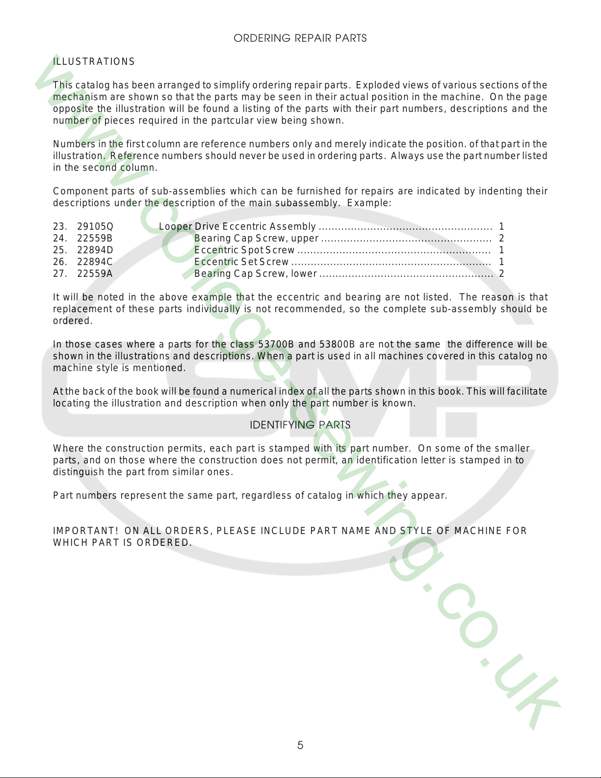
ILLUSTRATIONS
This catalog has been arranged to simplify ordering repair parts. Exploded views of various sections of the
mechanism are shown so that the parts may be seen in their actual position in the machine. On the page
opposite the illustration will be found a listing of the parts with their part numbers, descriptions and the
number of pieces required in the partcular view being shown.
Numbers in the first column are reference numbers only and merely indicate the position. of that part in the
illustration. Reference numbers should never be used in ordering parts. Always use the part number listed
in the second column.
Component parts of sub-assemblies which can be furnished for repairs are indicated by indenting their
descriptions under the description of the main subassembly. Example:
23. 29105Q Looper Drive Eccentric Assembly ...................................................... 1
24. 22559B Bearing Cap Screw, upper ..................................................... 2
25. 22894D Eccentric Spot Screw ............................................................ 1
26. 22894C Eccentric Set Screw .............................................................. 1
27. 22559A Bearing Cap Screw, lower ...................................................... 2
It will be noted in the above example that the eccentric and bearing are not listed. The reason is that
replacement of these parts individually is not recommended, so the complete sub-assembly should be
ordered.
In those cases where a parts for the class 53700B and 53800B are not the same the difference will be
shown in the illustrations and descriptions. When a part is used in all machines covered in this catalog no
machine style is mentioned.
At the back of the book will be found a numerical index of all the parts shown in this book. This will facilitate
locating the illustration and description when only the part number is known.
IDENTIFYING PARTS
Where the construction permits, each part is stamped with its part number. On some of the smaller
parts, and on those where the construction does not permit, an identification letter is stamped in to
distinguish the part from similar ones.
Part numbers represent the same part, regardless of catalog in which they appear.
IMPORTANT! ON ALL ORDERS, PLEASE INCLUDE PART NAME AND STYLE OF MACHINE FOR
WHICH PART IS ORDERED.
5
USE GENUINE NEEDLES AND REPAIR PARTS
Success in the operation of these machines can be secured only with genuine UNION SPECIAL
Needles and Repair Parts as furnished by the Union Special Corporation, its subsidiaries and
authorized distributors. They are designed according to the most approved scientific principles, and are
made with the utmost precision. Maximum efficiency and durability are assured.
Genuine needles are packaged with labels marked Union Special Genuine repair parts are stamped
with the Union Special trademark, U S Emblem. Each trademark is your guarantee of the highest
quality in materials and workmanship.
TERMS
Prices are strictly net cash and are subject to change without notice. All shipments are forwarded f.o.b.
shipping point. Parcel Post shipments are insured unless otherwise directed. A charge is made to
cover the postage and insurance.
OILING AND THREADING
The oil has been drained from the machine before shipping, and the reservoir must be filled before
beginning to operate. Use a straight mineral oil with a Saybolt viscosity of 90 to 125 seconds at 1000
Fahrenheit.
Oil is filled at the spring cap in the top cover, and the oil level is checked at the sight gauge on the
front of the machine. The oil level should be maintained between the red lines on the gauge. The
capacity of the oil reservoir is 12 ounces.
The lubrication, which is almost entirely automatic, requires a minimum of manual oiling. The oiling
diagram on the opposite page is self-explanatory.
The main reservoir supplies oil to the looper drive eccentric, upper running feed drive eccentric, needle
lever crank: and the supply is registered at the front gauge. The entire lower mechanism is served
through a system of channels and wicks in the main frame by this reservoir.
A daily check before the morning start should be made and oil added if required. Oil which has gone
through the machine is filtered and pumped back into the main reservoir, making too frequent oilings
unnecessary. Excessive oil in the main reservoir may be drained at the plug screw in the main frame
directly under the handwheel.
The accompanying diagram also shows the threading of the single needle Class 53700B machine.
Threading of the two needle Class 53800B machine is substantially the same.
6
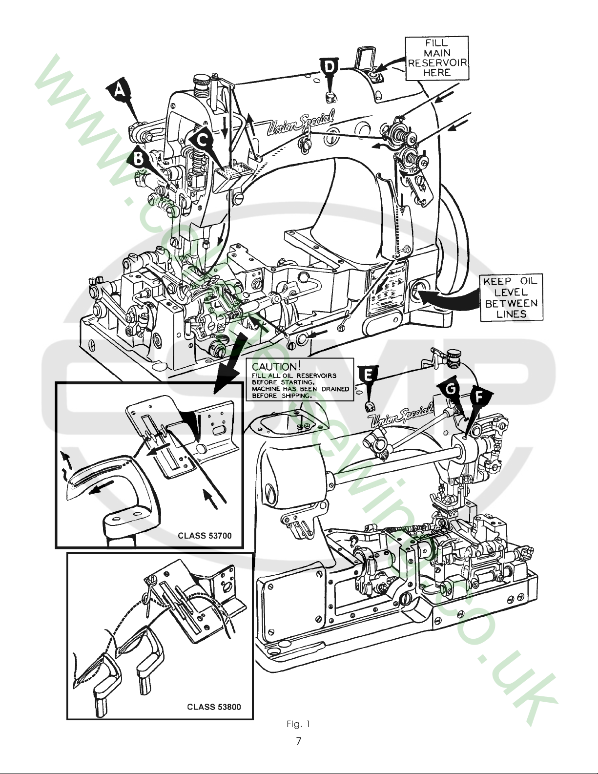
Fig. 1
7
SYNCHRONIZING LOOPER AND NEEDLE MOTIONS
Check the synchronization of the looper and needle motions, using gauge No. T34 and plate No.
21227AD as follows:
Insert the pin, which is included with the gauge, in the looper rocker for 2 needle machine use right
looper. Place the gauge plate on the throat plate seat using the throatplate screws for attaching. Place
the indicator portion of the gauge in the needle thread take-up wire hole with the pointer to the right,
but do not tighten the set screw at this time. Turn the handwheel in the operating direction until the pin
in the looper rocker contacts the edge of the gauge plate and set the indicator so that the left end of
the pointer rests against the top of the needle bar and the right end of the pointer rests at “O”. Tighten
the set screw and note indicator reading. Turn the handwheel in the reverse direction until the pin again
contacts the plate. If the motions are in synchronization, the pointer of the indicator will return to the
same reading. A variation of one graduation on the scale is allowable. If the reading is higher on the
scale when the handwheel is turned in the operating direction, the looper drive lever rocker will have to
be moved to the rear. If the reading is lower, the rocker will have to be moved to the front.
NOTE: If gauge No. 21227AD is not available, synchronization may be checked as follows:
Insert the looper in the looper rocker and turn the handwheel in the operating direction until the point of
the looper, moving to the left, is even with the left side of the needle. Note the height of the eye of the
needle with respect to the looper point, then turn handwheel in the reverse direction until the looper
point again moves to the left and is even with the left side of the needle. If the motions synchronize, the
height of the eye of the needle with respect to the looper point will be the same. A variation of .005
inch is allowable. If the distance from the eye of the needle to the point of the looper is greater when
the handwheel is turned in the operating direction, move the looper drive lever rocker to the rear.
Moving it in the opposite direction acts the reverse. Moving of the looper drive lever rocker is accom-
plished as follows:
Remove the cloth plate, throat plate support, oil reservoir top
cover and loosen the screws in the looper drive eccentric mecha-
nism and move the eccentric as far to the right as it will go. Drive
the rear bushing to the front or the middle bushing to the rear, as
required. CAUTION: To avoid distorting the parts, remove the plug
screw in the bed behind the rear bushing before driving to the
front and place a horse shoe shaped metal washer approximately
1/16 inch thick between the looper drive lever and adjacent
bushing when driving the bushing to the rear. Correctly reposition
the looper drive eccentric mechanism (per spot screws) and
tighten all screws securely.
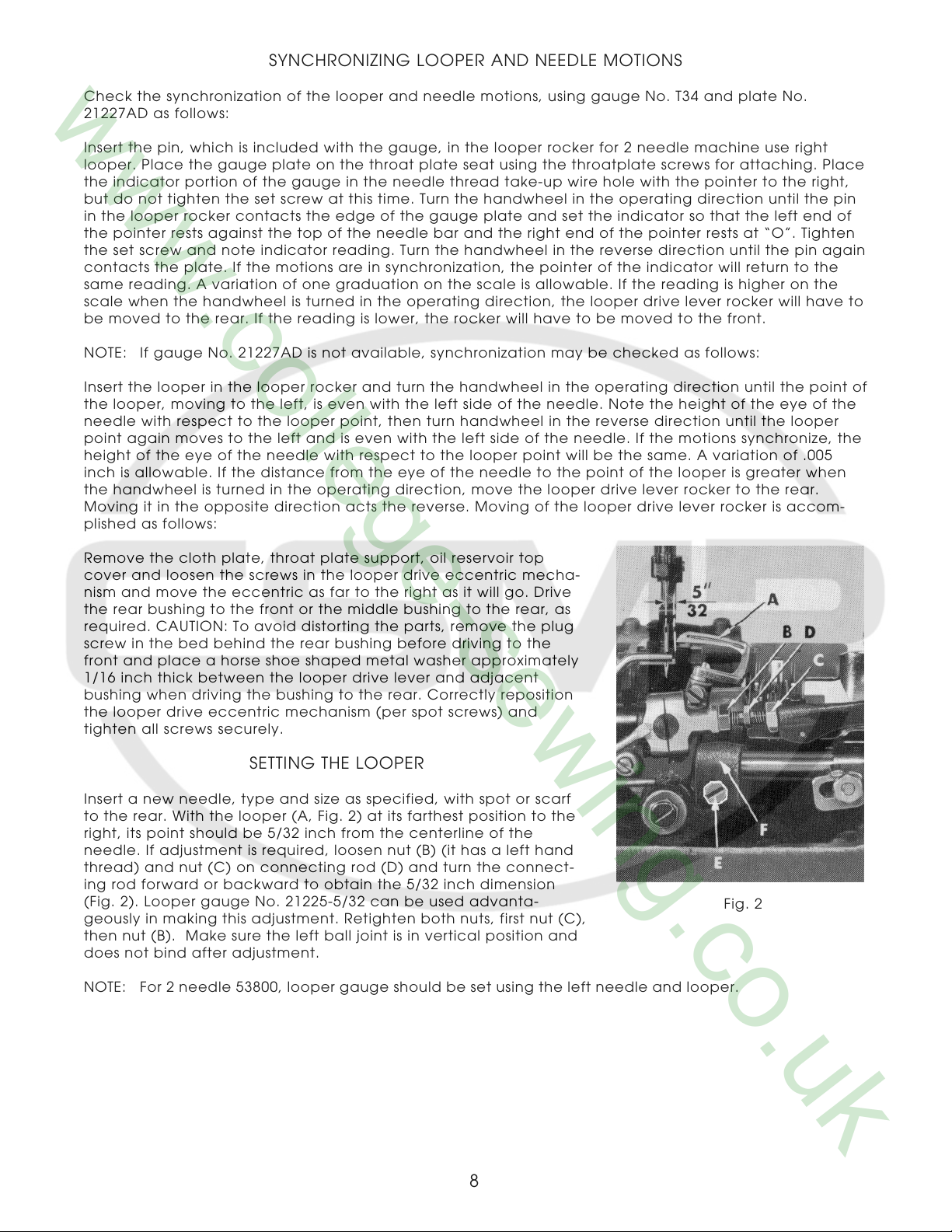
SETTING THE LOOPER
Insert a new needle, type and size as specified, with spot or scarf
to the rear. With the looper (A, Fig. 2) at its farthest position to the
right, its point should be 5/32 inch from the centerline of the
needle. If adjustment is required, loosen nut (B) (it has a left hand
thread) and nut (C) on connecting rod (D) and turn the connect-
ing rod forward or backward to obtain the 5/32 inch dimension
(Fig. 2). Looper gauge No. 21225-5/32 can be used advanta-
geously in making this adjustment. Retighten both nuts, first nut (C),
then nut (B). Make sure the left ball joint is in vertical position and
does not bind after adjustment.
NOTE: For 2 needle 53800, looper gauge should be set using the left needle and looper.
Fig. 2
8
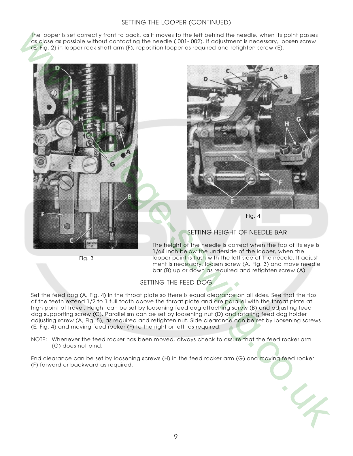
SETTING THE LOOPER (CONTINUED)
The looper is set correctly front to back, as it moves to the left behind the needle, when its point passes
as close as possible without contacting the needle (.001-.002). If adjustment is necessary, loosen screw
(E, Fig. 2) in looper rock shaft arm (F), reposition looper as required and retighten screw (E).
Fig. 4
SETTING HEIGHT OF NEEDLE BAR
The height of the needle is correct when the top of its eye is
1/64 inch below the underside of the looper, when the
Fig. 3
Set the feed dog (A, Fig. 4) in the throat plate so there is equal clearance on all sides. See that the tips
of the teeth extend 1/2 to 1 full tooth above the throat plate and are parallel with the throat plate at
high point of travel. Height can be set by loosening feed dog attaching screw (B) and adjusting feed
dog supporting screw (C). Parallelism can be set by loosening nut (D) and rotating feed dog holder
adjusting screw (A, Fig. 5), as required and retighten nut. Side clearance can be set by loosening screws
(E, Fig. 4) and moving feed rocker (F) to the right or left, as required.
NOTE: Whenever the feed rocker has been moved, always check to assure that the feed rocker arm
(G) does not bind.
End clearance can be set by loosening screws (H) in the feed rocker arm (G) and moving feed rocker
(F) forward or backward as required.
looper point is flush with the left side of the needle. If adjust-
ment is necessary, loosen screw (A, Fig. 3) and move needle
bar (B) up or down as required and retighten screw (A).
SETTING THE FEED DOG
9
INITIAL SETTINGS OF UPPER RUNNING FEED MECHANISM
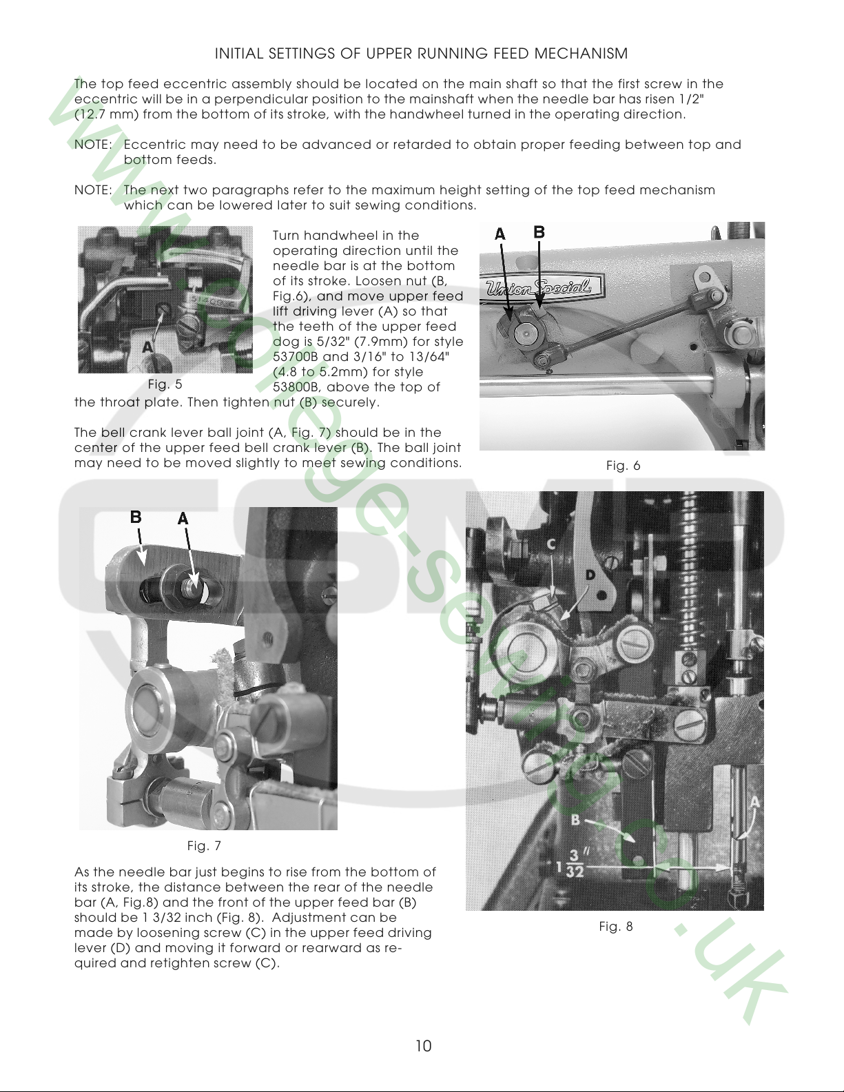
The top feed eccentric assembly should be located on the main shaft so that the first screw in the
eccentric will be in a perpendicular position to the mainshaft when the needle bar has risen 1/2"
(12.7 mm) from the bottom of its stroke, with the handwheel turned in the operating direction.
NOTE: Eccentric may need to be advanced or retarded to obtain proper feeding between top and
bottom feeds.
NOTE: The next two paragraphs refer to the maximum height setting of the top feed mechanism
which can be lowered later to suit sewing conditions.
Turn handwheel in the
operating direction until the
needle bar is at the bottom
of its stroke. Loosen nut (B,
Fig.6), and move upper feed
lift driving lever (A) so that
the teeth of the upper feed
dog is 5/32" (7.9mm) for style
53700B and 3/16" to 13/64"
Fig. 5
the throat plate. Then tighten nut (B) securely.
The bell crank lever ball joint (A, Fig. 7) should be in the
center of the upper feed bell crank lever (B). The ball joint
may need to be moved slightly to meet sewing conditions.
(4.8 to 5.2mm) for style
53800B, above the top of
Fig. 6
Fig. 7
As the needle bar just begins to rise from the bottom of
its stroke, the distance between the rear of the needle
bar (A, Fig.8) and the front of the upper feed bar (B)
should be 1 3/32 inch (Fig. 8). Adjustment can be
made by loosening screw (C) in the upper feed driving
lever (D) and moving it forward or rearward as re-
quired and retighten screw (C).
10
Fig. 8
INITIAL SETTINGS OF UPPER RUNNING FEED MECHANISM (CONTINUED)
Synchronizing the upper feed with the lower feed can be accomplished by loosening nut (A, Fig. 9) and
moving the ball stud in the upper feed driving shaft segment lever (B). Retighten nut.
CHANGING STITCH LENGTH
Fig. 9
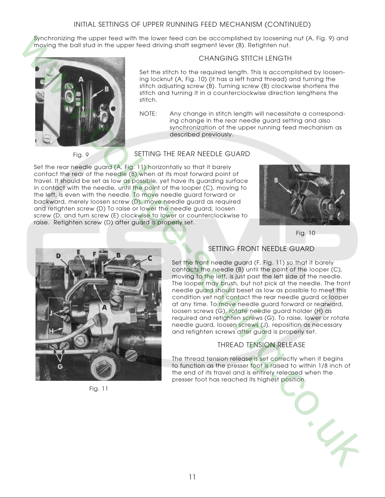
Set the rear needle guard (A, Fig. 11) horizontally so that it barely
contact the rear of the needle (B) when at its most forward point of
travel. It should be set as low as possible, yet have its guarding surface
in contact with the needle, until the point of the looper (C), moving to
the left, is even with the needle. To move needle guard forward or
backward, merely loosen screw (D), move needle guard as required
and retighten screw (D) To raise or lower the needle guard, loosen
screw (D; and turn screw (E) clockwise to lower or counterclockwise to
raise. Retighten screw (D) after guard is properly set.
Set the stitch to the required length. This is accomplished by loosen-
ing locknut (A, Fig. 10) (it has a left hand thread) and turning the
stitch adjusting screw (B). Turning screw (B) clockwise shortens the
stitch and turning it in a counterclockwise direction lengthens the
stitch.
NOTE: Any change in stitch length will necessitate a correspond-
ing change in the rear needle guard setting and also
synchronization of the upper running feed mechanism as
described previously.
SETTING THE REAR NEEDLE GUARD
Fig. 10
SETTING FRONT NEEDLE GUARD
Fig. 11
Set the front needle guard (F, Fig. 11) so that it barely
contacts the needle (B) until the point of the looper (C),
moving to the left, is just past the left side of the needle.
The looper may brush, but not pick at the needle. The front
needle guard should beset as low as possible to meet this
condition yet not contact the rear needle guard or looper
at any time. To move needle guard forward or rearward,
loosen screws (G), rotate needle guard holder (H) as
required and retighten screws (G). To raise, lower or rotate
needle guard, loosen screws (J), reposition as necessary
and retighten screws after guard is properly set.
THREAD TENSION RELEASE
The thread tension release is set correctly when it begins
to function as the presser foot is raised to within 1/8 inch of
the end of its travel and is entirely released when the
presser foot has reached its highest position.
11
THREAD TENSION RELEASE (CONTINUED)
If adjustmentis needed, loosen tension release lever screw (A, Fig. 12), located at the back of the
machine and move tension disc separator as required. Retighten screw. After adjustment there should
be no binding at any point.
The height of the presser bar (C, Fig. 3) is set correctly if it is possible to remove
the presser foot when the foot lifter lever (B, Fig. 12) is fully depressed.
If adjustment is necessary, turnhandwheel in operating direction until the needle
bar is in the low position. Loosen screws (G, Fig. 3), then, while holding presser foot
down on the throat plate surface, pry up presserbar connectionand guide(H) with
ascrewdriver to obtain the 1/16 inch setting and retighten screws.
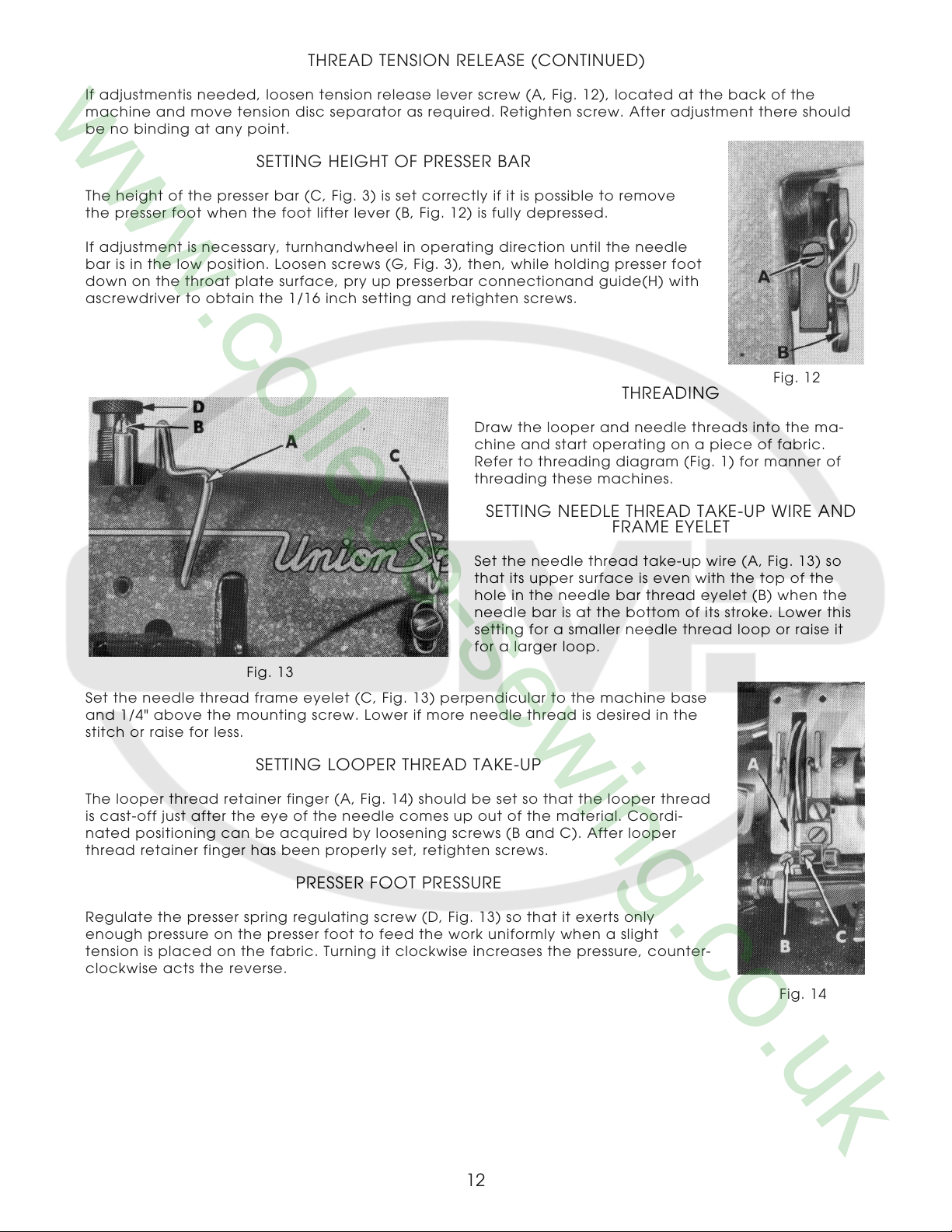
Set the needle thread frame eyelet (C, Fig. 13) perpendicular to the machine base
and 1/4" above the mounting screw. Lower if more needle thread is desired in the
stitch or raise for less.
SETTING HEIGHT OF PRESSER BAR
Fig. 12
THREADING
Draw the looper and needle threads into the ma-
chine and start operating on a piece of fabric.
Refer to threading diagram (Fig. 1) for manner of
threading these machines.
SETTING NEEDLE THREAD TAKE-UP WIRE AND
FRAME EYELET
Set the needle thread take-up wire (A, Fig. 13) so
that its upper surface is even with the top of the
hole in the needle bar thread eyelet (B) when the
needle bar is at the bottom of its stroke. Lower this
setting for a smaller needle thread loop or raise it
for a larger loop.
Fig. 13
SETTING LOOPER THREAD TAKE-UP
The looper thread retainer finger (A, Fig. 14) should be set so that the looper thread
is cast-off just after the eye of the needle comes up out of the material. Coordi-
nated positioning can be acquired by loosening screws (B and C). After looper
thread retainer finger has been properly set, retighten screws.
PRESSER FOOT PRESSURE
Regulate the presser spring regulating screw (D, Fig. 13) so that it exerts only
enough pressure on the presser foot to feed the work uniformly when a slight
tension is placed on the fabric. Turning it clockwise increases the pressure, counter-
clockwise acts the reverse.
12
Fig. 14
 Loading...