


iCOLOR 700
And
User Guide
EDGE2Print Software Installation Guide

Please ensure you foll ow ev ery step in order.
Overview of the Installation
System Requirements
- Optimal Requirement ( CPU, Memory, HHD and SO)
- Minimum Requirement for software WITHOUT variable data ( CPU, Memory, HHD and SO)
- Power 120v and 220v
- Network
o Processor: i7 3.5GHz 4770K or better
o Hard Drive: SSDs with 500MBs or greater
o Memory: 12 GB DDR3 1666MHz or greater.
o Motherboard: x79 Chip
o Windows 7 pro 64 bit only
o Processor: Intel i5
o Hard Drive: 7200 RPM
o Memory: 8 GB
o Windows 7 Pro 64 bit only
o Minimum outlet (5)
o (2) IP Addresses for the Feeder and Printer
o (3) Network Cables
Before starting the software installation, you need to ensure that you have
a clean version of Windows 7 with nothing installed. In order to do so, you
will need to make sure of the following:
□ There are no applications ins t a lled or currently running.
□ There are no antivirus programs installed.
□ The computer you’re planning to install the software on has the
printer and feeder on the same ne twork.
□ Ensure your user account has Admini s t rator privileges on the
local computer.
2

Contents
Contents ............................................................................................................................... 3
1. General Information ....................................................................................................... 5
Limitation of Liability ................................................................................................................................ 5
ICOLOR 700 Warranty ............................................................................................................................... 5
Safety Information .................................................................................................................................... 6
Specifications ............................................................................................................................................ 7
ICOLOR 700 Front View ............................................................................................................................. 7
ICOLOR 700 Rear View .............................................................................................................................. 8
ICOLOR 700 Internal Feeder View............................................................................................................. 9
ICOLOR 700 Rewinder View .................................................................................................................... 11
Feeder Display Menu Functions .............................................................................................................. 12
Printer Operator Panel ............................................................................................................................ 14
2. First Time Setup ............................................................................................................ 15
Unpacking and Setting Up the Printer .................................................................................................... 15
Change User Account Control Settings ................................................................................................... 18
Change Region ........................................................................................................................................ 20
Installing the EDGE2Print Software ........................................................................................................ 21
Setting up the IP Addresses .................................................................................................................... 30
Input IP Addresses into EDGE2Print........................................................................................................ 31
Selecting a Media ID ............................................................................................................................... 32
Setting up the Cost Calculator ................................................................................................................ 33
Changing Units of Measurement ............................................................................................................ 34
Changing the Color Registration ............................................................................................................. 35
Saving and Loading Page Information .................................................................................................... 37
3. Before Printing ............................................................................................................. 38
EDGE2Print User Interface ...................................................................................................................... 38
Measuring Your Media ............................................................................................................................ 39
Loading Media for Continuous Printing .................................................................................................. 41
Loading Media/Sensor Calibration for Die-cut Label Printing ................................................................ 46
3

How to Set Up the Rewinder .................................................................................................................. 48
4. Printing ........................................................................................................................ 51
Adding a Label Image .............................................................................................................................. 51
Selecting the Amount of Labels .............................................................................................................. 52
Adjusting the Print Alignment ................................................................................................................. 52
Printing .................................................................................................................................................... 54
5. Software Features & How To’s ...................................................................................... 55
How To Print a Full Bleed Die Cut Label .................................................................................................. 55
How to Create a New Media ID/Custom Media ID ................................................................................. 57
Editing a Newly Created Media ID .......................................................................................................... 59
Install Your Own ICC Profile .................................................................................................................... 60
Installing the Fonts in the RIP ................................................................................................................. 63
Nesting .................................................................................................................................................... 67
Rip Rotate Options .................................................................................................................................. 69
Rip Scaling Options ................................................................................................................................. 70
How to View Cost Report ........................................................................................................................ 71
How to Purchase Variable Data Software (iVDP) ....................................... Error! Bookmark not defined.
How to Install Variable Data Software (iVDP) ......................................................................................... 73
How to Print Using Banner Mode ........................................................................................................... 76
6. Trouble Shooting & Maintenance.................................................................................. 79
Toner Cartridge Replacement ................................................................................................................. 79
Image Drum Replacement ...................................................................................................................... 81
Replacing the Transfer Belt Unit ............................................................................................................. 83
Fuser Replacement ................................................................................................................................. 85
Clearing Paper Jams ................................................................................................................................ 86
Manual Sensor Calibration Using the Feeder (For Die Cut Labels Only)................................................. 90
How to Access the Settings as an Administrator .................................................................................... 94
Paper Sensor Error Codes ....................................................................................................................... 95
4

1. General Information
Limitation of Liability
Uninet’s total liability to the purchaser, or to any third party, for damages from any and all causes whatsoever,
regardless of the form of actio n, w hether in contract or in t ort, incl uding ne gligen ce, and any infringe ment of propriet ary
rights or any misappropriation or unlawful use of any proprietary rights or property of any third party shall, in the
aggregate, be limited to purchase price actually paid by the purchaser for the product relating to the damages. The
limitation of liability provisions of this agreement reflect an informed voluntary allocation of the risks (known and
unknown) that may ex ist in con nect ion w ith the provi sions of t he g oods a nd serv ices provi ded her eund er by Uninet and
that such voluntary risk allocation represents a fundamental part of the agreement reached between Uninet with the
purchaser.
Uninet shall not be li abl e f or a ny spec ial , direct or indirect, incidental, consequential, exemplar y , pu nitiv e or any s im ilar
or other damages of any nature suffered by the purchaser whatsoever including, without limitation, loss of use or lack
of availability of the purch aser facilities, i ncluding its co mputer resource s and any stored dat a, loss of prof its or revenue ,
or other commercial loss, or any claim for contribution or indemnity in respect of any claims against the purchaser,
regardless of whether Uninet has been advised of the possibility of such damag es.
ICOLOR 700 Warranty
Uninet (Uninet) warrants the ICOLOR 700 (Product) to be free from defects in materials and workmanship and will
remedy any such defect according to the terms of this Lim ite d Warra nty.
Uninet warrants the Product t o be free fro m defect s in mater ial and w orkm anship o ccurrin g under n ormal us age, w ithin
the normal operating range and duty cycles specified. If the Uninet Customer Service Representative Department
receives notice of su ch defe cts durin g the w arr anty perio d, Uninet at its option, an d w ithin a reaso nable ti me, w ill repa ir
or replace the defective Product. A certified Uninet service representative shall perform repairs, and such repairs, at
the option of Uninet, may be p erform ed at the custo mer site, a dealer site, a serv ice dep ot or the factory . Re place ment
Product, at the option of Uninet, may be either new or equiv alent in perfor mance to new. D elivery is defined by a signed
and dated receipt from the original carrier or Uninet dealer delivering the Product, or down time for repair and
replacement.
Uninet does not warrant the operation of the Product to be uninterrupted or error free. Uninet assumes no liability for
and holds itself harmless against any claims of consequential costs or damages which may arise from interruption or
error in the operation of the Product.
Uninet does not warrant defects, malfunctions and/or failures, which in its opinion, result from conditions of improper
use, abuse, neglect, operation outside the published environmental specifications, improper site preparation and
maintenance, the use of unqualified or unauthorized media (papers, films, toners, inks, fusers or belts), inadequate
preventative maintena nce, unaut horized modi ficati ons or un authoriz ed maintena nce. Su ch cond itions shal l render th is
warranty void and otherwise release Uninet from its liability under this Product warranty. Consumables are nonwarranty items.
All product returned to factory must be accompanied by an RMA number, obtained by calling the Uninet Service
Department at 403-204-5200 or as otherwise instructed. Shipping and handling charges to vendor for repair are the
sole responsibility of the customer. Uninet will cover shipping charges on the return of the repaired unit for the term of
the warranty as sta ted ab ov e. Shippi ng will consist of Standa r d Shi pm ent level or Best Effor t . Ac cel erated or Premium
Shipping Service is available but costs will be fully born by customer. Any international duties and taxes payable on
transporting the repaired unit across international borders will be the responsibility of the customer. The ICOLOR 700
Printer is a Canadian made product and therefore falls under the import/export laws of NAFTA.
A written receipt for the Product, showing the date of purchase, dealer’s name, and both the model and serial
number/PID’s of the Product must accompany any request or claim for work to be performed under this Limited
Warranty. Additional information on obtaining service under this Limited Warranty or for obtaining Extended Warranty
coverage contact Uninet directly at 866-415-Uninet (4797) or at 403-204-5200.
Uninet or its authorized service partner will repair, or at its option replace, at no charge, any defective
component(s) of the Product for a period of one (1) year from the date of purchase. This Limited Warranty
extends to the original purchaser only. This Limited Warranty does not extend to consumable items.
5

Safety Information
Your Uninet product has been carefully designed to give you years of safe, reliable performance. As with all electrical
equipment, there are a few basic precautions you should take to avoid hurting yourself or damaging the product.
Warning - Here are some of the things to look for:
• Save all provided documentation for future reference. Ensure all warning and instruction labels on the product are
read, understood and followed in order to prevent any risk of injury.
• This product may be heavy. Please check the weight of the product and take all necessary precautions to prevent
the risk of personal injury. Place your product on a firm, solid surface. If placed on something unsteady, it may fall
and be damaged. If placed on a soft surface, the vents may be blocked, causing the product to overheat.
• If the product is installed on a cabi net or h igh capa city fee der, ensure wheel locks are applied onc e pla ced in f ina l
position for use, to prevent risk of movement or injury.
• Protect your product fr om overheating. Make sure no obstr uct ions bl ock th e openi ngs of the produ ct. Do not pu t th e
product on or near a heat so ur ce (suc h as a radiator or heat regis ter). K eep t he prod uct out of direct sunli ght. Allow
enough room around the product for adequate ventilation and easy access to the paper paths. If the product is
placed in any kind of enclosure, make sure the enclosure is well ventilated to prevent a fire.
• When the product cover is open, do not touch the fus er u nit o r print head as you may receive burn s. Allow it to cool
before touching.
• If the product casing gets ex tremely h ot or s moke, u nusual smell s or ab nor mal noi ses ar e emitte d fr om the product ,
there is a risk of fire. Unplug the mains connector and contact Uninet service.
• Do not use the product near water. D o not spil l liquid of any kind on it. D o not con nect or disconnect t he pow er plu g
with a wet hand as this may cause electric shock. Unplug the product before you clean it. Use only a damp cloth;
do not use liquid or aerosol cleaners. Do not use an extremely flammable spray near the product as the product
contains high temperature parts that may cause a fire.
• Be certain that your power source matches the rating listed on the back of the product. If you are not sure, check
with your dealer or local power company before connecting the product.
• Do not connect this product to an uninterruptible power supply (UPS).
• Your product has a grounded, three-prong plug as a safety feature. This plug only fits into a grounded outlet. If the
plug does not fit, the outlet may be an older, non-gr ou nded ty pe. C ont act an electrician to have the o utle t r ep lac ed .
Do not use an adapter to defeat the grounding.
• Install the product near an easily accessible power outlet and avoid damaging the power cord. Do not put anything
on it or place it where it will be walked on. If the cord becomes damaged or frayed, replace it immediately.
• If you are using an extension cord or power bar with the product, make sure the total amperes required by all the
equipment on the extension is less than the extension’s rating. The total ratings of all equipment plugged into the
outlet should not exceed 15 amperes.
• Do not poke anything in the ventilation slots of the product. You could get an electrical shock or cause hazardous
electrical arcing, which could cause a fire.
• The acoustic noise of this product is less than 70 dB (A) as measured in accordance with EN ISO 7779.
• The operating condition range for your product is: 10 to 32°C and 20 to 80% RH. Operation of the product outside
this range could result in damage to the product.
• Do not throw toner cartridges or image drum cartridges into a fire as you may receive burns from a dust explosion.
• Ensure loose clothing and hair is kept clear of moving parts when the product is in operation to prevent possible
risk of injury.
• Ensure both the product and main s p ower switches are in the OFF po sit ion before connecting the AC power ca ble.
• Always hold the power plug to connect/ di sconne ct the pow er cabl e to/fr om the ma ins socket . Unplug ging by pulling
on the cable can cause fraying and may lead to fire or electric shock.
• Use only the power cable supplied. Using a power cable not intended for this product may lead to fire or electric
shock. Do not use the power cable supplied with this product for any other electri cal equ ip ment.
• Aside from the routine maintenance described in the documentation, do not try to service the product yourself.
Removing the cover may expose you to shocks or other hazards.
• Do not make any adjustments other than those outlined in the documentation. You may cause damage that will
require extensive repair work. The provided documentation explains how to get your product serviced by qualified
Uninet technicians. If anything happens that indicating your product is not working properly or has been damaged,
unplug it immediately and follow the procedures in the provided documentation for having your product serviced.
6

Specifications
Print Speed
Up to 9.14 meters/min (30 ft/min)
Technology
Single Pass 4 Color LED (CMYK)
Printer Processor1
533 MHz
Media Width
Minimum: 6.0 inches (152.4 mm)
Maximum: 8.5 inches (216 mm)
Print Width
Minimum: 6.0 inches (152.4 mm)
Maximum: 8.24 inches (209.3 mm)
Print Length
Up to 420 meters (1378 ft)
Substrate Types2
Die Cut Label Stock
Tag Stock
Print Quality
1200 x 600 dpi
Toner Supplies3
CMY - 11,500 pages @ 5%
(Rated according to ISO/IEC 19798 guidelines)
Drum Supplies4
CMYK - 30,000 pages @ 5%
(Rated according to ISO/IEC 19798 guidelines)
Feeder System
Input roll maximum outside diameter: 8 inches (203 mm)
Auto adjusting form synchronization
Rewinder System
Output roll maximum diameter: 8 inches (203 mm)
Maximum output roll weight: 14 lbs (6.35 kg)
Dimensions (H X W X D)
Printer & Feeder: 26" x 17.1 "x 21.5" (660 mm x 434 mm x
Rewinder: 16" x 19.75" x 19" (406 mm x 502 mm x 483 mm)
Weight
Printer & Feeder: 110 lbs (49.9 kg)
Rewinder: 27.65 lbs (12.54 kg)
Operating Environment
Temperature: 10°C to 20°C (50 to 89.6°F)
Humidity: 20 to 60% RH
Power
110 - 127 VAC, 50/60 Hz @ 1150W
220 - 240 VAC, 50/60 Hz @ 1150W
Certifications
FCC Class A, CE, cTUVus, CCC
Warranty
1 year – Parts & Labour
1. Published performance results based on laboratory testing. Individual results may vary.
respective manufacturers. ©2014 Copyright, Uninet. All Rights Reserved. All content is subject to change without notice.
ICOLOR 700: System Specifi cat io ns
Kiss Cut Label Stock
Non Die Cut Label Stock
K - 11,000 pages @ 5%
Core inside diameter: 3 inches (76.2 mm)
Maximum input roll weight: 14 lbs (6.35 kg)
Cut on the fly, auto cut
Auto page width registration
Front Panel LCD interface
Web management system torque
Core inside diameter: 3.0 inches (76.2 mm)
546 mm)
2. This product is designed and engineered to operate only with genuine Uninet consumables and certified media
substrates. Please contact Uninet for the most current Certified Media List of substrates available.
3. Letter-size sheets at 5% coverage. Printer ships with a 7,500 page set of starter toners.
4. Based on 500 cut-sheet pages/job.
Uninet reserves the right to change product specifications without notice. Trademarks are the property of their
ICOLOR 700 Front View
7

1. LED Heads
2. Toner Cartridges (C, M, Y, K)
3. Front Cover Release Lever (Blue Handle
Behind Cover)
4. Cut On The Fly Module
5. Feeder Display Menu
6. Spindle Pin
7. Left and Right Media Guides
8. Static Bar
9. Front Cover
10. Black Tray Latches
11. Width Adjustment Wheel
12. Extension Arms
13. Feeder
14. Top Cover Release Button
15. Drum Units (C, M, Y, K)
16. Rewinder
17. Fuser Release Levers
ICOLOR 700 Rear View
8

Note: USB port is not available
ICOLOR 700 Internal Feeder View
1. Printer Network Connection
2. Printer Power Outlet
3. Feeder Network Connection
4. Feeder Power Outlet
5. Paper Exit Path
6. Rewinder Plate (Rewinder Not Shown
Attached)
9

1. Drive Roller
2. Left and Right Media Guides
3. Tension Roller
4. Pinch Roller
5. Static Bar
6. Black Tray Latches
7. Width Adjustment Wheel
8. Extension Arms
9. Spindle Pin
10

ICOLOR 700 Rewinder View
1. Left End Disk
2. Switch Panel
3. DC Power In
4. Spindle
5. Core Adjustment Knob
6. Right End Disk
7. Dancer Arm
8. Lockdown Knob
9. Width Adjustment
11

Feeder Display Menu Functions
feeder back online.
This item configures the parameters for the top load sensor. To access the I2: Top Load Sensor menu,
feeder back online.
3
4
5
1. Display – Displays the feeder status and any error messages
2. On Line/UP – Toggles between Online and Offline, and also serv es as an “UP” sele cti on bu tton
3. DOWN – Serves as an “DOWN” selection button
4. Load Button – Press to complete loading paper
5. Menu/Select - Accesses the three menus: Feeder Configuration, Feeder Calibration and Network Settings
To access the feeder menu items, press the On Line button to toggle online or offline and gain access to your Menu
system. There are three main menu items: Feeder Configurations, Feeder Calibrations and Network Settings.
M1: Feeder Configurations – NOT AVAILABLE
To access the feeder configuration menu, select On Line to turn the feeder offline. Press the Menu key once for
the M1: Feeder Config menu to appear. The following item is under Feeder Config:
To access the I1: Media Type menu, select the On Line button to take the feeder offline.
I1:
Media
Type
To change the media type, hold down the Menu key until the * disappears. Use the UP and DOWN
arrow keys to select the required media. To save the selection, hold down the Menu key again until
the * appears. The media type is now set. To exit press the Menu button. Select On Line button to
take the feeder back online.
M2: Calibrations
Under the Calibrations menu items, it is possible to configure both the Top and Bottom Load Sensors, the Sensor
Gap, Cut on the Fly parameters and Auto Calibration menus.
To access the M2: Calibrations menu, select On Line to turn the feeder offline. Press the Menu key twice for the M2:
Calibrations menu to appear. The following ite ms are under Calibrations:
This item configures the parameters for the bottom load sensor. To access the I1: Bot Load Sensor
menu, select the UP arrow until I1: Bot Load Sensor is shown on the display.
I1: Bot
Load
Sensor
I2: Top
Load
Sensor
To change the settings, hold down the Menu key for about one full second until the * disappears. Use
the UP and DOWN arrow keys to set the required values. To save the values, press Menu. When all
values have been set, press and hold the Menu key for about one full second, until the * appears. The
bottom load sensor values are now set. To exit press the Menu button. Select On Line button to take the
select the UP arrow until I2: Top Load Sensor is shown on the display.
To change the settings, hold down the Menu key for about one full second until the * disappears. Use
the UP and DOWN arrow keys to set the required values. To save the values, press Menu. When all
values have been set, press and hold the Menu key for about one full second, until the * appears. The
top load sensor values are now set. To exit press the Menu button. Select On Line button to take the
12

This item configures the gap between back sensors. To access the I3: Reg Sensor Back menu, select the
UP arrow until I3: Reg Sensor Back is shown on the display.
feeder back online.
I4:
The Network Settings menu items allow configuration of the IP Address, the Subnet Mask and the Default
times for the M3: Network Settings menu to appear. The following items are under Network Settings:
This item sets the IP Address. To access the I1: IP Address menu, select the UP arrow until I1: IP
online.
I3: Reg
Sensor
Back
RSEN
Autocal
COTF
Paramet
M3: Network Settings
To change the settings, hold down the Menu key for about one full second until the * disappears. Use
the UP and DOWN arrow keys to set the required values. To save the values, press Menu. When all
values have been set, press and hold the Menu key for about one full second, until the * appears. The
back sensor or gap values are now set. To exit press the Menu button. Select On Line button to take the
This item configures the auto calibration values. To access the I4: RSEN Autocal menu, select the UP
arrow until I4: RSEN Autocal is shown on the display.
To change the settings, hold down the Menu key for about one full second until the * disappears. Use
the UP and DOWN arrow keys to set the required values. To save the values, press Menu. When all
values have been set, press and hold the Menu key for about one full second, until the * appears. The
autocalibration values are now set. To exit press the Menu button. Select On Line button to take the
feeder back online.
This item configures the parameters for Cut on the Fly. To access the I5: COTF Parameters menu, select
the UP arrow until I5: COTF Parameters is shown on the display.
I5:
To change the settings, hold down the Menu key for about one full second until the * disappears. Use
the UP and DOWN arrow keys to set the required values. To save the values, press Menu. When all
ers
values have been set, press and hold the Menu key for about one full second, until the * appears. The
COTF parameter values are now set. To exit press the Menu button. Select On Line button to take the
feeder back online.
Gateway.
To access the M3: Network Settings menu, select On Line to turn the feeder offline. Press the Menu key three
Address is shown on the display.
I1: IP
Address
Subnet
Mask
Gateway
To change the settings, hold down the Menu key for about one full second until the * disappears. Use
the UP and DOWN arrow keys to set the required values. To save the values, press Menu. When all
values have been set, press and hold the Menu key for about one full second, until the * appears. The
IP Address now set. To exit press the Menu button. Select On Line button to take the feeder back
This item sets the Subnet Mask. To access the I2: Subnet Mask menu, select the UP arrow until I2:
Subnet Mask is shown on the display.
I2:
To change the settings, hold down the Menu key for about one full second until the * disappears. Use
the UP and DOWN arrow keys to set the required values. To save the values, press Menu. When all
values have been set, press and hold the Menu key for about one full second, until the * appears. The
Subnet Mask is now set. To exit press the Menu button. Select On Line button to take the feeder back
online.
This item sets the Default Gateway. To access the I3: Gateway menu, select the UP arrow until I3:
Gateway is shown on the display.
I3:
To change the settings, hold down the Menu key for about one full second until the * disappears. Use
the UP and DOWN arrow keys to set the required values. To save the values, press Menu. When all
values have been set, press and hold the Menu key for about one full second, until the * appears. The
default Gateway now set. To exit press the Menu button. Select On Line button to take the feeder
back online.
13

Printer Operator Panel
ON: A warning occurs. Printing
OFF: Normal Condition
Enters the Menu mode. In Menu
jump from top to bottom
ON: Ready to receive data
1.Ready LED
2. Display
3. Menu Scroll
Buttons
4. On Line
Button
5. Help Button
BLINKING: Processing data
OFF: Offline
Displays the printer status and any
error messages.
mode, forwards or reverses the
menu item displayed.
Press for 2 seconds or longer to
Switches between ONLINE and
OFFLINE
Scrolls the HELP screen
Provides advice when an error
occurs
6. Attention LED
7. Back Button
8. Enter Button
9. Cancel Button
10.Power Save/
Wake up Button
may be possible (e.g. low toner)
BLINKING: An error occurs.
Printing not possible (e.g. toner
empty)
Returns to the previous menu
In the ONLINE or OFFLINE mode:
enters the Menu mode.
In the Menu mode: determines the
setting selected.
Deletes the data being printed or
received when pressed for two
seconds or longer.
Exits the menu and goes ONLINE
when pressed in the Menu mode.
Pressing this button switches the
machine into sleep or wake- up
mode.
14
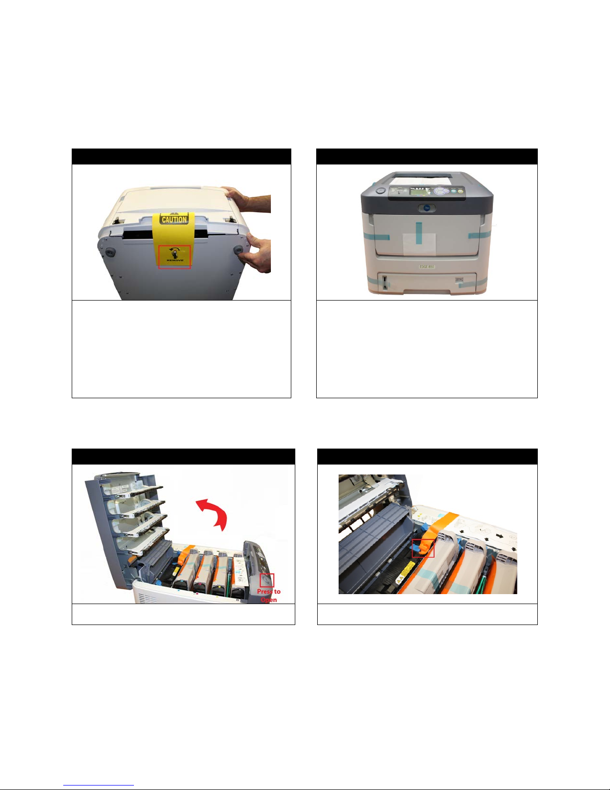
2. First Time Setup
With two people lift the top (feeder) box off of the
door.
Unpacking and Setting Up the Printer
STEP 1 of 10 STEP 2 of 10
bottom (printer) box. Open the feeder box and
remove the feeder.
Remove the wing nut on the bottom of the feeder
before placing upright on any surface. Position the
feeder on a level surface. Open the feeder and
remove all packaging material. Close the feeder
Lift the lid off of the printer box. With two people,
remove the printer from the box. Remove all of the
packaging tape from the outside of the printer.
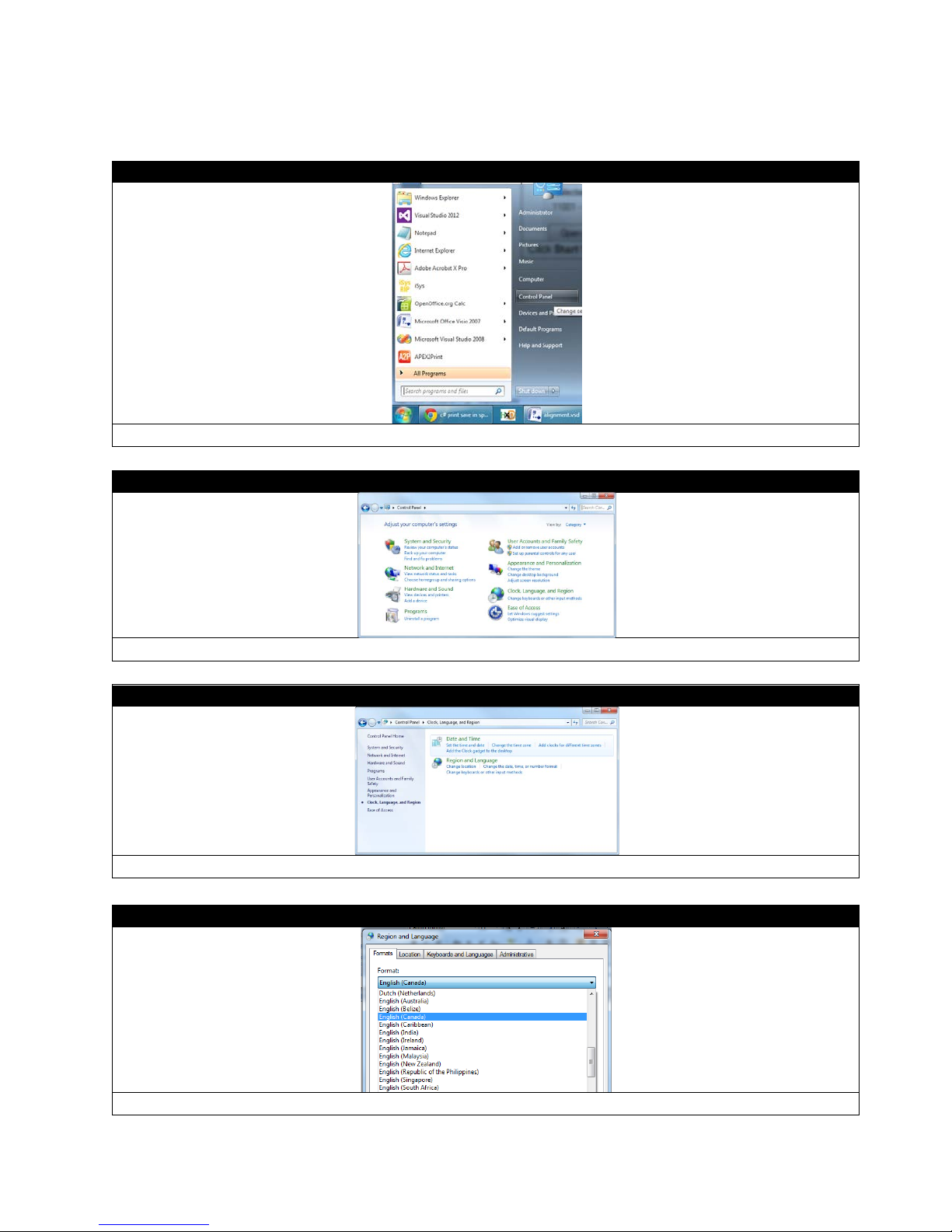
STEP 3 of 10 STEP 4 of 10
Press the button to open the top lid. Remove the fuser shipping lock.
15

STEP 5 of 10 STEP 6 of 10
Pull the drums/toners out of the printer. Remove
all consumables
Unpack the rewinder, removing all of the
install on the printer.
Attach the rewinder plate to the feeder using the
moving it slightly left or right. Adjust accordingly.
the protective film. Place the drums and toners
back into the printer. Ensure all four toners are
locked into the four drums by checking the blue
lever. Close the printer lid.
IMPORTANT: Once the drums/toners are
removed, they must not be exposed to light for
more than 5 minutes. To prevent damage, cover
them with a dark sheet or reinstall.
NOTE: All consumables are print ready and do not
need to be replaced upon opening. Once the
consumables have reached their lifespan, please
refer to the appendix on how to replace and install
Align the printer with the pins located on the top of the
feeder. Keep the printer level and flush to the front
while lowering it onto the feeder.
STEP 7 of 10 STEP 8 of 10
packaging tape.
Unwrap the rewinder attachment and prepare to
screws located on the back of the feeder. Make sure it
is in line with the paper output feeder. You can adjust
the rewinder plate once it is loosely secured by
16

Step 9 of 10
Attach the rewinder mechanism to the plate using the black thumb screws. Make sure that the rewinder
The rewinder attachment has been successfully installed.
Once the rewinder is installed, you need to connect the network and power cables to the correct outlets.
All of the outlets are located on the back side of the ICOLOR 700, con nec t accor dingly.
mechanism is fully supported so it does not bend or break the rewinder plate.
STEP 10 of 10
17

Change User Account Control Settings
STEP 1 of 5
Start
Control Panel
STEP 2 of 5
Click
from Windows toolbar, and then click
Click User Account and Family Safety.
.
18

STEP 3 of 5
Click User Accounts.
STEP 4 of 5
STEP 5 of 5
Click Change User Account Control settings.
Move the left bar all the way down to the bottom and click OK.
19
Change Region
STEP 1 of 4
STEP 2 of 4
Clock, Language, and Region
STEP 3 of 4
STEP 4 of 4
Click Start from Windows toolbar then click Control Panel.
Click
Click Region and Language.
.
From the Format list, select English (Canada) and then click OK.
20

Installing the EDGE2Print Software
Installing the RIP - STEP 1 of 18
Uninet utilizes Dropbox for sending the software files. Please send Uninet an email for sharing folders. After this
in the required information and select Sign Up again to register. If it is not your first time using Dropbox, log in.
Installing the RIP - STEP 2 of 18
email confirmation, Uninet will share the software files to your email address. To begin the installation you will
need to log on to the internet and go to
www.dropbox.com. Click Sign Up if it is your first time using Dropbox. Fill
Select one option according to your requirement.
21

Installing the RIP - STEP 3 of 18
Click Sharing on the left side. For example, you have 1 new sharing from Uninet, 1 new shared folder
Installing the RIP - STEP 4 of 18
invitations will show in the middle of the webpage. Click that link.
The window above will pop up. Please click Verify it now, then cl ick Send email to verify your email address.
22

Installing the RIP - STEP 5 of 18
Installing the RIP - STEP 6 of 18
Then click on the EDGE2Print folder from the list. If you cannot see this list, please contact our customer service to
Click Verify your email from your email, then you will see the pop-up window above. Click Accept.
get the sharing capabilities.
23

Installing the RIP - STEP 7 of 18
Installing the RIP - STEP 8 of 18
Click 1st Re-Install RIP.zip fr om the list and cl ic k Download to save your file.
Unzip and open the folder you just downloaded, click Prepare_iSys_RIP_v2.4.exe to install.
24

Installing the RIP - STEP 9 of 18
The KEYLOK and Sentinel Drivers will start to install automatically. Wait until the Install Dongles then Click to
Continue button becomes available before proceeding to the next step.
Installing the RIP - STEP 10 of 18
Insert the two dongles and then click Install Dongles then Click to Continue.
25

Installing the RIP - STEP 11 of 18
The screen above will pop up.
Installing the RIP - STEP 12 of 18
Wait until the window disappears and the window above shows like this. Click Done. The RIP is now installed.
26

Installing the EDGE2Print Software - STEP 13 of 18
Return to the Dropbox folder. Click EDGE2Print Installation from the list.
Installing the EDGE2Print Software - STEP 14 of 18
Select EDGE2Print_Install.msi, and click Download to save your file.
27

Installing the EDGE2Print Software - STEP 15 of 18
Installing the EDGE2Print Software - STEP 16 of 18
Click on the file you just downloaded to install.
The window above will be shown. Click Next to continue.
28

Installing the EDGE2Print Software - STEP 17 of 18
Click Next to continue.
Installing the EDGE2Print Software - STEP 18 of 18
Wait until the process is finished, then c lick Close. Your software is now fully installed.
29

Setting up the IP Addresses
*For any inquiries regarding setting the IP address please contact your support team
*For any inquiries regarding setting the IP address please contact your support team
In order to connect to the ICOLOR 700, you need two predetermined static IP Addresses and two network
cables, one for the printer and one for the feeder.
STEP 1 of 2: Setting the IP Address on the Printer
1. Select Menu>Using DOWN arrow, scroll to Admin Setup> Select Enter
2. At the “Enter Password” prompt, enter the 6 digit Admin password by using the UP arrow, then Enter. The
default password is: aaaaaa(6 x a). Select Enter.
3. Select Network Setup
4. Hit the DOWN key until you can select IPv4 Address Set then Enter. Use the UP/DOWN arrow keys to set
the value you need. Press Enter to move across the address. Press Back to Network Setup.
5. Hit the DOWN arrow key until you can select Subnet Mask. Use the UP/DOWN arrow keys to set the value
you need. Press Enter to move across the address. Press Back to Network Setup. (The default subnet
mask is 255.255.255.0. If that needs to be changed, follow the same procedure as for the IP Address.)
6. Press Back until you have exited the menu
7. Write this IP address down as you will need to input it into the software
STEP 2 of 2: Setting the IP Address on the Feeder
The Network Settings menu items allow configuration of the IP Address, the Subnet Mas k and the Default
Gateway.
1. Press Online to turn the feeder Offline.
2. Press the Menu button three times until M3: Network Settings is shown
3. Press the UP arrow key to I1: IP Address
4. Hold down the Menu key until the * disappears (about 1 full second). Use the UP and DOWN arrow keys to
set the required values.
5. When the address is set, hold down the Menu key again for about 1 full second, until the * reappears. The IP
address is now set/saved.
6. Press the UP arrow key again to set the subnet mask. The default subnet mask is 255.255.255.0. If that
needs to be changed, follow the same procedure as for the IP Address.
7. Select the UP arrow key again to get to I3: Gateway. Use the same procedure to set the Gateway as used to
set the IP Address.
8. Write this IP address down as you will need to input it into the software.
30

Input IP Addresses into EDGE2Print
STEP 1 of 2
Launch the software. T he f ol lo wing window will pop up auto mati cal ly . I np ut t he proper IP address for the printer and
feeder, then click Save.
STEP 2 of 2
If you need to change the IP address, you can click Setup OptionsPrinterIP Address from the toolbar.
31

Selecting a Media ID
STEP 1 of 2
STEP 2 of 2
The following media list will open. This list contains medias that have been certified by Uninet. You can select one
from the list (by double click).
Open the EDGE2Print software, click Media from the toolbar.
32

Setting up the Cost Calculator
STEP 1 of 2
STEP 2 of 2
In the following window, input the price paid for each consumable. This will calculate the cost per label. This value will
appear in the Image List.
Click Setup OptionsSoftwareCost Calculator from the toolbar.
33
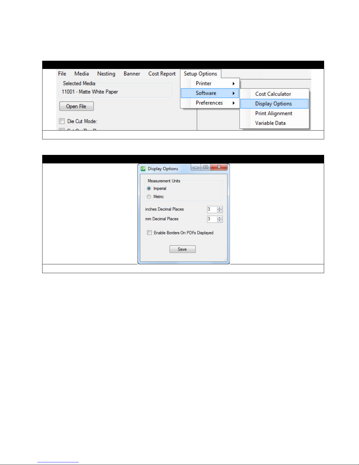
Changing Units of Measurement
STEP 1 of 2
STEP 2 of 2
Save.
Select Setup OptionsSoftwareDisplay Options from the toolbar.
Select your preferred measurement units to display and click
34

Changing the Color Registration
STEP 1 of 4
Select Setup OptionsPrinterColor Registratio n from the toolbar.
selected in the softw are libr ary. Y ou will want to ensure that yo ur front p anel setti ngs and softw are settings ar e the s ame
the exact results that are to be expected. If you do not have an exact match with the front panel and
media library settings, there is potential for an error on the front panel.
STEP 2 of 4
Print Registration Plot.
Go to the front panel of the printer and select the Media Type and Media Weight, based on the media settings you
so you receive
Click
35

STEP 3 of 4
The printer will print a similar page that will aid in determining the proper registration values across CMY.
C:6 M:4 Y:0; this is because the pixels are perfectly filled within the boxes.
STEP 4 of 4
With the values determined i n the previou s step, the f ollowing adjustment s can be made t o the Color Reg istratio n Form.
Note: If there are troubles with the color density, select Printer Density Adjust Before Every Job.
IMPORTANT: Use the third page printed to determine the values.
Using a printer's loupe or best judgment, determine the best values. In this case, the correct values are as follows:
Click Apply to set.
36

Saving and Loading Page Information
STEP 1 of 2
STEP 2 of 2
To load the saved page information, click FileLoad Page Information. Select the page information file you saved
before, and then click Open.
Click FileSave Page Information from the toolbar. The current page information in the software will be saved.
37

3. Before Printing
STEP 1
EDGE2Print User Interface
The following shows the interface of the EDGE2Print software.
38

Measuring Your Media
Gutter: Measures the distance between labels
by using the horizontal gap
Alley: Measures the distance between labels
by using the vertical gap
Measure Width of Paper, Horizontal and Vertical Gaps between labels (if applicable), and input these values into
EDGE2Print. Input the values into Page Information in the EDGE2Print Software.
STEP 1 of 4 STEP 2 of 4
Measure the total width of paper. Input the value
into Media Width.
Measure the distance of horizontal gap. Input the
value into Gutter.
STEP 3 of 4 STEP 4 of 4
Measure the distance of vertical gap. Put the value
into Alley.
You also should measure the width and height of
the label. Save the values for later.
39

Measuring Tip
way! Measure as least one meter of the media, and
measure the height of one label. Then calculate the distance of the gap. The longer you measure the media, the more
precise value you will get.
Ex. For the left picture, we measure 9 label lengths plus 9 gutter lengths; the total length is 1171.58 mm (46.125
In order to get more precise value of Gutter, there is a better
inches).
Then measure one label length, which is 127mm (5 inches).
Therefore, the gutter value should be (1171.58/9)-127= 3.177 mm
40

Loading Media for Continuous Printing
STEP 1 of 11
IMPORTANT: Only use with Media with a width ranging from 6” to 8.5” wide
Note: Maximum Printable Width is 8.24”
Make sure the sides of the roll are straight and flush with the core.
STEP 2 of 11 STEP 3 of 11
41

STEP 4 of 11
STEP 5 of 11
Open the feeder tray by pushing the black tray
latches inward and pulling the tray outwards.
Pu ll out the feeder tray and open the front tray.
Cut a small piece of the media and to use to adjust the width of the guides.
Open the left and right media guides.
Place the paper between the left and right media guides.
Use the rewinder to adjust the width, making sure there is no space on both sides and the paper can pass through
with no tension.
42

Remove the plastic spindle and insert it into the core of the media roll, ensuring that you keep the edges of the roll
completely flush with the core.
STEP 6 of 11
Feed the media through, ensuring it is between the tension and pinch rollers.
STEP 7 of 11
Place the roll in the feeder between the extension arms, with the leading edge of the material at the bottom of the tray.
Adjust the width of the extension arms to fit the paper roll’s width, if necessary.
43

Power on the printer. When the feeder displays
leaving a clean leading edge for printing.
With the media flush against the back plate in the feeder, ensure that there is no extra space on each side of the
media and the left/right med ia guide s.
Feed the media underneath the drive roller and ensure that the paper is at the same level as the top of the rollers.
Back wind the roll if necessary.
Close the red left/right media guides. Ensure that the media is not buckling or too snug against the guides before
proceeding to the next step.
STEP 8 of 11 STEP 9 of 11
Close the front tray cover and push the tray in.
Note: DO NOT press the Load butto n at this
stage.
“Status: Require Load,” press the Load button on
the feeder.
The media will be fed upwards and cut the substrate,
44
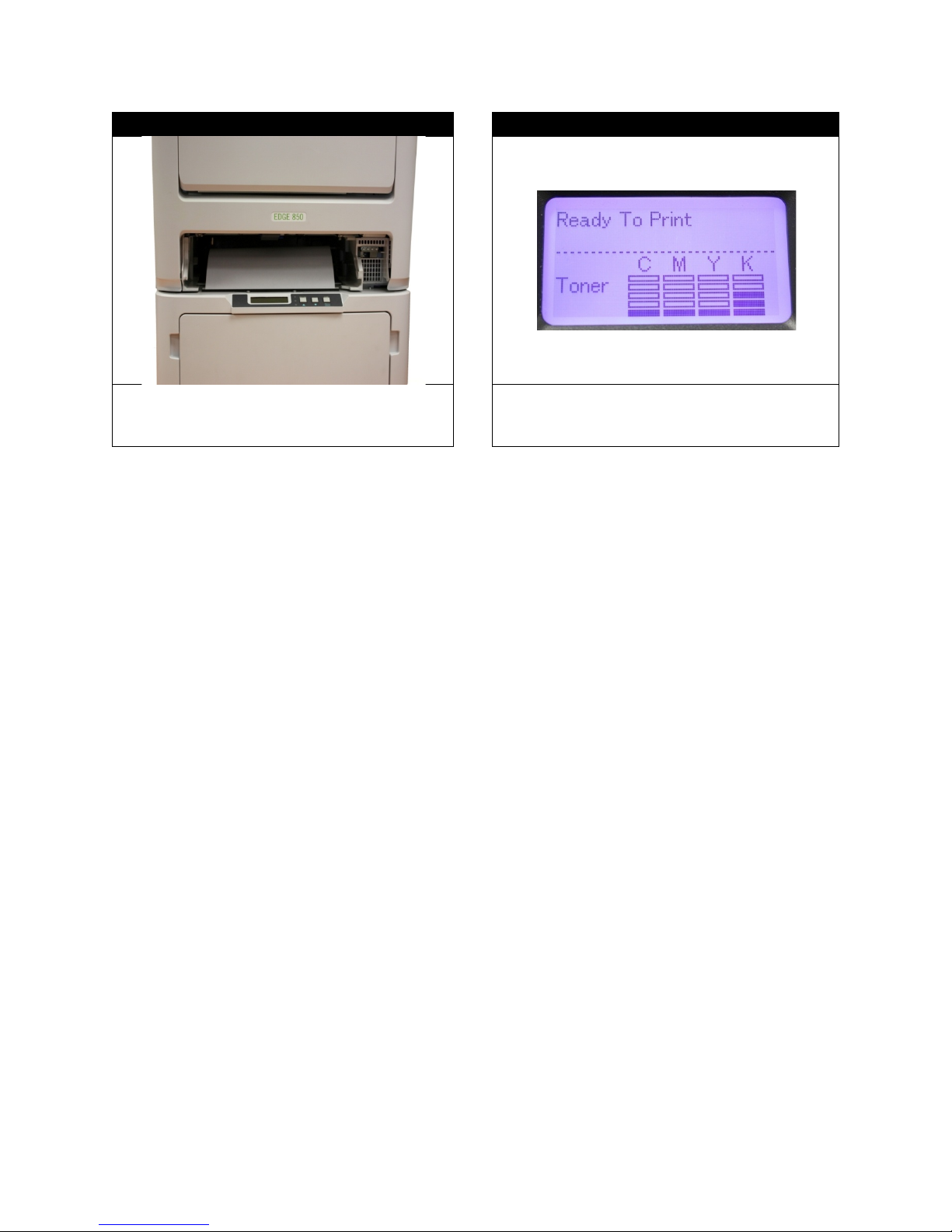
STEP 10 of 11 STEP 11 of 11
After the feeder cuts the paper, remove the Cut on
the Fly module and scrap material. Put the Cut on
the Fly Module back in its position.
The CMYK colors will adjust, and the printer will
display “Ready To Print” when it is ready.
45

Loading Media/Sensor Calibration for Die-cut Label Printing
STEP 1 of 4
STEP 2 of 4
Refer to steps 1-8 of “Loading Media for Continuous Printing” for how to load the roll of media. After the die cut
Close the front tray cover and push the tray in.
Launch the EDGE2Print software. If your media is die cut, select Die Cut Mode. Then select the Sensor Type. (We
will use the Gap Sensor as the example in the following instructions.)
Note: If the Calibrate button is red, it means the sensor needs calibration before printing.
roll is loaded into the tray, line up the gap of the labels about one inch below the sensor.
Close the left/right media guides. Backwind the roll to ensure there is no tension when the sensor is calibrating. If the
roll is fully wound and has tension on it, it will skew the calibration.
46

STEP 3 of 4
After the media is properly loaded, click Calibrate in the software. The following dialogue will pop up. Select Run
Calibration. The printer will run the paper upwards about 6 inches to the nearest gap mark.
Copy Media Library Settings To Media Library
STEP 4 of 4
If the calibration did not work, an error screen will pop up and you will have to adjust the roll before performing another
You are now ready to add a label image and print a die-cut label.
Note:
1) You can use previously stored values in the feeder from the last use by clicking Copy Feeder Settings To
Media Library.
2) You can also manually input the values for Sensor Gain and Sensor Window under the Media Library Settings,
and then click
calibration.
After calibration is done. Turn the feeder Offline and hold the DOWN arrow on the feeder display to cut extra paper.
Remove the excess paper, then turn the feeder On Line and press Load to finish the loadin g pro cess.
to update the values in the feeder.
47

How to Set Up the Rewinder
STEP 1 of 6
Loosen the Core Adjustment Knob. Place a core on the Rewinder Spindle. Make sure the core is the same width of
flush against the left end disk. If the core is slightly smaller, place it in the center using your best judgme nt.
STEP 2 of 6
Cut a section of the media you’ll be using to print. Place that piece of media flush against the Left End Disk and
core, it will cause the roll to wind haphazardly, not wind tightly and create bubbles in the roll.
the media you’re printing on or slightly smaller. If the core is the exact same width as the media, ensure it is placed
adjust the Right End Disk to fit the media. Ensure that the paper is flat against the core and there is no excess space
on each side of the End Dis k s. Tighten the Core Adjustment Knob.
NOTE: If there is excess space between the core and the Left/Right End Disks OR the media is not flat against the
48

STEP 3 of 6
Loosen the Lockdown Knob for positioning. When you are ready to print, send a small section of labels to the printer.
While the section is printing, adjust the rewinder left/right using the Width Adjustment Knob, aligning the rewinder
Lockdown Knob.
STEP 4 of 6
Plug the DC Power In, and then plug the end of the power cord into a socket. Turn the rewinder on by turning the
switch to REV.
with the paper path as the labels exit the machine. Once the paper path and rewinder are aligned, tighten the
49

STEP 5 of 6
Press Print in the software when your job is ready. As the paper exits the printer, lift the Dancer Arm and bring the
media underneath the Dancer Arm and up onto the core. Secure it to the core using a section of media or excess
or create bubbles between the reams.
STEP 6 of 6
When the roll is done, turn off the rewinder. Unscrew the Core Adjustment Knob on the Spindle. Remove the roll
from the Spindle and return the Right End Disk to its initial position.
label.
Lower the Dancer Arm downwards to begin winding the material onto the core. Place your hand gently on top of the
core to create some initial tension at the beginning of the roll. Once the media is winding, release the Dancer Arm
gently downwards onto the paper. The roll will continue to wind.
NOTE: Winding speed is determined by the position of the Dancer Arm. Lowering the arm will speed up the winding
and lifting upwards will slow it down.
NOTE: If the roll seems to be winding too loosely, place your hand on the top of the roll while it’s winding. This will
increase the tension momentarily. Be careful when doing this as too much tension will cause the roll to wind unevenly
50

4. Printing
STEP 1 of 3
The EDGE2Print uses PDF files only. To open a file, choose FileOpen, click O pe n F i le button to select your PDF
file, or you can simply drag and drop your PDF file to the Preview Screen.
STEP 2 of 3
You can load multiple PDF files as long as they have the same dimensions, but the number of PDF files shouldn't
aligned in columns.
STEP 3 of 3
Image List
Adding a Label Image
exceed the column numbers on the die cut media. The images will show in the Preview Screen, and multiple files are
The information of the images will show in the
on the left.
51

Selecting the Amount of Labels
STEP 1 of 1
Enter how many labels you want to be printed and press Add. The EDGE2Print software will automatically round the
amount of labels up to complete a full row. Then click Print to start printing labels.
STEP 1 of 3
Note: For the first print, you need to adjust vertically where the printer starts printing the label images.
more than 20 inches of labels for the first print. Make sure the proper values for paper width, gutter and alley
set to 0 without affecting the color registration.
Adjusting the Print Alignment
Select Setup OptionsSoftwarePrint Alignment from the toolbar. Set the proper Pattern Header Length. Print
measurements are inserted into the EDGE2Print software.
Recommendation: The header NEEDS to be 22 inche s l on g in or d er t o ad ju st t he color registration. T he f oot er c an be
52

STEP 2 of 3
Check the start position. The 2 0 inches of header colo r patter ns are used f or calibrat ion. The gap betw een labels should
gap on the label line. If the labels are not aligned after the third copy, adjust the start position value
according to how far the label is from the gap.
STEP 3 of 3
be in line with the
Start Position
Positive Value (+): Move print down
Negative Value (-): Move print up
53
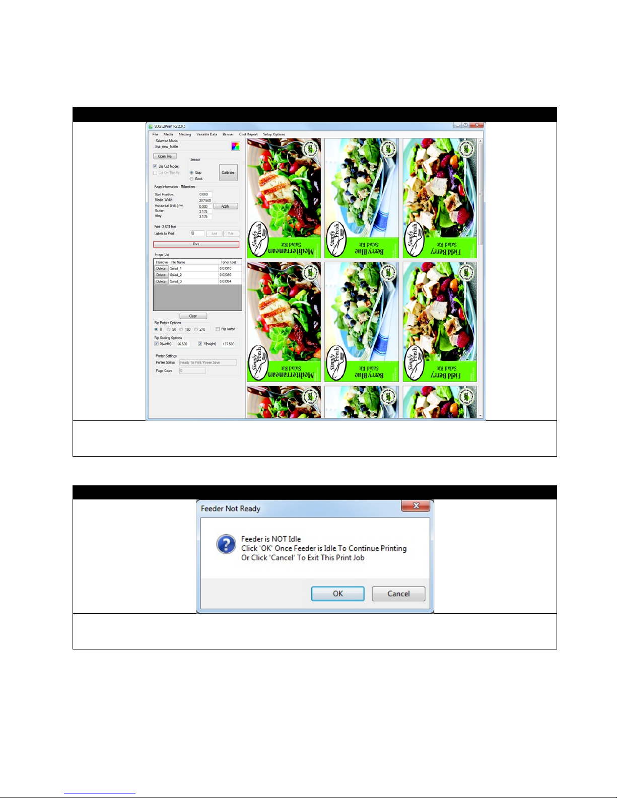
Printing
STEP 1 of 2
STEP 2 of 2
Once all PDF files have been added a nd the Page Information adjustments have been made, click Print button to st ar t
printing.
If Done is not selected on the feeder unit, the printer will remain in a busy state and display a Feeder Not Ready
window. Press Done on the feeder unit and click OK.
54

5. Software Features & How To’s
How To Print a Full Bleed Die Cut Label
The following is a detailed guide to create an oversized label image on top of a die cut label. The term over bleed
means that there is a small portion outside of the actual label known as the “overprint area”. Excess toner of the label
is printed on to this area so that the actual dimensions of the label are met with clear, clean cut edges. The cutting is
done after we print.
55

STEP 1 of 3
Measure the label length, label width, gutter and alley.
STEP 2 of 3
Input the number into proper place. For example, the label width(X) is 50.5mm, label height(Y) is 127mm, gutter is
3.175mm, alley is 3.175mm.
STEP 3 of 3
If you want to print 1mm bleed outside of the label size on both direction, just minus gutter and alley by 2mm, and add
2mm to width and height. So width becomes 52.5mm, height becomes 129mm, gutter becomes 1.175mm and alley
becomes 1.175mm.
56

How to Create a New Media ID/Custom Media ID
STEP 1 of 5
STEP 2 of 5
Media ID
right click
Media ID.
STEP 3 of 5
To create a new media, click the Media tab on the toolbar.
In the pop-up window above, select the correct
The dialogue above will pop u p.
and
on the
57

STEP 4 of 5
Fill in the Media ID, Media Description and Media Vendor, select Media Type and Media Weight from the list, then
provides a variety of substr ates that have b een rigoro usly te sted f or optimal pri nt quality , ease of us e and
responsible for damage or consequences arising from the use of non-certified media or con sum able s.
STEP 5 of 5
There is an option that allows for only the new media to be displayed. Check the Show Only User Media box to view
only new/custom media IDs.
click Create. Your new media will be display in the list.
Note:
Uninet
consistency from the beginning of t he jo b until t he e nd. The I CO LOR 700 was designed and engineer ed to op erate w ith
approved consumables and certified media which ensure superior quality and resolution every time. Uninet is not
58

Editing a Newly Created Media ID
STEP 1 of 3
STEP 2 of 3
The following pop-up window will allow you to edit. After editing, click Update This Media button to update the
Notice: You can only delete the media you created. The Certified Media’s in the library can't be deleted.
STEP 3 of 3
To delete a new Media ID, that same media cannot be loaded, o r an Er r or D eletin g Active Media window w ill disp la y .
ID for Deletion-> click Delete This Media.
If the new media entry needs to be edited, right click on the new Media ID.
information. If you want to delete it, click Delete This Media button.
You should click OK Click MediaSelect Another Media ID to LoadClick MediaRight click on the new Media
59

Install Your Own ICC Profile
STEP 1 of 8
When you are using the created media, you can install your own ICC profile. Click the colourful square button on the
right side of your media's name.
STEP 2 of 8
This dialogue allows you to setup your own color information. Make sure you checked Apply ICC Profile with RIP
Setup Options.
STEP 3 of 8
Install Output ICC Profile
Click
.
60

STEP 4 of 8
Select the ICC profile, click Open.
STEP 5 of 8
Change the ICC name and ICC comment if you need, then click Save.
STEP 6 of 8
Then your ICC profile appears in the list.
61

STEP 7 of 8
STEP 6 of 8
Notice that only CMYK ICC profile can be installed. If it is a RGB ICC profile, this window will pop up.
After making changes, click Save to save and close the dialogue.
62

Installing the Fonts in the RIP
STEP 1 of 9
STEP 2 of 9
Go to ComputerDisk(C:)Windows, double click Fonts.
Press Ctrl+A to select all of the fonts within the folder, and press Ctrl+C to copy all of the fonts.
63

STEP 3 of 9
Create a new folder in a convenient location (e.g. a folder named myFonts on the Desktop), then press Ctrl+V to paste
all of the fonts into this folder.
STEP 4 of 9
Open Windows Start and find iSys RIP, click to open the software.
64

STEP 5 of 9
Click the Red Stop Light Icon to pause the program.
STEP 6 of 9
FontsInstall Fonts
STEP 7 of 9
Find the new folder you just created which has all of the fonts. Double click to open.
Click
from the toolbar.
65

STEP 8 of 9
STEP 9 of 9
The fonts wi ll start t o instal l to the RIP. Once the job has been completed all of the fonts will be available in the Print
Software.
Press Ctrl+A to select all of the fonts, and click Install.
66

Nesting
STEP 1 of 4
Click Nesting on the Toolbar. Notice that the Add and Edit b utton s have become availabl e and the Print butt on is now
labeled Print Nesting.
STEP 2 of 4
Load the PDF file/files and ent er the nu mber you w ant to pr int. T hen click Add and job w ill be saved f or printi ng and t he
images will disappear from the Preview Screen. The Print Nesting button will now display Print Nesting: 1
STEP 3 of 4
Nesting is a feature where user s can print multipl e graphics of the same size and lay out in a sequence w ithout stopping.
Ex. You have wine labels of the same size and need 32 Cabernet, 20 Merlot and 10 Malbec for one run. Rather than
printing these individually, you can print them all in the same run, one after another without stopping. By using the
nesting feature you will save time by setting up the job and running it once rather than three times individually.
67

Repeat the above step until all the printing jobs are loaded. For example, we have 3 jobs loaded, Print Nesting: 3 will
be display. Click that, and the printing process will start right away.
STEP 4 of 4
If you need to edit the ne sting j ob, clic k Edit button and the fol low ing dialogu e w ill pop up. Y o u can change the distance
by adding to the length of the label. Ex. If your label is 6 inches (152.4 mm) high, you will add 6
Label quantity can also be adjusted across each nested job. Once the necessary changes have been made, click
Update then click Exit to return.
between nested jobs
inches (152.4 mm) to create that white space between jobs.
68

Rip Rotate Options
STEP 1 of 1
When the Rip Rotate Option is set to 0 all PDF files will preview in their original orientation. The Rip Rotate Options
For example, if you check 90 in the RIP Rotation Option, the image will rotate 90
Note: If the graphic does not fit the width of the media when rotated, a red error will show on the Image List.
will allow for the desired orientation.
degrees clockwise.
To rotate the graphic, first you will need to clear it from the EDGE2Print software, select the desired rotation, then reimport the graphic.
Adjustments can now be made in the Page Information Section for correct placement on the selected media.
69

Rip Scaling Options
STEP 1 of 1
If the size of your image is not the same as the label size, you can use the RIP Scaling Option to adjust it. Input the
graphic designer and have them properly scale the image rather than using the Scaling feature.
width of label into X(width) and put the height of label into Y(height).
Select the desired scaling values, then select Clear in the Image List section. Re-import the graphic into the
EDGE2Print software. The Preview Screen will now show the graphic scaled according to your specifications.
Note: When scaling an image, some resolution may be lost and result in pixilation. If this is the case, consult your
70

How to View Cost Report
STEP 1 of 3
Cost Report
STEP 2 of 3
The following window will pop up. This is the cost report for the last printing job.
= This takes into account the wear and tear done on the drums, transfer belt and fuser. It also
= This is the total cost for the amount of labels you selected to be printed, including the toner,
drums, transfer belt, fuser and media.
From the EDGE2Print toolbar click Cost Report. The Cost Report will be displayed within a text file. Notice that the 3
PDF files are in the job and each are separately calculated. The TOTAL COST of all jobs is calculated at the bottom
of the page along with the TOTAL LENGTH.
To view cost report, click
from the toolbar
There are three different types of job costing given:
Total Toner Cost = This is the cost of toner ONLY
Total Cost Per Label
adds in the cost of the media based on the length of material used.
Total Cost Per Job
71

STEP 3 of 3
For variable data printing, you can select the above to generate cost report after printing.
72

How to Install Variable Data Software (iVDP)
STEP 1 of 9
STEP 2 of 9
The following window will pop up. Enter the correct Dongle ID and click Import.
STEP 3 of 9
Open the folder that holds the Key and select Variable_Data_Enabled.dat, then select Open.
Open the EDGE2Print software, select Setup OptionsSoftwareVariable Data
73

STEP 4 of 9
Then, close the software and reopen it. The Variable Data tab is now on the toolbar.
STEP 5 of 9
Variable Data
Labels to Print
STEP 6 of 9
Open the PDF file that contains your variable data, which was created using Bartender. Once loaded, click the Print
If only the first ima ge of your variable data is visible on t he preview screen, then yo u did not clic k the Variab le
separate jobs of 1.9GB each.
Select
from the Toolbar. The
option now becomes unavailable.
button.
Important:
Data tab before you opened the file. You should clear the file and redo the two previous steps.
Limitations: Variable Data has a 1.9GB limitation. If the file is larger than 1.9GB, the software will divide the data into
74

STEP 7 of 9
Once the Print button is clicked, the following window will pop up. The RIP and Separations Procession will take a few
seconds to fully process depending on your hardware. Once they have processed, their screens will turn green and a
Printing Job #1 will appear.
STEP 8 of 9
If the print job is larger than 1.9GB, and you selected Pause between 1.9GB print jobs option, this window will appear
to start printing the next job. If you did not select Pause
between 1.9GB print jobs, then job #2 will automatically start printing. Please refer to Step 9 for printing options.
STEP 9 of 9
after the first job is printed and you must click Print Job #2
The following shows the Options of variable data printing.
75

How to Print Using Banner Mode
STEP 1 of 5
EDGE2Print has a feature which can print a long PDF file using the banner mode.
Select Banner from the toolbar. The Die Cut Mode now becomes unavailable.
STEP 2 of 5
Load the PDF file into EDGE2Print.
76

STEP 3 of 5
If the following dialogue pops up, it means you did not click the Banner tab before you loaded your PDF file. Please
redo the two previous steps.
STEP 4 of 5
If the media width is large enough to take up multiple columns of the banner, it will show in multiple columns. You can
set a value to the Alley to separate each column.
77

STEP 5 of 5
You can set a value to Gutter if you want a gap between multiple banners. The output of your banner will look like the
. If your graphic is larger than this, you will need to have
now be imported into the software and printed in sequence.
layout above.
Note: The limitation of PDF size is 200 inches (5080 mm) long
your graphic designer crea t e a mult i-pa ge PD F with 199 inches (5054.6 mm) se cti ons or less. The multi-page PDF can
78

6. Trouble Shooting & Maintenance
(a) Pull the colored toner release lever on the
cartridge out of the printer.
Toner Cartridge Replacement
STEP 1 of 8 STEP 2 of 8
cartridge to be replaced fully towards the front of
Press the cover release and open the printer’s top
cover fully. Note the position of the four cartridges.
the printer.
(b) Lift the right hand end of the cartridge and then
draw the cartridge to the right to release the left
hand end as shown, and withdraw the toner
STEP 3 of 8 STEP 4 of 8
Clean the top of the ID unit with a clean, lint free
cloth. Remove the new cartridge from its box but
leave its wrapping material in place.
Gently shake the new cartridge from end to end
several times to loosen and distribute the toner
evenly inside the cartridge.
79

STEP 5 of 8 STEP 6 of 8
Pressing gently down on the cartridge to ensure that
free cloth.
Insert the left end of the cartridge into the top of the
Remove the wrapping material and peel off the
adhesive tape from the underside of the cartridge.
image drum unit first; pushing it against the spring on
the drum unit, then lower the right end of the
cartridge down onto the image drum unit.
STEP 7 of 8 STEP 8 of 8
it is firmly seated, push the colored lever towards
the rear of the printer. This will lock the cartridge
into place and release toner into the image drum
unit.
Gently wipe the LED head surface with a clean, lint
Finally close the top cover and press down firmly at
both sides so that the cover latches closed.
80

Image Drum Replacement
CAUTION! Static sensitive devices, handle with care.
WARNING! If the printer has been powered on, the fuser will be hot. Do not touch.
CAUTION! The green image drum surface at the base of the ID unit is very delicate and light sensitive. Do
The printer contains four image drums: cyan, magenta, yellow and black.
STEP 1 of 8 STEP 2 of 8
Press the cover release and open the printer’s top
cover fully.
Note the position of the four toner cartridges (a) and
image drums (b) it is essential that they go back in
the same order.
not touch it and do not expose it to normal room light for more than 5 minutes. If the drum unit needs to be
out of the printer for longer than this, please wrap the cartridge inside a black plastic bag to keep it away
from light. Never expose the drum to direct sunlight or very bright room lighting.
STEP 3 of 8 STEP 4 of 8
Holding it by its top centre, lift the image drum,
complete with its toner cartridge, up and out of the
printer.
With the colored toner release lever (1) to the right,
pull the lever towards you. This will release the toner
cartridge from the drum.
81

STEP 5 of 8 STEP 6 of 8
STEP 7 of 8
STEP 8 of 8
Lift the right hand end of the toner cartridge (1) and
then draw the cartridge to the right to release the
left- hand end as shown (2) and withdraw the toner
cartridge out of the image drum cartridge. Place the
cartridge on a piece of paper to avoid marking your
furniture.
Push the colored release lever away from you to
lock the toner cartridge onto the new image drum
unit and release toner into it.
Place the toner cartridge onto the new image drum
cartridge as shown. Push the left end in first and then
lower the right end in. (It is not necessary to fit a new
toner cartridge at this time unless the remaining toner
level is very low.)
Holding the complete assembly by its top center,
lower it into place in the printer, locating the pins at
each end into their slots in the sides of the printer.
82

Replacing the Transfer Belt Unit
and withdraw the belt unit (c) from the printer.
CAUTION! The green image drum surface at the base of the ID unit is very delicate and light sensitive. Do
The transfer belt unit is located under the four image drums. Switch off the printer and allow the fuser to cool for about
10 minutes before opening the cover.
STEP 1 of 6 STEP 2 of 6
Press the cover release and open the printer’s top
cover fully.
Note the positions of the four toner cartridges (a) and
image drums (b) it is essential that they go back in
the same order.
STEP 3 of 6 STEP 4 of 6
Locate the two fasteners (a) at each side of the belt
Lift each of the image drum units out of the printer
and place them in a safe place away from direct
sources of heat and light.
and the lifting bar (b) at the front end. Turn the two
fasteners 90˚ to the left. This will release the belt
from the printer chassis. Pull the lifting bar (b)
upwards so that the belt tilts up towards the front,
not touch it and do not expose it to normal room light for more than 5 minutes. If the drum unit needs to be
out of the printer for longer than this, please wrap the cartridge inside a black plastic bag to keep it away
from light. Never expose the drum to direct sunlight or very bright room lighting.
83

STEP 5 of 6 STEP 6 of 6
Turn the two fasteners (a) 90˚ to the right until they
Lower the new belt unit into place, with the lifting
bar at the front and the drive gear towards the rear
of the printer. Locate the drive gear into the gear
inside the printer by the rear left corner of the unit,
and lower the belt unit flat inside the printer.
lock. This will secure the belt unit into place. Replace
the four image drums, complete with their toner
cartridges, into the printer in the same sequence as
they came out.
Close the top cover and press down firmly at both
sides so that the cover latches closed.
84

Fuser Replacement
Identify the fuser handle (a). Pull the two fuser
from its packaging and remove the transit material.
Place the drums back into the printer and replace
WARNING! If the printer has recently been powered on, some fuser components will be very hot. Handle the
cool before opening the printer cover.
The fuser is located inside the printer just behind the four image drum units.
fuser with extreme care, holding it only by its handle, which will only be mildly warm to touch. A warning
label clearly indicates the area. If in doubt, switch the printer off and wait at least 10 minutes for the fuser to
STEP 1 of 5 STEP 2 of 5
Press the cover release and open the printer’s top
cover fully.
retaining levers (b) towards the front of the printer so
that they are fully upright. Remove the new fuser
STEP 3 of 5 STEP 4 of 5
Holding the new fuser by its handle, make sure that it
is the correct way round. The retaining levers (b)
should be fully upright, and the two locating lugs (c)
should be towards you.
Lower the fuser into the printer, locating the two
lugs in the slots in the metal partition which
separates the fuser from the image drums .Push
the two retaining levers (b) towards the rear of the
printer to lock the fuser in place.
STEP 5 of 5
the lid.
85

Clearing Paper Jams
CAUTION: The green image drum surface at the base of the Image Drum is very delicate and light sensitive.
light. Never expose the drum to direct sunlight or very bright room lighting.
STEP 1 of 17 STEP 2 of 17
Note the position of the four toners cartridges (a) and
Press the cover release and open the top cover.
STEP 3 of 17 STEP 4 of 17
image drums (b). It is essential that they go back in
the same order.
Lift the image drum, complete with its toner
cartridge, up and out of the printer
Put the assembly down gently onto a piece of paper to
prevent toner from staining surrounding areas and to
avoid damaging the green drum surface and cover.
Do not touch it and do not expose it to normal room light for more than 5 minutes. If the drum unit needs to
be out of the printer for longer than this, wrap the cartridge inside a black plastic bag to keep it away from
86

STEP 5 of 17 STEP 6 of 17
To remove a sheet in the fuser; push the two
handle (f).
Check if any sheets of paper are visible on any part
of the belt unit (a. release handle, b. belt, c. fuser or
d. fuser pressure release lever).
To remove sheet from the front, lift the sheet from the
belt and pull it forward into the internal drum cavity to
withdraw the sheet.
STEP 7 of 17 STEP 8 of 17
To remove a sheet from the central area, separate
the sheet from the belt surface and withdraw the
sheet.
retaining levers (e) towards the rear of the printer to
release the fuser. Withdraw the fuser unit using the
STEP 9 of 17 STEP 10 of 17
Press release lever (g) and pull trapped paper from
the fuser.
Replace fuser unit into the machine and move
locking levers (e) toward the rear of the machine.
87

STEP 11 of 17 STEP 12 of 17
Starting with the cyan image drum unit nearest the
cavity, making sure to place in the correct order.
Open the rear exit tray (h) and check for sheets of
found in this area.
If the sheet is low down in this area and difficult to
press down on the fuser pressure release lever (d).
Pull out the paper tray and ensure all paper is stacked
cover and press down firmly so the cover latch closes.
fuser, replace the four image drums into the drum
paper in the rear path area (i), pull out any sheets
STEP 13 of 17 STEP 14 of 17
remove, it is probably still gripped by the fuser. In
this case raise the top cover, reach around and
Pull down the MP tray using the depressions. Lift the
front cover release lever and lower the front cover.
STEP 15 of 17 STEP 16 of 17
Check inside the cover for sheets in this area and
remove any that you find, and then close the cover.
properly, is undamaged, and that the paper guides
are properly positioned against the edge of the paper
stack. When satisfied replace the tray. Close the top
STEP 17 of 17
Pull out the paper guide tray, clear out any paper
jams. Reload fan fold paper and close the paper
guide tray.
88

The following table summarizes possible causes of paper jams and suggests ways of avoiding them.
POSSIBLE CAUSE
SUGGESTED REMEDY
Your print media is creased or curled.
Use appropriate media. Flattened media can be used.
The printer is not level. Place the printer on a steady, level surface.
Your print media is too light or too heavy. Use appropriate media
Your print media is damp or charged with static
electricity.
Your print media sheets are not aligned with
each other.
Your print media is not aligned properly in the
paper tray.
Use media that has been stored in appropriate temperature and
humidity conditions.
Remove the sheets, jog them into alignment and reload them.
Adjust the paper stop and paper guides of the tray, or the
manual feed guide on the MP Tray to align the media properly.
89

Manual Sensor Calibration Using the Feeder (For Die Cut Labels Only)
STEP 1 of 6
Follow the steps 1-7 in Loading Media for Continuous Printing to load the roll. Place the roll of paper into the paper
STEP 2 of 6
tray. Feed the media through, ensuring it is underneath the tension and pinch rollers. With the media flush against the
back of the machine, ensure that there is no extra space on each side of the media and the left/right media guides.
Close the left/right media guides. Ensure that the media is not buckling or too snug against the guide widths before
proceeding.
Line up the gap of the labels about one inch below the sensor.
90

STEP 3 of 6
Cut the excess paper to make sure the top of paper is flush with the drive roller.
on it, it will skew the calibration.
STEP 4 of 6
Backwind the roll to ensure there is no tension when the sensor is calibrating. If the roll is fully wound and has tension
91
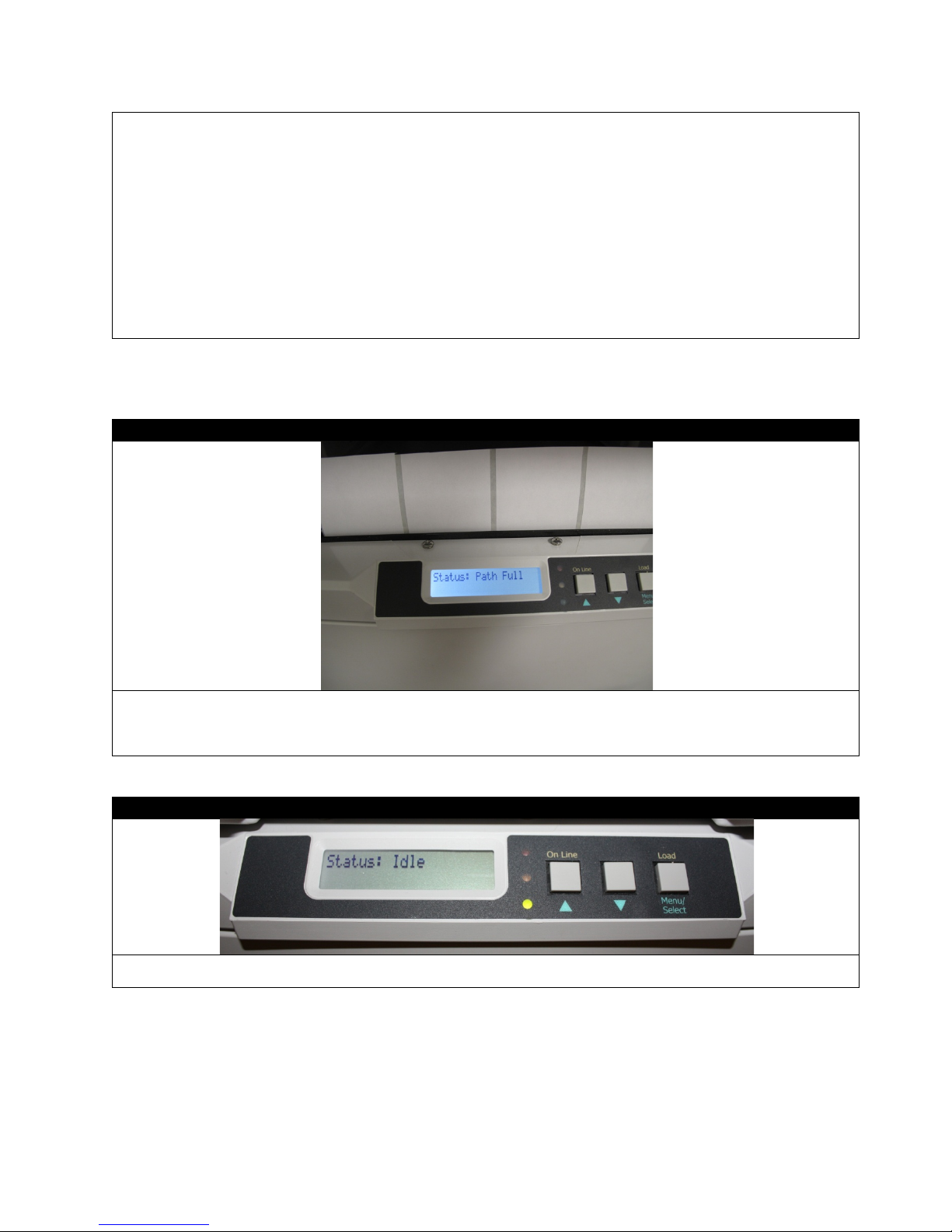
Close the front lid and push the paper tray back into place.
Press the On Line button and the calibration test will begin.
STEP 5 of 6
After the calibration process, press the On Line button to turn the machine Offline, and then hold the DOWN button to
Note: If you press Load at this moment, the machine might show Path Full because of the excess paper.
STEP 6 of 6
Remove the paper. Press the On Line b utto n again and select Load. After this, the machin e w ill show Idle and is ready
to use now that the calibration is done.
Using the Feeder Display Menu, do the following actions in sequence:
a.) Press the On Line button to take the printer Offline.
b.) Press Menu twice to get to M2: Calibrations.
c.) Press the UP arrow button to get to I3: Reg Sensor. Hold down the Menu button until the * disappears.
d.) Press Menu twice to get to the sensor type. Use the UP and/or DOWN buttons to set the Gap. Then hold
Menu until it stops flashing.
e.) Press the UP arrow to scroll to I4: RSEN AutoCal and hold Menu until Ready starts flashing.
f.) Press the UP arrow to select Execute and hold Menu until it stops flashing.
g.) Press Menu again and it will show Status: Offline
cut the excess paper after the calibrat ion is comple te.
92

93

How to Access the Settings as an Administrator
You can set whether to ENABLE or DISABLE each category in the user menu.
Disabled categories are not displayed in the User’s menu. Only a system administrator can change these settings.
1. Turn OFF the printer. Turn ON the printer while pressing the Enter button. When Boot Menu appears, take your
finger off the button.
2. Press the Enter button.
3. At the Enter Password prompt, enter the 4-9 digit Admin password. (The default password is aaaaaa).
(a) Using the up and down MENU buttons, scroll to the required letter/digit.
(b) Press the Enter button to input and move to the next letter/digit.
(c) Repeat steps (a) and (b) until all letters/digits are entered.
4. Press the Enter button.
5. Press the UP or DOWN arrow button until the “category” you want to change is displayed.
6. Press the Enter button.
7. Press the UP or DOWN arrow button until the “item” you want to change is displayed.
8. Press the Enter button.
9. Using the UP or DOWN arrow button, identify the parameter as required.
10. Press the Enter button to enter an asterisk (*) on the right side of the setting selected.
11. Press the Online button to switch to online. The mac hine will automatically re-boot.
94

Paper Sensor Error Codes
Code #
Location
380
Paper Feed Upper
381
Paper Transport
382
Paper Exit
385
Fuser
392
Paper Feed Lower
10 - 11
Load Sensors
Message
Issue
Msg: Guide Door Open
Ensure Guide Door is Closed
Push Guide Tray Completely into the Feeder.
Msg: Close Guide Tray
Ensure Guide Door is Closed
Msg: Close Door/Tray
Push Guide Tray Completely into the Feeder.
Msg: Funnel Full
Remove all Paper from the Guide.
Msg: Path Full
Remove all Paper from the Guide.
10-11
380
381
385
392
382
Feeder Panel Error Messages:
Msg: Guide Tray Out
Ensure Guide Tray Latches are Locked.
Ensure Guide Tray Latches are Locked.
95

Feeder Panel Errors:
Error
Issue
Solution
Emergency stop (guide door opened during
Status: Error 01
Switch panel communication error
Contact your dealer/reseller
Status: Error 02
Internal error
Contact your dealer/reseller
Status: Error 03
Internal error
Contact your dealer/reseller
Media not found over lower load sensor
Do a sensor calibration(p.57 in the manual)
Media not positioned between load sensors
Cutter did not leave home position in
Cutter did not finish cut in required time or
Status: Error 00
Status: Error 10
Status: Error 11
Status: Error 31
Status: Error 32
motor movement)
after load
properly after load advance
required time
can't home it
Close Door on Feeder
or remove paper in path
Check that media tension is not too tight
Check paper jam in cutter
Check paper jam in cutter
96
 Loading...