

Unimig RAZOR TIG 200 AC/DC Operating Manual

OPERATING MANUAL
3 YEAR
KUM-M-RTIG200ACDC
Please read and understand this instruction manual carefully
before the installation and operation of this equipment. © Welding Guns Of Australia PTY LTD 2019
WARRANTY
(POWER SOURCE)

WARRANTY
Thank you for your purchase of your RAZOR TIG 200 AC/DC Welding Machine.
We are proud of our range of plasma cutting and welding equipment that has a proven track record of innovation, performance and reliability.
Our product range represents the latest developments in Inverter technology put together by our professional team of highly skilled engineers. The
expertise gained from our long involvement with inverter technology has proven to be invaluable towards the evolution and future development of our
equipment range. This experience gives us the inside knowledge on what the arc characteristics, performance and interface between man and machine
should be.
Within our team are specialist welders that have a proven history of welding knowledge and expertise, giving vital input towards ensuring that our
machines deliver control and performance to the utmost professional level.
We employ an expert team of professional sales, marketing and technical personnel that provide us with market trends, market feedback and customer
comments and requirements. Secondly they provide a customer support service that is second to none, thus ensuring our customers have condence
that they will be well satised both now and in the future.
UNIMIG welders and plasma cutters are manufactured to be compliant with - AS/NZ 60974-1, guaranteeing you electrical safety and performance.
WARRANTY
• 3 Years from date of purchase.
• Welding Guns Of Australia PTY LTD Ltd warranties all goods as specied by the manufacturer of those goods.
• This Warranty does not cover freight or goods that have been interfered with.
• All goods in question must be repaired by an authorised repair agent as appointed by this company.
• Warranty does not cover abuse, misuse, accident, theft, general wear and tear.
• New product will not be supplied unless Welding Guns Of Australia PTY LTD has inspected product returned for warranty and agrees to replace product.
• Product will only be replaced if repair is not possible
• Please view full Warranty term and conditions supplied with machine or at www.unimig.com.au/warranty-registration/ or at the back of this manual.
REGISTER YOUR MACHINE ONLINE TO RECEIVE AN
ADDITIONAL 6 MONTHS ON YOUR WARRANTY
Visit unimig.com.au/warranty-registration/ to register your machine.
2 | RAZOR TIG 200 AC/DC Manual

CONTENTS
WARRANTY 2
SAFETY 4
RAZOR TIG 200 AC/DC FEATURES 8
RAZOR TIG 200 AC/DC TECHNICAL DATA 9
MACHINE PARTS LAYOUT 10
FRONT PANEL OPERATION 11
WELD PROGRAM OPERATION 12
ADDITIONAL FRONT PANEL OPERATION 13
H/F DC TIG SETUP 14
DC TIG WELDING GUIDE 15
DC PULSE TIG SETUP 17
MANUAL TIG WELDING TECHNIQUE 18
H/F AC TIG SETUP 19
AC SQUARE WAVE FREQUENCY CONTROL 20
AC TIG WELDING GUIDE 21
AC PULSE TIG SETUP 23
TUNGSTEN ELECTRODES 25
MMA (STICK) WELDING SET UP 28
MMA (STICK) WELDING GUIDE 29
T2 TIG TORCH & SPARES 31
T2 TIG TORCH TUNGSTEN ELECTRODES 33
TIG WELDING TROUBLE SHOOTING 34
MMA (STICK) WELDING TROUBLE SHOOTING 35
WARRANTY TERMS 36
NOTES 39
RAZOR TIG 200 AC/DC Manual | 3

SAFETY
Welding and cutting equipment can be dangerous to both the operator and people in or near the surrounding working area, if the equipment is not
correctly operated. Equipment must only be used under the strict and comprehensive observance of all relevant safety regulations.
Read and understand this instruction manual carefully before the installation and operation of this equipment.
Machine Operating Safety
• Do not switch the function modes while the machine is operating. Switching of the function modes during welding can damage the
machine. Damage caused in this manner will not be covered under warranty.
• Disconnect the electrode-holder cable from the machine before switching on the machine, to avoid arcing should the electrode be in
contact with the work piece.
• Operators should be trained and or qualied.
Electric shock: It can kill. Touching live electrical parts can cause fatal shocks or severe burns. The electrode and work circuit is
electrically live whenever the output is on. The input power circuit and internal machine circuits are also live when power is on. In MIG/
MAG welding, the wire, drive rollers, wire feed housing, and all metal parts touching the welding wire are electrically live. Incorrectly
installed or improperly grounded equipment is dangerous.
• Connect the primary input cable according to Australian and New Zealand standards and regulations.
• Avoid all contact with live electrical parts of the welding/cutting circuit, electrodes and wires with bare hands.
• The operator must wear dry welding gloves while he/she performs the welding/cutting task.
• The operator should keep the work piece insulated from himself/herself.
• Keep cords dry, free of oil and grease, and protected from hot metal and sparks.
• Frequently inspect input power cable for wear and tear, replace the cable immediately if damaged, bare wiring is dangerous and can
kill.
• Do not use damaged, under sized, or badly joined cables.
• Do not drape cables over your body.
• We recommend (RCD) safety switch is used with this equipment to detect any leakage of current to earth.
Fumes and gases are dangerous. Smoke and gas generated whilst welding or cutting can be harmful to people’s health. Welding
produces fumes and gases. Breathing these fumes and gases can be hazardous to your health.
Do not breathe the smoke and gas generated whilst welding or cutting, keep your head out of the fumes
• Keep the working area well ventilated, use fume extraction or ventilation to remove welding/cutting fumes and gases.
• In conned or heavy fume environments always wear an approved air-supplied respirator.
• Welding/cutting fumes and gases can displace air and lower the oxygen level causing injury or death. Be sure the breathing air is safe.
• Do not weld/cut in locations near de-greasing, cleaning, or spraying operations. The heat and rays of the arc can react with vapours to
form highly toxic and irritating gases.
• Materials such as galvanized, lead, or cadmium plated steel, containing elements that can give off toxic fumes when welded/cut. Do
not weld/cut these materials unless the area is very well ventilated, and or wearing an air supplied respirator.
Arc rays: harmful to people’s eyes and skin. Arc rays from the welding/cutting process produce intense visible and invisible ultraviolet
and infrared rays that can burn eyes and skin.
Always wear a welding helmet with correct shade of lter lens and suitable protective clothing including welding gloves whilst the
welding/cutting operation is performed.
• Measures should be taken to protect people in or near the surrounding working area. Use protective screens or barriers to protect
others from ash,glare and sparks; warn others not to watch the arc.
4 | RAZOR TIG 200 AC/DC Manual
SAFETY
Fire hazard. Welding/cutting on closed containers, such as tanks,drums, or pipes, can cause them to explode. Flying sparks from the
welding/cutting arc, hot work piece, and hot equipment can cause res and burns. Accidental contact of electrode to metal objects can
cause sparks, explosion, overheating, or re. Check and be sure the area is safe before doing any welding/cutting.
• The welding/cutting sparks & spatter may cause re, therefore remove any ammable materials well away from the working area.
• Do not weld/cut on closed containers such as tanks, drums, or pipes, unless they are properly prepared according to the required
• Do not weld/cut where the atmosphere may contain ammable dust, gas, or liquid vapours (such as petrol)
• Have a re extinguisher nearby and know how to use it. Be alert that welding/cutting sparks and hot materials from welding/cutting
Gas Cylinders. Shielding gas cylinders contain gas under high pressure. If damaged, a cylinder can explode. Because gas cylinders are
normally part of the welding/cutting process, be sure to treat them carefully. CYLINDERS can explode if damaged.
• Protect gas cylinders from excessive heat, mechanical shocks, physical damage, slag, open ames, sparks, and arcs.
• Insure cylinders are held secure and upright to prevent tipping or falling over.
• Never allow the welding/cutting electrode or earth clamp to touch the gas cylinder, do not drape welding cables over the cylinder.
• Never weld/cut on a pressurised gas cylinder, it will explode and kill you.
• Open the cylinder valve slowly and turn your face away from the cylinder outlet valve and gas regulator.
Gas build up. The build up of gas can causes a toxic environment, deplete the oxygen content in the air resulting in death or injury. Many
gases use in welding/cutting are invisible and odourless.
• Shut off shielding gas supply when not in use.
• Always ventilate conned spaces or use approved air-supplied respirator.
Electronic magnetic elds. MAGNETIC FIELDS can affect Implanted Medical Devices.
• Wearers of Pacemakers and other Implanted Medical Devices should keep away.
• Implanted Medical Device wearers should consult their doctor and the device manufacturer before going near any electric welding,
Noise can damage hearing. Noise from some processes or equipment can damage hearing.
• Wear approved ear protection if noise level is high.
Cover ammable materials and containers with approved covers if unable to be moved from the welding/cutting area.
Safety Standards to insure that ammable or toxic vapours and substances are totally removed, these can cause an explosion even
though the vessel has been “cleaned”. Vent hollow castings or containers before heating, cutting or welding. They may explode.
can easily go through small cracks and openings to adjacent areas. Be aware that welding/cutting on a ceiling, oor, bulkhead, or
partition can cause re on the hidden side.
cutting or heating operation.
Hot parts. Items being welded/cut generate and hold high heat and can cause severe burns.
Do not touch hot parts with bare hands. Allow a cooling period before working on the welding/cutting gun. Use insulated welding gloves
and clothing to handle hot parts and prevent burns.
RAZOR TIG 200 AC/DC Manual | 5

SAFETY
CAUTION
1. Working Environment.
i. The environment in which this welding/cutting equipment is installed must be free of grinding dust, corrosive chemicals, ammable gas or
materials etc, and at no more than maximum of 80% humidity.
ii. When using the machine outdoors protect the machine from direct sun light, rain water and snow etc; the temperature of working environment
should be maintained within -10°C to +40°C.
iii. Keep this equipment 30cm distant from the wall.
iv. Ensure the working environment is well ventilated.
2. Safety Tips.
i. Ventilation
This equipment is small-sized, compact in structure, and of excellent performance in amperage output. The fan is used to dissipate heat
generated by this equipment during the welding/cutting operation. Important: Maintain good ventilation of the louvres of this equipment. The
minimum distance between this equipment and any other objects in or near the working area should be 30 cm. Good ventilation is of critical
importance for the normal performance and service life of this equipment.
ii. Thermal Overload protection.
Should the machine be used to an excessive level, or in high temperature environment, poorly ventilated area or if the fan malfunctions the
Thermal Overload Switch will be activated and the machine will cease to operate. Under this circumstance, leave the machine switched on to
keep the built-in fan working to bring down the temperature inside the equipment. The machine will be ready for use again when the internal
temperature reaches safe level.
iii. Over-Voltage Supply
Regarding the power supply voltage range of the machine, please refer to “Main parameter” table. This equipment is of automatic voltage
compensation, which enables the maintaining of the voltage range within the given range. In case that the voltage of input power supply
amperage exceeds the stipulated value, it is possible to cause damage to the components of this equipment. Please ensure your primary
power supply is correct.
iv. Do not come into contact with the output terminals while the machine is in operation. An electric shock may possibly occur.
MAINTENANCE
Exposure to extremely dusty, damp, or corrosive air is damaging to the welding/cutting machine. In order to prevent any possible failure or fault of this
welding/cutting equipment, clean the dust at regular intervals with clean and dry compressed air of required pressure.
Please note that: lack of maintenance can result in the cancellation of the guarantee; the guarantee of this welding/cutting equipment will be void if the
machine has been modied, attempt to take apart the machine or open the factory-made sealing of the machine without the consent of an authorized
representative of the manufacturer.
TROUBLE SHOOTING
Caution: Only qualied technicians are authorized to undertake the repair of this welding/cutting equipment. For your safety and to avoid Electrical
Shock, please observe all safety notes and precautions detailed in this manual.
6 | RAZOR TIG 200 AC/DC Manual

SAFETY
ATTENTION! - CHECK FOR GAS LEAKAGE
At initial set up and at regular intervals we recommend to check for gas leakage
Recommended procedure is as follows:
1. Connect the regulator and gas hose assembly and tighten all connectors and clamps.
2. Slowly open the cylinder valve.
3. Set the ow rate on the regulator to approximately 8-10 L/min.
4. Close the cylinder valve and pay attention to the needle indicator of the contents pressure gauge on the regulator, if the needle drops away towards
zero there is a gas leak. Sometimes a gas leak can be slow and to identify it will require leaving the gas pressure in the regulator and line for an
extended time period. In this situation it is recommended to open the cylinder valve, set the ow rate to 8-10 L/min, close the cylinder valve and check
after a minimum of 15 minutes.
5. If there is a gas loss then check all connectors and clamps for leakage by brushing or spraying with soapy water, bubbles will appear at the leakage
point.
6. Tighten clamps or ttings to eliminate gas leakage.
IMPORTANT! - We strongly recommend that you check for gas leakage prior to operation of your machine. We recommend that you close the
cylinder valve when the machine is not in use.
Welding Guns Of Australia PTY LTD, authorised representatives or agents of Welding Guns Of Australia PTY LTD will not be liable or responsible for
the loss of any gas.
RAZOR TIG 200 AC/DC Manual | 7
RAZOR TIG 200 AC/DC FEATURES
3 YEAR
WARRANTY
(POWER SOURCE)
FEATURES
• 15 AMP Plug
• AC/DC H/F TIG & PULSE TIG
- Pre Gas 0.1 - 3.0 sec
- Start Amperage 10 - 200A
- Up Slope 0 - 10 sec
- Peak Amp 10 - 200A
- AC Square Wave 20 - 250Hz
- AC Balance Control ±10
- Down Slope 0 - 15 sec
- Adjustable Finish Amperage 10 - 200A
- Post Gas 0.5 - 15.0 sec
• STICK (MMA) with ARC FORCE
• Thermal overload protection
• IP21S rating for environmental/safety protection
• Generator compatible (recommend KVA minimum)
• VRD (Voltage Reduction Device)
• Foot Control Ready
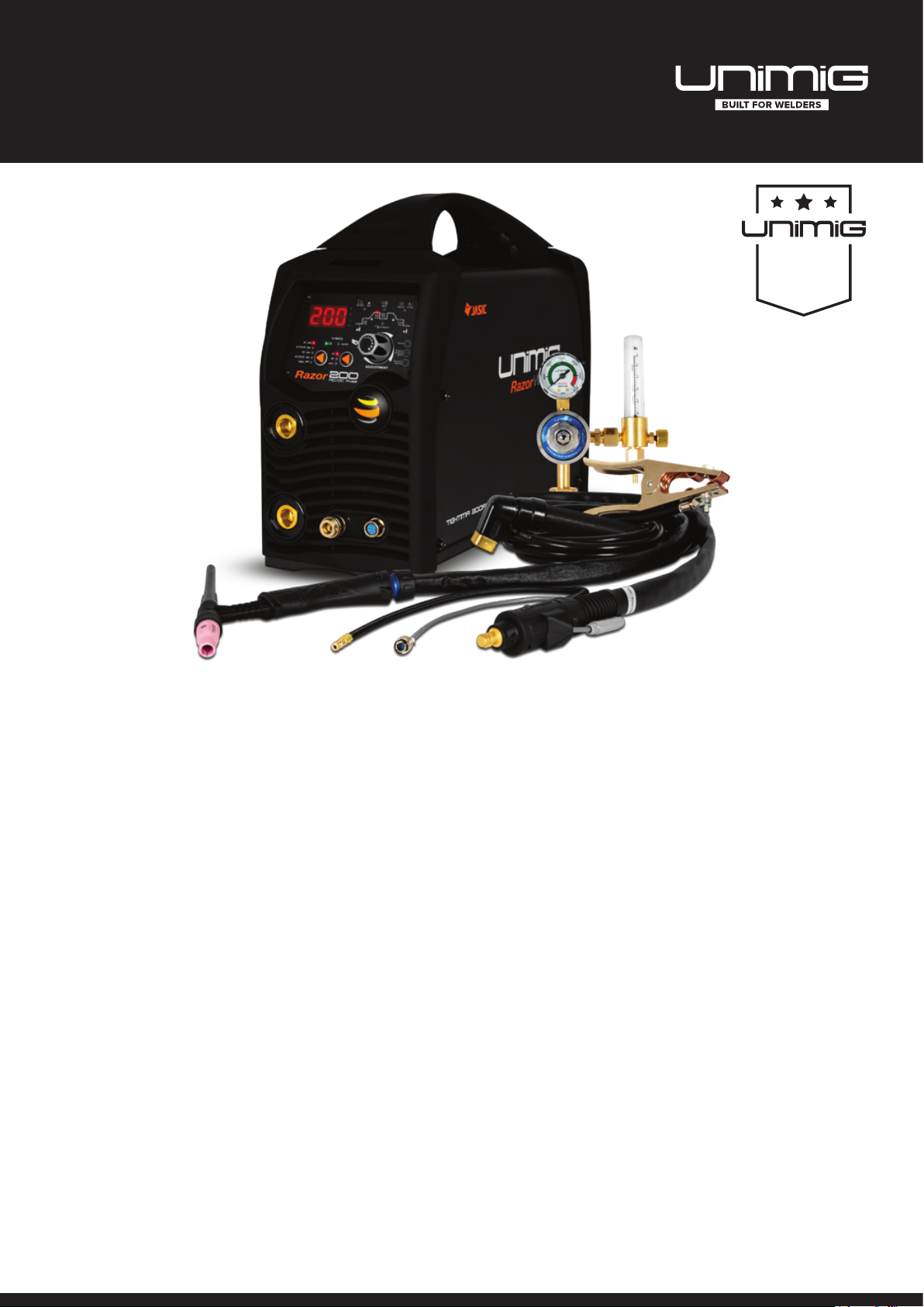
OVERVIEW
The RAZOR TIG 200 AC/DC is the perfect AC/DC TIG & STICK Welder for professional
welder wanting both AC and DC TIG welding capabilities. Fitted with a 15 AMP Plug,
this machine is suited to light to medium industrial work.
The RAZOR TIG 200 AC/DC allows for full control over the TIG welding process to
ensure you can maximise your results from start to nish. Controllable parameters
include Pre Gas Time, Start Current, Up Slope and Down Slope Time, Finish Current
Level and Post Gas Time, among many others.
The all-new ARC TORCHOLOGY T2 TIG Torch comes standard with the RAZOR TIG
200 AC/DC, offering up to 30% more power and longer consumable life-cycles. A
Remote Foot Control (UTJRFC-4) can also be plugged into the machine for even more
versatility.
With all of these features packed into an compact package, the RAZOR TIG 200 AC/
DC is a must-have for any professional welder or TIG enthusiast.
MACHINE PACKAGE: KUM-M-RTIG200ACDC
• RAZOR TIG 200 AC/DC Power Source
• 4m High Performance T2 TIG Torch (including consumables)
• 4m Twist Lock Electrode Holder
• 300 Amp Earth Clamp & Lead
• Argon Flowmeter Regulator
• 2m Gas Hose Complete with ttings
• Operating Manual
8 | RAZOR TIG 200 AC/DC Manual

RAZOR TIG 200 AC/DC TECHNICAL DATA
TECHNICAL DATA
MACHINE RAZOR TIG 200 AC/DC
SKU KUM-M-RTIG200ACDC
PRIMARY INPUT VOLTAGE 240V Single Phase
SUPPLY PLUG 15 AMP
RATED INPUT POWER (kVA) 6.0
Ieff (A) 15.0
Imax (A) 29.0
RATED OUTPUT 10-200A/18.0V
NO LOAD VOLTAGE (V) 9-68
PROTECTION CLASS IP21S
INSULATION CLASS F
POWER FACTOR 0.7
MINIMUM GENERATOR (kVA) 9.0
DINSE CONNECTOR 35/50
STANDARD AS/NZ60974-1
Mild Steel, Stainless Steel, Cast Iron,
WELDS
WARRANTY (Years) 3
Silicon Bronze, Copper, Aluminium, Zinc
Alloys
STICK SPECIFICATIONS
STICK WELDING CURRENT RANGE 10-160A
STICK DUTY CYCLE @ 40°C 30% @ 160A
STICK ELECTRODE RANGE 2.5-4.0mm
STICK WELDING THICKNESS
RANGE
ARC FORCE 0-40
2mm - 12mm
SIZE & WEIGHT
DIMENSIONS (mm) 426x162x326mm
WEIGHT (kg) 10kg
MACHINE FEATURES
VRD Yes
FOOT CONTROL READY Yes (UTJCFC-4)
CRATER CURRENT CONTROL Yes
THERMAL OVERLOAD
PROTECTION
Yes
TIG SPECIFICATIONS
TIG FUNCTION TYPE AC/DC HF TIG & AC/DC Pulse
TIG WELDING CURRENT RANGE 10-200A
TIG DUTY CYCLE @ 40°C 25% @ 200A
TIG WELDING THICKNESS RANGE 1mm - 8mm
AC/DC TIG PARAMETERS
PRE GAS 0.1-3.0s
START AMP 10-200A
UP SLOPE 0-10s
PEAK AMP 10-200A
AC SQUARE WAVE 20-250Hz
AC BALANCE CONTROL ±10
DOWN SLOPE 0-15s
FINISH AMP 10-200A
POST GAS 0.5-15.0s
PULSE FREQUENCY 0.2-200Hz
PULSE WIDTH 10-90%
SPOT 0.5-10s
RAZOR TIG 200 AC/DC Manual | 9
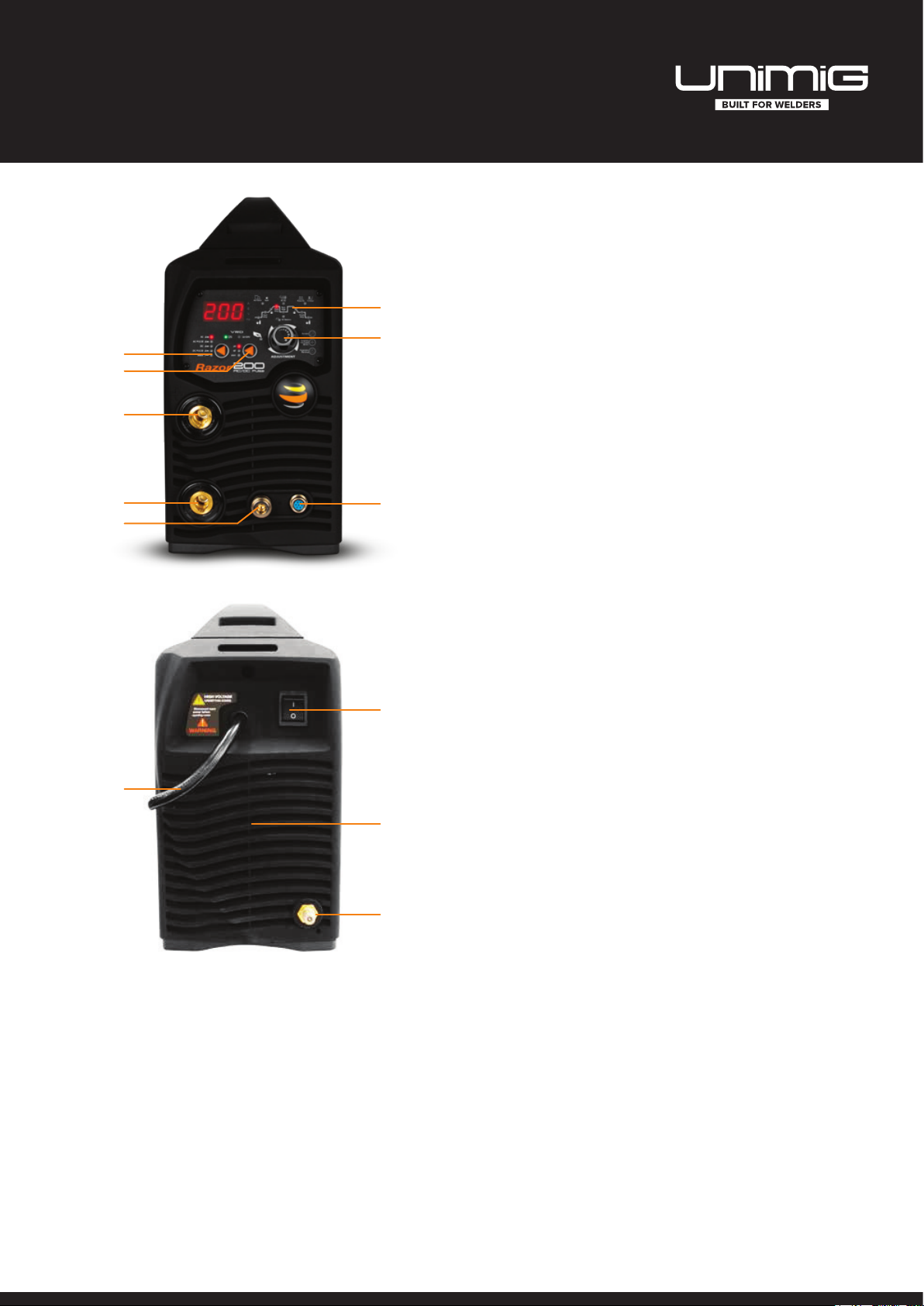
MACHINE PARTS LAYOUT
8
7
1
2
3
FRONT PANEL LAYOUT
1. Weld Function Selector
2. 2T / 4T / Spot Selector
3. Positive Output Terminal
4. Negative Output Terminal
5. Quick Lock Gas Connector
6. Torch Switch - Remote Connector
7. Encoder Knob
8. Weld Cycle Display
10
4
5
6
9
BACK PANEL LAYOUT
9. Power Switch
10. Mains Power Input Cable
11
12
11. Fan
12. Inlet Gas Connector
10 | RAZOR TIG 200 AC/DC Manual
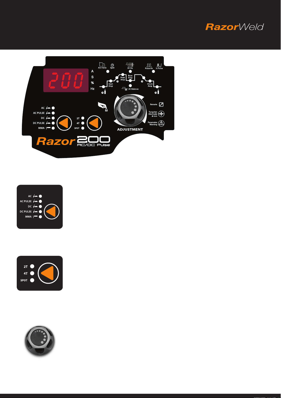
FRONT PANEL OPERATION
Mode Selector
Enables selection of required welding mode:
• AC TIG
• AC PULSE TIG
• DC TIG
• DC PULSE TIG
• DC MMA (Stick)
Torch Switch Mode Selector
Controls the on/off cycle of the machine using the torch switch while incorporating the weld program parameters selections:
• 2T uses 2 actions of the torch switch while incorporating the weld program parameter selections.
• 4T uses 4 actions of the torch switch while incorporating the weld program parameter selections. 4T provides operator control
of the start and nish portions of the weld sequence.
• Spot uses a single action of the torch switch. Pressing the torch switch gives arc ignition and initialises the welding sequence
for the period of time set using the spot timer.
Encoder Knob
Provides digital adjustment of welding parameters and provides step by step motion through the weld cycle parameters.
• Turn the knob to increase or decrease the desired value displayed on the LED display.
• Press the knob to cycle between each step of the weld cycle.
RAZOR TIG 200 AC/DC Manual | 11

WELD PROGRAM OPERATION
AC Balance
SpotArc Force
Start
Amp
Peak
Amp
Base
Amp
Finish
Amp
AC Hz Pulse Hz % Pulse
1
2 7
3 6
4
5
9
12 11
10
8
1. Pre Gas Timer
• Provides selection for gas ow time prior to the arc starting. (0.1 - 3.0s)
2. Start Amp
• Provides selection for the amount of amps required at the start of the weld.
(5 - 160 AMP)
3. Up Slope Time
• Sets the transition time from Start Amperage to Welding Amperage. (0-10s)
4. Peak Amp
• Provides selection for the Maximum Welding Amperage required during welding.
(5 - 180 AMP)
5. Base Amp
• Provides selection for the Base Amperage during the Pulse Welding cycle.
(5-180 AMP)
6. Down Slope Time
• Sets the transition time from Welding Amperage to Finish Amperage. (0 - 15s)
7. Finish Amp
• Provides selection for the amount of amperage required at the end of the weld.
(5-180 AMP)
8. Post Gas Timer
• Provides selection for continued gas ow time at the end of the welding after the
arc is out. (0.5-15s)
9. AC Balance
• Provides selection to adjust the balance of the AC wave form in AC TIG mode.
Allows adjustment of the arc to be balanced, penetrating or oxide cleaning during
AC TIG welding. (-5 to +5)
10. AC Hz
• Provides selection to adjust the frequency of the AC square wave in AC TIG mode.
Allows adjustment of frequency of the AC square wave cycle (transistion from + to
-) during AC TIG welding. (20-250 Hz)
11. Pulse Hz / % Pulse
• The Pulse Hz / % Pulse combines two functions under the same section. Upon
rst illuminating, the display will refer to he Pulse Hz value. Push the Encoder Knob
once more to display the % Pulse value.
PULSE HZ
• Provides selection of the pulse frequency of the welding output current. Allows
adjustment of frequency that the output current transistions from Peak Amp to
Base Amp. (0.02-200 Hz)
% PULSE
• Provides selection of the on time ratio of the Peak Amp during the pulse welding
cycle (Pulse Width). Allows adjustment of the % of time that the Peak Amp is on
during each pulse cycle. (10-90%)
12. Spot / Arc Force
• The Spot / Arc Force combines two functions under the same section. When in TIG
Mode, and SPOT is selected from the Torch Switch Mode Slector, the section will
refer to Spot. When in MMA Mode, the section will refer to Arc Force.
SPOT
• Provides selection of a pre-set time period for welding current output. Allows
adjustment of the time that machine will deliver amperage output from trigger
activation. (0.5-10s)
ARC FORCE
• Provides selection for adjustment of the ARC FORCE during MMA (Stick) welding.
Low value allows a soft arc, a higher value allows stronger digging arc. (0-40)
12 | RAZOR TIG 200 AC/DC Manual
 Loading...