

Uni-Mig KUMJR200AC/DC Operating Manual
1
UNI-FLAME
UNI-FLAME AUTOLIFT
240 Volt
Standard
MIG / MAG
Lift Arc DC/TIG
Plasma CUT
Lift Arc DC/TIG
YEARS Warranty
(Power Source)
2
Please read and understand this instruction manual carefully
before the installation and operation of this equipment.
OPERATING MANUAL
KUMJR200AC/DC
©
Welding Guns Of Australia PTY LTD 2012

2
Thank you for your purchase of your UNI-MIG welding machine.
We are proud of our range of welding equipment that has a proven track record of innovation,
performance and reliability.
Our product range represents the latest developments in Inverter technology that have been
implemented by our professional team of highly skilled engineers. The expertise gained from our
long history of sales has proven to be invaluable to the evolution and future development of our
equipment range. This experience gives us the inside knowledge on what the arc characteristics,
performance and interface between man and machine should be.
We employ an expert team of professional sales, marketing and technical personnel that provide
us with market trends, market feedback and customer comments and requirements. Secondly they
provide a customer support service that is second to none, thus ensuring our customers have
condence that they will be well satised both now and in the future.
UNI-MIG welders are manufactured to comply with - AS/NZ60974.1 2006 - AS60974-6:2006
WARRANTY
• 2 Years from date of purchase.
• Welding Guns Of Australia PTY LTD Ltd warranties all goods as specified by the manufacturer
of those goods.
• This Warranty does not cover freight or goods that have been interfered with.
• All goods in question must be repaired by an authorised repair agent as appointed by this
company.
• Warranty does not cover abuse, mis-use, accident, theft, general wear and tear.
• New product will not be supplied unless Welding Guns Of Australia PTY LTD has inspected
product returned for warranty and agree’s to replace product.
• Product will only be replaced if repair is not possible
• Please view full Warranty term and conditions supplied with machine or at www.unimig.com.au/
warranty.asp or at the back of this manual.

3
CONTENTS PAGE
Warranty 2
Safety - Cautions 4-6
Technical Data, Product Information 7
Machine Layout & Descriptions 8
Front Panel Selector Switch Function Descriptions 9
Front Panel Control Dial Function Descriptions 10-11
Machine Installation & Operation 13
Installation & Operation for MMA (Stick) Welding 14-15
MMA (Stick) Welding 16-17
Installation & Operation for DC TIG Welding 18-19
DC TIG Welding, DC Pulse TIG Welding 20-22
TIG Welding Fusion and Filler Wire Technique 23
Installation & Operation for AC TIG Welding 24-25
AC TIG Welding, AC Pulse TIG Welding 26-28
Remote Controls - Installation and Operation 29
Tungsten Electrode Selection & Preparation 30-32
Trouble Shooting Guide - MMA (Stick) Welding 33
Trouble Shooting Guide - TIG Welding 34-35
TIG Torch Parts Breakdown 36-37
Machine Spare Parts Identication 38-39
4
SAFETY
Welding and cutting equipment can be dangerous to both the operator and people in or near the
surrounding working area, if the equipment is not correctly operated. Equipment must only be
used under the strict and comprehensive observance of all relevant safety regulations.
Read and understand this instruction manual carefully before the installation and operation of this
equipment.
• Do not switch the function modes while the machine is operating. Switching of the function modes during
welding can damage the machine. Damage caused in this manner will not be covered under warranty.
• Disconnect the electrode-holder cable from the machine before switching on the machine, to avoid arcing
should the electrode be in contact with the work piece.
• Operators should be trained and or qualied.
Electric shock: It can kill. Touching live electrical parts can cause fatal shocks or severe
burns. The electrode and work circuit is electrically live whenever the output is on. The input
power circuit and internal machine circuits are also live when power is on. In Mig/Mag welding,
the wire, drive rollers, wire feed housing, and all metal parts touching the welding wire are
electrically live. Incorrectly installed or improperly grounded equipment is dangerous.
• Connect the primary input cable according to Australian and New Zealand standards and regulations.
• Avoid all contact with live electrical parts of the welding circuit, electrodes and wires with bare hands.
The operator must wear dry welding gloves while he/she performs the welding task.
• The operator should keep the work piece insulated from himself/herself.
• Keep cords dry, free of oil and grease, and protected from hot metal and sparks.
• Frequently inspect input power cable for wear and tear, replace the cable immediately if damaged,
bare wiring is dangerous and can kill.
• Do not use damaged, under sized, or badly joined cables.
• Do not drape cables over your body.
Fumes and gases are dangerous. Smoke and gas generated whilst welding or cutting can
be harmful to people’s health. Welding produces fumes and gases. Breathing these fumes and
gases can be hazardous to your health.
• Do not breathe the smoke and gas generated whilst welding or cutting, keep your head out of the fumes
• Keep the working area well ventilated, use fume extraction or ventilation to remove welding fumes and
gases.
• In conned or heavy fume environments always wear an approved air-supplied respirator.
Welding fumes and gases can displace air and lower the oxygen level causing injury or death. Be sure the
breathing air is safe.
• Do not weld in locations near de-greasing, cleaning, or spraying operations. The heat and rays of the arc
can react with vapours to form highly toxic and irritating gases.
• Materials such as galvanized, lead, or cadmium plated steel, containing elements that can give off toxic
fumes when welded. Do not weld these materials unless the area is very well ventilated, and or wearing
an air supplied respirator.
Arc rays: harmful to people’s eyes and skin. Arc rays from the welding process produce
intense visible and invisible ultraviolet and infrared rays that can burn eyes and skin.
• Always wear a welding helmet with correct shade of lter lens and suitable protective clothing including
welding gloves whilst the welding operation is performed.
• Measures should be taken to protect people in or near the surrounding working area. Use protective
screens or barriers to protect others from ash,glare and sparks; warn others not to watch the arc.
Machine Operating Safety
5
Fire hazard. Welding on closed containers, such as tanks,drums, or pipes, can cause them
to explode. Flying sparks from the welding arc, hot work piece, and hot equipment can cause
res and burns. Accidental contact of electrode to metal objects can cause sparks, explosion,
overheating, or re. Check and be sure the area is safe before doing any welding.
• The welding sparks may cause re, therefore remove any ammable materials away from the working
area, at least 12m from the welding arc. Cover ammable materials and containers with approved covers
if unable to be moved from the welding area.
• Do not weld on closed containers such as tanks, drums, or pipes, unless they are properly prepared
according to the required Safety Standards to insure that ammable or toxic vapors and substances are
totally removed, these can cause an explosion even though the vessel has been “cleaned”.
Vent hollow castings or containers before heating, cutting or welding. They may explode.
• Do not weld where the atmosphere may contain ammable dust, gas, or liquid vapours (such as petrol)
• Have a re extinguisher nearby and know how to use it. Be alert that welding sparks and hot materials
from welding can easily go through small cracks and openings to adjacent areas. Be aware that welding
on a ceiling, oor, bulkhead, or partition can cause re on the hidden side.
Gas Cylinders. Shielding gas cylinders contain gas under high pressure. If damaged, a cylinder can explode. Because gas cylinders are normally part of the welding process, be sure to
treat them carefully. CYLINDERS can explode if damaged.
• Protect gas cylinders from excessive heat, mechanical shocks, physical damage, slag, open ames,
sparks, and arcs.
• Insure cylinders are held secure and upright to prevent tipping or falling over.
• Never allow the welding electrode or earth clamp to touch the gas cylinder, do not drape welding cables
over the cylinder.
• Never weld on a pressurised gas cylinder, it will explode and kill you.
• Open the cylinder valve slowly and turn your face away from the cylinder outlet valve and gas regulator.
Gas build up. The build up of gas can causes a toxic environment, deplete the oxygen content
in the air resulting in death or injury. Many gases use in welding are invisible and odourless.
• Shut off shielding gas supply when not in use.
• Always ventilate conned spaces or use approved air-supplied respirator.
Electronic magnetic elds. MAGNETIC FIELDS can affect Implanted Medical Devices.
• Wearers of Pacemakers and other Implanted Medical Devices should keep away.
• Implanted Medical Device wearers should consult their doctor and the device manufacturer before going
near any electric welding, cutting or heating operation.
Noise can damage hearing. Noise from some processes or equipment can damage hearing.
Wear approved ear protection if noise level is high.
Hot parts. Items being welded generate and hold high heat and can cause severe burns.
Do not touch hot parts with bare hands. Allow a cooling period before working on the welding
gun. Use insulated welding gloves and clothing to handle hot parts and prevent burns.

6
CAUTION
1. Working Environment.
1.1 The environment in which this welding equipment is installed must be free of grinding dust, corrosive
chemicals, ammable gas or materials etc, and at no more than maximum of 80% humidity.
1.2 When using the machine outdoors protect the machine from direct sun light, rain water and snow etc;
the temperature of working environment should be maintained within -10°C to +40°C.
1.3 Keep this equipment 30cm distant from the wall.
1.4 Ensure the working environment is well ventilated.
2. Safety Tips.
2.1 Ventilation
This equipment is small-sized, compact in structure, and of excellent performance in amperage output.
The fan is used to dissipate heat generated by this equipment during the welding operation.
Important: Maintain good ventilation of the louvers of this equipment. The minimum distance between
this equipment and any other objects in or near the working area should be 30 cm. Good ventilation is
of critical importance for the normal performance and service life of this equipment.
2.2
Thermal Overload protection.
Should the machine be used to an excessive level, or in high temperature environment, poorly
ventilated area or if the fan malfunctions the Thermal Overload Switch will be activated and the
machine will cease to operate. Under this circumstance, leave the machine switched on to keep the
built-in fan working to bring down the temperature inside the equipment. The machine will be ready for
use again when the internal temperature reaches safe level.
2.3
Over-Voltage Supply
Regarding the power supply voltage range of the machine, please refer to “Main parameter” table.
This equipment is of automatic voltage compensation, which enables the maintaining of the voltage
range within the given range. In case that the voltage of input power supply amperage exceeds the
stipulated value, it is possible to cause damage to the components of this equipment. Please ensure
your primary power supply is correct.
2.4 Do not come into contact with the output terminals while the machine is in operation. An electric shock
may possibly occur.
MAINTENANCE
Exposure to extremely dusty, damp, or corrosive air is damaging to the welding machine. In order to prevent any possible failure or fault of this welding equipment, clean the dust at regular intervals with clean and
dry compressed air of required pressure.
Please note that: lack of maintenance can result in the cancellation of the guarantee; the guarantee of
this welding equipment will be void if the machine has been modied, attempt to take apart the machine or
open the factory-made sealing of the machine without the consent of an authorized representative of the
manufacturer.
TROUBLE SHOOTING
Caution: Only qualied technicians are authorized to undertake the repair of this welding equipment.
For your safety and to avoid Electrical Shock, please observe all safety notes and precautions
detailed in this manual.
Note:
Minimum Motor Generator Power Suggested:- 10KVA
7
Technical Data
Power Supply / Phases (V-Ph) 240V - 1 ±15%
Rated Input Power (KVA) 5.8
ieff (Amps) 14.6 (TIG)
Rated Input Current (A) 24
Rated Output 20-170A/26.8V MMA
10-200A/17.4V TIG
No-Load Voltage (V) 56
Duty Cycle @ 40ºC as per AS/NZ60974 20%@170Amps MMA
20%@200Amps TIG
Efciency (%) 85
Power Factor 0.93
Protection Class IP21S
Insulation Class F
Size (mm) 510x330x360
Weight (kg) 30Kg
Warranty 2 years on power source
Overview
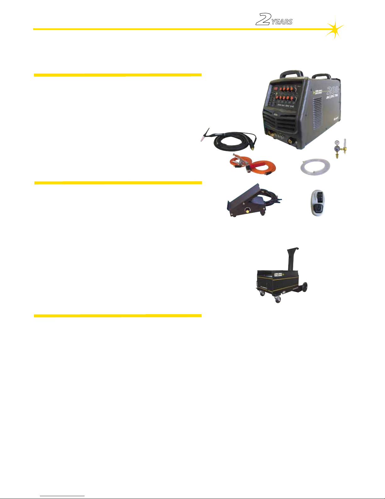
UTJRTROLLEY
Trolley Option
Welds: Aluminium, Zinc Alloy,Carbon Steels, Alloy Steels, Stainless, Cast Iron, Bronze, Copper
TIG 200Amp AC/DC Welding Machine
Square Wave, Pulse, Remote Control
Features
• Latest IGBT Inverter Technology
• AC/DC Tig (AC/DC tungsten inert gas welding)
• HF Tig Function (provides easy arc start, prevents tungsten damage)
• 2/4T Trigger Function
• AC Square Wave with Adjustable AC Balance Control
• Adjustable Pulse Control - 0.5 - 300Hz
• Adjustable Base Current 10-90%
• Adjustable Down Slope 0-10 sec
• Adjustable Post Gas 0-10 sec
• MMA (stick electrode)
• Hot start (improves electrode starting)
• Arc Force (stabilises the arc with difcult to use electrodes)
• Remote Amperage Control - Optional
UTJRFC
Remote Foot Control Option
The KUMJR200AC/DC is a 240V square wave AC/DC TIG inverter welder incorporating full TIG functionality including AC balance
control, pre gas, down slope, post gas, variable pulse parameters, HF start with 2/4T trigger control. The HF arc start provides easy
arc ignition leaving no tungsten inclusion and no contamination of the tungsten electrode. The Down Slope and Post Gas combined
with the 2/4T trigger function gives you control of the welder allowing you to control the start and nish of the weld process at a professional level. The addition of a fully adjustable pulse function of frequency, base current and pulse width gives you the added capability
to better control heat input into the work, control penetration & control distortion. AC balance control lets you set the AC TIG arc for
cleaning of the oxide layer on aluminium and adjustment for a deeper penetrating weld. Combining the functions of the KUMJR200AC/
DC ensures comprehensive control of the welding parameters when welding both AC and DC weldable materials giving you the abil-
ity to produce professional Tig welds. The DC MMA welding capability delivers a smooth and stable arc allowing easy welding with
electrodes obtaining high quality welds including cast Iron, stainless and low hydrogen. Addition of the optional Foot Control provides
variable amperage adjustment during welding. The UNI-MIG KUMJR200AC/DC has set the benchmark for 240V single phase AC/DC
welders and made it ideal for multiple applications; aluminium & stainless steel fabrication, light industrial use, repair and maintenance
applications.
Robust & reliable, built to our specication and manufactured in compliance to AS/NZ60974.1
Product Code: KUMJR200AC/DC
Standard option includes: KUMJR200AC/DC Machine, SR26 Tig Torch x 4m, Earth Lead & Arc Lead 25mm x 4m, Argon Regulator, 2M
Gas Hose with ttings
SRMS-10
Amperage Control fro torch
KUMJR200AC/DC
Certied - AS/NZ60974.1
YEARS Warranty
(Power Source)
2

8
Arc Force
Control Dial
Pulse Frequency
Control Dial
Pulse Width
Control Dial
AC Balance
Control Dial
Post Flow Gas
Control Dial
Down Slope
Control Dial
Base Current
Control Dial
Peak Current
Control Dial
Gas Pre Flow
Control Dial
Thermal Alarm
LED
Function Alarm
LED
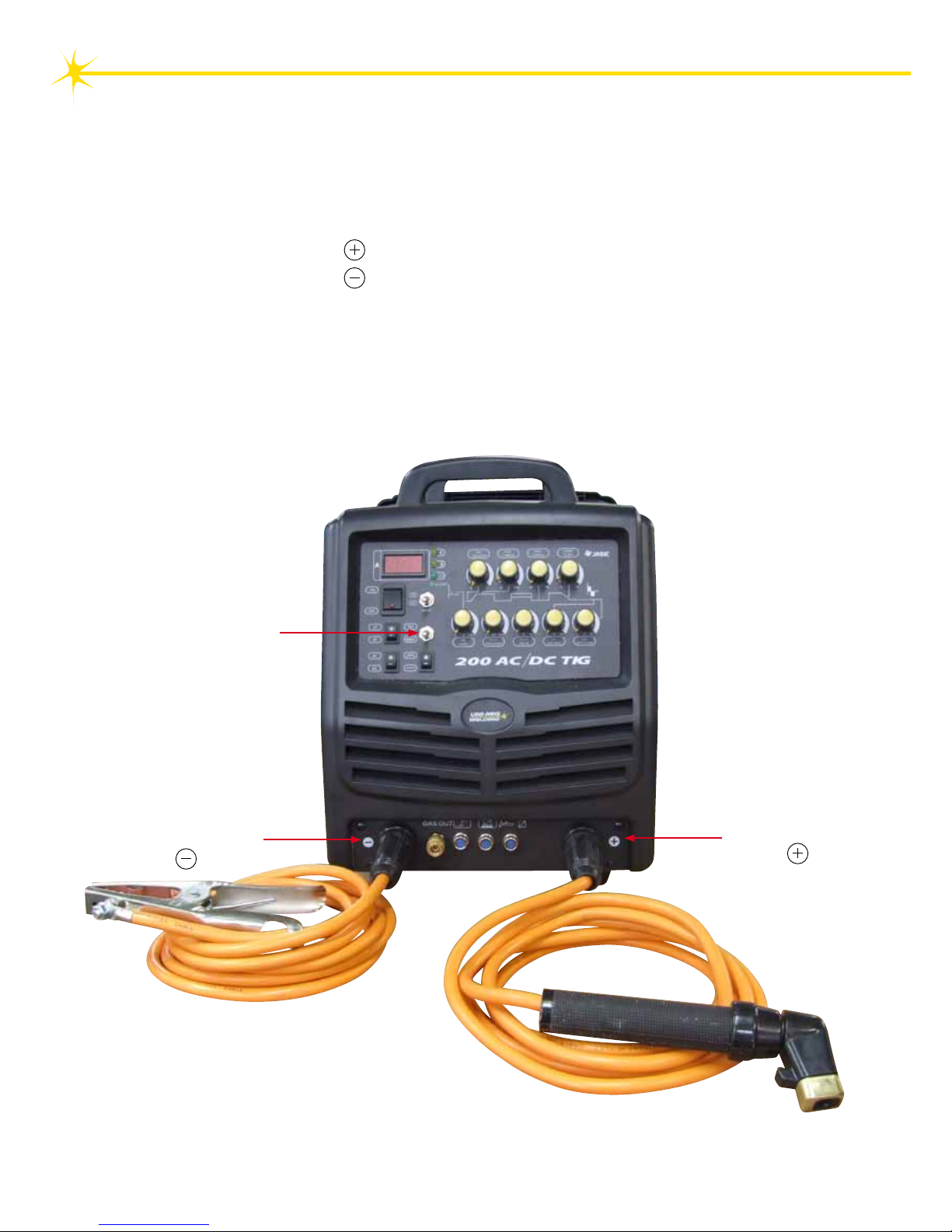
Amperage Display
Negative Output Terminal
Pulse Selector
AC/DC Selector
2T/4T Selector
TIG/MMA Selector
ON/OFF Switch
Remote Control Selector
Positive Output Terminal
Gas Out
Connector
Torch Remote
Control Socket
Torch Switch
Socket
Foot Amp
Control Socket
Input Gas Connector
Primary Power Input
Data Plate
Serial Number
Rear Machine Layout Description
Front Machine Layout Description
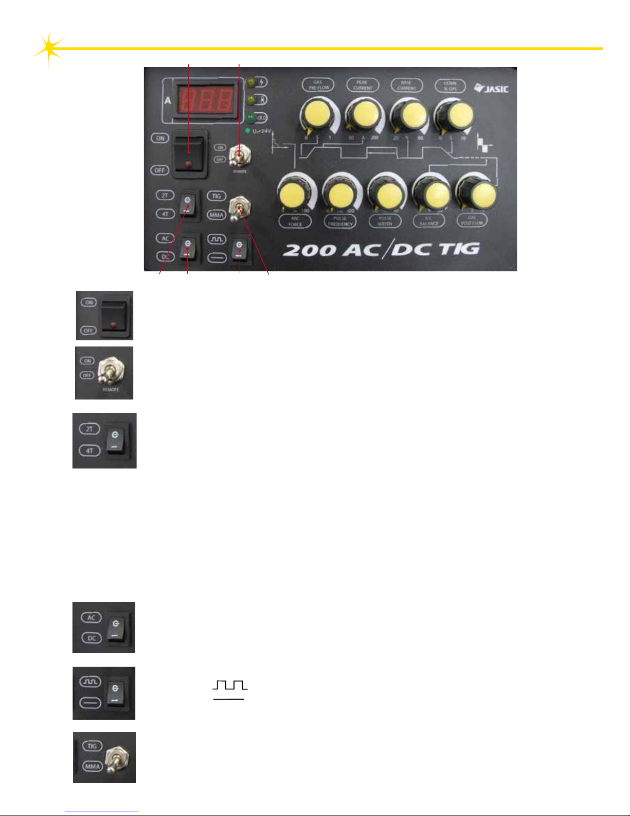
9
4 AC/DC: Provides selection of AC or DC Current.
Selecting the AC position provides for AC welding current output.
Selecting the DC position provides for DC welding current output.
1 2
3
4 5
6
1 ON/OFF: This switch powers the machine up when switched to the on position
and powers the machine off when switched to the off position.
3 2T/4T: Provides control over the arc ignition, weld cycle and nishing of the weld
using the torch trigger switch.
2T Selection provides 2 times function of the torch switch
(1) Pressing the torch switch gives arc ignition and initializes the welding current
(2) Releasing the torch switch introduces down slope time to minimum current level
and then terminates the welding current and introduces the post ow gas
4T Selection provides 4 times function of the torch switch
(1) Pressing the torch switch gives arc ignition and initializes the welding current
(2) Releasing the torch switch continues the welding operation.
(3) Pressing the torch switch introduces down slope and current falls to
minimum current
(4) Releasing the torch switch terminates the welding operation and introduces the
post ow gas.
6 TIG/MMA: Provides selection of TIG or MMA (Stick) welding modes.
Selecting the TIG position provides for TIG welding function.
Selecting the MMA position provides for Manual Metal Arc (Stick)welding function.
5 Pulse Selector: Provides selection of Pulse welding mode.
Selecting the position place the machine in Pulse welding mode.
Selecting the position place the machine in standard (non Pulse) welding.
mode.
2 Remote: Provides selection of the remote output current (amps) control function
Selecting the ON position allows use of the remote current (amperage) controls
Selecting the OFF postion allows current (amperage) control from the front panel
Peak current control.
Selector Switch Function Descriptions
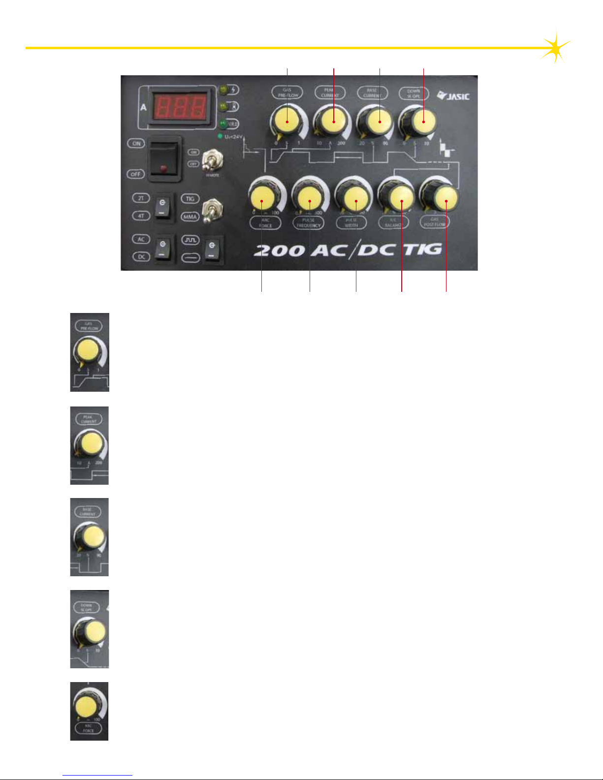
10
A B C D
E
F G
H
I
A Gas Pre Flow: Provides a pre-ow of gas to purge tig torch gas line prior to the
initialisation of the arc. Helps arc ignition and prevents porosity in the weld start.
Adjustment is 0-1sec.
B Peak Current: Provides adjustment and control of the main welding current.
Adjustment range 10-200 Amps.
C Base Current: Provides adjustment and control of the base welding current during
pulse welding. Represents a percentage of the Peak welding current, for example
Peak current set at 100 amps - Base Current set at 20% (20 amps)it means the output
current (amps) during the pulse cycle will go from 100 amps down to 20 amps during
each pulse cycle.
Adjustment range 20 - 90%.
D Down Slope: Provides adjustment of the down slope time at the end of the welding
cycle. At the end of the weld cycle the welding current will reduce down gradually
over the time set at the dial until it stops. This prevents craters and pin holes forming at
the end of the weld.
Adjustment is 0-10sec.
Note: When using the remote foot control set the dial to “0”.
E Arc Force: Provides adjustment of the short circuit current during stick (MMA)welding.
Arc force control helps prevent the electrode sticking to the work by sensing a drop in
arc voltage and compensates by increasing the arc voltage.
The higher the dial is set the more forceful and digging the arc will be, the lower it is set
the more soft and buttery the arc characteristic will be.
Control Dial Function Descriptions

11
F Pulse Frequency: Provides adjustment and setting of the pulse frequency when the
machine is set in Pulse mode. It adjust the amount of times per second (Hz) the output
current switches from the Peak current setting to Base current setting.
Adjustment is 0.5-300Hz.
G Pulse Width: Provides adjustment and setting of the on time for the Peak current
during a pulse cycle.
Example: Peak current set at 100 amps - Base Current set at 20% (20 amps)
(It means the output current (amps) will go from 100 amps to 20 amps during each
pulse cycle.) Set the Pulse Width control at for example 60% and the output current
(amps) will be on for 60% of the time of the pulse cycle at the Peak current and
40% of the time at the base current.
Adjustment is 10% – 90%.
H AC Balance:
To understand how balance control works, you rst need to understand why aluminium
and magnesium require an AC welding output. These materials have an insulating
surface oxide layer that melts at a higher temperature than the base metal and makes it
difcult to weld the base metal if the oxides are not removed. AC welding current is
ideal because the nature of the AC output assists in breaking the surface oxide layer.
The AC Balance dial is for adjusting the current ow time between positive (+) and
negative (-). When set at the middle the proportion is 50%. When set at the maximum
it is 80% (+) and at the minimum it is 10% (+ ). Adjusted in a clockwise direction, the
time that the tungsten is at (+) is longer and this promotes an aggressive cleaning
action of the oxide lm from the material surface. Care should be taken as too much
time at the tungsten being (+) can drive too much energy to the tungsten causing it to
overheat. When the dial is set lower (below 50%) it tightens the arc and provides a
deeper penetrating arc characteristic.
Control Dial Function Descriptions - continued
I Gas Post Flow: Provides adjustment and control of an after ow of gas when the
welding arc is extinguished. Post ow gas prevents contamination of the weld pool
during its cool down period from molten state to solid at the weld nish also keeping
the tungsten electrode protected from oxidising atmosphere during the cool down cycle.
The Gas Post ow time will depend of the tungsten size and welding current that is
being used, when the Gas Post Flow is set correctly the tungsten electrode will have a
clean shiny nish.
Adjustment 0-10sec.

12
At initial set up and at regular intervals we recommend to check for gas leakage
Recommended procedure is as follows:
1. Connect the regulator and gas hose assembly and tighten all connectors and clamps.
2. Slowly open the cylinder valve.
3. Set the ow rate on the regulator to approximately 8-10 l/min.
4. Close the cylinder valve and pay attention to the needle indicator of the contents pressure
gauge on the regulator, if the needle drops away towards zero there is a gas leak.
Sometimes a gas leak can be slow and to identify it will require leaving the gas pressure in the
regulator and line for an extended time period. In this situation it is recommended to open the
cylinder valve, set the ow rate to 8-10 l/min, close the cylinder valve and check after a
minimum of 15 minutes.
5. If there is a gas loss then check all connectors and clamps for leakage by brushing or spraying
with soapy water, bubbles will appear at the leakage point.
6. Tighten clamps or ttings to eliminate gas leakage.
IMPORTANT! - We strongly recommend that you check for gas leakage prior to
operation of your machine. We recommend that you close the cylinder valve
when the machine is not in use.
Welding Guns Of Australia PTY LTD, authorised representatives or agents
of Welding Guns Of Australia PTY LTD will not be liable or responsible for
the loss of any gas.
ATTENTION! - CHECK FOR GAS LEAKS
INSTALLATION & OPERATION
Please install the machine strictly according to the following steps.
The protection class of this machine is IP21S, so avoid using it in rain.
Connection of Input Cables
Primary input cable is supplied with this welding equipment. Connect the primary input cable with power
supply of required input voltage. Refer to data plate on machine for Input voltage, IMAX and IEFF.
13
(1) Set Tig/MMA selector
switch to MMA
(2) Connect the Electrode
lead to terminal
Installation set up for MMA (Stick) Welding with KUMJR200AC/DC
(1) Turn the power source on and select the MMA function with the Tig/MMA selector switch.
(2) Connection of Output Cables
Two sockets are available on this welding machine. For MMA welding the electrode holder is shown
be connected to the positive socket, while the earth lead (work piece) is connected to the negative
socket, this is known as DC+ polarity. However various electrodes require a different polarity for
optimum results and careful attention should be paid to the polarity, refer to the electrode
manufacturers information for the correct polarity.
DC+ Electrode connected to output socket.
DC- Electrode connected to output socket.
(3) Connect Earth Lead
the terminal
 Loading...