

Uni-Line Perfect Sense PS4000, Perfect Sense PS5000 Installation And Owner's Manual
www.robertshaw.com
©2016 Robertshaw 01/16 – 352-00244-001
PS4000 and PS5000
Touchscreen Programmable Thermostat
Installation and Owners Manual

IMPORTANT SAFETY INFORMATION
WARNING: ELECTRICAL SHOCK HAZARD – Turn off power at the main
power source by unscrewing fuse or switching circuit breaker
to the OFF position before installing, removing, or cleaning
this thermostat.
WARNING: FIRE AND ELECTRIC SHOCK HAZARD – This device should be
installed by a qualified service technician with due regard
for safety as improper installation could result in a fire and
electric shock hazard.
WARNING: FIRE AND ELECTRICAL SHOCK HAZARD – This is a 24V AC
low-voltage thermostat. Do not install on voltages higher than
30V AC.
• Donotswitchsystemtocoolifthetemperatureisbelow50°F(10°C).Thiscan
damageyourcoolingsystemandmaycausepersonalinjury.
• Donotshort(jumper)acrossterminalsonthegasvalveoratthesystemcontrol
totestinstallation.Thiswilldamagethethermostatandvoidthewarranty.
• Donotconnectgroundtoanyterminalinthisunit.
• Allwiringmustconformtolocalandnationalbuildingandelectricalcodesand
ordinances.
• Usethisthermostatonlyasdescribedinthemanual.

PS4000/PS5000 Touchscreen Programmable Thermostat
Contents
Application/Features................................................................................................................2
Specifications .........................................................................................................................4
Installation..............................................................................................................................13
Wiring.....................................................................................................................................17
Power the Thermostat...............
.......
......................................................................................34
Installer Set-up.......................................................................................................................47
Installer System Test..............................................................................................................58
Owners Manual......................................................................................................................61
Programming.........................................................................................................................67
Troubleshooting.................................................................................................................. ...94
1

PS4000/P S5000 Touchscreen Programmable Thermostat
PRODUCT DATA
APPLICATION
The PS5000 Touchscreen Programmable Thermostat is an effortless, 7-Day programmable
thermostat that provides universal system compatibility, precise comfort control and is
easy to program.
The PS5000 Thermostat provides temperature control for gas, oil, electric, millivolt, and heat
pumps for up to 3 heat / 2 cool systems including dual fuel operation plus dehumidification
control.
2
The PS4000 Touchscreen Programmable Thermostat is an effortless, 7-Day programmable
thermostat that provides universal system compatibility, precise comfort control and is
easy to program.
The PS4000 Thermostat provides temperature control for gas, oil, electric, millivolt and
heat pump for 1 heat /1 cool systems including dual fuel operation.

PS4000/PS5000 Touchscreen Programmable Thermostat
FEATURES
·Large, clear display with backlight shows current temperature, set temperature and
thermostat in the dark.
·
Menu-driven programming make set-up effortless.
·
Beautiful ergonomic design is smart and sophisticated.
·
Touchscreen interaction.
·
Real-time clock keeps time during power failures and automatically updates to
daylight savings.
·
Saving Changes notification lets you know when the schedule changes have been
saved.
·Change/check reminders let you know when to service or replace filters or batteries.
·
Various Hold options allow you to override the program schedule as desired.
·
Armchair programming allows you to remove the thermostat from the wall for
programming.
3

PS4000/PS5000 Touchscreen Programmable Thermostat
SPECIFICATIONS
Thermostat Description:
noitpircseDerutaeF
Powering methods 24V AC common wire or AA batteries
System types
PS4000 (1 Heat/1 Cool)
PS5000 (3 Heat/2 Cool)
·Gas, oil or electric heat with air conditioning
·Warm air, hot water, high-efficiency furnaces, heat
pumps, steam and gravity
·Heat on
ly inclu
des power to open and powerto
close zone valves and normally-open
zone valves
·Heat only with fan
·Cool only
·750 mV heating systems
elbatcelesrevoegnahcotuArolaunaMAuto changeover
Heat-Off-Cool-Auto (EMER for heat pumps)gnittesmetsyS
Auto-On-CircgnittesnaF
4

PS4000/PS5000 Touchscreen Programmable Thermostat
Electrical Ratings:
Temperature Setting Range:
Heating: 40°F to 90°F (4°C to 32°C)
Cooling: 50°F to 99°F (10°C to 37°C)
Operating Ambient Temperature:
32°F to 120°F (0°C to 49°C)
Shipping Temperature:
-30°F to 150°F (-34.4°C to 65.6°C)
5
Terminal Voltage (50/60 Hz) Running Current
W Heating 20 - 30V AC 1 Amp max.
W Heating (Power pile) 750 mV DC 100 mAmp
Y Cooling 20 - 30V AC 1 Amp max.
G Fan 20 - 30V AC 1 Amp max.

PS4000/PS5000 Touchscreen Programmable Thermostat
Operating Relative Humidity (Non-condensing):
5% to 90%
Cycle Rates (at 50% Load):
Heating: Selectable 1 - 12 cycles per hour
Cooling: Selectable 1 - 6 cycles per hour
Clock Accuracy: +/- 1 minute per month
6
Batteries:
Two replaceable AA alkaline batteries will power the thermostat when 24V AC
common is not
used. A non-replaceable lithium batte
r
y with ten-year life is inside the thermostat. Unde
r
normal use the lithium battery will maintain the calendarand time settings. The alkaline
batteries maintain the calenda
r
and time after lithium battery is no longer functional.

PS4000/PS5000 Touchscreen Programmable Thermostat
Cool Indication:
Touchscreen Thermostats show "Cool On" on the screen when Cool is activated.
Heat Indication:
Touchscreen Thermostats show "
Heat On
" on the screen when Heat is activated.
7
Auxiliary Heat Indication:
PS5000 Touchscreen Thermostats show "
Au
x Heat On" on the screen when Auxiliary
Heat is activated.
Emergency Heat Indication:
PS5000 Touchscreen Thermostats show "
He
at On" on the screen when Emergency
Heat is activated and the System mode is in the EMER position.
Calibration:
Touchscreen Thermostats are factory-calibrated and require no field calibration.

PS4000/PS5000 Touchscreen Programmable Thermostat
Nomenclature:
Series System Stages
A
pplication
PS4000 1 Heat / 1 Cool PS4000 - Standard
3 Heat / 2 Cool PS5000 - Standard
PS5000
Mounting Means:
Touchscreen Thermostat: Mounts directly on the wall in the living space using mounting
screws and anchors provided.
Outdoor Sensor: Mounts outside of living space with mounting clips and screws provided.
Remote Indoor Sensor: Mounts directly on the wall using mounting screws and anchors
provided.
8
Dimensions:
1. Touchscreen Thermostat: see Figure 1
2. Touchscreen Thermostat Back Case: see Figure 2
3. Outdoor Sensor Mounting Clip: see Figure 3
4. Cover Plate: see Figure 4

PS4000/PS5000 Touchscreen Programmable Thermostat
9
Figure 1. Touchscreen The
r
mostat dimensions in inches. (mm).
5.98 in.(152mm)
4.48in. (114mm)
1.235 in.(30.60mm)

PS4000/PS5000 Touchscreen Programmable Thermostat
10
Figure 2. Touchscreen The
r
mostat Back Case dimensions in inches. (mm).
1.51 in.(38.5mm) 0.84 in .(21.5mm)
1.77 in.(45mm)
1.67 in.(42.5mm)

PS4000/PS5000 Touchscreen Programmable Thermostat
Figure 3. Outdoor SensorMounting Clip dimensions in inches. (mm).
11
R
1.
6
i
n.
(
4
m
m
)
1.82 in.(46.3mm)
R
0
.
0
4
i
n
.
(
1
m
m
)
R
0.
0
98
i
n
.
(
2.
5
m
m
)
1.10 in.(28.1mm)
0.62 in.(16mm)
1.56 in .(39.7mm)
0.24 in.(6.2mm )
0.44 in .(11.2mm)
R
0
.
0
9
8
i
n
.
(
2
.
5
mm
)
0.08 in.(2mm)
1.49 in.(38mm)
0
.
1
7
i
n
.
(
4.
2m
m
)

PS4000/PS5000 Touchscreen Programmable Thermostat
Figure 4. Cover Plate dimensions in inches. (mm).
12
3.29 in.(83.5mm)
0.85 in .(21.5mm)
3.29 in.(83.5mm)
5.35 in.(136mm)
4.13 in.(105mm)

PS4000/PS5000 Touchscreen Programmable Thermostat
INSTALLATION
When Installingthis
Product
1. Read these instructions carefully. Failure to follow the instructions can damage the
product or cause a hazardous condition.
2. Check the ratings given in the instructions to make sure the product is suitable for your
application.
3. Installer must be a trained, experienced service technician.
4. After completing installation, use these instructions to verify the product is operating
properly.
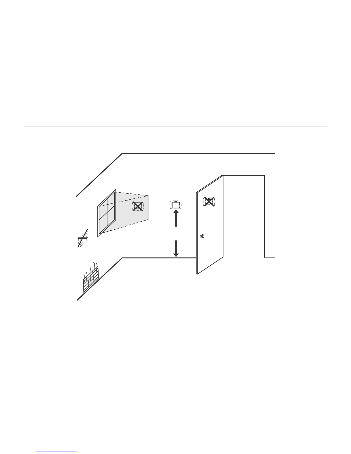
SelectingLocation
Install the thermostat about 5 ft. (1.5m) above the floor in an area with good air circulation at
average temperature. See Figure 5.
Do not install the thermostat where it can be affected by:
• Drafts or dead spots behind doors and in corners.
• Hot or cold air from ducts.
• Radiant heat from sun or appliances. Concealed pipes and chimneys.
• Unheated (uncooled) areas such as an outside wall behind the thermostat.
13
PS4000/PS5000 Touchscreen Programmable Thermostat
Figure 5. Selecting thermostat location.
14
5 FEET
(1.5 METERS)

PS4000/PS5000 Touchscreen Programmable Thermostat
InstallingWall Plate
CAUTION
Electrical Hazard.
Can cause electrical shock or equipment damage.
Disconnect power before wiring.
The thermostat can be mounted horizontally on the wall
1. Position and level the wall plate (for location only).
2. Use a pencil to mark the mounting holes.
3. Remove the wall plate from the wall and, if drywall, drill two holes in the wall, as marked.
For firmer material such as plaster, drill two holes. Gently tap anchors (provided) into the
drilled holes until flush with the wall.
4.
Position the wall plate over the holes, pulling wires through the wiring opening. See Figure 6
5. Insert the mounting screws into the holes and tighten.
15

PS4000/PS5000 Touchscreen Programmable Thermostat
Figure 6. Mounting wall plate.
16
WALL
WIRES THROUGH
WALL AND WIRE
SLOT
WALL ANCHORS
MOUNTING
HOLES(2)
MOUNTING
SCREWS(2)

PS4000/PS5000 Touchscreen Programmable Thermostat
WIRING (FIGURE 9-21)
All wiring must comply with local electrical codes and ordinances.
1. Select the set of terminal identifications (Table 1) that corresponds with system type
(conventional or heat pump in Figure 7).
2. Loosen the screws for the appropriate system type selected; see Table 1. See Table 2
for terminal designation descriptions. Insert wires in the terminal block under the loosened
screw. See Figure 8.
3. Securely tighten each screw.
PS4000 PS5000
4. Push excess wire back into the hole.
5. Plug the hole with nonflammable insulation to prevent drafts from affecting the thermostat.
6. See Figure 9 through 21 for t
ypical wiring hookups.
Figure 7. Selecting terminal identifications for system type.
17
S1 S2 C R RC E L Y2 Y G
S1 S2 C R RC W W2 Y2 Y G
O/B AUX
CONVENTIONAL
HEAT PUMP
SCREW
TERMINALS
S1 S2 C R RC L
S1 S2 C R RC W Y G
O/B
Y G

PS4000/PS5000 Touchscreen Programmable Thermostat
Table 1. Selecting Terminal Identifications for System Type.
System TypeModel
Wall Plate Terminal
Identifications
Wiring Diagram
Figures
Standard Heat/Cool Conventional
9, 10
lanoitnevnoCylnOtaeH
PS4000
PS5000
PS4000
PS5000
PS4000
PS5000
PS4000
PS5000
PS4000
PS5000
PS5000
PS4000
PS5000
PS5000
PS4000
PS5000
11
Heat Only with Fan Conventional
12
Hea
t
OnlyPowerto open and powe
r
to close zone valves
Conventional
13
Normall
y
Open Zone Valves Heat Onl
y
Conventional
14
lanoitnevnoCylnOlooC
15
Standard Multistage up to 3 Heat/2 Cool Conventional
16, 17
Heat Pump with No Auxiliary Heat Heat Pump
18, 19
Heat Pump with Auxiliary Heat Heat Pump
20, 21
18

PS4000/PS5000 Touchscreen Programmable Thermostat
IMPORTANT: Use 18 gauge thermostat wire.
Figure 8. Inserting wires in te
r
minal block.
19

PS4000/PS5000 Touchscreen Programmable Thermostat
Table 2. Terminal Designation Descriptions.
noitpircseDnoitangiseDlanimreTModel
RC (see Note 1)PS4000/PS5000
PS4000/PS5000
PS4000/PS5000
PS4000/PS5000
PS4000/PS5000
PS4000/PS5000
PS4000/PS5000
PS5000 only
PS5000 only
PS5000 only
PS5000 only
PS4000/PS5000
PS4000/PS5000
Powe
r
forcooling--connect to secondaryside ofcooling system
transforme
r
R (see Note 1)
Power for heating--connect to secondar
y
side ofheating system
transforme
r
C (see Note 2) Common wire from secondary side of cooling system transformer
yalertaeHW
osserpmoCY
r
contactor
naFG
r
elay
gniloocegatsdnoceS2Y
taehegatsdnoceS2W
r
ela
y
evlavrevoegnahC/ 3)etoNees(BO
for
heat pump systems
railixuAXUA
y
heatrelayforheat pump systems
smetsyspmuptaehrofyalertaehycnegremEE
otinomtnempiuqE)4etonees(L
rfor
heat pump systems
oodtuolanoitpO2S,1S
ror
indoo
r
r
emote sensor
20
NOTES:
1. When used in a single-transformer system, leave metal
j
umper wire in place between RC and
R. If used on a two-transformer system, remove metal
j
umper wire between RC and R.
2. Common wire is optional when thermostat is used with batteries.
3. I
f
thermostat is configured for a heat pump system in the Installer Set-up, configure
changeover valve for cool (O-factor
y
setting) or heat (B).
4. L terminal is an input (system monitor) when the System mode is in the HE
A
T, OFF, COOL or
A
UTO position. “L” terminal is a 24
V
A
C output when System mode is EmergencyHeat. When
using the “L” terminal, connect the 24
V
A
C Common. See LCD indications on page 90.
.

PS4000/PS5000 Touchscreen Programmable Thermostat
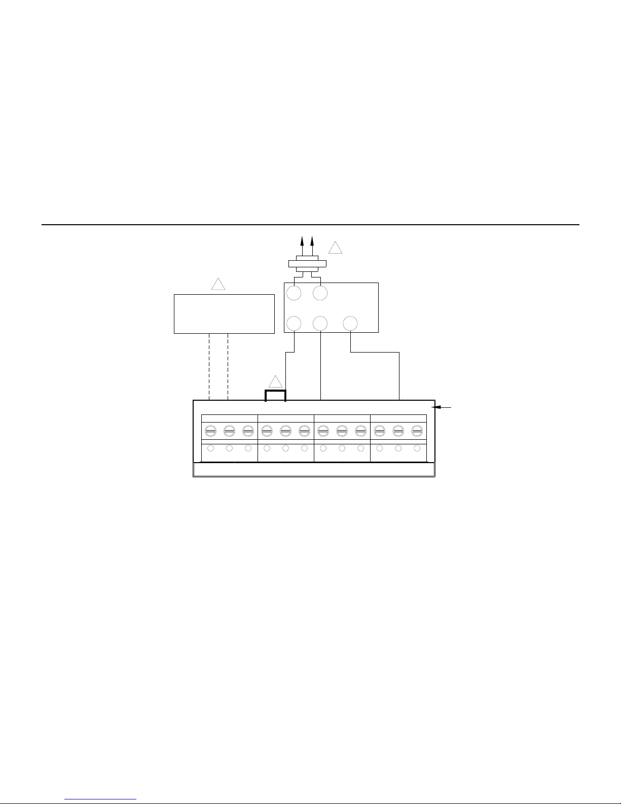
1. POWER SUPPLY. PROVIDE DISCONNECT MEANS AND OVERLOAD PROTECTION AS REQUIRED.
2. FACTORY INSTALLED JUMPER.
3. OPTIONAL OUTDOOR OR INDOOR REMOTE SENSOR. AVAILABLE ON SELECT MODELS. WIRES MUST HAVE A CABLE
SEPARATE FROM THE THERMOSTAT CABLE.
NOTE: Y2 IS ONLY ON THE PS5000.
Figure 9. Typical hookup of conventional single-stage heat and cool system with single
transfo
rmer
(1H/1C conventional).
21
CONVENTIONAL
S1 S2 C R RC W W2 Y2 Y G
OUTDOOR/INDOOR
TEMPERATURE
SENSOR
3
COMPRESSOR
CONTACTOR
OPTIONAL
24V AC
COMMON
CONNECTION
R C
1
2
FAN RELAY
HEAT RELAY

PS4000/PS5000 Touchscreen Programmable Thermostat
Figure 10. Typical hookup of conventional single-stage heat and cool system with two
transfo
r
mers (1H/1C conventional).
22
1. POWER SUPPLY. PROVIDE DISCONNECT MEANS AND OVERLOAD PROTECTION AS REQUIRED.
2. OPTIONAL OUTDOOR OR INDOOR REMOTE SENSOR. AVAILABLE ON SELECT MODELS. WIRES MUST HAVE A CABLE
SEPARATE FROM THE THERMOSTAT CABLE.
3. REMOVE FACTORY INSTALLED JUMPER.
NOTE: W2 AND Y2 ARE ONLY ON THE PS5000.
CONVENTIONAL
S1 S2 C R RC W W2 Y2 Y G
OUTDOOR/INDOOR
TEMPERATURE
SENSOR
2
R
C
1
FAN RELAY
HEAT RELAY
R
C
1
COMPRESSOR
CONTACTOR
OPTIONAL
24V AC
COMMON
CONNECTION
3

PS4000/PS5000 Touchscreen Programmable Thermostat
1. POWER SUPPLY. PROVIDE DISCONNECT MEANS AND OVERLOAD PROTECTION AS REQUIRED.
2. FACTORY INSTALLED JUMPER.
3. OPTIONAL OUTDOOR OR INDOOR REMOTE SENSOR. AVAILABLE ON SELECT MODELS. WIRES MUST HAVEACABLE
SEPARATE FROM THE THERMOSTAT CABLE.
NOTE: W2 AND Y2 ARE ONLY ON THE PS5000.
Figure 11. Typical hookup of heat-only system (1H conventional).
23
CONVENTIONAL
S1 S2 C R RC W W2 Y2 Y G
OUTDOOR/INDOOR
TEMPERATURE
SENSOR
3
HEAT RELAY
OPTIONAL
24V AC
COMMON
CONNECTION
C
R
1
2

PS4000/PS5000 Touchscreen Programmable Thermostat
1. POWER SUPPLY. PROVIDE DISCONNECT MEANS AND OVERLOAD PROTECTION AS REQUIRED.
2. FACTORY INSTALLED JUMPER.
3. OPTIONAL OUTDOOR OR INDOOR REMOTE SENSOR. AVAILABLE ON SELECT MODELS. WIRES MUST HAVEACABLE
SEPARATE FROM THE THERMOSTAT CABLE.
NOTE: W2 AND Y2 ARE ONLY ON THE PS5000.
Figure 12. Typical hookup of heat only system with fan (1H conventional).
24
CONVENTIONAL
S1 S2 C R RC W W2 Y2 Y G
OUTDOOR/INDOOR
TEMPERATURE
SENSOR
3
HEAT RELAY
OPTIONAL
24V AC
COMMON
CONNECTION
R
C
1
2
FAN RELAY
PS4000/PS5000 Touchscreen Programmable Thermostat
1. POWER SUPPLY. PROVIDE DISCONNECT MEANS AND OVERLOAD PROTECTION AS REQUIRED.
2. FACTORY INSTALLED JUMPER.
3. OPTIONAL OUTDOOR OR INDOOR REMOTE SENSOR. AVAILABLE ON SELECT MODELS. WIRES MUST HAVEACABLE
SEPARATE FROM THE THERMOSTAT CABLE.
NOTE: W2 AND Y2 ARE ONLY ON THE PS5000.
Figure 13. Typical hookup of heat only power to open and power to close zone valve system.
25
OUTDOOR/INDOOR
TEMPERATURE
SENSOR
3
R
C
1
2
W
B
R
TR
TR
MOTOR OR
VALVE
CONVENTIONAL
S1 S2 C R RC W W2 Y2 Y G

PS4000/PS5000 Touchscreen Programmable Thermostat
1. POWER SUPPLY. PROVIDE DISCONNECT MEANS AND OVERLOAD PROTECTION AS REQUIRED.
2. FACTORY INSTALLED JUMPER.
3. OPTIONAL OUTDOOR OR INDOOR REMOTE SENSOR. AVAILABLE ON SELECT MODELS. WIRES MUST HAVEACABLE
SEPARATE FROM THE THERMOSTAT CABLE.
NOTE: W2 AND Y2 ARE ONLY ON THE PS5000.
Figure 14. Typical hookup ofheat only system with normally open zone valves.
26
CONVENTIONAL
S1 S2 C R RC W W2 Y2 Y G
OUTDOOR/INDOOR
TEMPERATURE
SENSOR
3
NORMALLY OPEN
ZONE VALVE
OPTIONAL
24V AC
COMMON
CONNECTION
R
C
1
2

PS4000/PS5000 Touchscreen Programmable Thermostat
1. POWER SUPPLY. PROVIDE DISCONNECT MEANS AND OVERLOAD PROTECTION AS REQUIRED.
2. FACTORY INSTALLED JUMPER.
3. OPTIONAL OUTDOOR OR INDOOR REMOTE SENSOR. AVAILABLE ON SELECT MODELS. WIRES MUST HAVEACABLE
SEPARATE FROM THE THERMOSTAT CABLE.
NOTE: W2 AND Y2 ARE ONLY ON THE PS5000.
Figure 15. Typical hookup of cool only system (1C conventional).
27
CONVENTIONAL
S1 S2 C R RC W W2 Y2 Y G
OUTDOOR/INDOOR
TEMPERATURE
SENSOR
3
COMPRESSOR
CONTACTOR
OPTIONAL
24V AC
COMMON
CONNECTION
R
C
1
2
FAN RELAY

PS4000/PS5000 Touchscreen Programmable Thermostat
Figure 16. Typical hookup of conventional multi-stage two-stage heating and two-stage
cooling in a single-t
r
ansformer system (2H/2C, 2H/1C or1H/2C conventional).
28
1. POWER SUPPLY. PROVIDE DISCONNECT MEANS AND OVERLOAD PROTECTION AS REQUIRED.
PS5000 ONLY.
2. FACTORY INSTALLED JUMPER.
3. OPTIONAL OUTDOOR OR INDOOR REMOTE SENSOR. AVAILABLE ON SELECT MODELS. WIRES MUST HAVEACABLE
SEPARATE FROM THE THERMOSTAT CABLE.
CONVENTIONAL
S1 S2 C R RC W W2 Y2 Y G
OUTDOOR/INDOOR
TEMPERATURE
SENSOR
3
FAN RELAY
HEAT RELAY 1
HEAT RELAY 2
COOL RELAY 2
COOL RELAY 1
R
C
1
2
 Loading...