

Page 1

User Instructions
This booklet contains important information concerning the proper and safe operation of your new amplifier.
MT-Series
MT-1000/2000II
Made in Taiwan
Profe ssion al Power Amp lif iers
Index
02 Important Precautions
Introduction02
03 Front Panels
04 Rear Panels
05 Set Up
07 Operating Modes
08 Protection
08 Features
09 Specifications
UNiKA
PROTECT
CLIP
SIGNAL
PROTECT
CLIP
SIGNAL
CHANNEL 1 CHANNEL 2
MIN
MAX
MIN
MAX
MT-1000
CLIP
SIGNAL
CHANNEL 1 CHANNEL 2
MIN
MAX
MIN
MAX
PROFESSIONAL STEREO AMPLIFIER
MT-2000II
PROTECT PROTECT CLIP
SIGNAL
UNiKA
Page 2

UNiKA MT-1000/MT-2000II
pag e 1
This symbol is intended to alert the user to the presence of
non insulated "dangerous voltage" within the product's
enclosure that may be of sufficient magnitude to constitute
a risk of electric shock to persons.
!
CAUTION: Risk of the electrical shock - DO NOT OPEN!
CAUTION: To reduce the risk of electrical shock, do not remove cover. No user serviceable parts inside. Refer all servicing
to qualified service personnel.
WARNING: To prevent electrical shock or fire hazard, do not expose this amplifier to rain or moisture. Before using this
amplifier read the user manual for further warnings.
This symbol is intended to alert the user of
the presence of important operating and
maintenance (servicing) instructions in the
literature accompanying the product.
Este símbolo tiene el propósito de alertar al usuario de la
presencia de “voltaje peligroso” que no tiene aislamiento
dentro de la caja del producto que puede tener una
magnitud sufciente como para constituir riesgo de corrientazo.
!
PRECAUCIÓN: Riesgo del choque eléctrico - NO SE ABRA
PRECAUCIÓN: Para disminuir el riesgo de choque eléctrico, no quite la cubierta. No hay piezas adentro que el usario puede
reparar. Deje todo mantenimiento al los técnicos cualifcados.
ADVERTENCIA: Para prevenir choque eléctrico o riesgo de incendios, no deja expuesto a la lluvia o a la humedad este amplif
cador. Antes de usar este amplif cador, lea mas advertencias en la guia de operacion.
Este símbolo tiene el propósito de alertar al
usuario de la presencia de instrucciones
importantes sobre la operación y
mantenimiento en la literatura que vienc con el producto.
Ce symbole est utilisé pur indiquer à l’utilisateur la présence
à l'intérieur de ce produit de tension non-isolée
dangereuse pouvant être d'intensité suffisante pour
constituer un risque de choc électrique.
!
ATTENTION: Risque de choc électrique - NE PAS OUVRIR!
ATTENTION: Afin de réduire le risque de choc électrique, ne pas enlever le couvercle. Il ne se trouve à l’intérieur aucune piéce
pouvant être réparée par l'utilisateur. Confier l'entretien à un personnel qualifé.
AVERTISSEMENT: Afin de prévenir les risque de décharge ou de feu, n’exposez pas cet appareil à la pluie ou à l’humidité.
Avant d’utiliser cet amplificateur, lisez les avertissements supplémentaries situés dans le guide.
Ce symbole est utilisé pour indiquer à l’utilisateur
qu'il trouvera d'importantes instructions
importantes sur l'utilisation et l'entretien de
l'appareil dans la littérature accompagnant le produit.
Dieses Symobl soll den Anwender vor unisollierten
gefährlichen Spannungen innerhalb des Gehäuses warnen,
die von Ausreichender Stärke sind, um einen elektrischen
Schlag verursachen zu können.
!
VORSICHT: Risiko - Elektrischer Schlag! Nicht öffnen!
VORSICHT: Um ddas Risiko eines elektrischen Schlages zu vermeiden, nicht die Abdeckung enfernen. Es befinden sich keine
Teile darin, die vom Anwender repariert werden könnten. Reparaturen nur von qualifzierte Fachpersonal
durchführen lassen.
ACHTUNG: Um einen elektrischen Schlag oder Feuergefahr zu vermeiden, sollte diesen Gerät nicht dem Regen oder
Feuchtigkeit ausgesetz werden. Vor Inbetriebnahme unbedingt die Bedienungsanleitung lesen.
Dieses Symobl soll den Benutzer auf wichtige
Instruktionen in der Bedienungsanleitung
aufmerksam machen, die Handhabung und
Wartung des Produkts betreffen.
CAUTION
Do not open -
risk of electric shock
CAUTION: TO REDUCE THE RISK OF ELECTRIC SHOCK, DO
NOT REMOVE THE COVER. THERE ARE NO USER
SERVICEABLE PARTS INSIDE. REFER ALL SERVICE TO
YOUR AUTHORIZED DEALER.
The l ightn ing fla sh with a n arrow t riang ular
sym bol is in tende d to aler t the use r to the
pre sence o f non ins ulate d “dang erous
vol tage” w ithin t he prod ucts en closu re, and
may b e of suff ici ent magni tud e to co nsti tut e
a ris k of elec tric sh ock.
The e xclam ation p oint tr iangu lar sym bol is
int ended t o alert t he user t o the pre sence o f
imp ortan t opera ting an d maint enanc e
(se rvici ng) ins truct ions in t he user m anual
acc ompan ying th e ampli fier.
!
!
FOR O PTIMU M PERFO RMANC E AN D RELIA BILIT Y
DO NO T PRESE NT THE AMPL IFIER W ITH A
SPE AKER LO AD OF LES S THAN 2 OH MS OR ANY
COM BINATI ON OF SPE AKER S T HAT TOGET HER ARE L ESS
THA N 2 OHMS!
USI NG ONE SP EAKER , IT MUST BE R ATED AT 4 OR MORE
OHM S. USIN G TWO SPE AKER S, THEY MU ST RATED E ACH AT 4
OR MO RE OHMS .
USI NG THRE E SPEAK ERS, THE Y MUST BE R AT ED EAC H AT 8
OR MO RE OHMS .
POU R AS SURER L A F IABI LETE ET O BTEN IT UNE
PER FORMA NCE OPT IMALE , NESOU METTE
JAM AIS L’AM PLIFI CATEUR A UNE C HARGE
D’I MPEDA NCE
TOTAL E INFER IEURE A 2 OHM S, NI AVEC UN H .P. N EN
COM BINAI SON DES H .P.
AVEC U N H.P., IL FAUT UN E CHARG E D’IMP EDANC E MINIM UM
DE 2 OH MS.
AVEC D EUX H.P., FAU T POUR CH AOUN UN E CHARG E
D’I MPEDA NCE MIN IMUM DE 4 O HMS.
AVEC TR OIS H.P., FA UT POUR C HAOUN U NE CHUR GE
D’I MPEDA NCE MIN IMUM DE 8 O HMS.
!
!
Page 3

pag e 2
IMPORTANT PRECAUTIONS
To reduc e the r isk o f electric al sh ock or fire, d o not e xpo se this unit r ain o r
moist ure .
Do not s pil l wat er or other li qui ds into or on to y our u nit .
Do not a tte mpt t o operate th is un it if the powe r cor d has b een frayed o r
broke n.
Do not a tte mpt t o remove or br eak o ff th e gro und prong fr om th e electric al
cord. This p ron g is us ed to reduce t he ri sk of e lectr ica l sho ck and f re in
case of a n int ern al shor t.
Disc onn ect m ain power be for e making any t ype o f con necti on.
Do not r emo ve th e cover unde r any c ondition s. There a re no u ser
servi cea ble p arts in sid e.
Neve r plu g thi s unit in to a dim mer p ack.
Alwa ys be s ure t o mount this u nit i n an area that w ill a llo w prope r
venti lat ion . Allow ab out 6 ” (15 cm) betwee n thi s dev ice and a w all .
Do not a tte mpt t o operate th is un it, if it beco mes d ama ged.
This u nit i s int ended for in doo r use only, use of this pro duc t outdoors v oid s
all war ran tie s.
Duri ng lo ng pe riods of non -us e, disconn ect t he un it’s main power.
Alwa ys mo unt t his unit in a sa fe an d stable man ner.
Powe r cor ds sh ould be rout ed so t hey are not li kel y to be w alked o n,
pinch ed by i tem s place d upo n or ag ainst them .
Clea nin g -Th e outside of t he un it should be w ipe d own w ith a sof t clo th an d
mild cl ean er wh en need ed.
Heat - The a mpl ifier shou ld be s ituated aw ay fr om he at sources s uch a s
radia tor s, he at regi ste rs, s toves, or ot her a ppl iance s (in clu ding ampli fie rs)
that pr odu ce he at.
The fi xtu re sh ould be serv ice d by qualifi ed se rvi ce pers onn el wh en:
A. Th e power -su ppl y cord or the pl ug ha s bee n damag ed.
B. Obje cts h ave f allen , or li qui d has been spi lle d int o the uni t.
C. Th e appli anc e has b een expose d to ra in or w ater.
D. Th e fixtu re do es no t appear to op era te no rmall y or ex hib its a
marke d cha nge i n perfo rma nce .
Congr atu lat ions an d tha nk yo u for purcha sin g MT-1 000/M T-20 00I I
ampli fie r. The se am plifiers a re re pre senta tio n of UN iKA’s con tin uing
commi tme nt to p roduc e the b est a nd highest q ual ity a udio pr odu cts a t an
aff ordab le pr ice . The se am plifi ers a re de signed to pr ovi de a bi g impac t in
sound r epr odu ction . Ple ase r ead and unde rst and t his man ual c omp letely
befor e att emp ting to o per ate y our new ampl ifi er. Th is bo oklet cont ain s
impor tan t inf ormat ion c onc erning the p rop er an d safe op era tio n of your new
ampli fie r.
UNPACKIN G: E ver y MT-1000/M T-20 00I I ampli fie r has b een thorou ghl y
teste d and h as be en ship ped i n per fect opera tin g con ditio n. Ca ref ully check
the shi ppi ng ca rton fo r dam age t hat may have o ccu rre d durin g shi ppi ng. If
the car ton a ppe ars to be d ama ged , carefull y ins pec t your un it fo r any
damag e and b e sur e all acc ess ori es necessa ry to o per ate the s yst em ha ve
arriv ed in tac t. In the e ven t dam age has been f oun d or pa rts are m iss ing ,
pleas e con tac t your de ale r for f urther ins tru cti ons.
INSTALLATION: Th ese a mplifier s are d esi gned to m oun t int o a
stand ard 1 9”r ack. The front pa nel p rov ides fo ur ho les u sed to screw t he un it
into a ra ck. T he un it al so provide s a way t o rea r mount t he un it in to a rack for
added s ecu rit y. Rea r mounting t he un it is e speci all y rec ommended i f the
unit is t o mou nte d into a mo bil e rac k.
INTRODUCTION
Important Precautions Introduction Front Panels Rear Panels Set Up Operating Modes Protection Features Specifications
UNiKA MT-1000/MT-2000II
Page 4

MT-1000/2000II FRONT PANEL
1. Rack Moun tin g Ear s - Two fr ont p ane l mou nti ng ho les a re pr ovided on each
mounting e ar.
2. Fan Inlet Gril ls an d Fil ter - M T Series a mpl ifi ers a re co ole d by on e sin gle r ear -
mounted fa n. Co ol ai r fro m fro nt gr ill s is fi lte red a nd flows over the heat sin ks
and exhaus ts to b ack s ide . Mak e sur e the se ou tle ts re main clear to allow
unrestri cte d air f low.
3. Channel 1 S ign al In dic ato r - Thi s gre en LE D wil l glo w whe n there is an input of
the audio si gna l int o cha nne l one .
4. Channel 1 C lip I ndi cat or - Th e red c lip L ED wi ll be gin t o fla sh when the channel
begins to ov erl oad . At thi s poi nt th e cha nne l wil l beg in to distort. Under h eav y
clipping a cti vit y, lower the cha nne l's g ain c ont rol t o red uce t he ri sk of d amage to
your speak ers a nd am pli fie r. Thi s LED m ay gl ow wh en th e uni t has b een t urn ed
off , thi s is no rmal.
5. Channel 1 P rot ect I ndi cat or - Th e red p rot ect L ED wi ll be gin to glow when the
channel go es in to pr ote ct mo de. W hen t he ch ann el go es into protect mode , all
output for t he ch ann el wi ll tu rn of f. This is to protect any s pea ker s con nec ted t o
the channe l.
6. Channel 1 G ain C ont rol - T his r ota ry kn ob is u sed t o con tro l the output signal of
channel on e. Tun ing t he kn ob in c loc kwi se di rec tio n will increase sign al ou tpu t.
7. AC P owe r Swi tch - M T-10 00I I amp lif ier has a front-pane l AC mai ns po wer
switch.
8. Power Ind ica tor - T his L ED wi ll gl ow wh en ma ins p owe r is applied to the unit .
This light m ay co nti nue t o glo w bri efl y aft er ma ins p ower has been turned o ff,
this is norm al.
9. Channel 2 G ain C ont rol - T his r ota ry kn ob is u sed t o con tro l the output signal of
channel tw o. Tun ing t he kn ob in c loc kwi se di rec tio n will increase sign al ou tpu t.
10. Channe l 2 Pro tec t Ind ica tor - T he re d pro tec t LED w ill b egin to glow when the
channel go es in to pr ote ct mo de. W hen t he ch ann el go es into protect mode , all
output for t he ch ann el wi ll tu rn of f. This is to protect any s pea ker s con nec ted t o
the channe l.
11. Channel 2 C lip I ndi cat or - Th e red c lip L ED wi ll be gin t o fla sh when the
channel be gin s to ov erl oad . At thi s poi nt th e cha nne l will begin to distor t.
Under heav y cli ppi ng ac tiv ity, l owe r the c han nel 's ga in co ntr ol to r edu ce the
risk of dama ge to y our s pea ker s and a mpl ifi er. Th is LE D may g low w hen t he
unit has bee n tur ned o ff, this is nor mal .
12. Channe l 2 Sig nal I ndi cat or - Th is gr een L ED wi ll gl ow wh en there is an input
of the audio s ign al in to ch ann el tw o.
pag e 3
Figure 2
Figure 1
Important Precautions Introduction Rear Panels Set Up Operating Modes Protection Features Specifications Front Panels
UNiKA MT-1000/MT-2000II
PROTECT
CLIP
SIGNAL
PROTECT
CLIP
SIGNAL
CHANNEL 1 CHANNEL 2
MIN
MAX
MIN
MAX
MT-1000
CLIP
SIGNAL
CHANNEL 1 CHANNEL 2
MIN
MAX
MIN
MAX
PROFESSIONAL ST EREO AMPLIFIER
MT-2000 II
PROTECT PROTECT CLIP
SIGNAL
UNiKA
1 2
3
6
4
5
7
8
9
12
11
10
12
1 2
3
6
4
7
8
9
12
11
12
5 10
Page 5

13. Coolin g Vent s - The se ve nts a re us ed fo r pro per c ool ing . Never block these
vents when i nst all ing t he am pli fie r or ot her a sso ciated equipment a nd ke ep
them clean a t all t ime s. Air m ust f low u nim ped ed th rou gh these ports.
14. Channe l 1-2 B ala nce d 1/4 ” TRS & X LR In put C onn ect ors - T hese connectors
accept inp ut si gna ls on b ala nce d TRS a nd XL R inp ut pl ugs . Con nec tor s for
each chann el ar e in pa ral lel , the u nus ed co nne cto rs may be used for “loop
through” c onn ect ion t o oth er am pli fie rs.
TRS pin sett ing : Tip/ sig nal p osi tiv e, Ri ng/ sig nal negative, Slee ve/ gro und .
XLR pin sett ing : Pin -2/ sig nal p osi tiv e, Pi n-3 /signal negative , Pin -1/ gro und .
For MT-2000 II, i t als o all ows t o use E uro blo ck in put c onnectors. Eurob loc k pin
setting: ( +): s ign al po sit ive - H ot, ( -): s ign al ne gative – Cold; ( ): ground
15. Amp. M ode S ele cti on Sw itc h - Thi s switch allows the am pli fie r ope rat ing m ode
from eithe r ste reo o r mon o bri dge s ele cti on. Am pli fiers are factory- con fig ure d
for Stereo M ode . See s ect ion o n Mod e Sel ect ion f or mo re information.
16. Fan Outl et Po rts - M T series equi ppe d wit h one s ing le 2- spe ed co oli ng fa n.
Cooling ai r ent ers t he am pli fie r thr oug h the f ron t grills and exhaust s thr oug h the
fan. Be sure n ot to b loc k the se po rts w hen i nst all ing t he amplifier or othe r
associat ed eq uip men t. Air m ust f low u nim ped ed th rough these ports.
17. Fuse Hol der - T his h old er ho use s the e xte rna l fus e. Alw ays replace wit h the
exact same t ype f use , oth erw ise i nst ruc ted t o do so b y an au thorized audi o
service te chn ici an.
18. A/C Po wer I npu t - IEC AC p owe r inl et co nnector, plug this ca ble i n to a
standard 110 V or 220V wall outlet. B e sur e tha t sup pli ed vo lta ge ma tch es th at
of the requi red v olt age o f you r amp lif ier. N eve r plu g your amplifier in to a w all
outlet tha t doe s not m atc h the r equ ire d vol tag e of yo ur amplifier, serio us
damage may o ccu r to yo ur un it.
19. Ground L ift S wit ch (M T-10 00 on ly) - T his s wit ch is u sed t o disconnect the
internal g rou nd si gna l fro m the a mpl ifi er' s cha ssis ground. Thi s may r educe
the buzz tha t is ca use d fro m an el ect ric al 50 Hz/ 60H z cycle.
20. Channe l 1-2 O utp ut Ja ck / 5- way B ind ing P ost - C onn ect t o your speakers
input jack . Red i s pos iti ve si gna l and B lac k is ne gat ive signal.
MT-1000/2000II REAR PANEL
pag e 4
Important Precautions Introduction Front Panels Set Up Operating Modes Protection Features Specifications Rear Panels
UNiKA MT-1000/MT-2000II
Figure 4
Figure 3
Balanced Balanced
CAUTION
RISK OF ELECTRIC SHOCK
DO NOT OPEN
CAUTION: REPLACE WITH SAME TYPE FUSE AND RATING
120V-, 60Hz, 840VA
T250V, 7A, L
17 181514 16 201913 13
Balanced Balanced
STEREO
AMP MODE
BRIDGE
CH 1 INPUT CH 2 CH 1
_ _
+ +
CH 2 INPUT
CAUTION
RISK OF ELECTRIC SHOCK
DO NOT OPEN
ATTENTION: RISQUE DE CHOC ELECTRIQUE - NE PAS OUVRIR
CAUTION: REPLACE WITH SAME TYPE FUSE AND RATING
120VAC
60Hz
1200VA
FUSE
T250V
10A L
CH 2
BRIDGE
4 Ohms/Ch
Minimum
Stereo Mode
8 Ohms
Minimum
Bridge Mode
CH 1
_
_
_
+
+
+
WARNING: TO REDUCE THE RISK OF FIRE OR ELECTRIC
SHOCK DO NOT EXPOSE TO RAIN OR MOISTURE
16 2014 15 17 1813 13
Page 6
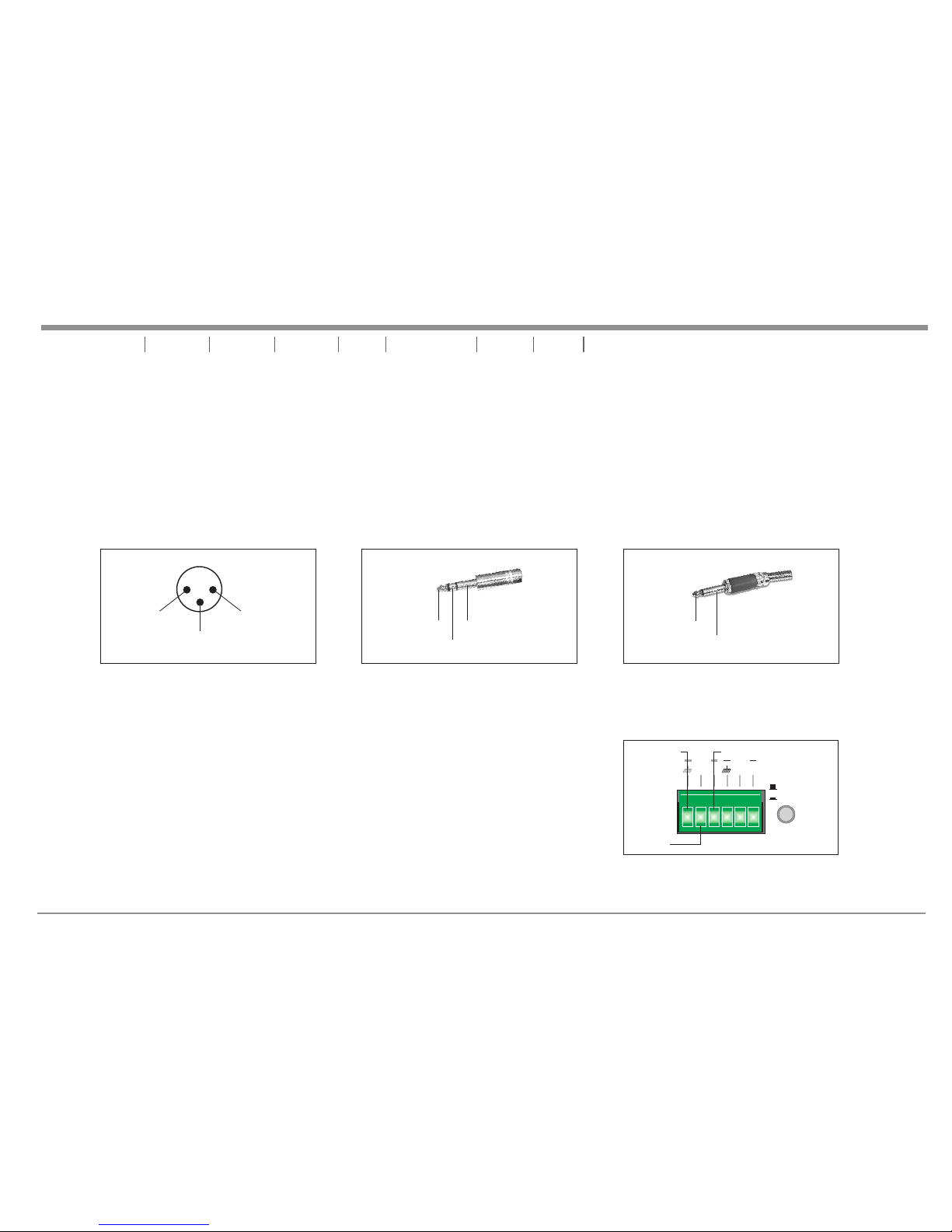
INPUTS - The MT-100 0 and MT-2 000 II ampl ifi ers all ow you to use tw o types o f inp ut conn ect ors per c hannel, a XL R femal e jac k for bal anc ed
conne ctions and a 1 /4” TRS fema le ja ck that w ill accept b alanc ed an d unbal anc ed conn ectors. Us e these c onn ectio ns to c onnec t the output
signa l from a mixer, c ross- ove r or EQ to th e MT-1 000 and M T-2000II am plifi ers . A bala nce d conne ction is rec ommen ded f or cabl e run s longe r
than 20 ft. When con struc tin g your ow n XLR c ables f ollow the pi n confi gur ation d esc ribed b elow for pro per con nec tions . For c able ru ns shorter
than 20 ft., you may c hoose t he 1/ 4” TS u nbala nced input o ption . The 1 /4” T S unb alanc ed in put opt ion may be mor e conve nie nt for mo st us ers
due to th e abundant s upply o f pre fabri cat ed cabl es availab le at you r loc al audi o dealer. In ad ditio n, fo r the MT-2 000 II also h as an option o f
Eurob lock input c onnec tor s for use rs to u se.
BINDI NG POST/BA NANA PLU G: Conn ect y our spe akers to the b indin g pos t outpu ts on t he
rear of t he amplifi er. Th e speak er wi re may be c onnected b y bare wi re (d irect ly co nnect ed,
usual ly for perma nent co nne ction s), b anana p lug, or spad e conne cto r. Conne ctions are m ade
to chan nel one and ch annel t wo ou tputs f or St ereo Mo de or across t he red te rmi nals of c han nel
one and c hannel two f or Mono B rid ge Mode .
IMPOR TANT N OTICE: Alth ough a sp eak er will o perate wit h the positi ve and ne gat ive lea ds
plugg ed into eith er term ina l on the am pli fier bi nding p ost , be sure t o plu g the neg ati ve lead i nto
the bla ck termina l and pos iti ve lead i nto t he red te rminal. En surin g pro per pol ari ty will a void
speak ers being ou t of phas e tha t can cau se a lo ss of bas s response .
2 Hot (+data)
1
3
2
Male XLR Pin Configuration
Figure 5
1 Ground / Return / 0v
3 Negative (-data)
Balanced TRS 1/4” Plug
Hot (+)
Negative (-)
Ground/Shield
Figure 6
Unbalanced TS 1/4” Plug
Hot (+)
Negative (-)
Figure 7
pag e 5
SET UP
Important Precautions Introduction Front Panels Rear Panels Operating Modes Protection Features Specifications Set Up
OUTPUTS -
UNiKA MT-1000/MT-2000II
Euroblock Input Connector
Figure 8
STEREO
AMP MODE
BRIDGE
CH 2 CH 1
_ _
+ +
Cold
Hot
Ground
Page 7

pag e 6
Important Precautions Introduction Front Panels Rear Panels Operating Modes Protection Features Specifications Set Up
UNiKA MT-1000/MT-2000II
BANAN A PLUG: (F igure 9 )
When co nnecting y our spe ake rs to the a mpl ifier u sing banan a plugs , be su re that t he re d and bla ck caps on
the bin ding post ar e compl ete ly scre wed i n. Inse rt the banan a plugs i nto t he caps o f the b indin g post, be sur e
that th e banana plu gs are in ser ted sec ure ly to avo id the risk of p oppin g out .
BARE WI RE CONNECT ION: (F igu re 10)
When co nnecting y our spe ake rs to the a mpl ifier u sing bare wi re, uns cre w the red a nd bl ack cap s on the
bindi ng post, be su re not to c omp letel y rem ove or un screw the re d and bla ck ca ps. Str ip ba ck the wi re
insul ation 1/2” ( 13mm) . Ins ert the b are w ire int o the hole tha t was rev eal ed by uns cre wing th e binding po st
cap. Aft er inserti ng the wi re in to the bi ndi ng post h ole, screw t he bind ing p ost cap d own o n the wir e. To
reduc e the risk of sh ock or da mag e to your a mpl ifier, b e sure that th e wire co nne cted to o ne bi nding p ost
does no t come in cont act wit h tha t of anot her.
SPADE CONNE CTO R: (Fig ure 11 )
When co nnecting y our spe ake rs to the a mpl ifier u sing spade c onnec tor, u nscre w the r ed and bl ack caps on
the bin ding post, b e sure no t to co mplet ely r emove o r unscrew th e red and b lac k caps. I nse rt the sp ade
conne ctor into th e bindi ng po st and ti ght en the ca ps down on the s pade co nne ctor. To reduce t he risk of
shock o r damage to yo ur ampl ifi er, be sur e tha t the wir e connecte d to one bi ndi ng post d oes n ot come i n
conta ct with that o f anoth er.
MONO BR IDGE CONNE CTION S: (F igure 1 2)
Mono br idge opera tion co nne ction s will follo w the abo ve de scrip tio ns, how ever, when op erati ng in m ono
bridg e operatio nthe sp eak er conn ections wi ll run be twe en the tw o pos itive ( red) leads , Use channe l two
posit ive output t ermin al fo r the neg ati ve conn ection and t he chan nel o ne posi tiv e outpu t terminal f or the
posit ive connec tion.
Typical speaker output using bare wire.
Insert bare wire into the binding post and tighten.
Typical speaker output using spade connectors.
Insert bare wire into the binding post and tighten.
Figure 11
1/5 "
13m m
Figure 10
Figure 9
Figure 12
Page 8

pag e 7
Figure 13 Typical Stereo Output Connections
SPEAKERS
4 OHM MINIMUM
SPEAKERS
4 OHM MINIMUM
OPERATING MODES
STEREO OPERATION : Page 7 / Figure 13 details an example of a typical stereo set-up. Connect your inputs into channels one and two of the amplifier.
Connect your speakers to the outputs on the rear of the amplifier. Be sure that your front gain controls are turned down to their lowest level (fully counterclockwise). Turn your amplifier on. Turn your input source level up. Use your front gain controls to regulate the output volume. Be sure not to raise the volume to
the clip level, however an intermittent clip signal is acceptable.
MONO BRIDGE OPERATION : Page 7 / Figure 14 details a mono bridge set-up. Be sure your amplifier and all other audio equipment are powered down.
Press the Stereo/Mono Bridge switch to the Mono Bridge position. Connect an input signal to channel one. Connect your speaker across the red output binding
post on the rear of your amplifier. Turn your equipment on (your amplifier should always be the last item you turn on). Apply an input source signal to your
amplifier. Use the channel one gain control to regulate your amplifier output.
Important Precautions Introduction Front Panels Rear Panels Set Up Protection Features Specifications Operating Modes
UNiKA MT-1000/MT-2000II
Balanced Balanced
STEREO
AMP MODE
BRIDGE
CH 1 INPUT CH 2 CH 1
_ _
+ +
CH 2 INPUT
CAUTION
RISK OF ELECTRIC SHOCK
DO NOT OPEN
ATTENTION: RISQUE DE CHOC ELECTRIQUE - NE PAS OUVRIR
CAUTION: REPLACE WITH SAME TYPE FUSE AND RATING
120VAC
60Hz
1200VA
FUSE
T250V
10A L
CH 2
BRIDGE
4 Ohms/Ch
Minimum
Stereo Mode
8 Ohms
Minimum
Bridge Mode
CH 1
_
_
_
+
+
+
WARNING: TO REDUCE THE RISK OF FIRE OR ELECTRIC
SHOCK DO NOT EXPOSE TO RAIN OR MOISTURE
CH-1 Input
CH-2 Input
MT-2000II
REAR PANEL
STEREO
AMP MODE
BRIDGE
SPEAKERS
8 OHM MINIMUM
Balanced Balanced
STEREO
AMP MODE
BRIDGE
CH 1 INPUT CH 2 CH 1
_ _
+ +
CH 2 INPUT
CAUTION
RISK OF ELECTRIC SHOCK
DO NOT OPEN
ATTENTION: RISQUE DE CHOC ELECTRIQUE - NE PAS OUVRIR
CAUTION: REPLACE WITH SAME TYPE FUSE AND RATING
120VAC
60Hz
1200VA
FUSE
T250V
10A L
CH 2
BRIDGE
4 Ohms/Ch
Minimum
Stereo Mode
8 Ohms
Minimum
Bridge Mode
CH 1
_
_
_
+
+
+
WARNING: TO REDUCE THE RISK OF FIRE OR ELECTRIC
SHOCK DO NOT EXPOSE TO RAIN OR MOISTURE
CH-1 Input
Only
MT-2000II
REAR PANEL
STEREO
AMP MODE
BRIDGE
Figure 14 Typical Mono Bridge Set-Up
Page 9
pag e 8
Important Precautions Introduction Front Panels Rear Panels Set Up Operating Modes Specifications Protection Features
PROTECTION
SAFE POWER LEVELS AT DIFFERENT OUTPUT LOADS:
8-Ohm Loads: The amplifier can operate at its rated power level without risk of overheating. However, it may caused excessive temperature if it is pushed hard enough
to continually light the “CLIP” indicator, the amplifier's average output power can reach its maximum peak.
4-Ohm Loads: If the “CLIP” indicator flashes occasionally, the amplifier is approaching its Maximum long-term power capacity. If it is lit about half the time, the amplifier
channel will probably go into thermal protection within a few minutes.
2-Ohm Loads: Do not recommend to use MT Series for 2ohm loads.
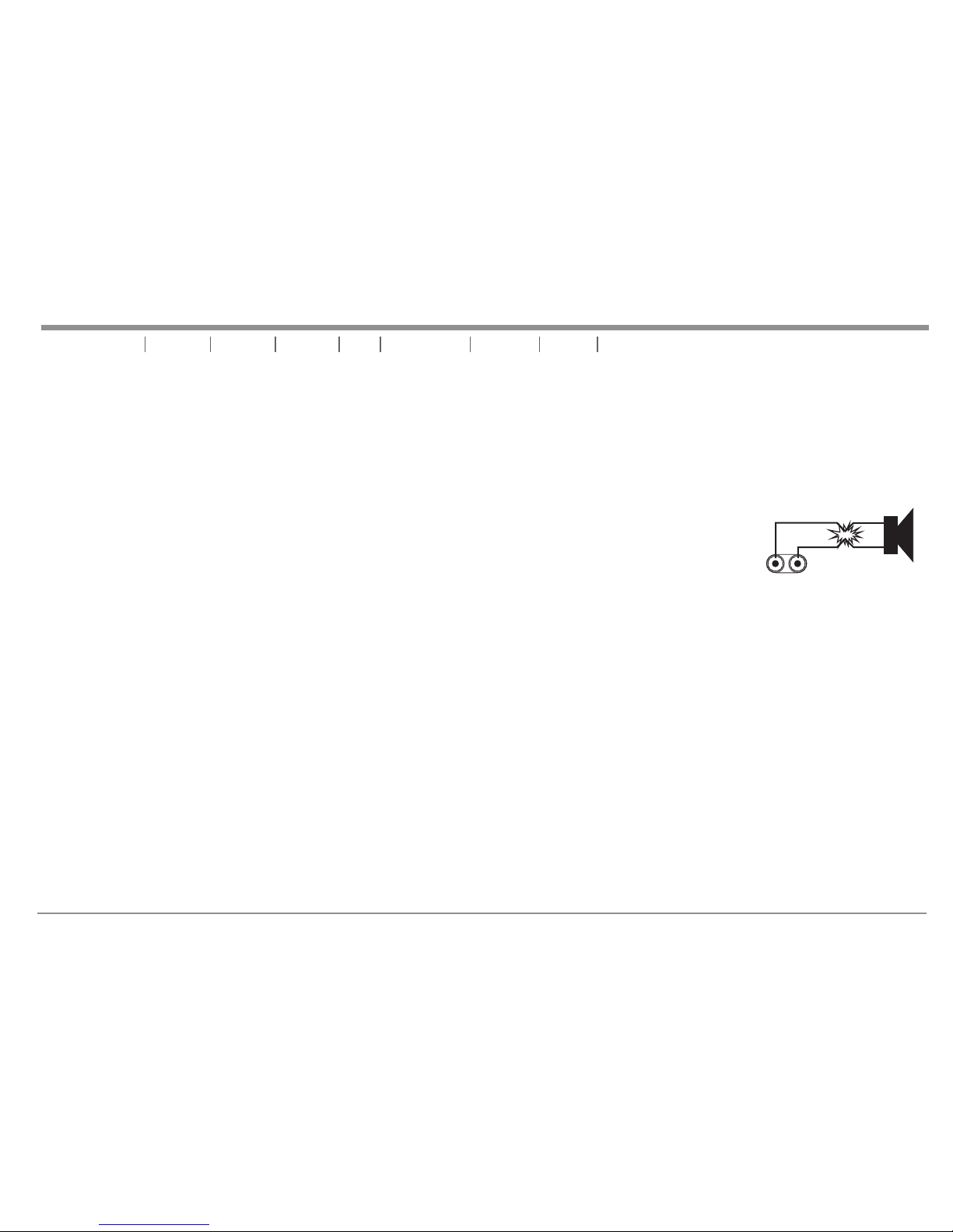
SHORT CIRCUIT PROTECTION - The MT Series amplifier comes with built-in Output Short Circuit Protects. The Output Short
Circuit Protection protects the output devices of the amplifier from short circuits and stressful loads. If your speaker lines shorted, the
amplifier automatically detects this problem and discontinued operation for that channel. If one side of your amplifier becomes shorted
and goes into protect mode, the other side will continue to operate normally. During short circuit protection, the “CLIP” LED and
“PROTECT” LED will light simultaneously indicating amplifier fault. Channel output during the “Short Circuit Protection” will be
interrupted (i.e. no sound output). Short Circuit Protection can usually be traced back to the signal output line (i.e. speaker line). Check
the line from the output terminal of the amplifier to the speaker. If this line is good, check the internal speaker connections and
components. A short circuit will usually be traced to a bad cable or a bad speaker component and is rarely traced to the amplifier itself.
THERMAL PROTECTION - A single variable speed fan on the MT Series amplifier provide adequate cooling. During low level output the fans run at normal
speeds. During high output and as heat raises, (exceeding 50°C.), the fans will run at higher speeds to aid the cooling process. If the heatsink temperature exceeds
91°C., the amplifier will mute until the amplifier cools down. When the amplifier cools below 90°C., the amplifier will return to normal operations. Be sure not to operate
your amplifier below the minimum load ratings to reduce the risk of overheating problems.
UNiKA MT-1000/MT-2000II
INPUT/OUTPUT PROTECTION - The input circuits are isolated by resistors. An ultrasonic network uncouples RF from the output and helps to keep the amplifier
stable with reactive loads.
OPERATING VOLTAGE (AC MAINS) - On the rear panel will indicate the correct AC mains voltage. Connecting to the wrong voltage is dangerous and may
damage the amplifier. Always be sure the source voltage for your areas matches the required voltage for your amplifier.
GAIN CONTROLS - The gain controls are located on the front panel and are calibrated in 2dB of attenuation from full gain. It is best to adjust the amplifier so no
“hissing” is heard from speakers with no music being played, this will ensure the lowest possible distortion during normal operation.
AMPLIFIER FEATURES
GROUND LIFT SWITCH (MT-1000 only) - Applying or lifting the ground switch will change level for background noise and hum, if the noise level remains the
same in either position, better to keep the ground lift switch in the ground position. This will eliminate 50Hz/60Hz cycle hum that is sometimes induced when mounting
several units in the same rack.
LED INDICATORS: Each channel has three LEDs. One green LED indicates signal, one red LED indicates signal clipping and one red LED indicates protections
mode for shorts/overload. Both channels also share the center blue LED that indicates the mains power is applied to the unit.
Page 10

Important Precautions Introduction Front Panels Rear Panels Set Up Operating Modes Protection Features Specifications
pag e 9
SPECIFICATIONS
UNiKA MT-1000/MT-2000II
Frequency Response (20Hz~20KHz)
R.M.S. Output Power 2 Ch Driven
4ohms/8ohms 1KHz 1% THD
R.M.S. Output Power Bridged Mono
8ohms 1KHz 1% THD
Input Sensitivity
Total Harmonic Distortion
Crosstalk @ 1KHz
Damping Factor
Output Circuitry
Cooling System
Dimensions (H×W×D)
Weight
Rack Space
Power Consumption
@ Maximum Output Power 8ohms
Signal To Noise Ratio
below rated power 20Hz to 20kHz,
A-Weighted
M T- 1000
4ohm s 150W
8ohm s 100W
1V
±0.2dB
<0.03%
>65dB
>250
288W
4.61A@110V
CLASS AB
Single 2-Speed Fan
44 x 483 x 240 mm
5.2kg
1U
300W
>100dB
M T- 2000II
CLASS AB
Single 2-Speed Fan
44 x 483 x 345 mm
9kg
1U
4ohm s 300W
8ohm s 200W
600W
1V
±0.2dB
<0.04%
>65dB
>250
506W
5.6A@110V
>100dB
Page 11

pag e 10
Important Precautions Introduction Front Panels Rear Panels Set Up Operating Modes Protection Features Specifications
UNiKA MT-1000/MT-2000II
Page 12

Pro fes sio nal Po wer Am pli f ie rs
UNiK A
 Loading...