

Page 1

UNiKA
P R O F E S S I O N A L A U D I O
MX-880
UNiKA
POWER
INPUT LEVEL
-24 -12
-20
MAIN INPUT LEVEL
dB
SPLITTER
0
dB
0 +6
+15
+9-6
+12
MAIN LINK
OUT
IN
OUTPUT LEVEL
0 +6
-24 -12
0
-20
+15
dB
MIXER
MAIN OUTPUT LEVEL
( )
E
S
I
T
( )
dB
-24 -24 -24 -24 -24 -24
SPLITTER
+9-6
MIXER
+12
SPLIT/MIX
( )
INPUT OUTPUT LEVEL
dB
-18 -18 -18 -18 -18 -18
-6 -6 -6 -6 -6 -60 0 0 0 0 0+6 +6 +6 +6 +6 +6
+18 +18 +18 +18 +18 +18
-12 -12 -12 -12 -12 -12
+12 +12 +12 +12 +12 +12
0
+9-6
-20
+12
+15
dB
LEVEL
LEFT
BALANCE/PAN
SPLITTER
MIXER
RIGHT
SPLIT/MIX
INPUT OUTPUT LEVEL
0
-20
+15
dB
LEVEL
( )
dB
+9-6
+12
LEFT
BALANCE/PAN
( )
INPUT OUTPUT LEVEL
dB
0
SPLITTER
RIGHT
SPLIT/MIX
+9-6
MIXER
-20
+12
+15
dB
LEVEL
LEFT
BALANCE/PAN
SPLITTER
MIXER
RIGHT
SPLIT/MIX
INPUT OUTPUT LEVEL
0
-20
+15
dB
LEVEL
( )
dB
+9-6
+12
LEFT
BALANCE/PAN
INPUT OUTPUT LEVEL
0
SPLITTER
MIXER
-20
RIGHT
SPLIT/MIX
LEVEL
dB
R
N
+9-6
+12
+15
( )
dB
LEFT
BALANCE/PAN
( )
INPUT OUTPUT LEVEL
dB
+9-6
+12
+15
LEFT
BALANCE/PAN
654321
RIGHT
MX-880
PRO 8-CH ANNEL
SPLITTER / MIXER
0
SPLITTER
MIXER
-20
RIGHT
∞∞∞∞∞∞∞∞
dB
SPLIT/MIX
LEVEL
R
C
T
U S E R
I N S T R U C T I O N S
S
U
O
I
N
ii
ii
This booklet contains important information concerning the proper and safe operation of your new amplifier.
S
Page 2

UNiKA MX-880 SAFETY INSTRUCTIONS
Http://w ww/ uni ka. com.tw
CAUTION
RISK OF ELECTRIC SHOCK
DO NOT OPEN
CAUTION: To reduce the risk of electrical shock, do
not remove the cover (or back). No user
serviceable parts inside; refer servicing to
qualified personnel.
WARNING: To reduce the risk of fire or electrical
shock, do not expose this appliance to rain
or moisture.
!
!
This symbol, w herever it appear s, alerts
you to the prese nce of uninsulate d
dangerous vo ltage inside the en closu re voltage that m ay be suffic ient to constitut e
a risk of shock.
This symbol, w herever it appear s, alerts
you to importa nt operating and
maintenanc e instructions in t he
accompanyi ng literature. Re ad the
manual.
DETAILED SAFETY INSTRUCTIONS:
All the safety and operation instructions should be read before the appliance is operated.
Retain Instructions: The safety and operating instructions should be retained for future reference.
Heed Warnings: All warnings on the appliance and in the operating instructions should be adhered to.
Follow instructions: All operation and user instructions should be followed.
Water and Moisture: The appliance should not be used near water (e.g. near a bathtub, washbowl,
kitchen sink, laundry tub, in a wet basement, or near a swimming pool etc.).
Ventilation: The applian ce shou ld be situated so that its loc ation or position does not int erfere with its
proper ventilation. For example, the appliance should not be situa ted on a bed, sofa rug, or simil ar
surface that may block the ven tilatio n open ings, or pla ced in a built-in installation, such as a bookcase or
cabinet that may impede the flow of air through the ventilation openings.
Heat: The appliance should b e situated aw ay from heat sources such as radiators, heat registers, stoves,
or other appliance (including amplifiers) that produce heat.
Power Source: The appliance should b e connected to a power supply only of the type described in the
operating instructions or as marked on the appliance.
Grounding or P olariza tion: Precautions should be taken so that the g roundin g or polarization me ans of
an appliance is not defeated.
Power-Cord Pr otectio n: Power supply cords should be routed so that they are not li kely to be walked on
or pi nched by it ems placed upon or against them, payi ng particular atte ntion to co rds and plugs,
convenience receptacles and the point where they exit from the appliance.
Cleaning: The appliance should be cleaned only as recommended by the manufacturer.
Non-use Periods: The power cord of the ap pliance should be unpl ugged from the outlet when left unuse d
for a long period of time.
Object a nd Liquid Entr y: Care should be tak en so t hat objects do not fa ll and liquids are not spilled into
the enclosure through openings.
Damage Requiring Service: The appliance should be serviced by qualified service personnel when:
The power supply cord or the plug has been damaged; or
Objects have fallen, or liquid has been spilled into the appliance; or
The appliance has been exposed to rain; or
The appliance does not appear to operate normally or exhibits a marked change in performance; or
The appliance has been dropped, or the enclosure damaged.
Servicing: The user should n ot at tempt to service the a ppliance beyond that is described in the
Operating Instructions. All other servicing should be referred to qualified service personnel.
Page 3

UNiKA MX-880
Http://w ww/ uni ka. com.tw
Ultra-flexible, multi-purpose 8-channel Signal Router for stage and studio applications
UNiKA
POWER
( )
INPUT LEVEL
0 +6
-24 -12
0
-20
+15
dB
SPLITTER
MAIN INPUT LEVEL
dB
+9-6
OUT
IN
+12
MAIN LINK
MAIN OUTPUT LEVEL
OUTPUT LEVEL
-24 -12
-20
MIXER
( )
dB
0 +6
0
SPLITTER
+9-6
MIXER
+12
+15
dB
SPLIT/MIX
( )
INPUT OUTPUT LEVEL
dB
-18 -18 -18 -18 -18 -18
-6 -6 -6 -6 -6 -60 0 0 0 0 0+6 +6 +6 +6 +6 +6
-24 -24 -24 -24 -24 -24
-20
+18 +18 +18 +18 +18 +18
-12 -12 -12 -12 -12 -12
+12 +12 +12 +12 +12 +12
LEVEL
0
+9-6
+15
dB
+12
LEFT
BALANCE/PAN
SPLITTER
MIXER
RIGHT
SPLIT/MIX
INPUT OUTPUT LEVEL
0
-20
dB
LEVEL
+9-6
+12
+15
BALANCE/PAN
( )
dB
SPLITTER
MIXER
RIGHT
LEFT
SPLIT/MIX
INPUT OUTPUT LEVEL
0
-20
+15
dB
LEVEL
( )
dB
+9-6
+12
LEFT
BALANCE/PAN
( )
INPUT OUTPUT LEVEL
dB
0
SPLITTER
+9-6
MIXER
-20
+12
+15
RIGHT
SPLIT/MIX
LEVEL
RIGHT
LEFT
dB
BALANCE/PAN
SPLIT/MIX
SPLITTER
MIXER
INPUT OUTPUT LEVEL
0
-20
+15
dB
LEVEL
( )
dB
+9-6
+12
LEFT
BALANCE/PAN
( )
INPUT OUTPUT LEVEL
dB
654321
0
SPLITTER
+9-6
MIXER
-20
+12
+15
RIGHT
∞∞∞∞∞∞∞∞
SPLIT/MIX
LEVEL
RIGHT
LEFT
dB
BALANCE/PAN
Use it as Effects Mixer, for P.A. Monitoring, Live Sound Systems, Theaters, Conference
Rooms, Hotels, Churches, etc.
Any channel can be selected either as Mixer or Splitter
Can be used as 8-IN, 2-OUT Line Mixer
Can be used as 2-IN, 8-OUT Line Splitter
Can be used as 2-IN, 8-OUT Line Splitter
Can be used as independent line driver to convert -10 dBV into +4 dBu or vice versa
Extremely high headroom-offering more dynamic range
MX-880
PRO 8-CHA NNEL
SPLITTER / MIXER
Ultra-wide bandwidth from 2 Hz to 200 kHz for “open” sound
The MX-880 offers 6 mono inputs, 6 mono outputs, 2 main inputs and 2 main outputs
A Main Link switch allows you to route the Main Input to the Main Output to link several units
Accurate 4/8-segment LED metering for each individual gain section
Servo-balanced XLR and 1/4" TRS inputs and outputs
Completely versatile DI-Box due to servo-balanced inputs and outputs
Ultra low-noise operational amplifiers for outstanding sound performance
High-quality detented potentiometers and illuminated switches
-1-
Page 4

1
UNiKA MX-880
Http://w ww/ uni ka. com.tw
Introduction Co n t rol el e m e nts Block Diagram Applications Spec if ications
1.INTRODUCTION
The MX-880 is designed to meet highest requirements:
professional recording, broadcast and television studios,
CD and digital production facilities, etc. Much like an allin-one tool, it provides virtually unlimited configurations.
Be it the distribution of a stereo signal to several outputs
(splitter); the combination of separate signals to one
stereo output (mixer), or the specific level adaption of
individual signals.
Basically, the unit consists of six mono channels, which can
be used either as a splitter or as a mixer. For instance, a
stereo program source can be inserted via the main input to
be subsequently routed to any of the mono channels that are
set to SPLIT mode. Using the individual BALANCE/PAN
control, you can - for each channel - determine the ratio
between the left and right main input signals that are routed
to the corresponding output of the channels. Thus, the
stereo input signal coming from the main input section can
be distributed selectively among the six mono output
channels.
In MIX mode, the input signals from the respective
channel(s) can be mixed at the stereo main output, with the
individual BALANCE/PAN control determining the signal ratio
between the left and right main outputs (pan function). It is of
particular advantage that, in MIX mode, the stereo input
signal from the main input section is alternatively routed to
the main outputs. By using this feature a total of up to 8
single signals can be combined.
In MIX mode, the mono input signals are simultaneously
applied to the respective mono outputs, which permits each
channel to be used as an individual matching amplifier. The
LEVEL controls in the corresponding channels enable the
user to adapt the levels at will, with a maximum gain of +15
dB. Levels used in home-
converted into studio levels (+4 dBu), and vice versa.
recording can therefore be
high operating levels. Externally induced mains hum etc. will
be effectively suppressed. The automatic servo-function
recognizes the presence of unbalanced connectors and
adjusts the nominal level internally to avoid level differences
between the input and output signals (correction 6 dB).
1.3 Rack mounting
The Unika MX-880 fits into one standard 19" rack unit of
space (1 3/4"). Please allow at least an additional 4" depth
for the connectors on the back panel. Be sure that there is
enough air space around the unit for cooling and please do
not place the MX-880 on high temperature devices such as
power amplifiers etc. to avoid overheating.
1.4 Mains voltage
The Unika MX-880 is equipped with Universal Mains
Voltage Switch Mode Power Supply.
1.5 Audio connections
The audio inputs and outputs on the Unika MX-880 are fully
balanced. If possible, connect the unit to other devices in a
balanced configuration to allow for maximum interference
immunity.
Unbalanced use of
mono 1/4" jack plugs
Tip=
Signal
Sleeve=
Ground/Shield
Balanced use of
stereo 1/4" jack plugs
Tip=
hot(+ve)
Ring=
cold(-ve)
Sleeve=
Ground/Shield
1.1 Typical applications
The MX-880 is one of the most flexible systems of its type.
The following applications can be realized:
2 IN/8 OUT splitter, 8 IN/2 OUT mixer, 6 IN/6 OUT matching
amplifier or any other combination.
Keyboard submixer
Distribution amplifier for P.A. systems, discotheques,
theatres, churches, hotels, communication systems, etc.
Add-on module for mixer channels
Add-on module for effect and monitor paths
Level translator from -10 dBV to +4 dBu etc.
1.2 Balanced inputs and outputs
As standard, the Unika MX-880 is installed with electronically
servo-balanced inputs and outputs. The new circuit design
features automatic hum and noise reduction for balanced
signals and thus allows for trouble-free operation, even at
Tip
Sleeve
Strain relief clamp
For connection of balanced and unbalanced plugs, ring and
sleeve have to be bridged at the stereo plug.
Strain relief clamp
Tip
Ring
Sleeve
Balanced use with XLR connectors
Input Output
1=Ground/Shield
12
3
For unbalanced use pin1 and pin3 have to be bridged
2=hot(+ve)
3=cold(-ve)
Fig. 1.5: Different plug types
1 2
-2-
3
Page 5

2
UNiKA MX-880
Introduction Block Di agram Applicat io ns Specifica ti ons Co n tr o l el e me n ts
2.CONTROL ELEMENTS
Http://w ww/ uni ka. com.tw
UNiKA
POWER
( )
INPUT LEVEL
0 +6
-24 -12
0
-20
+15
dB
SPLITTER
MAIN INPUT LEVEL
dB
+9-6
OUT
IN
+12
MAIN LINK
MAIN OUTPUT LEVEL
OUTPUT LEVEL
-24 -12
-20
MIXER
( )
dB
0 +6
0
SPLITTER
+9-6
MIXER
+12
+15
dB
SPLIT/MIX
( )
INPUT OUTPUT LEVEL
dB
-18 -18 -18 -18 -18 -18
-6 -6 -6 -6 -6 -60 0 0 0 0 0+6 +6 +6 +6 +6 +6
-24 -24 -24 -24 -24 -24
-20
+18 +18 +18 +18 +18 +18
-12 -12 -12 -12 -12 -12
+12 +12 +12 +12 +12 +12
LEVEL
0
+9-6
+15
dB
+12
LEFT
BALANCE/PAN
SPLITTER
MIXER
RIGHT
SPLIT/MIX
INPUT OUTPUT LEVEL
0
-20
dB
LEVEL
+9-6
+12
+15
BALANCE/PAN
( )
dB
SPLITTER
MIXER
RIGHT
LEFT
SPLIT/MIX
INPUT OUTPUT LEVEL
0
-20
+15
dB
LEVEL
( )
dB
+9-6
+12
LEFT
BALANCE/PAN
( )
INPUT OUTPUT LEVEL
dB
0
SPLITTER
+9-6
MIXER
-20
+12
+15
RIGHT
SPLIT/MIX
LEVEL
RIGHT
LEFT
dB
BALANCE/PAN
SPLIT/MIX
SPLITTER
MIXER
INPUT OUTPUT LEVEL
0
-20
+15
dB
LEVEL
( )
dB
+9-6
+12
LEFT
BALANCE/PAN
( )
INPUT OUTPUT LEVEL
dB
0
SPLITTER
+9-6
MIXER
-20
+12
+15
RIGHT
∞∞∞∞∞∞∞∞
SPLIT/MIX
LEVEL
RIGHT
LEFT
dB
BALANCE/PAN
Fig. 2: MX-880 front panel
The Unika MX-880 has six identical channels. Each channel is equipped with two rotary controls, one button and eight LEDs.
Moreover there is a main section with two rotary controls, one button and eight LEDs.
2.1 The front panel control elements
2 5 8
INPUT LEVEL
-24 -12
( )
0 +6
dB
0
+9-6
-20
SPLITTER
MAIN INPUT LEVEL
+12
+15
dB
MAIN LINK
OUTPUT LEVEL
-24 -12
OUT
IN
-20
MAIN OUTPUT LEVEL
0
dB
MIXER
( )
0 +6
+15
dB
INPUT OUTPUT LEVEL
-18
-24
-12
-6 0 +6
( )
dB
+12
+18
1
0
SPLITTER
+9-6
MIXER
SPLIT/MIX
-20
∞∞∞
+12
dB
LEVEL
+9-6
+12
+15
BALANCE/PAN
LEFT
RIGHT
654321
MX-880
PRO 8-CHA NNEL
SPLITTER / MIXER
1 3 4 6 7 9
Fig. 2.1: Control elements on the fron panel
1.The MAIN INPUT LEVEL control sets the main input gain, before the signal reaches the input bus. In SPLIT mode, the MAIN
INPUT LEVEL control determines the common output level for all mono outputs.
2.The 4-digit INPUT LEVEL meter informs you about the input level of the main input within a range from -24 to +6 dB.
3.By depressing the MAIN LINK switch you can route the MAIN INPUT signal to the MAIN OUT. This way it is possible to route a
maximum of eight input channels to the main mix.
4.The MAIN OUTPUT LEVEL control adjusts the output level applied to the main outputs. The levels present at the six mono outputs
are not affected. Summing the signal levels of several mono channels can overload the main output stage. The MAIN OUTPUT
LEVEL control is therefore used to adjust the overall output level.
5.The 4-digit OUTPUT LEVEL meter informs you about the output level of the main input within a range from -24 to +6 dB.
6.This SPLIT/MIX switch sets the respective channel to SPLITTER or MIXER mode.
7.The LEVEL control determines the signal level of the individual channels. In SPLIT mode, the LEVEL control sets the output level of
the mono channels. In MIX mode, however, it controls the amount of the mono channel's input signal feeding into the main output
section; at the same time, the level of the mono channel can be determined, which-owing to the maximum gain of +15 dB - allows
for converting, e.g., home recording levels (-10 dBV) into studio levels (+4 dBu).
8.The 8-digit OUTPUT LEVEL meter informs you about the output level of each channel within a range from -24 to +18 dB.
9.With the BALANCE/PAN control you can set the balance between the left and right main signals. In SPLIT mode, the main input
signal is routed to the mono output, with the BALANCE control determining the balance between the left and right main signal
portions. In MIX mode, the mono inputs are mixed and routed via the LEVEL control to the main outputs, with the PAN controls
determining the allocation of the mono inputs to the left and right main outputs.
-3-
Page 6

2
UNiKA MX-880
Introduction Block Di agram Applicat io ns Specifica ti ons Co n tr o l el e me n ts
2.2 The rear panel control elements
Serial No.:
CH 6 OUT CH 6 IN CH 5 OUT CH 5 IN
CH 4 OUT MAIN OUT R MAIN IN RCH 4 IN MAIN OUT L MAIN IN L
1110 12 13 14 15 16
Fig. 2.2: Rear panel elements
10.MONO OUTPUTS (channel 5 to 6).
These are the mono outputs, available as balanced phone jacks.
11.MONO INPUTS (channel 5 to 6).
These are the mono inputs. Connection takes place via balanced phone jacks.
12.MONO OUTPUTS (channel 1 to 4).
These are the mono outputs, available as balanced XLR connectors.
Http://w ww/ uni ka. com.tw
AC INPUT
50/60Hz
T1.6A
Fuse
250V
13.MONO INPUTS (channel 1 to 4).
These are the mono inputs. Connection takes place via balanced XLR connectors.
14.MAIN OUTPUTS.
These are the main outputs, available as balanced XLR connectors. They may be fed either by the left and right main
inputs or by any of the six mono inputs (or a combination of both).
15.MAIN INPUTS.
These are the main audio inputs of your MX-880, available as balanced XLR connectors. They may feed the mono outputs
of all channels which are operated in SPLIT mode.
16.MAINS CONNECTION.
Use the enclosed power cord to connect the unit to the mains.
-4-
Page 7

3
UNiKA MX-880
Introduction Application s Sp ec ifications Contr o l e lemen t s Block Diagram
3.BLOCK DIAGRAM
Http://w ww/ uni ka. com.tw
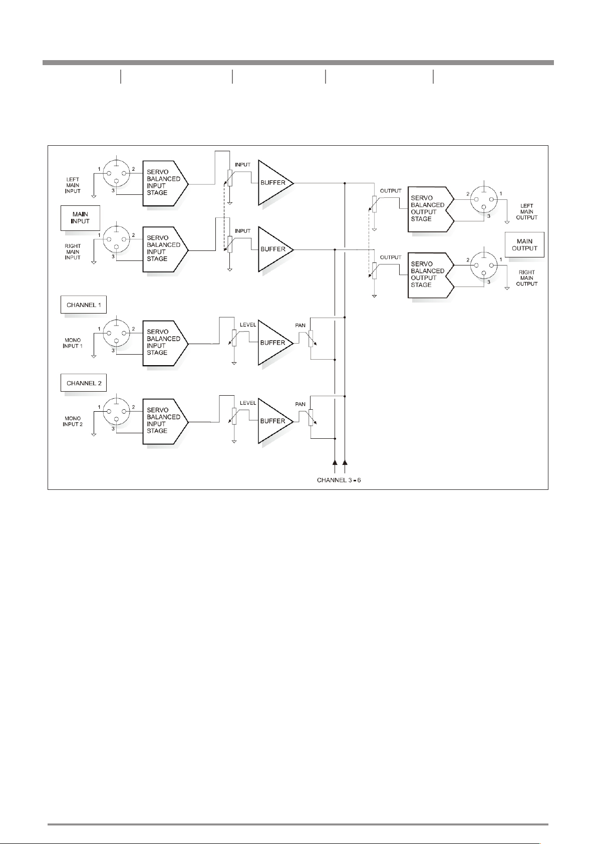
Fig. 3.1: Block diagram of the Unika MX-880
MAIN Section
Both main inputs interface via the MAIN INPUT LEVEL control with the input bus as well as with the main outputs.
The MAIN OUTPUT LEVEL control determines the output level of the signals which are summed by the second
bus (i.e., the output bus) and are subsequently routed to the main outputs.
SPLIT Mode
In SPLIT mode, the main input signal is sent via the BALANCE control to the output buffer amplifiers of the mono
channels, with the LEVEL control determining the output level of the respective channel. The maximum gain is +15 dB.
MIX Mode
In MIX mode, the input signals of the mono channels are “collected” via the LEVEL and PAN controls and are
routed to the output bus. In this mode, the LEVEL control determines the amount of each channel at the output
bus, while the PAN control is responsible for the allocation of the input signal to the left and right main outputs.
Additionally, the input signal is routed to the respective mono outputs, i.e., the circuit acts as a matching amplifier.
The LEVEL control allows for level compensation of up to +15 dB.
-5-
Page 8
4
UNiKA MX-880
Introduction Block D iagram Spec if ications Contr o l e lemen t s Applications
4.APPLICATION
4.1 Application as a mixer
Http://w ww/ uni ka. com.tw
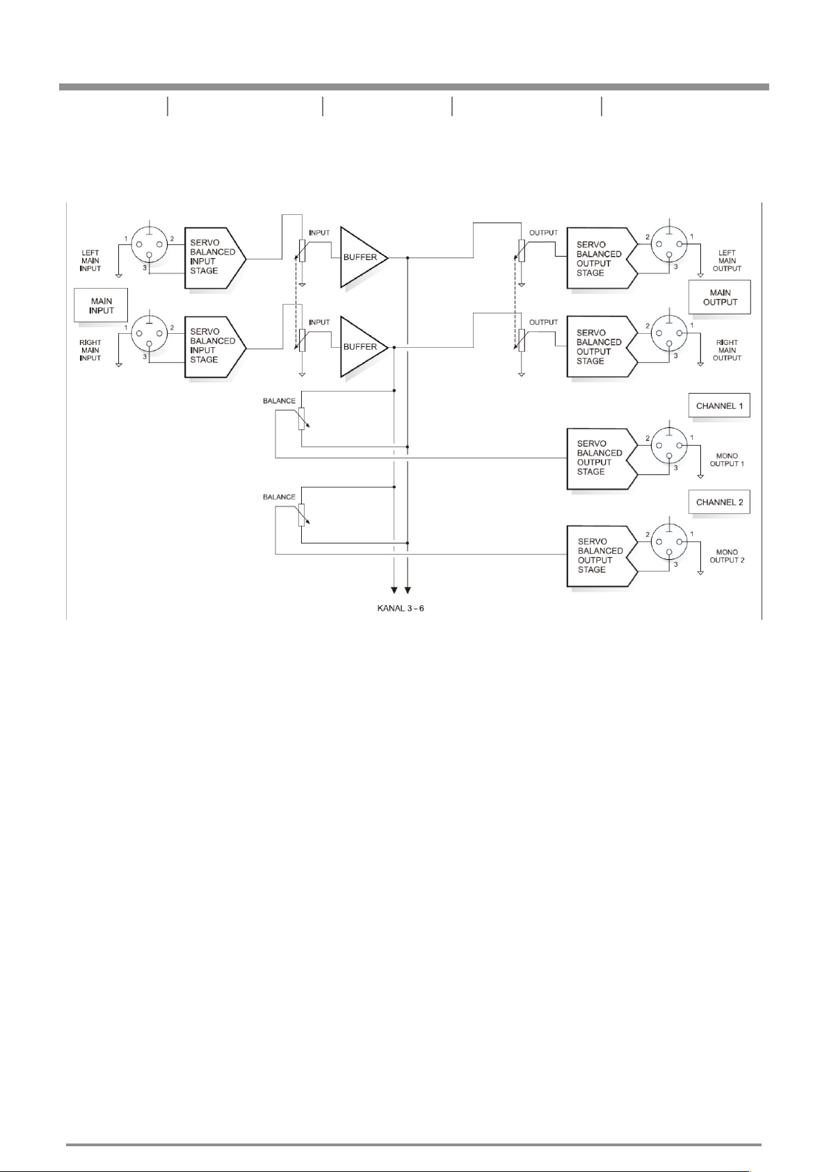
Fig. 4.1: Block diagram of the Mixer function
When the mono channels are operated in MIX mode, a maximum of 8 (6+2) mono input signals can be summed
and routed to the main outputs. In this mode, the individual signal sources are connected to the mono inputs on
the UNIKA MX-880. Each channel has a LEVEL knob to control the amount of its signal relative to others in the
main section. Via the corresponding PAN control, each mono input signal can be routed either to the left or right
main output. Of course, any intermediate pan settings can be achieved as well. The MAIN OUTPUT LEVEL
control determines the overall level of the main output signal.
Since the two main inputs are alternatively routeable to the main outputs, two additional input signals can be
added using the main inputs. For this you have to depress the MAIN LINK switch. However, as these inputs do
not feature a PAN control, the left main input will always be routed to the left main output; similarly, the right main
input can only be sent to the right main output. A total of 8 mono channels can thus be routed to two main
outputs.
-6-
Page 9
4
UNiKA MX-880
Introduction Block D iagram Spec if ications Contr o l e lemen t s Applications
4.2 Application as a spliter
Http://w ww/ uni ka. com.tw
Fig. 4.2: Block diagram of the SPLITTER function
A splitter is a distribution amplifier which allows for splitting a specific input signal to several outputs. This
function is of use, e.g., in a large-scale sound reinforcement system where the mixer's output signal needs to be
allocated to several power amplifiers. Another field of application is in tape duplication systems, where one
master tape machine is to be interfaced with several tape duplication recorders.
In this mode, the output signal from the mixer is applied to the main inputs of the UNIKA MX-880. If the
SPLIT/MIX switches are set to “SPLIT”, the mono outputs of the respective channels provide either the left or the
right main signal. Depending on the setting of the BALANCE control, any balance between left and right main
signal can be adjusted.
At the same time, the main input signal is also sent to the left or right main output, so that here two additional splitter
outputs are available. Please note that these outputs do not feature a balance routing function. The left main input is
routed exclusively to the left main output; similarly, the right main input feeds the right main output only.
4.2.1 The MX-880 as a 4-channel stereo splitter
For this special application, the splitter function configures the unit as a 4-channel stereo splitter. Here, the
stereo signal source is connected to the two main inputs. If all mono channels are operated in SPLIT mode, the
BALANCE controls of channels 1, 3, and 5 are set to “LEFT”, and the BALANCE controls of channels 2, 4, and 6
to “RIGHT”: thus, the corresponding stereo output pairs are routed through channels 1+2, 3+4, and 5+6. This
kind of application is particularly useful for tape duplication systems.
-7-
Page 10
4
UNiKA MX-880
Introduction Block D iagram Spec if ications Contr o l e lemen t s Applications
4.3 Application as a matching amplifier
Http://w ww/ uni ka. com.tw
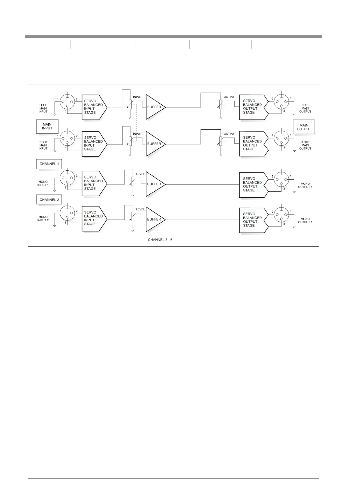
Fig. 4.3: Bloc k diagram of the MATCHING A MPLIFIER functi on
The Unika MX-880 can also be used as a multiple matching amplifier. The task of a matching amplifier is to
convert the level of a signal source into another level. For instance, a CDR or MD recorder with home recording
level (-10 dBV) can be raised to studio level (+4 dBu). Of course, this process can also be reversed (level
attenuation).
In this application, the MX-880 is operated in MIX mode. The output of the signal source is connected to the
mono input of the MX-880. The corresponding mono output provides the resulting output signal which can be
raised or lowered in level. Each of the six mono channels is equipped with a LEVEL control. The control range is
from -oo (full attenuation) to a maximum gain of +15 dB.
-8-
Page 11

5
UNiKA MX-880
Http://w ww/ uni ka. com.tw
Introduction Block D iagram Application s Contr o l e lemen t s Specifications
5.SPECIFICATIONS
AUDIO INPUTS
Connectors
Type
Impedance
Nominal oper ating level
Max. input lev el
CMRR
AUDIO OUTPUTS
Connectors
Type
Impedance
Max. output le vel
SYSTEM SPECIFICATIONS
Frequency re sponse
S/N ratio
THD
XLR and 1/4" TRS
RF filtered, s ervo-balanced i nput
50 kOhms balan ced, 25 kOhms unbal anced
-10 dBV to +4 dBu
+21 dBu balanc ed and unbalanced
Typ. 40 dB, > 55 dB @ 1 kHz
XLR and 1/4" TRS
Electronic ally servo-bala nced ou tput stage
60 Ohms balanc ed, 30 Ohms unbalan ced
+22 dBu balanc ed and unbalanced
5 Hz to 200 kHz, +/- 3 d B
>95 dBu, unwei ghted, 22 Hz to 22 kHz
0.002 % typ. @ +4 dB u, 1kHz, gain 1
FUNCTION CONTROLS
Main input lev el
Main ouput lev el
Level
Balance/pa n
FUNCTION SWITCHES
Main Link
Split/mix
INDICATORS
Input level (m ain)
Ouput level (m ain)
Input/outp ut level
POWER SUPPLY
Mains Voltage s
Power Consum ption
Fuse
Mains Connec tion
variable
variable
variable for e ach channel
placing in the s tereo field
links the main i nput signal to the ma in outp ut
changeover f rom split to mix mode f or each channel
4-digit LED di splay: -24/-12/ 0/+6 dB
4-digit LED di splay: -24/-12/ 0/+6 dB
8-digit LED di splay: -24/-18/ -12/-6/0/+6/+ 12/+1 8 dB
Universal Mains Voltage
90V to 240Vac
Max. 35Watts
100 - 120 V ~: T 630 mA H
Standard IEC receptacle
45Hz to 65Hz
200 - 240 V ~: T 315 m A H
PHYSICAL/WEIGHT
Dimensions ( H * W * D)
Net Weight
Shipping Weight
approx. 1 3/4" ( 44.5 mm) * 19" (482.6 m m) * 8 1/2" (217 mm)
approx. 3 kg
approx. 3.8 kg
-9-
Page 12

UNiKA
P R O F E S S I O N A L A U D I O
 Loading...