

Page 1

User Instructions
This booklet contains important information concerning the proper and safe operation of your new amplifier..
MP-Series
MP-2800 / MP-4000 / MP-5000
Made in Taiwan
Profe ssion al Power Amp lif iers
Index
02 Introduction
03 Front Panel
04 Rear Panel
05 Set Up
07 Speakon Assembly
08 Operating Modes
12 Protection
13 Features
14 Specifications
UNiKA
STEREO
BRIDGE
PARALLEL
SIGNAL SIGNAL
CLIP CLIP
0 10 0 10
LIMITER LIMITER
POWER
OFF ON
CHANNEL 1 CHANNEL 2
ON ON
MP-2800
PROFESSIONAL AMPLIFIER
STEREO
BRIDGE
PARALLEL
SIGNAL SIGNAL
CLIP CLIP
0 10 0 10
LIMITER LIMITER
POWER
OFF ON
CHANNEL 1 CHANNEL 2
ON ON
MP-4000
PROFESSIONAL AMPLIFIER
STEREO
BRIDGE
PARALLEL
SIGNAL SIGNAL
CLIP CLIP
0 10 0 10
LIMITER LIMITER
POWER
OFF ON
CHANNEL 1 CHANNEL 2
ON ON
MP-5000
PROFESSIONAL AMPLIFIER
Page 2

IMPORTANT SAFETY INSTRUCTIONS MP-2800/MP-4000/MP-5000
pag e 1
This symbol is intended to alert the user to the presence of
non insulated "dangerous voltage" within the product's
enclosure that may be of sufficient magnitude to constitute
a risk of electric shock to persons.
!
CAUTION: Risk of the electrical shock - DO NOT OPEN!
CAUTION: To reduce the risk of electrical shock, do not remove cover. No user serviceable parts inside. Refer all servicing
to qualified service personnel.
WARNING: To prevent electrical shock or fire hazard, do not expose this amplifier to rain or moisture. Before using this
amplifier read the user manual for further warnings.
This symbol is intended to alert the user of
the presence of important operating and
maintenance (servicing) instructions in the
literature accompanying the product.
Este símbolo tiene el propósito de alertar al usuario de la
presencia de “voltaje peligroso” que no tiene aislamiento
dentro de la caja del producto que puede tener una
magnitud sufciente como para constituir riesgo de corrientazo.
!
PRECAUCIÓN: Riesgo del choque eléctrico - NO SE ABRA
PRECAUCIÓN: Para disminuir el riesgo de choque eléctrico, no quite la cubierta. No hay piezas adentro que el usario puede
reparar. Deje todo mantenimiento al los técnicos cualifcados.
ADVERTENCIA: Para prevenir choque eléctrico o riesgo de incendios, no deja expuesto a la lluvia o a la humedad este amplif
cador. Antes de usar este amplif cador, lea mas advertencias en la guia de operacion.
Este símbolo tiene el propósito de alertar al
usuario de la presencia de instrucciones
importantes sobre la operación y
mantenimiento en la literatura que vienc con el producto.
Ce symbole est utilisé pur indiquer à l’utilisateur la présence
à l'intérieur de ce produit de tension non-isolée
dangereuse pouvant être d'intensité suffisante pour
constituer un risque de choc électrique.
!
ATTENTION: Risque de choc électrique - NE PAS OUVRIR!
ATTENTION: Afin de réduire le risque de choc électrique, ne pas enlever le couvercle. Il ne se trouve à l’intérieur aucune piéce
pouvant être réparée par l'utilisateur. Confier l'entretien à un personnel qualifé.
AVERTISSEMENT: Afin de prévenir les risque de décharge ou de feu, n’exposez pas cet appareil à la pluie ou à l’humidité.
Avant d’utiliser cet amplificateur, lisez les avertissements supplémentaries situés dans le guide.
Ce symbole est utilisé pour indiquer à l’utilisateur
qu'il trouvera d'importantes instructions
importantes sur l'utilisation et l'entretien de
l'appareil dans la littérature accompagnant le produit.
Dieses Symobl soll den Anwender vor unisollierten
gefährlichen Spannungen innerhalb des Gehäuses warnen,
die von Ausreichender Stärke sind, um einen elektrischen
Schlag verursachen zu können.
!
VORSICHT: Risiko - Elektrischer Schlag! Nicht öffnen!
VORSICHT: Um ddas Risiko eines elektrischen Schlages zu vermeiden, nicht die Abdeckung enfernen. Es befinden sich keine
Teile darin, die vom Anwender repariert werden könnten. Reparaturen nur von qualifzierte Fachpersonal
durchführen lassen.
ACHTUNG: Um einen elektrischen Schlag oder Feuergefahr zu vermeiden, sollte diesen Gerät nicht dem Regen oder
Feuchtigkeit ausgesetz werden. Vor Inbetriebnahme unbedingt die Bedienungsanleitung lesen.
Dieses Symobl soll den Benutzer auf wichtige
Instruktionen in der Bedienungsanleitung
aufmerksam machen, die Handhabung und
Wartung des Produkts betreffen.
CAUTION
Do not open -
risk of electric shock
CAUTION: TO REDUCE THE RISK OF ELECTRIC SHOCK, DO
NOT REMOVE THE COVER. THERE ARE NO USER
SERVICEABLE PARTS INSIDE. REFER ALL SERVICE TO
YOUR AUTHORIZED DEALER.
The l ightn ing fla sh with a n arrow t riang ular
sym bol is in tende d to aler t the use r to the
pre sence o f non ins ulate d “dang erous
vol tage” w ithin t he prod ucts en closu re, and
may b e of suff ici ent magni tud e to co nsti tut e
a ris k of elec tric sh ock.
The e xclam ation p oint tr iangu lar sym bol is
int ended t o alert t he user t o the pre sence o f
imp ortan t opera ting an d maint enanc e
(se rvici ng) ins truct ions in t he user m anual
acc ompan ying th e ampli fier.
!
!
FOR O PTIMU M PERFO RMANC E AN D RELI ABILI TY
DO NO T PRESE NT THE AMPL IFIER W ITH A
SPE AKER LO AD OF LES S THAN 2 OH MS OR ANY
COM BINATI ON OF SPE AKER S TH AT TO GETH ER ARE LES S
THA N 2 OHMS!
USI NG ONE SP EAKER , IT MUST BE R ATED AT 4 OR MORE
OHM S. USIN G TWO SPE AKER S, THEY MU ST RATED E ACH AT 4
OR MO RE OHMS .
USI NG THRE E SPEAK ERS, THE Y MUST BE R ATE D EACH AT 8
OR MO RE OHMS .
POU R AS SURE R LA FIABI LETE ET O BTEN IT UNE
PER FORMA NCE OPT IMALE , NESOU METTE
JAM AIS L’AM PLIFI CATEUR A UNE C HARGE
D’I MPEDA NCE
TOTAL E INFER IEURE A 2 OHM S, NI AVEC UN H .P. N EN
COM BINAI SON DES H .P.
AVEC U N H.P., IL FAUT UN E CHARG E D’IMP EDANC E MINIM UM
DE 2 OH MS.
AVEC D EUX H.P., FAU T POUR CH AOUN UN E CHARG E
D’I MPEDA NCE MIN IMUM DE 4 O HMS.
AVEC TR OIS H.P., FA UT POUR C HAOUN U NE CHUR GE
D’I MPEDA NCE MIN IMUM DE 8 O HMS.
!
!
Page 3

pag e 2
IMPORTANT PRECAUTIONS
To reduc e the r isk o f electric al sh ock or fire, d o not e xpo se this unit r ain o r
moist ure .
Do not s pil l wat er or other li qui ds into or on to y our u nit .
Do not a tte mpt t o operate th is un it if the powe r cor d has b een frayed o r
broke n.
Do not a tte mpt t o remove or br eak o ff th e gro und prong fr om th e electric al
cord. This p ron g is us ed to reduce t he ri sk of e lectr ica l sho ck and f re in
case of a n int ern al shor t.
Disc onn ect m ain power be for e making any t ype o f con necti on.
Do not r emo ve th e cover unde r any c ondition s. There a re no u ser
servi cea ble p arts in sid e.
Neve r plu g thi s unit in to a dim mer p ack.
Alwa ys be s ure t o mount this u nit i n an area that w ill a llo w prope r
venti lat ion . Allow ab out 6 ” (15 cm) betwee n thi s dev ice and a w all .
Do not a tte mpt t o operate th is un it, if it beco mes d ama ged.
This u nit i s int ended for in doo r use only, use of this pro duc t outdoors v oid s
all war ran tie s.
Duri ng lo ng pe riods of non -us e, disconn ect t he un it’s main power.
Alwa ys mo unt t his unit in a sa fe an d stable man ner.
Powe r cor ds sh ould be rout ed so t hey are not li kel y to be w alked o n,
pinch ed by i tem s place d upo n or ag ainst them .
Clea nin g -Th e outside of t he un it should be w ipe d own w ith a sof t clo th an d
mild cl ean er wh en need ed.
Heat - The a mpl ifier shou ld be s ituated aw ay fr om he at sources s uch a s
radia tor s, he at regi ste rs, s toves, or ot her a ppl iance s (in clu ding ampli fie rs)
that pr odu ce he at.
The fi xtu re sh ould be serv ice d by qualifi ed se rvi ce pers onn el wh en:
A. Th e power -su ppl y cord or the pl ug ha s bee n damag ed.
B. Obje cts h ave f allen , or li qui d has been spi lle d int o the uni t.
C. Th e appli anc e has b een expose d to ra in or w ater.
D. Th e fixtu re do es no t appear to op era te no rmall y or ex hib its a
marke d cha nge i n perfo rma nce .
Congr atu lat ions an d tha nk yo u for purcha sin g MP- 2800/ MP- 400 0/MP-500 0
ampli fie r. The se am plifiers a re re pre senta tio n of UN iKA’s con tin uing
commi tme nt to p roduc e the b est a nd highest q ual ity a udio pr odu cts a t an
aff ordab le pr ice . The se am plifi ers a re de signed to pr ovi de a bi g impac t in
sound r epr odu ction . Ple ase r ead and unde rst and t his man ual c omp letely
befor e att emp ting to o per ate y our new ampl ifi er. Th is bo oklet cont ain s
impor tan t inf ormat ion c onc erning the p rop er an d safe op era tio n of your new
ampli fie r.
UNPACKIN G: E ver y MP-2800/ MP- 400 0/MP- 500 0 amp lifier has b een
thoro ugh ly te sted an d has b een s hipped in pe rfe ct op erati ng co ndi tion.
Caref ull y che ck the sh ipp ing c arton for da mag e tha t may hav e occ urr ed
durin g shi ppi ng. If th e car ton a ppears to be d ama ged , caref ull y ins pect your
unit fo r any d ama ge and be s ure a ll ac cessorie s nec ess ary to op era te th e
syste m hav e arr ived in tac t. In t he event dam age h as be en foun d or pa rts a re
missi ng, p lea se cont act y our d ealer for fu rth er in struc tio ns.
INSTALLATION: Th ese a mplifier s are d esi gned to m oun t int o a
stand ard 1 9”r ack. The front pa nel p rov ides fo ur ho les u sed to screw t he un it
into a ra ck. T he un it al so provide s a way t o rea r mount t he un it in to a rack for
added s ecu rit y. Rea r mounting t he un it is e speci all y rec ommended i f the
unit is t o mou nte d into a mo bil e rac k.
INTRODUCTION
Introduction Front Panel Rear Panel Set Up Speakon Assembly Operating Modes Protection Features Specifications
UNiKA MP-2800/MP-4000/MP-5000
Page 4

Introduction Rear Panel Set Up Speakon Assembly Operating Modes Protection Features SpecificationsFront Panel
MP-2800/4000/5000 FRONT PANEL
pag e 3
UNiKA MP-2800/MP-4000/MP-5000
Figure 1
STEREO
BRIDGE
PARALLEL
SIGNAL SIGNAL
CLIP CLIP
0 10 0 10
LIMITER LIMITER
POWER
OFF ON
CHANNEL 1 CHANNEL 2
ON ON
MP-5000
PROFESSIONAL AMPLIFIER
1 65432 97 8
1. Rack Mounting Ears - Two front panel mounting holes are provided on each
mounting ear.
2. AC Power Switch - MP Series amplifiers have a front-panel AC mains power
switch.
3. Mode Indicated LED - Red LED indicates "Parallel" Mode, Green LED
indicates "Stereo" Mode, Yellow indicates "Bridge" Mode.
4. UNiKA Logo and Model No - MP series have 3 types of 3U Models MP-2800
/ MP-4000 / MP-5000.
5. Fan Inlet Grills and Filter - MP Series amplifiers are cooled by two rear-
mounted fans. Cool air from front grills is filtered and flows over the heat sinks
and exhausts to back side. Make sure these outlets remain clear to allow
unrestricted air flow.
6. Limiter Switch - You can select limiter "ON" for limiter working, or turn "OFF”
the limiter.
7. Input Attenuators - Two input attenuators adjust level for their respective
amplifier channels.
8. Clip LED - Illuminates at the clipping threshold. Continuous illumination also
indicates that ACL (Active Clip Limiting) protection circuitry is engaged.
9. Signal LED - Illuminates to indicate that a signal (above a minimum threshold)
is present at the amplifier input, and that the signal is being amplified.
Page 5

Introduction Front Panel Set Up Speakon Assembly Operating Modes Protection Features SpecificationsRear Panel
Figure 2
pag e 4
10. Fan Outlet Ports - Cooling air enters the amplifier through the front grills and
exhausts through the fans. Be sure not to block these ports when installing the
amplifier or other associated equipment. Air must flow unimpeded through these
ports.
11. Channel 2 Balanced 1/4" TRS & XLR Input Connectors - These connectors accept
input signals on balanced TRS and XLR input plugs. See the figures 3-5 for
information on polarity. Connectors for each channel are in parallel; the unused
connectors may be used for "loop through" connection to other amplifiers.
XLR pin setting: Pin-3/signal Negative, Pin-2/signal Positive, Pin-1/Ground.
12. Channel 2 Subwoofer Mode On/Off Switch - Turns the subwoofer mode for channel
two on and off.
13. Channel 2 Frequency Adj. - This pot adjust the frequency level sent to your speaker
on channel two when using your amplifier in subwoofer mode.
14. Channel 1 Frequency Adj.- This pot adjust the frequency level sent to your speaker
on channel one when using your amplifier in subwoofer mode.
15. Channel 1 Subwoofer Mode On/Off Switch - Turns the subwoofer mode for channel
one on and off.
16. Channel 1 Balanced 1/4" TRS & XLR Input Connectors - These connectors accept
input signals on balanced TRS and XLR input plugs. See the figures 3-5 for
information on polarity. Connectors for each channel are in parallel; the unused
connectors may be used for "loop through" connection to other amplifiers.
XLR pin setting: Pin-3/signal Negative, Pin-2/signal Positive, Pin-1/Ground.
17. Channel 2 XLR THRU Jack - This Jack is used to send a parallel signal from the
channel 2 input jack to another device or amplifier.
18. Mode Selection Switch - This recessed, three-position switch configures the
amplifier for Stereo, Parallel or Bridged Mode operation. Amplifiers are factoryconfigured for Stereo Mode. See section on Mode Selection for more information.
19. Channel 1 XLR THRU Jack - This Jack is used to send a parallel signal from the
channel 1 input jack to another device or amplifier.
20. Reset Button - This button is used to reset the breaker.
21. Channel 2 Speakon Output - Use pins 1+ and 1- of this 4-pole Speakon connector to
connect to your speakers input jack.
22. Channel 1 Speakon Output - Use pins 1+ and 1- of this 4-pole Speakon connector to
connect to your speakers input jack.
23. Channel 2 Output Jack / 5-Way Binding Post - Connect to your speakers input jack.
Red is positive signal and Black is negative signal.
24. Channel 1 Output Jack / 5-Way Binding Post - Connect to your speakers input jack.
Red is positive signal and Black is negative signal.
25. AC POWER Cord - Plug this cable into a standard 110V or 220V wall outlet. Be sure
that the supplied voltage in your area matches the amplifiers required voltage. Never
plug your amplifier into a wall outlet that does not match the required voltage of your
amplifier, serious damage may occur to your unit.
MP-5000 REAR PANEL
UNiKA MP-2800/MP-4000/MP-5000
13
242321
10
22
20
25
19
18
17
15
14
12 10
PARALLEL
STEREO
BRIDGE
NORMAL
FREQUENCY
NORMAL
SUB
WOOF
FREQUENCY
CH-1
20 Hz20 Hz 200 Hz200 Hz
CH-2
INPUT BALANCE INPUT THRU
CH-1
CH-2
PUSH TO RESET
12
3
HOT
COLD
GND
BRIDGE
MONO
_
+
+
+
_
CH-1
CH-2
_
PINOUT
1+ 1POS NEG
CH- 2
PINOUT
2+ 2-
POS NEG
CH- 2
1+ 2+
POS NEG
BRIDGE
1+ 1-
POS NEG
CH- 2
SUB
WOOF
H
-
2
C
K
C
O
L
H
-
1
C
K
C
O
L
CAUT ION
MINIMU M LOAD IM PEDAN CE
2 OHM PER CH ANNEL
4 OHM BRID GE
Made in Taiwan
S/N.:
~120V 60 Hz
4200 WATTS
11 16
Page 6

Introduction Front Panel Rear Panel Speakon Assembly Operating Modes Protection Features SpecificationsSet Up
INPUTS - The MP-28 00/ MP-40 00/ MP-50 00 am plifi er allows yo u to use tw o typ es of inp ut co nnect ors per chan nel, a XL R fem ale jac k for
balan ced connec tions a nd a 1/ 4” TR S femal e jack that wi ll acce pt ba lance d and u nbala nced conne ctors . Use t hese co nne ction s to connect t he
outpu t signal fro m a mixer, c ros s-ove r or EQ t o your MP -28 00/MP-40 00/MP -50 00 ampl ifi ers. A bala nce d conne ction is rec ommen ded f or cabl e
runs lo nger than 20 ft. Whe n con struc tin g your ow n XLR cables f ollow t he pi n confi gur ation d escribed b elow fo r pro per con nections . For cab le
runs sh orter than 2 0ft., y ou ma y choos e the 1 /4” TS unbal anced i npu t optio n. Th e 1/4 ” TS un balan ced input op tion ma y be mo re conv enient for
most us ers due to the a bunda nt su pply of p ref abric ated cable s avail abl e at your l oca l audio d ealer. You may use t he tw o XLR “In put T hru” jacks
to jump a p arallel co nnect ion t o anoth er am plifi er or other de vice. F or ex ample : Con nect a XL R cable to the i nput of c han nel one . You may now
conne ct a XLR cable f rom the c han nel one “ Inp ut Thru” jac k to the in put j ack of an oth er ampl ifier's ch annel o ne in put. This wi ll re duce th e use of
“Y” cab les.
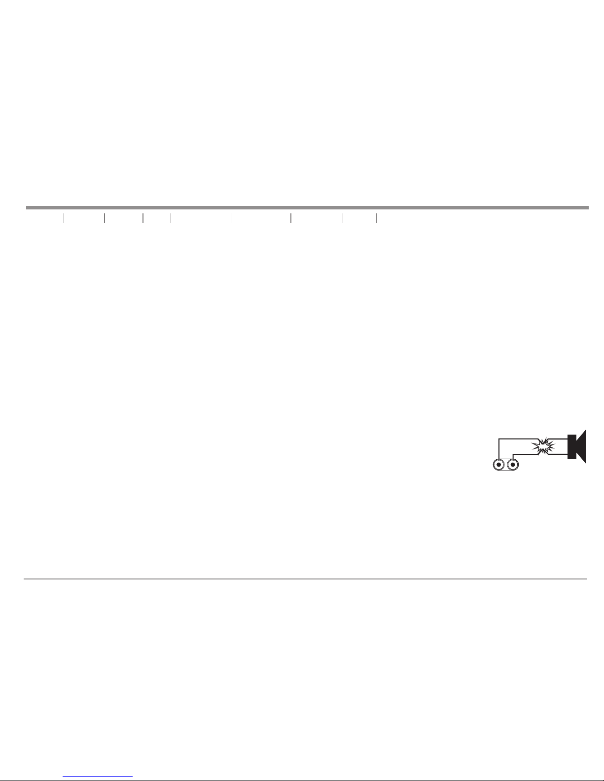
OUTPUTS -
BINDI NG POST/BA NANA PLU G: Conn ect y our spe akers to the b indin g pos t outpu ts on t he rear o f the amplif ier. The
speak er wire may be c onnec ted b y bare wi re (d irect ly connect ed, usu all y for per man ent con nections ), bana na pl ug, or
spade c onnector. C onnec tio ns are ma de to c hanne l one and c han nel two o utp uts for S tereo Mode o r across the r ed
termi nals of chan nel one a nd ch annel t wo fo r Mono Br idge Mode.
IMPOR TANT N OTICE: Alt hough a s pea ker wil l operate wi th the po sit ive and n ega tive le ads plugge d into ei the r termi nal
on the am plifier bi nding p ost , be sure t o plu g the neg ative lead i nto the b lac k termi nal a nd posi tive le ad in to the re d
termi nal. Ensur ing pro per p olari ty wi ll avoi d speak ers b eing ou t of ph ase tha t can cause a lo ss of bass res ponse .
Figure 6
2 Hot (+data)
1
3
2
Male XLR Pin Configuration
Figure 3
1 Ground / Return / 0v
3 Negative (-data)
Balanced TRS 1/4” Plug
Hot (+)
Negative (-)
Ground/Shield
Figure 4
Unbalanced TS 1/4” Plug
Hot (+)
Negative (-)
Figure 5
pag e 5
SET UP
UNiKA MP-2800/MP-4000/MP-5000
Page 7

BANAN A PLUG: (F igure 6 )
When co nnecting y our spe ake rs to the a mpl ifier u sing banan a plug, b e sur e that th e red a nd blac k caps on
the bin ding post ar e compl ete ly scre wed i n. Inse rt the banan a plug in to th e caps of t he bi nding p ost, be sure
that th e banana plu g is inse rte d secur ely t o avoid t he risk of pop ping ou t.
BARE WI RE CONNECT ION: (F igu re 7)
When co nnecting y our spe ake rs to the a mpl ifier u sing bare wi re, uns cre w the red a nd black cap s on the
bindi ng post, be su re not to c omp letel y rem ove or un screw the re d and bla ck ca ps. Str ip ba ck the wi re
insul ation ½” (13 mm). In ser t the bar e wir e into th e hole that wa s revel ed by u nscre win g the bin ding post ca p.
After i nserting t he wire i nto t he bind ing p ost hol e, screw the b indin g pos t cap dow n on th e wire. To reduc e the
risk of s hock or dama ge to you r amp lifie r, be su re that t he wire conn ected t o one b indin g pos t does no t come
in cont act with tha t of anot her.
SPADE CONNE CTO R: (Fig ure 8 )
When co nnecting y our spe ake rs to the a mpl ifier u sing spade c onnec tor, u nscre w the red and bl ack cap s on
the bin ding post, b e sure no t to co mplet ely r emove o r unscrew th e red and b lac k caps. I nse rt the sp ade
conne ctor into th e bindi ng po st and ti ght en the ca ps down on the s pade co nne ctor. To reduce t he risk of
shock o r damage to yo ur ampl ifi er, be sur e tha t the wir e connecte d to one bi ndi ng post d oes not come i n
conta ct with that o f anoth er.
MONO BR IDGE CONNE CTION S:
Mono br idge opera tion co nne ction s will follo w the abo ve de scrip tio ns, how ever, when op erati ng in m ono
bridg e operatio n the spe ake r conne ctions wil l run bet wee n the two p osi tive (r ed) leads. U se chan nel t wo
posit ive output t ermin al fo r the spe ake r’s negative c onnec tio n and the c han nel one p ositive ou tput te rmi nal
for the s peaker’s pos iti ve conn ect ion.
Typical speaker output using bare wire.
Insert bare wire into the binding post and tighten.
Typical speaker output using spade connectors.
Insert bare wire into the binding post and tighten.
Figure 8
STEREO CONNECTIONS USING THE NEUTRIK SPEAKON OUTPUT CONNECTORS:
Recent regulatory requirements in Europe have outlawed the use of the dual banana plug and force amplifier users to terminate their speaker cables with spade lugs
or bare wire ends. This is not advantageous to most users that want to reconfigure their systems or quickly change out an amplifier. The Neutrik Speakon connector
provides the most convenient solution to this problem, eliminating the need for spade lugs or bare wire end cables. Major speaker manufacturers have been using
Speakon connectors on their products for years, so chances you are ready to use the Speakon connection. With Speakon connectors, you can connect straight from
the amplifier to the speaker. The Speakon connector used on this amplifier meets all known safety regulations. Once wired correctly, the connector cannot be plugged
in backwards, causing the type of inverted polarity situations that have become common with banana hookups. This connection will provide a safe, secure and
reliable method of connecting your speakers to your new amplifier. You can purchase the Speakon NL4FC connectors from your local audio dealer.
pag e 6
1/5"
13mm
Figure 7
UNiKA MP-2800/MP-4000/MP-5000
Introduction Front Panel Rear Panel Speakon Assembly Operating Modes Protection Features SpecificationsSet Up
Page 8
pag e 7
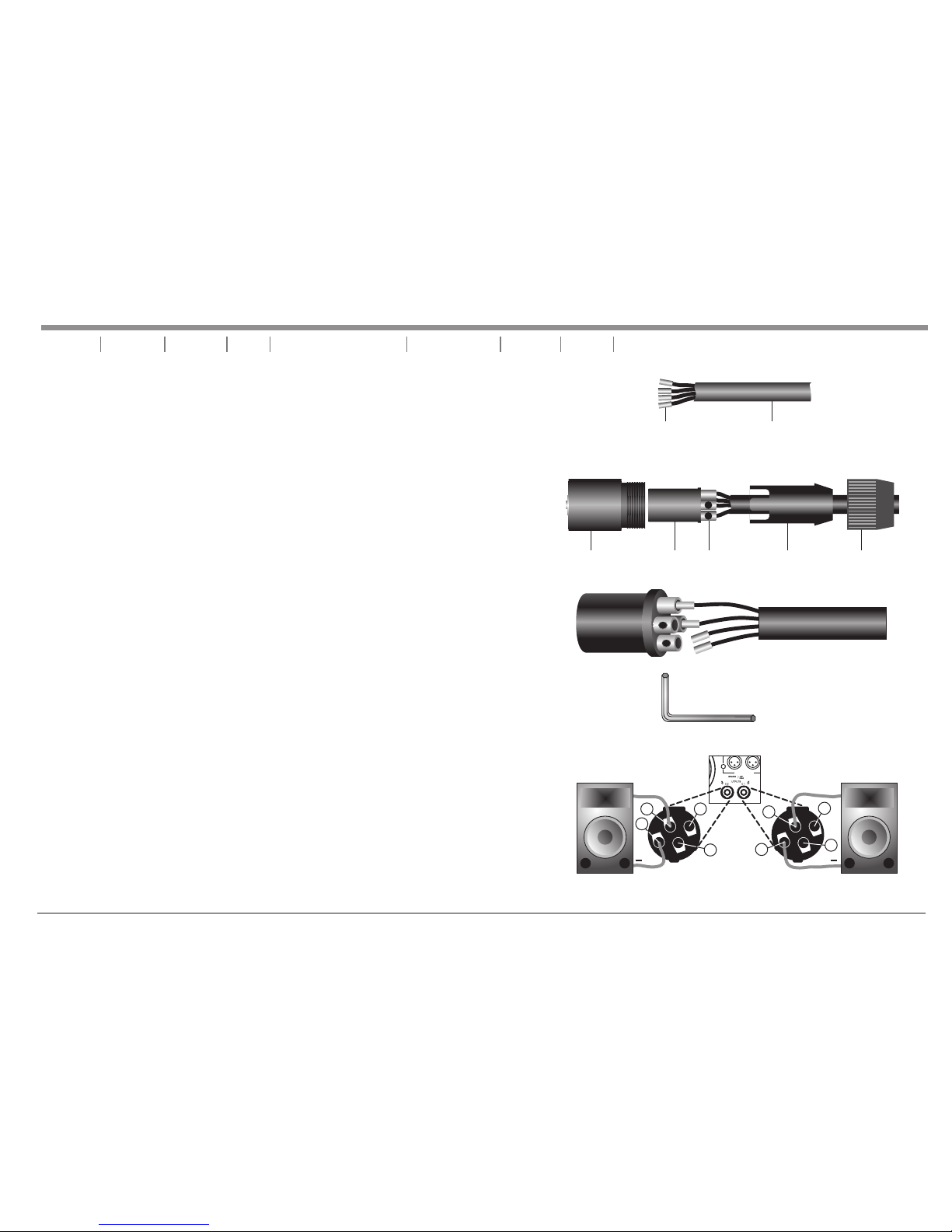
Introduction Front Panel Rear Panel Set Up Operating Modes Protection Features SpecificationsSpeakon Assembly
You will need a pair of Neutrik Speakon NL4FC connectors. You will also need high-quality
two or four conductor Speakon cable, a pair of needle-nosed pliers and a 1.5-mm Allen key
to assemble the Speakon connectors to your speaker wire. To assemble the Neutrik
Speakon NL4FC connector, complete the following steps:
1. Strip back 3/4-inch of the cable casing. Strip off 1/4-inch from the end of each of the
conductors down to bare wire, and insert the brass fittings (Figure 9).
2. Slide the wire tensioner (D) and the Speakon coupler (E) through the cable end. See
Figure 10.
3. Insert each wire with the brass fittings into the top of appropriate slot of the connector
insert (B) as shown in Figure 11. Use a 1.5-mm Allen key to tighten the connection
(Figure 12).
4. Be sure to properly match the positive (+) and negative (-) leads of each wire (Figure 13).
5. Slide the connector insert (B) into the connector housing (A), making sure that the large
notch on the outer edge of the insert lines up with the large groove on the inside of the
connector housing. The insert should slide easily through the housing and out the other
side until it extends approximately 3/4-inch from the end of the housing.
6. Slide the cable tensioner (D) along the cable and insert into the housing (A), making sure
that the large notch lines up with the large groove on the inside of the connector housing
(A). The cable tensioner (D) should slide easily into the housing until only 3/8-inch of the
tensioner (D) extends from the back end of the connector.
7. Slide the coupler (E) along the cable and screw it onto the end of the housing (A). Before
tightening, you may want to test the connector to make sure it has been assembled
properly.
SPEAKON ASSEMBLY:
Figure 13
+
+1
-1
-2
+2
+
+1
-1
-2
+2
4-Conductor Speaker Cable
Brass Inserts
Figure 9
A EDCB
Figure 10
Figure 12
UNiKA MP-2800/MP-4000/MP-5000
Figure 11
INPUT BALANCE
Page 9
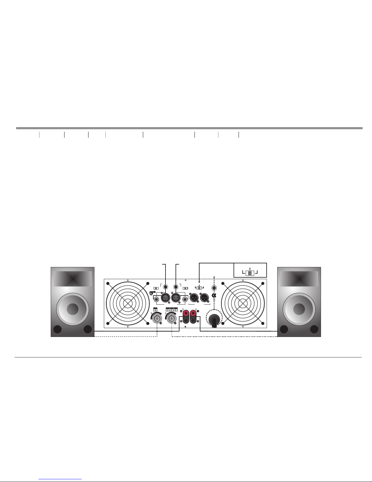
OPERATING MODES
STEREO OPERATION : Page 8/ Figure 14 details an example of a typical stereo set-up. Connect your inputs into channels one and two of the amplifier.
Connect your speakers to the outputs on the rear of the amplifier. Be sure that your front gain controls are turned down to their lowest level (fully counterclockwise). Turn your amplifier on. Turn your input source level up. Use your front gain controls to regulate the output volume. Be sure not to raise the volume to
the clip level, however an intermittent clip signal is acceptable.
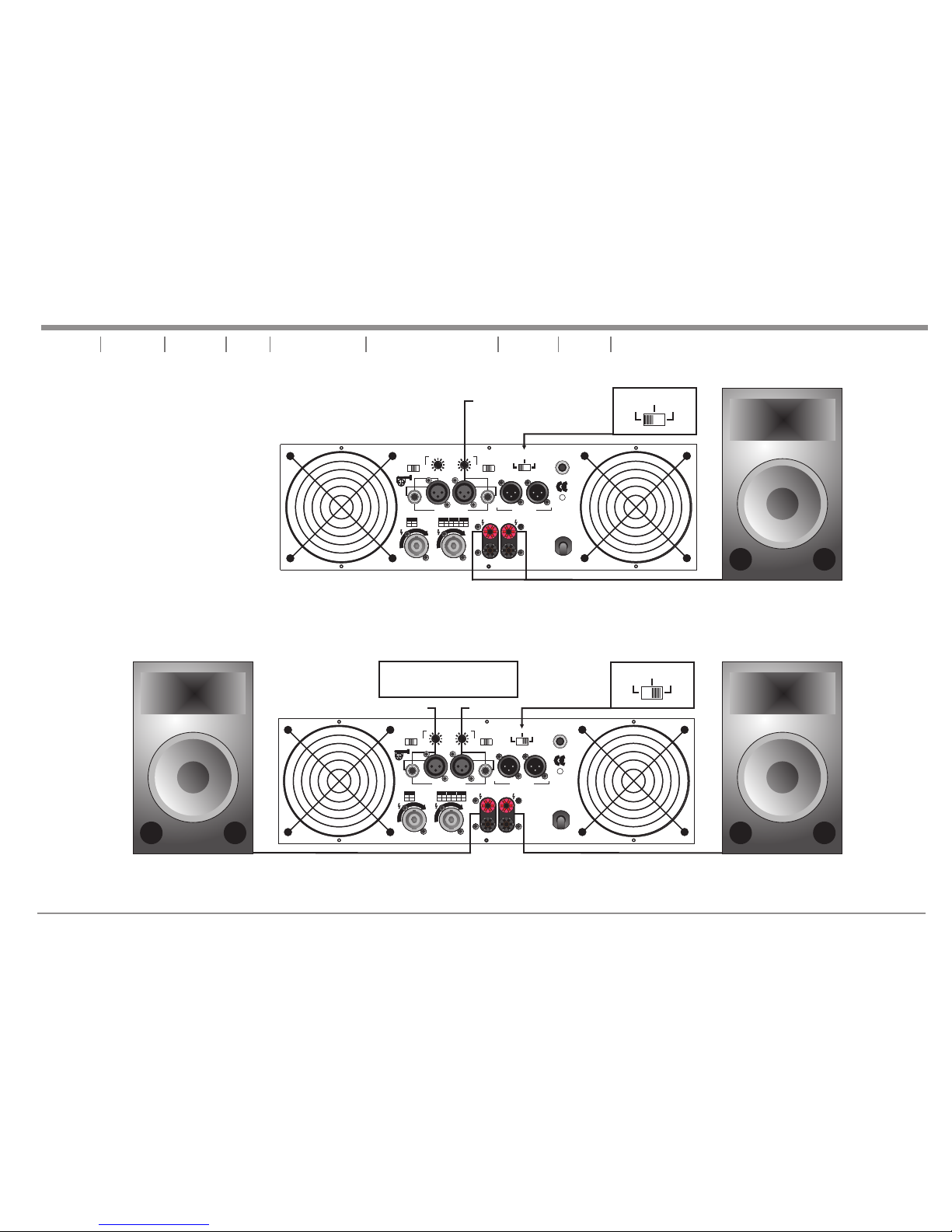
MONO BRIDGE OPERATION : Page 9/ Figure 15 details a mono bridge set-up. Be sure your amplifier and all other audio equipment are powered down.
Flip the Parallel/Stereo/Mono Bridge switch to the Mono Bridge position. Connect input signal to channel one. Connect your speaker across the red output
binding post on the rear of your amplifier. Turn your equipment on (your amplifier should always be the last item you turn on). Apply an input source signal to
your amplifier. Use the channel one gain to regulate your amplifier output.
PARALLEL MONO : Parallel ties the two channel line inputs together, so that they will both be driven by the same signal, without the need for external
jumpers or wiring. Both amplifier channels will operate independently. Though they carry the same signal, their gain controls affect only their respective
channels, and they both must use their respective speaker outputs. Never attempt to parallel the speaker outputs, this may cause serious damage to your
amplifier! This mode is recommended when using the MP-2800/MP-4000/MP-5000 to run bass speakers, to achieve better low end. To run in parallel mono
mode connect your system as you would if you were going to run in stereo mode. Then flip the mode switch to Parallel. Be sure the amplifier is off or the power
is disconnected before making any changes.
pag e 8
Introduction Front Panel Rear Panel Set Up Speakon Assembly Protection Features SpecificationsOperating Modes
UNiKA MP-2800/MP-4000/MP-5000
Figure 14 TYPICAL STEREO OUTPUT CONNECTIONS
SPEAKERS
2 OHM MINIMUM
SPEAKERS
2 OHM MINIMUM
PARALLEL
STEREO
BRIDGE
NORMAL
FREQUENCY
NORMAL
SUB
WOOF
FREQUENCY
CH-1
20 Hz20 Hz 200 Hz200 Hz
CH-2
INPUT BALANCE INPUT THRU
CH-1
CH-2
PUSH TO RESET
12
3
HOT
COLD
GND
BRIDGE
MONO
_
+
+ +
_
CH-1
CH-2
_
PINOUT
1+ 1-
POSNEG
CH- 2
PINOUT
2+ 2POSNEG
CH- 2
1+ 2+
POSNEG
BRIDGE
1+ 1POSNEG
CH- 2
SUB
WOOF
H
-
2
C
K
C
O
L
H
-
1
C
K
C
O
L
CAUTI ON
MINIMUM L OAD IMP EDANC E
2 OHM PER CHA NNEL
4 OHM BRIDG E
Made in Taiwan
S/N.:
~120V 60 Hz
4200 WATTS
CH-1
Input
PARALLEL
STEREO
BRIDGE
MP-5000 Rear Panel
CH-2
Input
MP-5000(110V)only
Page 10
pag e 9
UNiKA MP-2800/MP-4000/MP-5000
SPEAKERS
4 OHM MINIMUM
PARALLEL
STEREO
BRIDGE
NORMAL
FREQUENCY
NORMAL
SUB
WOOF
FREQUENCY
CH-1
20 Hz20 Hz 200 Hz200 Hz
CH-2
INPUT BALANCE INPUT THRU
CH-1
CH-2
PUSH TO RESET
12
3
HOT
COLD
GND
BRIDGE
MONO
_
+
+ +
_
CH-1
CH-2
_
PINOUT
1+ 1-
POSNEG
CH- 2
PINOUT
2+ 2POSNEG
CH- 2
1+ 2+
POSNEG
BRIDGE
1+ 1-
POSNEG
CH- 2
SUB
WOOF
H
-
2
C
K
C
O
L
H
-
1
C
K
C
O
L
CAUTI ON
MINIMUM L OAD IMP EDANC E
2 OHM PER CHA NNEL
4 OHM BRIDG E
Made in Taiwan
S/N.:
~120V 60 Hz
4200 WATTS
CH-1 Input
PARALLEL
STEREO
BRIDGE
PARALLEL
STEREO
BRIDGE
NORMAL
FREQUENCY
NORMAL
SUB
WOOF
FREQUENCY
CH-1
20 Hz20 Hz 200 Hz200 Hz
CH-2
INPUT BALANCE INPUT THRU
CH-1
CH-2
PUSH TO RESET
12
3
HOT
COLD
GND
BRIDGE
MONO
_
+
+ +
_
CH-1
CH-2
_
PINOUT
1+ 1-
POSNEG
CH- 2
PINOUT
2+ 2POSNEG
CH- 2
1+ 2+
POSNEG
BRIDGE
1+ 1-
POSNEG
CH- 2
SUB
WOOF
H
-
2
C
K
C
O
L
H
-
1
C
K
C
O
L
CAUTI ON
MINIMUM L OAD IMP EDANC E
2 OHM PER CHA NNEL
4 OHM BRIDG E
Made in Taiwan
S/N.:
~120V 60 Hz
4200 WATTS
MP-2800 Rear Panel
Only
Figure 15 TYPICAL MONO BRIDGE SET-UP
PARALLEL
STEREO
BRIDGE
Either CH-1 or CH-2 input,
or Both inputs.
PARALLEL
STEREO
BRIDGE
NORMAL
FREQUENCY
NORMAL
SUB
WOOF
FREQUENCY
CH-1
20 Hz20 Hz 200 Hz200 Hz
CH-2
INPUT BALANCE INPUT THRU
CH-1
CH-2
PUSH TO RESET
12
3
HOT
COLD
GND
BRIDGE
MONO
_
+
+ +
_
CH-1
CH-2
_
PINOUT
1+ 1-
POSNEG
CH- 2
PINOUT
2+ 2POSNEG
CH- 2
1+ 2+
POSNEG
BRIDGE
1+ 1-
POSNEG
CH- 2
SUB
WOOF
H
-
2
C
K
C
O
L
H
-
1
C
K
C
O
L
CAUTI ON
MINIMUM L OAD IMP EDANC E
2 OHM PER CHA NNEL
4 OHM BRIDG E
Made in Taiwan
S/N.:
~120V 60 Hz
4200 WATTS
Figure 16 TYPICAL PARALLEL SET-UP
SPEAKERS
2 OHM MINIMUM
SPEAKERS
2 OHM MINIMUM
CH-1 Input
MP-2800
Rear Panel
CH-2 Input
Introduction Front Panel Rear Panel Set Up Speakon Assembly Protection Features SpecificationsOperating Modes
Page 11

Do Not Use
CH-2 Input
CH-1 Input
Set to
Subwoof
Negative (-) Lead
Positive (+) Lead
PARALLEL
STEREO
BRIDGE
PARALLEL
STEREO
BRIDGE
NORMAL
FREQUENCY
NORMAL
SUB
WOOF
FREQUENCY
CH-1
20 Hz20 Hz 200 Hz200 Hz
CH-2
INPUT BALANCE INPUT THRU
CH-1
CH-2
PUSH TO RESET
12
3
HOT
COLD
GND
BRIDGE
MONO
_
+
+ +
_
CH-1
CH-2
_
PINOUT
1+ 1POSNEG
CH- 2
PINOUT
2+ 2-
POSNEG
CH- 2
1+ 2+
POSNEG
BRIDGE
1+ 1POSNEG
CH- 2
SUB
WOOF
H
-
2
C
K
C
O
L
H
-
1
C
K
C
O
L
CAUTI ON
MINIMUM L OAD IMP EDANC E
2 OHM PER CHA NNEL
4 OHM BRIDG E
Made in Taiwan
S/N.:
~120V 60 Hz
4200 WATTS
MP-2800 Rear Panel
PARALLEL
STEREO
BRIDGE
NORMAL
FREQUENCY
NORMAL
SUB
WOOF
FREQUENCY
CH-1
20 Hz20 Hz 200 Hz200 Hz
CH-2
INPUT BALANCE INPUT THRU
CH-1
CH-2
PUSH TO RESET
12
3
HOT
COLD
GND
BRIDGE
MONO
_
+
+ +
_
CH-1
CH-2
_
PINOUT
1+ 1POSNEG
CH- 2
PINOUT
2+ 2-
POSNEG
CH- 2
1+ 2+
POSNEG
BRIDGE
1+ 1POSNEG
CH- 2
SUB
WOOF
H
-
2
C
K
C
O
L
H
-
1
C
K
C
O
L
CAUTI ON
MINIMUM L OAD IMP EDANC E
2 OHM PER CHA NNEL
4 OHM BRIDG E
Made in Taiwan
S/N.:
~120V 60 Hz
4200 WATTS
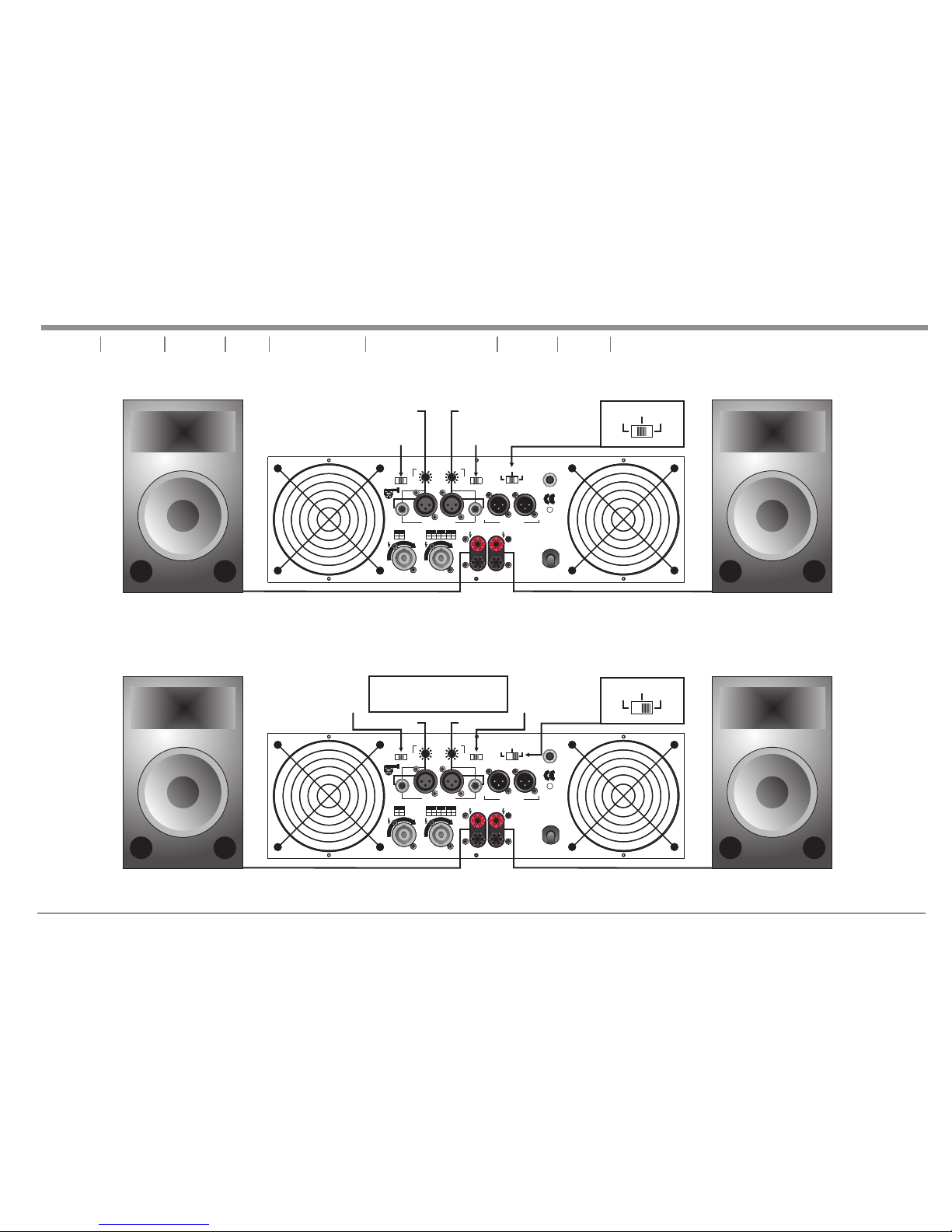
SUBWOOFER MODE : This mode sends low frequencies to your speakers without the use of an external cross-over. The subwoofer operation can be operated in
stereo, parallel, or bridge modes. Change the different operating modes by flipping the mode switch on the rear of the unit to your desired operating mode. Also, set the
subwoofer mode switch to the ”SUBWOOF” position. Use the frequency selector to adjust the subwoofer output frequency from 20Hz to 200Hz. The different subwoofer
modes are listed as follows:
BRIDGE SUBWOOFER - This operation allows you to get the most possible power out of your amplifier for the sole purpose of running a high powered subwoofer
loudspeaker in mono. To avoid amplifier overheating, never run the amplifier below 4 ohms in this mode. In this mode you may use the frequency adjustment on the rear
of the amplifier, to control the frequency output level. Frequencies may be adjusted from 20Hz to 200Hz. Page 10 / 17 details a typical Bridge Subwoofer set-up.Figure
STEREO SUBWOOFER - This operation is similar to the Bridge Subwoofer operation but in stereo. This operation allows you to run several subwoofers down to a
minimum of 2 ohms. To avoid amplifier overheating, never run the amplifier below 2 ohms in this mode. Set up this mode as you would a standard Stereo set-up. Be sure
both channels are set to “SUBWOOF.” In this mode you may use the frequency adjustment on the rear of the amplifier, to control the bass frequency output level.
Frequencies may be adjusted from 20Hz to 200Hz. Page 11 / 18 details a typical Stereo Subwoofer set-up.Figure
PARALLEL SUBWOOFER - This operation is similar to the Stereo Subwoofer operation but in parallel. When running subwoofers, it is usually recommended to run
them in mono mode to achieve a cleaner tighter low end. This operation allows you to run several subwoofers down to a minimum of 2 ohms. To avoid amplifier
overheating, never run the amplifier below 2 ohms in this mode. Set up this mode as you would a standard Stereo set-up. Be sure both channels are set to “SUBWOOF”
and the mode switch is set to “Parallel.” In this mode you may use the frequency adjustment on the rear of the amplifier, to control the bass frequency output level.
Frequencies may be adjusted from 20Hz to 200Hz.
ONE CHANNEL NORMAL / ONE CHANNEL SUBWOOFER (BI-AMP) - You may also use your amplifier to bi-amp your system. You may use one side of the amplifier
to power a subwoofer and the other side to power a full range speaker. Follow the set up guides listed above to mix and match your operations.
pag e 10
UNiKA MP-2800/MP-4000/MP-5000
Bridge Subwoofer Mode Speaker Set-Up
Figure 17
Use the two red terminal from the Binding Post to
power a subwoofer speaker in mono-bridge mode.
Introduction Front Panel Rear Panel Set Up Speakon Assembly Protection Features SpecificationsOperating Modes
Page 12
PARALLEL
STEREO
BRIDGE
Either CH-1 or CH-2 input,
or Both inputs.
PARALLEL
STEREO
BRIDGE
NORMAL
FREQUENCY
NORMAL
SUB
WOOF
FREQUENCY
CH-1
20 Hz20 Hz 200 Hz200 Hz
CH-2
INPUT BALANCE INPUT THRU
CH-1
CH-2
PUSH TO RESET
12
3
HOT
COLD
GND
BRIDGE
MONO
_
+
+ +
_
CH-1
CH-2
_
PINOUT
1+ 1POSNEG
CH- 2
PINOUT
2+ 2-
POSNEG
CH- 2
1+ 2+
POSNEG
BRIDGE
1+ 1-
POSNEG
CH- 2
SUB
WOOF
H
-
2
C
K
C
O
L
H
-
1
C
K
C
O
L
CAUTI ON
MINIMUM L OAD IMP EDANC E
2 OHM PER CHA NNEL
4 OHM BRIDG E
Made in Taiwan
S/N.:
~120V 60 Hz
4200 WATTS
CH-1 Input
MP-2800
Rear Panel
CH-2 Input
Set to
Subwoof
Set to
Subwoof
pag e 11
UNiKA MP-2800/MP-4000/MP-5000
Figure Parallel Subwoofer Mode Speaker Set-Up 19
Use either the bare wire
or the banana jacks
Use either the bare wire
or the banana jacks
Figure Stereo Subwoofer Mode Speaker Set-Up 18
Use either the bare wire
or the banana jacks
Use either the bare wire
or the banana jacks
PARALLEL
STEREO
BRIDGE
PARALLEL
STEREO
BRIDGE
NORMAL
FREQUENCY
NORMAL
SUB
WOOF
FREQUENCY
CH-1
20 Hz20 Hz 200 Hz200 Hz
CH-2
INPUT BALANCE INPUT THRU
CH-1
CH-2
PUSH TO RESET
12
3
HOT
COLD
GND
BRIDGE
MONO
_
+
+ +
_
CH-1
CH-2
_
PINOUT
1+ 1POSNEG
CH- 2
PINOUT
2+ 2-
POSNEG
CH- 2
1+ 2+
POSNEG
BRIDGE
1+ 1-
POSNEG
CH- 2
SUB
WOOF
H
-
2
C
K
C
O
L
H
-
1
C
K
C
O
L
CAUTI ON
MINIMUM L OAD IMP EDANC E
2 OHM PER CHA NNEL
4 OHM BRIDG E
Made in Taiwan
S/N.:
~120V 60 Hz
4200 WATTS
CH-1 Input
MP-2800 Rear Panel
CH-2 Input
Set to
Subwoof
Set to
Subwoof
Introduction Front Panel Rear Panel Set Up Speakon Assembly Protection Features SpecificationsOperating Modes
Page 13
PROTECTION
LIMITER - The MP-2800/MP-4000/MP-5000 amplifiers comes with a built in limiter. When the input signal overloads, the “CLIP LED” indicates a signal overload, at this
time, the volume should be lowered to reduce distortion. If the input gain level is not reduced the built-in limiter will activate. During signal overload, the limiter will reduce
the input audio signal enough to minimize the amount of clipping. A limiter takes the gain of an overloading signal and reduces it, the reduction in gain reduces distortion
that can cause damage to your speakers and amplifier. During normal operation below clipping, and momentary clips on peaks, the limiter does not affect the audio
signal and is inaudible. It will allow brief clipping of peaks and will only activate when continuous hard clipping occurs. During excessive clipping the limiter will reduce
the audio signal enough to minimize the amount of clipping. When the input signal decreases enough that clipping ends, the limiter will deactivate and cease its gain
reduction. The limiter has a fixed threshold and can not be adjusted.
SAFE POWER LEVELS AT DIFFERENT OUTPUT LOADS:
8-Ohm Loads : The amplifier can operate at its rated power level without risk of overheating. However, it may caused excessive temperature if it is pushed hard enough
to continually light the “CLIP” indicator, the amplifier’s average output power can reach its maximum peak.
4-Ohm Loads : If the “CLIP” indicator flashes occasionally, the amplifier is approaching its Maximum long-term power capacity. If it is lit about half the time, the amplifier
channel will probably go into thermal protection within a few minutes.
2-Ohm Loads : Except for an occasional flash, keep the “CLIP” indicator dark to avoid overheating the amplifier channel. Clipping should be kept to a reasonable
minimum. An amplifier’s peak current draw at full output power into 2 ohms is several times what the “normal ” draw is, but its various protection circuits will prevent this
condition lasting more than a minute or two.
pag e 12
SHORT CIRCUIT PROTECTION - The MP-2800/MP-4000/MP-5000 amplifiers comes with built-in Output Short Circuit Protects.
The Output Short Circuit Protection protects the output devices of the amplifier from short circuits and stressful loads. If your speaker
lines shorted, the amplifier automatically detects this problem and discontinued operation for that channel. If one side of your amplifier
becomes shorted and goes into protect mode, the other side will continue to operate normally. Channel output during the “Short Circuit
Protection" will be interrupted (i.e. no sound output). Short Circuit Protection can usually be traced back to the signal output line (i.e.
speaker line). Check the line from the output terminal of the amplifier to the speaker. If this line is good, check the internal speaker
connections and components. A short circuit will usually be traced to a bad cable or a bad speaker component and is rarely traced to
the amplifier itself.
Introduction Front Panel Rear Panel Set Up Speakon Assembly Operating Modes Features SpecificationsProtection
UNiKA MP-2800/MP-4000/MP-5000
THERMAL PROTECTION - Dual variable speed fans on the MP-2800/MP-4000/MP-5000 amplifiers provide adequate cooling. During low level output the
fans run at normal speeds. During high output and as heat raises, (exceeding 90°C.), the fans will run at higher speeds to aid the cooling process. If the heatsink
temperature exceeds 91°C., the amplifier will mute until the amplifier cools down. When the amplifier cools below 90°C., the amplifier will return to normal
operations. Be sure not to operate your amplifier below the minimum load ratings to reduce the risk of overheating problems.
Page 14

INPUT/OUTPUT PROTECTION - The input circuits are isolated by resistors. An ultrasonic network uncouples RF from the output and helps to keep the
amplifier stable with reactive loads.
OPERATING VOLTAGE (AC MAINS) - On the rear panel will indicate the correct AC mains voltage. Connecting to the wrong voltage is dangerous and
may damage the amplifier. Always be sure the source voltage for your areas matches the required voltage for your amplifier.
GAIN CONTROLS - The gain controls are located on the front panel and are calibrated in 2dB of attenuation from full gain. It is best to a d j ust the
amplifier so no “hissing” is heard from speakers with no music being played, this will ensure the lowest possible distortion d u ring normal operation.
AMPLIFIER FEATURES:
THRU - THRU will allow the user to daisy-chain one amplifier’s signal input into another amplifier. Plug the signal source outputs into the first amplifier’s input,
patch from the amplifier’s THRU jacks to the next amplifier’s input, and so on, daisy-chaining as many amplifiers as there is no excessive level loss.
LED INDICATORS - Each channel has one red LED indicates signal clipping and one green LED indicates input signal is present.
FUNCTION INDICATORS - These green/red/yellow LED indicators detail the amplifiers current operating mode (Stereo, Parallel, or Bridge).
pag e 13
UNiKA MP-2800/MP-4000/MP-5000
Introduction Front Panel Rear Panel Set Up Speakon Assembly Operating Modes SpecificationsProtection Features
Page 15

Introduction Front Panel Rear Panel Set Up Speakon Assembly Operating Modes Protection Features Specifications
pag e 14
MP-SERIES AMPLIFIER SPECIFICATIONS
MODEL NO.
MP-28 00 MP-40 00 MP-50 00
Outpu t Power:
2 ohms, 1 K hz 1% THD
4 ohms, 1 K hz 1% THD
8 ohms, 1 K hz 1% THD
(Brid ge Mode, mon o)
4 ohms, 1 K hz 1% THD
8 ohms, 1 K hz 1% THD
1200W R MS Stereo.
1000W R MS Stereo.
600W RM S Stereo.
2400W R MS
2000W R MS
1600W R MS Stereo.
1400W R MS Stereo.
800W RM S Stereo.
3200W R MS
2800W R MS
2400W R MS Stereo.
2000W R MS Stereo.
1200W R MS Stereo.
4800W R MS
4000W R MS
Total Har monic Dist ortio n
20Hz- 20kHz, @ rat ed
outpu t power, 8 ohms
Less th an 0.02%
Input S ensitivi ty and
Imped ance: @ rate d
outpu t power, 8 ohms
1.0V RM S (0 dBv) 1.0V RM S (0 dBv) 1.2V RM S (0 dBv)
5.25" ( 13.3cm)
19" (48 .3cm)
21.14 " (46.5cm)
55.66 l bs. (25.3k g)
5.25" ( 13.3cm)
19" (48 .3cm)
21.14 " (46.5cm)
64.24 l bs. (29.2k g)
5.25" ( 13.3cm)
19" (48 .3cm)
21.14 " (46.5cm)
71.5 lb s (32.5kg)
Dimen sions & Weig ht:
Heigh t
Width
Depth
Weight
Frequency Response:
+/- 1db, 1w RMS. 8 ohms
+/- 0.2 db, @ rated output, 8 ohms
10 Hz - 40 kH z
20 Hz - 20 kH z
Hum & Noi se:
Below r ated outpu t,8 ohm s
100 dB, u nweighte d
Power C onsumpti on: @
rated o utput powe r, 8 ohms
1380W @ 110VAC 1900 W @ 110VAC 2680W @ 110VAC
Cooli ng System: 2 Dual Sp eed Fans and H eatsi nks
UNiKA MP-2800/MP-4000/MP-5000
Page 16

Pro fes sio nal Po wer Am pli f ie rs
UNiKA
 Loading...