

Page 1
GB
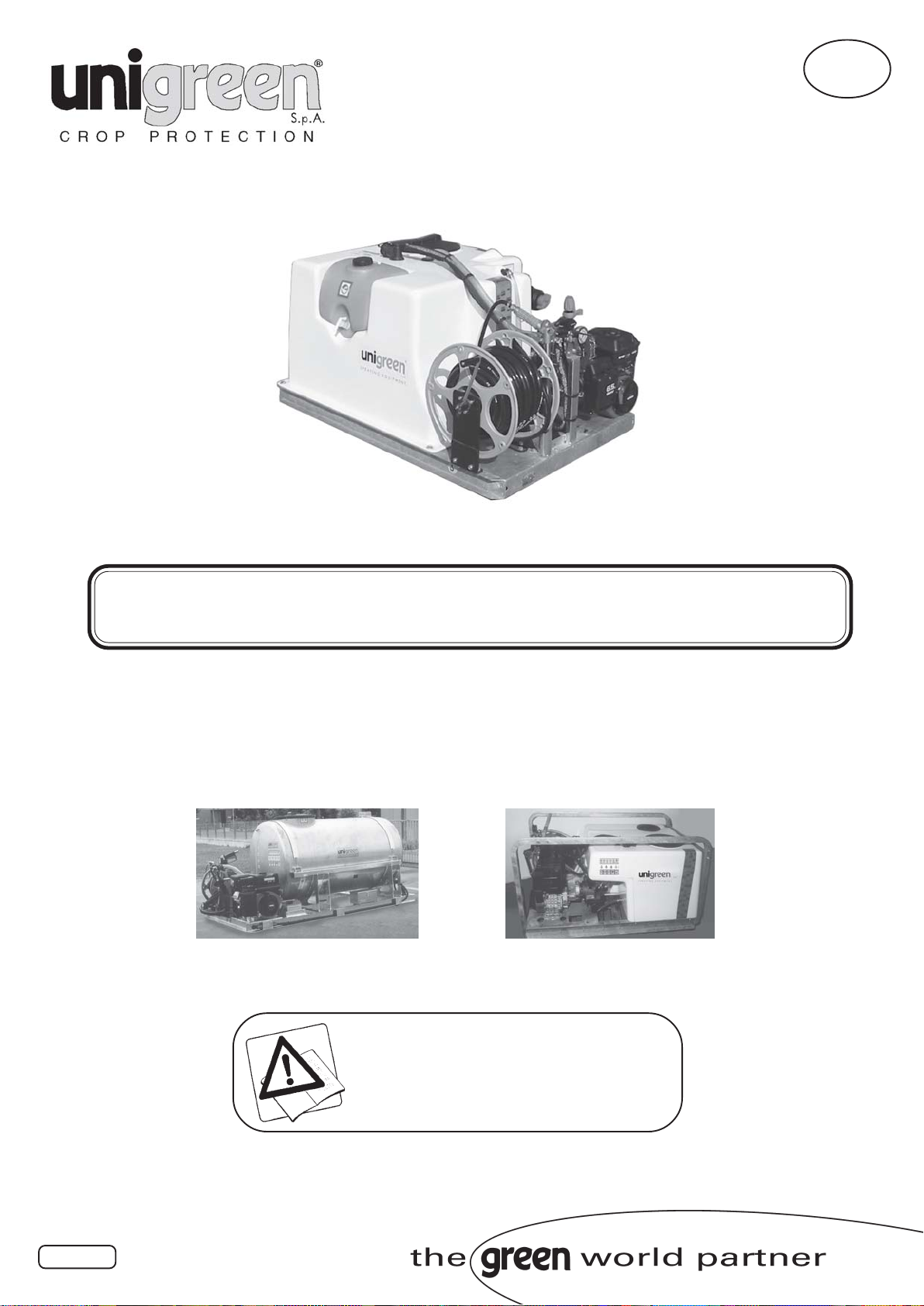
USE AND MAINTENANCE MANUAL
UMP - MASTER
serie MASTER 20/40/50/55
09/2010
Read this manual carefully before use
1
Page 2

2
Page 3

Summary
1 USING AND KEEPING THE USE AND MAINTENANCE MANUAL .................... 4
1.1 COMPOSITION OF THE MANUAL ....................................................................................... 4
1.2 GUARANTEE ....................................................................................................................... 4
1.3 PRODUCT RESPONSIBILITY .............................................................................................. 4
1.4 WARNING SIGNS IN THE MANUAL AND ON THE MACHINE ............................................. 4
2 SAFETY REGULATIONS AND RESIDUAL RISKS .............................................. 5
2.1 INTENDED USE ................................................................................................................... 5
2.2 PROHIBITED USE ...............................................................................................................6
2.3 USING CHEMICAL PRODUCTS .......................................................................................... 6
2.3.1 REGULATIONS FOR THE USE OF CHEMICAL PRODUCTS ............................................... 6
2.4 RECOMMENDATIONS ......................................................................................................... 6
2.4.1 TAKING PRECAUTIONS AGAINST FIRE HAZARDS ........................................................... 7
2.5 MACHINES DESIGNED TO BE USED ONLY WITH CLEAN WATER .................................... 7
2.7 WEATHER CONDITIONS ..................................................................................................... 7
2.8 ROAD CIRCULATION ........................................................................................................... 7
3 CHARACTERISTICS AND SPECIFICATIONS ..................................................... 7
3.1 MACHINE IDENTIFICATION ................................................................................................ 7
3.2 TABLES OF FITTINGS ALLOWED....................................................................................... 7
3.3 NOISE LEVEL OF THE MACHINE ....................................................................................... 7
3.3 STANDARDS OF REFERENCE: ........................................................................................... 8
4 USER’S INSTRUCTIONS ....................................................................................... 8
4.1 TRANSPORTING AND MOVING THE MACHINE ................................................................. 8
4.2 DESCRIPTION OF THE MACHINE ..................................................................................... 8
4.2.1 HAND WASHING TANKS ...................................................................................................... 8
4.3 PRELIMINARY CHECKS...................................................................................................... 9
4.4 APPLICATIONS .................................................................................................................... 9
4.5 MOTORS .............................................................................................................................. 9
4.5.1 ELECTRIC MOTORS ............................................................................................................ 9
4.5.2 INTERNAL COMBUSTION ENGINES (TWO STROKE-PETROL-DIESEL) ........................... 9
4.6 PUMP ..................................................................................................................................10
4.7 SUCTION FILTER ...............................................................................................................10
4.8 PRESSURE REGULATOR ...................................................................................................10
4.8.1 COMPONENTS OF THE PRESSURE REGULATOR ...........................................................10
4.8.2 GENERAL INSTRUCTIONS ................................................................................................11
4.9 DELIVERY FILTERS (ONLY EQUIPPED MODELS) ............................................................ 11
4.10 FILLING THE TANK ............................................................................................................. 12
4.10.1 FILLING WITH THE ANTIPOLLUTION EJECTOR (FIG. 6) ................................................12
4.11 TEST TREATMENT WITH CLEAN WATER ..........................................................................12
4.12 MIXING ............................................................................................................................... 12
4.12.1 MANUAL PREMIXING......................................................................................................... 12
4.12.2 PREMIXER ON COVER (OPTIONAL): ................................................................................12
4.13 WASHING THE SPRAYER ..................................................................................................13
5 HAND LANCES .................................................................................................... 13
6 HOSE REEL .......................................................................................................... 13
8 MAINTENANCE .................................................................................................... 14
8.1 PROGRAMMED MAINTENANCE ........................................................................................14
8.2 EMPTYING TANK................................................................................................................14
8.3 ROUTINE MAINTENANCE ..................................................................................................14
8.4 EXTRAORDINARY MAINTENANCE ................................................................................... 14
8.5 REPAIRS .............................................................................................................................14
8.6 STORAGE IN A WAREHOUSE AND TRANSPORTATION ................................................... 15
8.7 PUTTING BACK INTO SERVICE AFTER WINTER LAYUP ................................................. 15
8.7.1 MATERIALS FOR DEMOLITION ......................................................................................... 15
8.7.2 INDICATIONS FOR A SUITABLE TREATMENT OF WASTE ................................................ 15
8.7.3 ELECTRICAL AND ELECTRONIC APPARATUS WASTE (EEAW) ....................................... 15
FIG. 9 CIRCUIT DIAGRAM .............................................................................................. 16
TABLE 4-5 TABLES OF DELIVERY OF NOZZLES FOR HAND LANCES ...................... 17
TABLE 8 PROBLEMS, CAUSES AND SOLUTIONS .......................................................... 18
TABLE 7 TABLE OF PROGRAMMED MAINTENANCE .................................................... 18
TAB.10 ALLOWED FITTINGS ........................................................................................... 19
3
Page 4

Thank you for having chosen UNIGREEN.
The product you purchased has been designed and built with the greatest
attention to the safety of the operator and the environment, nevertheless
there are still some residual risks due to the nature of the product used.
For this reason we recommend reading all of this manual to avoid making
mistakes in the first period of use and to get the most out of the working life of
the sprayer in time, doing the programmed maintenance at regular intervals.
1 USING AND KEEPING THE USE AND MAINTENANCE MANUAL
The manual is an integral part of the machine and should be kept in a safe
place where it can be reached easily for consultation.
1.1 COMPOSITION OF THE MANUAL
This manual consists of various parts to make it easier to consult by subject
and to avoid repetitions; the following are part of the manual:
a) pump handbook
b) pressure regulator handbook (manual or electric)
c) spraying computer handbook (if fitted)
d) optional accessories handbooks (marker, premix, cardan shaft, etc.)
UNIGREEN reserves the right to make changes to the manual without prior
warning and the normal printing cycles may vary slightly.
1.2 GUARANTEE
The enclosed card indicates the conditions of the UNIGREEN guarantee. The
UNIGREEN guarantee covers the repair or replacement of parts considered
manufacturing flaws, according to the unquestionable judgement of
UNIGREEN, only after the authorised agent for that zone has verified the
fault.
Ambit of the guarantee
The guarantee doesn’t cover cases of normal wear, negligent use, poor
maintenance and/or improper use.
The following materials subject to normal wear are not covered by the
guarantee: gaskets and seals, diaphragms, seal rings, tubes and pipes,
nozzles, pressure gauges, oil, tyres, friction material of the clutches.
Evident cases of negligence include: work speed over that indicated in the
spraying tables in the handbook (or too high for the conditions of the terrain),
use of herbicide booms without an auto-levelling system or with the autolevelling system blocked, power-takeoff speed over 540 rpm.
Mounted sprayers: activation of the three-point elevator with cardan shaft
engaged and power-takeoff operational.
And anything else indicated in the present Use and Maintenance Manual.
Maintenance:
The guarantee is void if the maintenance indicated in the tables in this manual
isn’t respected, regarding the period and deadline of the interventions, washing
the machine and the circuit at the end of the treatment.
Improper use:
The use the UNIGREEN machines are designed for is indicated in this
manual, any other use is forbidden and makes the guarantee void.
1.3 PRODUCT RESPONSIBILITY
UNIGREEN spa is not responsible if:
a) During the working life of the machine the normal maintenance
operations aren’t performed and documented as indicated in this handbook, in
the enclosed handbooks of the pumps-motors-regulators-etc. and in any case
as is customary for the normal maintenance of mechanical machinery.
b) The machine is equipped with non original accessories or components or
parts that aren’t acknowledged by UNIGREEN as their own.
c) The machine is equipped with original accessories or components that
are unsuitable in the measurements, weight or version for the same.
Please consult the page of available and recommended fittings.
d) Not following the instructions in the manual whether totally or partially.
e) Modifications made to the machine that haven’t been authorised by
UNIGREEN.
Composite handbook, consult the
specific files on the various
components
1.4 WARNING SIGNS IN THE MANUAL AND ON THE MACHINE
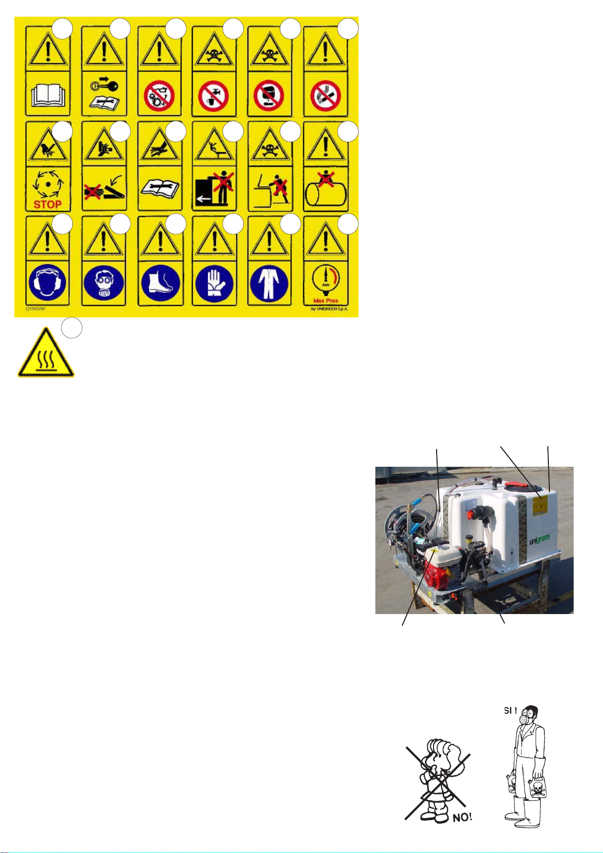
Below you will find all of the pictograms on the machine, in order to illustrate
the warnings, the prohibitions and the correct method of use.
The operations that require particular attention are shown in the images
4
beside the text.
Page 5
21
21 63 4 5
87 129 10 11
1413 1815 16 17
Key to the symbols
1- Read the Use and Maintenance manual
2- Stop the machine and read the manual before
every intervention
3- Don’t lubricate while running
4- Don’t drink
5- Don’t dispose of residue liquids in the environment
6- No smoking
7- Danger, risk or injury, don’t get near the machine
until the moving machine members have stopped
8- Danger of crushing, don’t get your hands near the
moving mechanical machine members
9- Danger, risk or injury caused by fluids under
pressure
10- Don’t climb on the machine during work or
transfers
11- Don’t climb on the tank
12- Don’t enter in the tank
13- Wearing earmuffs is obligatory
14- Wearing a face mask is obligatory
15- Wearing safety footwear is obligatory
16- Wearing protective gloves is obligatory
17- Wearing protective overalls is obligatory
18- Use a working pressure under that indicated in
red on the manometer.
19- Don’t get your hands near the moving cardan
shaft
20- Make sure power-takeoff of the tractor turns in the
right direction and runs at the right speed.
2 SAFETY REGULATIONS AND RESIDUAL RISKS
In relation to safety, the following terms will be used:
Dangerous zones: any zone inside and/or near the machine where the
presence of a person exposed constitutes a risk for the safety and health of
the same person.
Person exposed: any person who has their body or any part of their body in a
dangerous zone.
Before starting the machine, the operator must check for any visible faults in
the safety devices and the machine itself.
Never start the machine until you have told anyone in the range of action of
the machine to move away and they have done so.
The protective devices must not be removed or disabled when the machine is
running.
It is obligatory to keep all the plates with danger and safety signs in perfect
conditions. If they get damaged or deteriorate, replace them in good time.
Replace parts believed to be faulty with others indicated by UNIGREEN.
NEVER try makeshift or hazardous solutions.
Don’t wear clothes, jewellery, accessories, or anything else that can get
caught in the moving machine members.
Pay the greatest attention to all the warning and danger signs on the machine.
Don’t use the machine for any other purpose other than that indicated in the
manual.
The machine has been designed and built with the appropriate devices to
guarantee the safety of the user.
In any case there are some residual risks associated with the improper use of
the machine by the operator; for this purpose danger signs and symbols and
prohibitions are applied near some parts of the machine (see previous
pictograms).
21- Danger of surfaces at high temperatures (internal
combustion engine)
9 11+12
1
INDICATIVE POSITION OF THE WARNING SIGNS
ON THE SPRAYERS
NB: the position may vary on the basis of the
characteristics of the model.
da 1 a 18
21
2.1 INTENDED USE
The sprayer in this series is built for agricultural use. The materials used are
resistant to normal chemical products used in agricultural spraying (or
herbicides) at the time of construction.
Any other use is not allowed and the manufacturer is not responsible for any
damage caused by aggressive, dense or sticky chemicals.
THE USE OF THE MACHINE BY PERSONS UNDER 18 YEARS OF AGE IS
STRICTLY FORBIDDEN
The use of liquid fertilizers in suspension is not allowed, while the use of the
same in a solution is possible if requested when the machine is ordered from
5
Page 6
Unigreen and in any case changing some of the parts described in the
handbooks of the regulator, such as the manometer (stainless steel), the
nozzles (large diameter ceramic) and eliminating the fine mesh filters to
prevent blockages.
2.2 PROHIBITED USE
Using the machine with the following products is strictly forbidden:
= Paints of any kind and type
= Solvents or thinners for paints of any kind and type
= Combustibles or lubricants of any kind and type
= LPG or gas of any kind and type
= Flammable liquids of any kind and type
= Liquid foodstuffs, whether for animals or humans
= Liquids containing granules or consistent solids
= Mixtures of various incompatible chemical products
= Liquid fertilizer or manure in suspension with lumps and/or that is
particularly dense
= Liquids with a temperature of over 40°C
= Any products that aren’t suitable for the specific use of the machine.
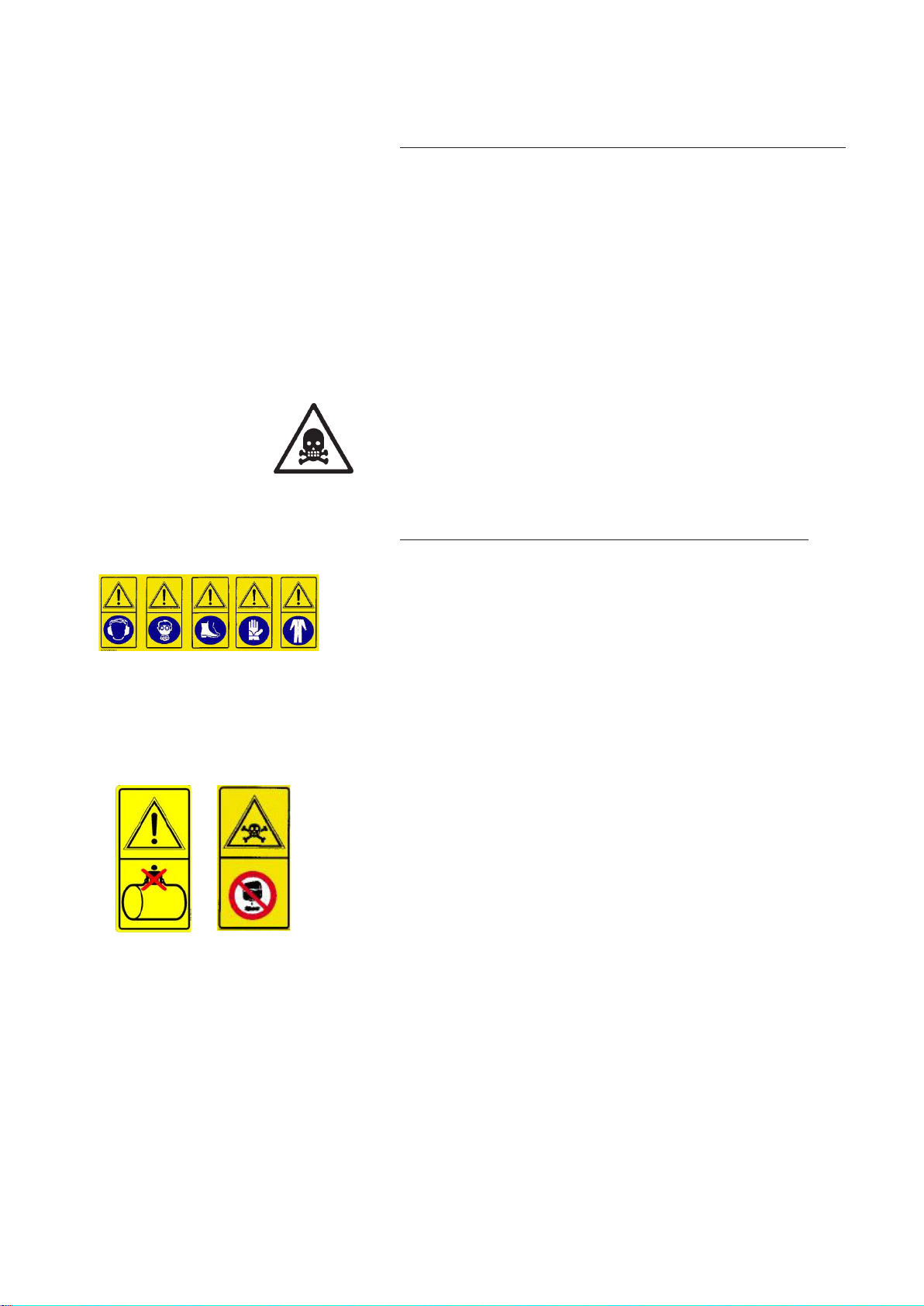
2.3 USING CHEMICAL PRODUCTS
All pesticides or herbicides can be dangerous to humans and the environment
if used erroneously or inadvertently.
Therefore we recommend that only suitably trained persons should use these
products (license) and in any case only after having carefully read the
instructions on the container.
2.3.1 REGULATIONS FOR THE USE OF CHEMICAL PRODUCTS
Some recommendations for avoiding damage and accidents:
= Keep the machine in a suitable, protected place with no access for
children or strangers
= Handle the products with care, wearing rubber acid-proof gloves, gogglesface masks or filtering helmets, overalls made of water-repellent fabrics or
TIVEK and boots made of rubber or similar materials.
= If chemical products or mixtures of product come into contact with the
eyes or are swallowed consult a doctor immediately, taking the label of the
product with you.
= Wash all clothes that come into contact with the chemical, whether
diluted or undiluted, thoroughly before using them again.
= Don’t smoke, drink or eat when preparing or spraying the mix or near or in
the fields treated.
= DON’T ENTER THE TANK: the residues of a chemical product can cause
poisoning and suffocation.
= When spraying, respect safe distances from residential areas, water
courses, roads, sports centres and public parks or paths.
= Thoroughly wash the containers of plant protection products using the
relevant accessories, rinsing several times with clean water. The liquids used
for washing can be used for treatment.
= Collect the washed containers and send them to the relevant collection
centres. Never dispose of them in the environment and don’t use them again
for any other purpose. It is good practice to knock a hole in the bottom of the
tins so they can’t be used again.
= When you have finished spraying, wash the sprayer thoroughly, diluting
the residues with a quantity of water at least 10 times that of the residues,
spraying the resulting mix over the treated field.
2.4 RECOMMENDATIONS a) Refer to the present handbook for the use and maintenance of the frame,
tank, auto-levelling systems, elevators, mechanical and hydraulic herbicide
booms, spray booms and hose reels.
Refer to the enclosed handbooks for the use and maintenance of the pump
and pressure regulator and any accessories or motors.
b) Please contact the agent in your zone, the nearest authorised workshop
or UNIGREEN S.p.A. directly for any repairs the user feels they aren’t capable
of performing alone. (see point 10.4)
c) Due to the complexity of the equipment and the variety of technologies used
(mechanical, hydraulic, oil-pressure and electrotechnical) operators must not
dismantle or modify the equipment. All of the relevant operations must be
6
performed by specialised personnel, authorised by UNIGREEN S.p.A.
Page 7

2.4.1 TAKING PRECAUTIONS AGAINST FIRE HAZARDS
Don’t use naked flames or heat sources near the machines.
The sprayers are made with many materials that derive from petroleum: tanks,
tubes, pipes and hoses, wheels and plastic parts; furthermore the presence of
oils of various nature and residues of chemical products make them potentially
flammable.
2.5 MACHINES DESIGNED TO BE USED ONLY WITH CLEAN WATER
There are versions of the machines designed only to be used with a hose reel
for washing with cold clean water.
These machines cannot be used with chemical products as they don’t have
some of the devices or accessories that are needed to use these products
safely. These machines are identified by the word “washing” on the CE plate.
2.7 WEATHER CONDITIONS
We recommend spraying in the early hours of the morning or late in the
afternoon, avoiding the hottest time of day.
Never do any spraying if it’s raining or rain is forecast.
Don’t spray in strong wind or in any case, in winds above 3/5 m/second.
If you have to spray in windy conditions, use relatively low pressures to obtain
quite large drops that are less sensitive to drifting (being heavier the wind has
less effect). There are also special anti-drift nozzles available from UNIGREEN
S.p.A.; for information, please contact our offices.
2.8 ROAD CIRCULATION
The admissible capacity of the vehicle (pickup or truck) or the trailer upon which
the equipment is positioned should be checked.
The equipment is supplied for application to the floor. In the case of fixed rigging
the vehicle needs to be registered.
You need to check the correct couplings with your area dealer.
3 CHARACTERISTICS AND SPECIFICATIONS
3.1 MACHINE IDENTIFICATION
This handbook is valid for UMP-MASTER sprayers to be used for:
a) treatments with hand lances with or without a hose reel
b) hand lances for washing with or without a hose reel
The UNIGREEN S.p.A. sprayers are identified by the CE plate (FIG. 1 ) bearing
one of the marks indicated in the tables of the allowed fittings (TABLE N° 10 ,
page 19).
3.2 TABLES OF FITTINGS ALLOWED
Table N° 10 let you identify the version of your machine indicating the basic
equipment and all the possible fittings available (optional).
You can also find the other fittings allowed or other versions to meet your
requirements in the future.
THE FITTING DEFINED IN TABLE N° 10 (PAGES 19) SHOULD BE
CONSIDERED BINDING FOR THE VALIDITY OF THE DECLARATION OF
CONFORMITY.
Other fittings or setups of basic components and optionals should be
considered unsafe and therefore are not covered by the guarantee and aren’t
UNIGREEN’s responsibility.
The same goes for fittings realised with components or accessories that aren’t
original UNIGREEN parts.
UNIGREEN accessories can easily be identified by the label with the yellow
background “ORIGINAL UNIGREEN ACCESSORY”
TYPE : .......................................................................
code: ........................................ N˚ ...........................
massa a vuoto: ..........................Kg. max press. : ........... bar
net mass
massa totale ammessa: .............................. Kg.
total mass
via Rinaldi, 105 - Reggio Emilia ITALIA
ANNO
YEAR
20 .......
made in
Italy
FIG. 1
3.3 NOISE LEVEL OF THE MACHINE
Use earmuffs to protect your ears when using the machine, the multi-purpose
Units produce a maximum level of sound pressure inferior to 89 dB (A) and a
level of power inferior to 107Db (A).
Readings taken in accordance with the following standards:
Machines Directive 2006/42/CE
Legislative Decree D.Lgs. n°292 of the 4th of September 2002 concerning the
environmental acoustic emission of machines and equipment for use outdoors.
UNI EN ISO 4254-1:2006.
7
Page 8

3.3 STANDARDS OF REFERENCE:
- MACHINES DIRECTIVE 2006/42/CE.
- D.Lgs. 81/08 Unique text for safety and hygiene in working places.
-UNI EN ISO 12100-1/Apr.2005 : Machinery safety - Fundamental concepts,
general design principles - Part 1: basic terminology, methodology
-UNI EN ISO 12100-2/Apr.2005 : Machinery safety - Fundamental concepts,
general design principles - Part 2: Technical principles
-UNI EN ISO 13857: May 2008 Machinery safety, safe distances to avoid
reaching hazardous areas with upper limbs.
-UNI EN 349/November 2008: Machinery safety, minimum spaces to prevent
crushing of body parts
-UNI EN 907/Nov.1998: Agricultural and forestry machinery - Sprayers and
spreaders of liquid fertilizers - Safety.
-UNI EN ISO 13849-1: February 2007: Machinery safety - Fundamental
concepts, general design principles
-UNI EN 982/January 2009: Machinery safety. Safety requisites relevant to
systems and their components for hydraulic and pneumatic transmissions.
Hydraulics.
-UNI EN ISO 4254-1/June 2006: Agricultural machines - Safety - Part 1:
General requisites
-ISO 11684/1995: Pictograms - general principles.
This symbol
identifies the
coupling points
of the machine
FIG . 2
4 USER’S INSTRUCTIONS
4.1 TRANSPORTING AND MOVING THE MACHINE
If the machine has to be lifted, use suitable slinging and tackle, crane or
bridge crane, with capacity suitable for the use. The dry weight of the machine
at the maximum level of fitting and with all the accessories allowed is
stamped on the nameplate; use slings and lifting gear with a adequate loadbearing capacity.
Don’t stand the sprayer on soft ground or steep slopes.
Never lift or move the sprayers by hand if there is liquid in the tank. The
machine will weigh more and the movement of the liquid can change the
centre of gravity causing uncontrolled movements.
It is opportune to apply the slinging as in FIG.2 for the MASTER 55 model or
those equipped with eyebolts. It is necessary to use forklift trucks or transpallets
with an adequate capacity for other models. The forks should be placed as
indicated in the specific pictograms.
Don’t pass or stand under the machine when it is being lifted.
4.2 DESCRIPTION OF THE MACHINE
The UMP and MASTER machines are made to be mounted on the floor of the
pickup vehicle. Some models can be equipped with wheels and handlebar for
towing by hand or by small tractors.
The frame is in hot galvanised steel, the cisterns are in easy-to-empty organic
glass reinforced with glass fibre. Versions are available with the cistern in
galvanised or stainless steel.
The pumps are generally membrane and in some cases piston and are coaxially
mounted with an electric or internal combustion engine reducer.
They are equipped with an external suction filter that allows easy inspection.
All the machines are equipped with a hose nozzle for watering and/or washing
with a length of tubing.
4.2.1 HAND WASHING TANKS
The sprayers are supplied with an auxiliary hand-washing tank with clean
water and a hand tap.
This tank must always be supplied with water and the inside must be clean so
you can wash any parts of the body that come into contact with the chemical
product used.
Never drink the liquid inside.
8
Page 9

4.3 PRELIMINARY CHECKS
When you receive the machine, check that it is complete and no parts are
missing.
If there are any damaged parts, inform your local reseller or UNIGREEN
directly in good time.
When the machine is delivered, make sure you ask:
a) that the machine is delivered with all of its parts fitted and that the fitting
meets the requisites in table N° 10 (page 19). (This procedure is necessary
because for reasons of space during transportation the machine is often
delivered partially dismantled).
b) that it is tested in your presence in particular checking:
= that the suction filter and the inside of the tank are clean and free of work
residues.
= that the connections are made correctly following the basic layout (FIG.
N° 9, page 16).
= that the hose clips and all the unions and connections are tightened
properly.
= that all of the protective covers are fitted solidly to the machine, in
particular the protective cover of the power-takeoff of the pump.
4.4 APPLICATIONS
The UMP and MASTER machines are made to be mounted on the floors of vans
or similar vehicles. They can also be mounted on automobile type trolleys or
pickup vehicles with sufficient capacity. Always made sure before mounting that
the capacity of the trolley or the vehicle is sufficient. A tow-hook wheel kit NOT
approved for circulation on the road and suitable for small movements within
private areas is supplied on request.
4.5 MOTORS
4.5.1 ELECTRIC MOTORS
The electric motors of the motor-pumps correspond to the regulations in force
envisaged by the low-tension regulation and are guaranteed by the specific plate
of the constructor. The 20 Volt single-phase version is usually supplied with plug
and switch while the 380 Volt three-phase version is usually supplied with a
terminal board and the plug must be installed by an authorised and competent
installer. The plant to which the motor-pump is applied must correspond to the
regulations in force and be served by an automatic differential lifesaver switch.
Never, for whatever reason, direct the spray of the nozzle towards the motor.
Consult the specific use manual attached.
4.5.2 INTERNAL COMBUSTION ENGINES (TWO STROKE-PETROLDIESEL)
Use the motor keeping scrupulously to the use and maintenance booklet and in
case of need apply to the producer's assistance network.
Nevertheless, we list summarily a number of instructions to observe:
Petrol mixture motors (two stroke): respect the percentage of oil present in the
petrol and avoid the motor losing revs if the liquid contained in the cistern
unexpectedly finishes.
Petrol and diesel motors with electric starters: check the level of efficiency of
the battery and carry out normal maintenance.
B
C
A
Before starting check that the command lever of the pressure adjustor (lever A
page 10) is in the discharge position; starting is difficult in the pressure position
and might not take place.
To start an internal combustion engine proceed as follows:
= Open the fuel supply, putting valve A onto the ON position
= Put air lever B onto the closed position
= Select ON on the main switch of the motor (C)
= Pull start handle D or press the START switch (motors with electric starter)
= Gradually re-open the air (lever B) and adjust the speed.
ATTENTION: normally the parts that heat up (silencer, heads, etc) are protected.
However pay maximum attention to avoiding contact.
D
9
Page 10

FIG . 3
Valve
4.6 PUMP
When using the pump scrupulously observe the instructions in the enclosed
handbook supplied by the manufacturer.
The pump can be identified by the ratings plate on the same; the main data on
the pressure and delivery are easy to find on this plate.
Normally the pumps mustn’t exceed 550 RPM; a higher speed won’t improve
performance but there is a risk of compromising the life and safety of the pump.
There is a safety valve on the pump, calibrated to prevent overpressure. Don’t
tamper with this valve for any reason and don’t block or obstruct the pipes
connected to it in any way.
4.7 SUCTION FILTER
The sprayer is fitted with a suction filter with filter cartridges that have roughly a
50-gauge mesh, which is equivalent to a hole of 0.4 at 0.35 mm.
An efficient filter lets the sprayer work properly.
You should periodically check that the filter cartridge is clean, this check should
be done more often if there are impurities in the liquid.
To inspect the filter cartridge wear rubber acid-proof gloves as the liquid in the
filter can come into contact with your hands when you open the filter.
Don’t perform this operation with the pump running as the depression produced
blocks the cover preventing the removal.
Before removing the cover of the filter, make sure that the same is isolated from
the tubing by unscrewing the relevant rear valve (FIG. N° 3).
After washing the cartridge, reassemble the cover making sure you connect the
same to the circuit again, using the valves described above in the opposite order.
WARNING!: Don’t disperse the washing residues in the environment!!
4.8 PRESSURE REGULATOR
To use the pressure regulator, follow the instructions in the enclosed handbook
scrupulously. The pressure regulator controls all of the most important spraying
functions, the thorough knowledge of its functions makes work easier and more
precise.
The working pressure and the maximum pressure of the sprayer are determined
by the pressure regulator which also protects the circuit from overpressure in any
work conditions. (In serious but very rare cases, if the connecting pipes get
blocked the pressure relief valve lets the pressure off)
In some setups there may be a pump that can reach a pressure of 50 bar
controlled by a regulator designed for 20 bar. In this case the maximum pressure
that can be reached is 20 bar.
The regulators can be manual, mounted on the sprayer or at a distance to make
the controls easier to use; or electrical with a control panel in the cabin.
There are also regulator versions with mechanical remote controls with a cable. If
the tractor has a waterproof cabin the use of electrical controls is obligatory.
4.8.1 COMPONENTS OF THE PRESSURE REGULATOR
Below you will find the indications for the main models fitted on Unigreen
products.
A main ON-OFF command: “open” lets the fluid flow into the circuit in use;
“closed” empties the tank.
B maximum pressure valve: adjusted by hand with the relevant knob (drains the
excess liquid when the set pressure is reached).
C boom section tap: opens the corresponding boom or drains to the
compensation regulator (G).
D auxiliary tap: can be used for various accessories (it is always manual).
E volumetric pressure valve (proportional):
(when present) it regulates the spraying pressure. The valve automatically
compensates variations in speed (within the scope of the same gear ratio),
keeping the quantity of liquid supplied per surface unit (litres/hectare) unchanged.
F self-cleaning filter: filters the delivery liquid.
G compensation regulators: suitably regulated, these make it possible to keep
the pressure constant when one or more sections of jets is closed, they don’t
influence treatments with the boom fully open.
H manometer: indicates the working pressure.
10
Connections:
R1 supply union
R2 drain union
R3 volumetric drain union
R4 boom section delivery union
Page 11

R5 auxiliary delivery union
4.8.2 GENERAL INSTRUCTIONS
When using the pressure regulator, scrupulously observe the instructions in the
enclosed handbook, below you will find generic indications for the major models
fitted by Unigreen.
All the regulation and adjustment tests must be carried out with clean water.
Pressure regulators without a volumetric valve (GCP3-way - RPN - RVA)
Adjusting the maximum pressure valve
= put main control A in the drain position (“OFF”).
= loosen the hand wheel of maximum pressure valve B completely
(anticlockwise).
= start the pump by activating the power-takeoff of the tractor at 540rpm
= open main control A (position “ON”), the manometer will be activated
= open all of the section valves C (position “ON”)
= adjust maximum pressure valve B to the working value (in any case less than
the safe maximum pressure the system can reach).
Pressure regulators with a volumetric valve (RPN-DPR-ERGO-REMO)
Adjusting the maximum pressure valve
= put main control A in the drain position (“OFF”).
= loosen the hand wheel of maximum pressure valve B completely
(anticlockwise).
= open volumetric valve E completely.
= start the pump by activating the power-takeoff of the tractor at 540rpm
= open main control A (position “ON”), the manometer will be activated
= open the drain tap on filter F slightly (only ERGO and REMO)..
= close volumetric valve E completely. If the pressure rises over the maximum
limit of the system, make sure maximum pressure valve B is open (see previous
indications)
= open all of the section valves C (position “ON”)
= adjust maximum pressure valve B to a value over that of the working
pressure (generally 10-14 bar) and in any case lower than the safe maximum
pressure that the system can reach.
Adjusting the volumetric pressure.
= with the volumetric pressure valve E adjust the pressure to the value the
treatment will be done at (the pressure is indicated on the nozzles tables on the
basis of the tractor speed and litres/hectare to spray)
Warning! The working pressure must be adjusted with the volumetric valve
and not with the maximum pressure valve. In the case the working pressure
is too near to the calibrated pressure of the maximum pressure valve, the
proportional valve may not be able to compensate the speed variations
correctly.
Adjusting the compensated returns
= close only one tap of section C (position “OFF”).
= adjust the corresponding compensator G until you return to the pressure set
previously (displayed on the manometer).
= open and close the tap of section C and check that the pressure remains
constant.
= repeat the above operations for all the section taps.
If the types of nozzles aren’t changed the regulations carried out will guarantee a
constant spraying of the liquid also per treatments that are done at different
working pressures.
NB: if the type of nozzle is changed then the calibrating will have to be done
again.
4.9 DELIVERY FILTERS (ONLY EQUIPPED MODELS)
Particularly useful when using small (low volume) nozzles.
In a central position with a manometer after the filter that shows any blockages in
the cartridge. On the RVA version there is also a manometer before the cartridge
to make it easier to find the problem.
For cleaning the cartridge in the model RVA you should open the drain with the
relevant lever (Fig. N° 4) for 2-3 minutes during the washing operations, as in the
enclosed instructions.
You should clean the cartridge by hand periodically, on the basis of the product
used. To clean, stop the pump. Wear rubber gloves and the other personal
protective equipment when cleaning.
FIG . 4
11
Page 12

FIG . 6
4.10 FILLING THE TANK
The machines for defensive crop treatments, in consideration of the safety of
persons, animals and the protection of the environment, must only be filled
indirectly from open water courses and only by free-falling water from the
waterworks.
The pipe used for filling must never come into contact with the liquid inside
the tank and therefore the water must always fall over the upper edge of the
filling inlet and through the filter installed on it.
The tank is fitted with a transparent graduated band that shows the exact
quantity of liquid inside. This reading is precise if the tank is on flat ground;
the actual total capacity coincides with the highest number. All the filling
systems fitted by Unigreen on their production machines or on request are
antipollution and stop the liquid overflowing out of the tank.
4.10.1 FILLING WITH THE ANTIPOLLUTION EJECTOR (FIG. 6)
If you are filling with an antipollution hydroejector (mounted as standard on
some models) then you should proceed as follows:
= put roughly 20-30 L of water in the tank and start the pump.
= remove the cap of ejector P and insert filling pipe S.
= place the other end of the hose, on which you fitted filter Q, in the
watering point.
= open the tap R that supplies the ejector (on pump or pressure regulator ).
= increase the pressure until it reaches a value which is sufficient to suck
up the liquid.
= visually check the level of the liquid inside the tank and after filling
disconnect pipe S from the ejector, close the tap R and replace the cap P.
FIG. 7
FIG. 8
FIG. 9
4.11 TEST TREATMENT WITH CLEAN WATER
We recommend doing a test treatment with clean water to get to know the
system and check the settings.
4.12 MIXING
The active principle can be mixed using the relevant stirrers before and during
the treatment. Correct mixing and stirring is the basis of the correct
distribution on the crops. We recommend some useful accessories such as
the premixer for powders and liquids (see the following paragraph).
To mix the product in the tank proceed as follows:
a) high-pressure machines from 30 to 60 bar (FIG. N° 7): run the stirrer (or
ejector) for roughly 10-15 minutes at the maximum pressure available
b) low pressure machines, max 20 bar
= with a drilled pipe on the drain, run the pump at roughly 540 RPM with the
pressure regulator on drain for at least 10-15 minutes. (FIG. N° 8)
= with the stirrer on a delivery, run the pump supplying the stirrer (or ejector)
at the maximum pressure available for at least 10-15 minutes. (FIG. N° 7)
Some models with very small tanks aren’t equipped with mixers, you should
use the drain of the pressure regulator: run the pump at roughly 540 RPM with
the pressure regulator in the drain position for at least 10-15 minutes. (FIG.
N° 9).
WARNING: using the taps on the pump or in
any case on the front of the machine puts the
operator near the cardan shaft. Despite the
presence of CE standard protective covers
you should take great care.
12
4.12.1 MANUAL PREMIXING
Dilute the active principle by hand before introducing it into the tank, (you
must wear suitable protective clothing such as rubber gloves, a mask or
goggles, overalls, etc.).
4.12.2 PREMIXER ON COVER (OPTIONAL):
Open the cover and pour all of the chemical powder into the filter, close the
cover and open the supply tap until all of the powder has dissolved.
Page 13

4.13 WASHING THE SPRAYER
Thoroughly wash the machine after each treatment pumping clean water
through the circuit and clean the suction and delivery filters.
Dirty equipment is very dangerous for the people and environment.
Discharging the residues of washing in the environment without taking
precautions is forbidden as this pollutes watercourses. Distribute the residues
on the treated field.
5 HAND LANCES
When using hand lances bear in mind the following notes:
= Don’t direct the jet of liquid towards electric power lines or zones where
there is electrical current, houses or where people might pass.
= Don’t point the jet at people or animals.
The jet can cause serious injuries simply due to the mechanical force of the
liquid under pressure.
= Never block the spraying lever of the lance in an open position because if
the lance falls it will be uncontrollable.
= At the end of work after you have stopped the pump, make sure that any
residual pressure in the pipes under pressure has been drained to avoid
unexpected jets when putting the lance away.
There are various types of lances; with a lever, mitra spray gun and pistol grip.
For further information please refer to the handbook in the package.
The lever lance is controlled by opening lever A which, depending on how
much it’s pressed, produces a conical spray or direct jet. The standard nozzle
is Ø 1.5
The mitra spray gun can produce a direct jet or a conical spray and the type
of spray is selected by pushing lever B forwards or backwards. Use lever C to
open the jet. The standard nozzle is Ø 2.5
Replacement nozzles are available for all of the lances and the capacities are
indicated in the tables N° 4 e N° 5 ( 5bis for Master 55).
A
B
C
6 HOSE REEL
Available in the following sizes 20-50-100 , with mechanical, electrical and
hydraulic rotation.
To use the system, consult the enclosed handbook as there are significant
differences between each.
After work it is important to block the winding roller to stop the hose unwinding
while you are moving the sprayer.
Anti-unwinding blocking knob.
13
Page 14

8 MAINTENANCE
(to carry out with the internal combustion engine stopped or the
plug detached for electric motors).
The maintenance of the sprayer is essential for maintaining a
high level of safety. Also consult the single handbooks of the
main components of the sprayer.
All of the maintenance operations and repairs must be carried out
with the machine and cardan shaft stopped and the tank and
circuit clean of any residues of chemical products.
8.1 PROGRAMMED MAINTENANCE
( TAB. N° 7, page 18 )
We recommend using a table of programmed maintenance to
follow in time to keep the sprayer in an efficient working
condition.
For major and important maintenance jobs we recommend using
the normal UNIGREEN assistance service available from your
reseller, using original UNIGREEN spare parts.
8.2 EMPTYING TANK
The MULTI-purpose unit is equipped with a tap for emptying the
tank completely.
When cleaning the interior of the cistern, all the washing liquids
can be conveyed toward the tap indicated to the side.
We advise connecting the supplied tube in order to avoid
discharging the liquid directly onto the unit and its structure.
Rubinetto di svuotamento cisterna
Smontaggio Filtro di Aspirazione
8.3 ROUTINE MAINTENANCE = After every treatment, wash the inside of the tank and the
entire circuit as indicated in paragraph 4.13
= Periodically check that the suction and delivery filters are
clean (see figure)
= Check the oil level in the volumetric compensator of the
pump
= The use of chemical products that are particularly damaging
for a nitrile rubber mix (ex.. herbicides and products for rice
fields) can cause the diaphragm to break before time.
In these conditions check the state of the components more
often.
8.4 EXTRAORDINARY MAINTENANCE
At the end of a season of intense use, or every two years of
normal use, it is a good idea to have a specialised service
technician perform a general check on the machine.
8.5 REPAIRS
We recommend having the normal UNIGREEN assistance
service available from our reseller perform any repairs or contact
a specialised workshop. During all of the repairs, in particular
when welding, the machine and the circuit must be clean of any
residues of chemical product.
If the machine has to be lifted (for example to change a wheel)
follow the instructions in point 4.1 of the present handbook.
Also make sure the machine is stopped, connected to the
tractor, and use the relevant chocks to block the wheel still on
the ground.
If you use a jack (manual or hydraulic) make sure you use a jack
that is suitable for the frame so it can’t slip and put it in the right
position. The jack must be placed under the main frame of the
machine near the wheel to change. Make sure the ground is
compact: if necessary use wooden beams or other sufficiently
resistant material to broaden the supporting base of the jack.
14
Page 15

8.6 STORAGE IN A WAREHOUSE AND TRANSPORTATION
The sprayer must be kept in a closed place away from excessive humidity and protected from
frost. Especially if electrical pressure regulators, electrical motors, a spraying computer or
similar components are fitted.
Before storing the machine, after you have washed it, apply a light coat of oil.
If the temperature might drop to below zero, drain any residual liquid or add roughly 0.5 L of
normal antifreeze for auto vehicles.
To transport the machine follow the instructions in point 4.1 of the present handbook.
8.7 PUTTING BACK INTO SERVICE AFTER WINTER LAYUP
Before using the machine again after a long period of inactivity you should perform some
general checks, following the instructions in point 4.4 and drain any antifreeze.
ATTENTION: It is necessary to adopt appropriate Individual Protection Devices in manipulating
waste.
The disposal of waste deriving from the demolition of the machine must be carried out
respecting the environment, avoiding soil, air and water pollution.
Local legislation in force in the matter must be respected in any case.
Remember that waste is understood as any substance or object that enters into the categories
shown in attachment A in part IV of Legislative Decree 152/2006, that the holder has destroyed,
has decided or is obliged to destroy.
Waste deriving from the demolition of the machine is classifiable as special waste.
8.7.1 MATERIALS FOR DEMOLITION
Non-dangerous special waste is that which can be recovered, according to the February 1998
Ministerial Decree:
· Iron, aluminium, stainless steel and copper materials
· Plastic materials
· Electronic cards
· Hydraulic oil
· Electrical plant
8.7.2 INDICATIONS FOR A SUITABLE TREATMENT OF WASTE
The Correct management of special waste envisages:
- stocking in suitable places, avoiding mixing dangerous waste with the non-dangerous.
- ensuring that authorised carriers and receivers carry out its transport and disposal/recovery.
Transport of one's waste to authorised collection centres is allowed exclusively if you are
enrolled in the Environmental Management Register.
8.7.3 ELECTRICAL AND ELECTRONIC APPARATUS WASTE (EEAW)
The Italian government has adopted the European Parliament directives in the matter of the
disposal of electrical and electronic waste (EEAW) (2002/95/CE and 2003/108/CE Directives)
with Legislative Decree n° 151,July 25 2005).
The measures: in particular, the decree established measures and procedures aimed at:
a) forestalling the production of EEAW;
b) promoting the re-use, recycling and other forms of EEAW recovery, in order to reduce the
quantity to send for disposal;
c) improving, in terms of the environment, the actions of the subjects who participate in the lifecycle of these apparatuses (producers, distributors, consumers and operators directly involved
in the treatment of EEAW);
d) reducing the use of dangerous substances in electrical and electronic apparatus.
The decree imposes the limitation and elimination of several substances present in EEAW:
lead, mercury, cadmium, chrome, hexavalent chrome, polybrominated biphenyl, polybrominated
diphenyl and polybrominated diphenyl ethers.
The machine has been designed and created in conformity with this directive. Follow the
indications shown below.
The symbol to the side, showing a barred garbage can on wheels, indicates the separate
collection of the electrical and electronic apparatuses of the machine.
The user of the present machine can contact the collection centres instituted by the Local
Authorities or the UNIGREEN Company directly, or request withdrawal by the dealer, in order to
carry out correct disposal of the waste.
15
Page 16

FIG. 9 CIRCUIT DIAGRAM
A: MUTORPUMPE
B: SUCTION FILTER
FIG . 9UMP with MOTORPUMPE
C: EJECTOR
D: FLOATING FILTER
16
Page 17

TABLE 4-5 TABLES OF DELIVERY OF NOZZLES FOR HAND LANCES
T ABLE OF DELIVERY IN LITRES / MIN. OF THE CONICAL NOZZLES FOR LEVER LANCE
note: standard Ø1,5 nozzle
NOZZLE DIAMETER Ø 1,0 Ø 1,2 Ø 1,5 Ø 1,75 Ø 2,0 Ø 2,2 Ø 2,5
PRESSURE (BAR) JE T CAPACITY ( Lt / min )
5 cone 1,16 1,40 1,90 2,25 2,65 2,90 3,50
direct jet 1,40 1,70 2,50 3,95 4,7 6,00 7,70
8 cone 1,40 1,80 2,60 2,80 3,40 3,65 4,45
direct jet 1,70 2,20 3,40 4,85 6,00 7,60 9,80
10 cone 1,50 1,96 2,90 3,10 3,90 4,10 5,00
direct jet 1,90 2,40 3,75 5,40 6,95 8,55 11,0
12 cone 1,60 2,20 3,20 3,40 4,30 4,50 5,50
direct jet 2,00 2,70 4,20 5,95 7,70 9,40 12,1
15 cone 1,88 2,40 3,40 3,80 4,50 5,00 6,10
direct jet 2,30 3,00 4,50 6,65 8,30 10,4 13,4
30 cone 2,60 3,40 4,80 5,40 6,30 7,10 8,70
direct jet 3,20 4,20 6,40 9,40 11,7 14,7 19,1
50 cone 3,40 4,40 6,20 6,80 8,10 9,20 11,2
T AB. 4
direct jet 4,10 5,40 8,30 11,8 15,1 19,1 24,6
T ABLE OF DELIVERY IN LITRES / MIN. OF THE CONICAL NOZZLES FOR "MITRA" SPRA Y GUN
note: standard Ø2,5 nozzle
NOZZLE DIAMETER Ø 1,0 Ø 1,2 Ø 1,5 Ø 1,8 Ø 2,0 Ø 2,3 Ø 2,5 Ø 3,0
PRESSURE (BAR) JE T CAPACITY ( Lt / min )
15 cone 2,45 3,60 4,60 5,90 6,90 8,10 9,20 1 1,5
direct jet 2,50 3,80 5,10 7,30 8,80 10,8 13,0 18,4
25 cone 3,00 4,25 5,70 7,20 8,10 10,2 11,4 14,4
direct jet 3,10 4,60 6,50 9,30 11,7 14,1 16,4 24,1
35 cone 3,40 4,70 6,60 8,50 10,2 12,9 14,0 18,0
direct jet 3,50 5,40 7,40 10,8 13,4 16,8 19,1 28,2
40 cone 3,55 5,20 6,90 9,20 10,9 13,7 14,5 18,8
direct jet 3,65 5,90 7,80 11,7 14,3 17,9 21,0 30,1
45 cone 3,75 5,35 7,30 9,70 1 1,7 14,3 15,4 19,6
direct jet 3,85 6,10 8,20 12,2 15,2 18,8 22,0 31,5
50 cone 4,00 5,60 7,70 10,5 12,5 14,9 16,4 20,9
T AB. 5
T ABLE OF DELIVERY IN LITRES / MIN. OF THE CONICAL NOZZLES FOR "SUPERGETTO" SPRA Y GUN
direct jet 4,10 6,30 8,60 12,7 15,8 19,7 23,0 33,0
note: standard Ø4,5 nozzle
NOZZLE DIAMETER Ø 3,5 Ø 4,0 Ø 4,5 Ø 5,0 Ø 5,5 Ø 6,0 Ø 7,0
PRESSURE (BAR) JE T CAPACITY ( Lt / min )
15 cone 24,0 29,0 33,7 40,3 43,8 47,3 47,3
direct jet 24,8 30,2 36,2 41,8 47,3 52,0 55,8
25 cone 31,0 37,5 43,5 52,0 56,5 61,0 61,0
direct jet 32,0 39,0 47,0 54,0 61,0 67,0 72,0
35 cone 36,7 44,4 51,5 61,5 67,0 72,2 72,2
direct jet 37,9 46,1 55,6 64,0 72,2 79,3 85,2
40 cone 39,2 47,4 55,0 65,8 71,5 77,2 77,2
direct jet 40,5 49,3 59,5 68,3 77,2 84,7 91,1
45 cone 41,6 50,3 58,4 69,8 75,8 81,8 81,8
direct jet 43,0 52,3 63,1 72,5 81,8 90,0 96,6
50 cone 43,8 53,0 61,5 73,5 80,0 86,3 86,3
T AB. 5bis
direct jet 45,3 55,2 66,5 76,4 86,3 94,8 102,0
17
Page 18

TABLE 7 TABLE OF PROGRAMMED MAINTENANCE
OPERATION 8 h 50 h 300 h END
OF SEASON
Check the level and state of the oil 0
Check the accumulator pressure 0
Check the suction (hoses, pipes, unions) 0
Check and clean the suction 0
and delivery filters
Check the pump fixing feet 0
and screws in general
Check the diaphragm and the oil X (1) X (2)
and change if necessary
Check the suction/delivery valves X X
Check the pump screws and bolts are tight X
Check and clean the nozzles and the non-drip diaphragm 0
Check the wear of the nozzles 0
Check the hydraulic oil level 0
Check any failures or cracking of the welds, 0
especially on herbicide booms
Grease the articulated joints and the wheel hubs 0
Check the tyre pressure 0
NOTE: 0 Operation to be carried out by the operator
X Operation to be carried out by a specialised technician or in an authorised workshop
(1) First oil change
(2) Change at the same time a changing the diaphragm
TABLE 8 PROBLEMS, CAUSES AND SOLUTIONS
PROBLEMS CAUSES SOLUTIONS
The pump won’t charge Air suction Check the suction system
Adjustment valve closed Position the lever correctly
(Command group isn’t at
zero pressure)
Valves and/or valve seats Replace or clean ( * )
suction and delivery worn
or dirty
The pump doesn’t reach the set Valve and/or valve seat Replace ( * )
pressure adjustment worn
Valves and/or valve seats suction Replace or clean ( * )
and delivery worn or dirty
Insufficient rpm Bring speed up to correct rpm
The nozzles used are worn or have Replace
holes that are too big
Suction blocked Clean the cartridge of the
Irregular pressure (with impulses) Valves and/or valve seats Replace or clean ( * )
suction and delivery worn
or dirty
Air suction Check the suction system
Excessive vibrations at delivery Pressure accumulator discharged Bring the air pressure back up to the right
or incorrect air pressure value (see pump handbook) ( * )
Noisiness and the level of the oil Blocked suction Check the suction system
has dropped
Water in the oil Breakage of one or more diaphragms Replace ( * ) If the replacement isn’t
No liquid comes out of the nozzles Delivery filter dirty Clean
Non-drip filters dirty
Nozzles blocked
always in the field of 350 ÷ 550 rpm.
filter or remove the blockage
done immediately, drain the water out
of the pump and introduce clean oil
without water (also used) or diesel to
stop rust attacking the internalparts
NOTE: ( * ) Only specialised technician
18
Page 19

TAB.10 ALLOWED FITTINGS
XXX
XXX
XXX
X
XXX
XXX
XXX
XXX
X
XXX
XXX
XXX
X
XXX
X
XXX
XXX
X
XXXXXXX
X
XXXXXXX
X
XXXXXXX
X
XXXXXXX
X
XXXXXXX
X
XXXXXXX
X
XXX
X
XXXXXXX
X
XXXXXXX
X
XXXXXXX
X
XXXXXXX
X
XXXXXXX
X
XXXXXXX
X
XXXXXXX
X
XXXXXXX
X
2005
TYPE OF MACHINE
Mobile Unit Spray er with Fiberglass Tank
TAB. 10
FITTING MASTER 20 MASTER 40 MASTER 40 MASTER 50 MASTER 50 MASTER 55 MASTER 55 MASTER 55
PUMPS PUMP MP40
COMET " " APS 31
" " APS 41
" " APS 51
" " P48
PUMPS PUMP AR 50
ANNOVI " " AR 503
REVERBERI " " AR 813
CLEANING AXD 3020 G
PUMPS ZWD 3530 G
4-STRO KE B & S 6,5 H P
ENGINES B & S 9 HP
B & S 16 HP
HONDA GC160 5 HP
HONDA GX160 5,5 HP
ELECTRIC Battery 12V
STAR T
HOSE R EEL 20 Mt
40 Mt
50 Mt
SPRAY G UN LEVER
MITRA
SUPERGETTO
BOOMS GREEN 2 mt
Herbicide boom 3 mt
NOZZ LES Unijet Antidrip
NOZZLES TIPS FAN NOZZLE TIP ISO
CONE NOZZLE TIP ATR
CONE NOZZLE TIP ISO
ANTIDRIFT NOZZLE TIP
TOWING WHEELS KIT AND TOWBAR
WEIGHT EMPTY MAX FITINGS 155 175 180 165 175 175 200 220
in Kg FULL MAX FITINGS 370 630 640 700 710 740 770 790
Capacity (lt) 200 400 400 500 500 500 500 500
T able of standard riggings supplied by UNIGREEN, special riggings must be agreed with the constructor .
Multi-purpose Mobile Units with a higher capacity (800 - 1000 - 2000 litres) and cistern in organic glass or steel (galvanised or
stainless) are available on request. For information apply to the administration office.
19
Page 20

via Rinaldi, 105 - Loc. Cavazzoli (Reggio Emilia) - ITALY
Tel. +39 0522 369811
Fax. +39 0522 369898
e-mail: info@unigreen-spa.com
internet: www.unigreen-spa.com
member of the group
Descriptions, indicative illustrations, UNIGREEN S.P.A. reserves the right to make variations or modifications without prior warning.
20
UNI 16100008F GB Sett.-10
 Loading...