

ADAMOTE-UM-ENG-0204
Adamote User Manual
Thank you for purchasing Adamote. Please read this manual carefully to
install and use Adamote properly. Let’s Play!
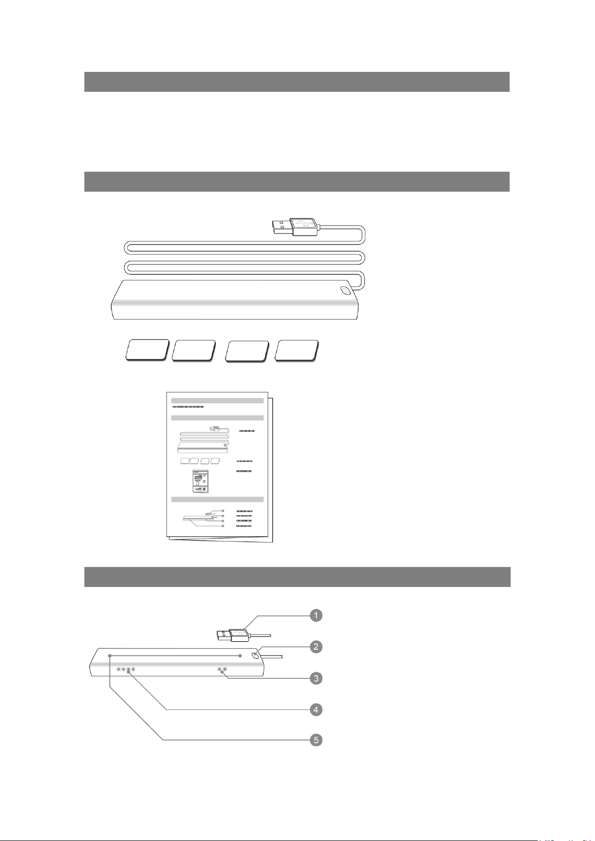
Content
Adamote
Fixation
Magnetic Brick
User Manual
X 1
X 4
X 1
Parts
USB Connector
Sync Button
Red-Blue Indicators
Status Indicators
IR Sensors
1
ADAMOTE-UM-ENG-0204
Operating Systems and Requirements
Adamote is standard USB Human Input Device (HID).
In mode A (mouse, keyboard, joystick), it supports:
➀
Windows XP or later versions.
➁
Mac OS 10.5 or later versions.
*
Due to Adamote is standard HID device, if a host supports USB HID, then
Adamote can be used in the host.
In mode B (emulator), it requires at least:
Windows XP SP2 or later versions.
Direct X 9 supporting.
Hardware: CPU AMD5000+ or upper.
Graphic Card: 8600GT or upper.
Dimension
Body
135 X 25 X 11 mm3
USB Line
650 mm
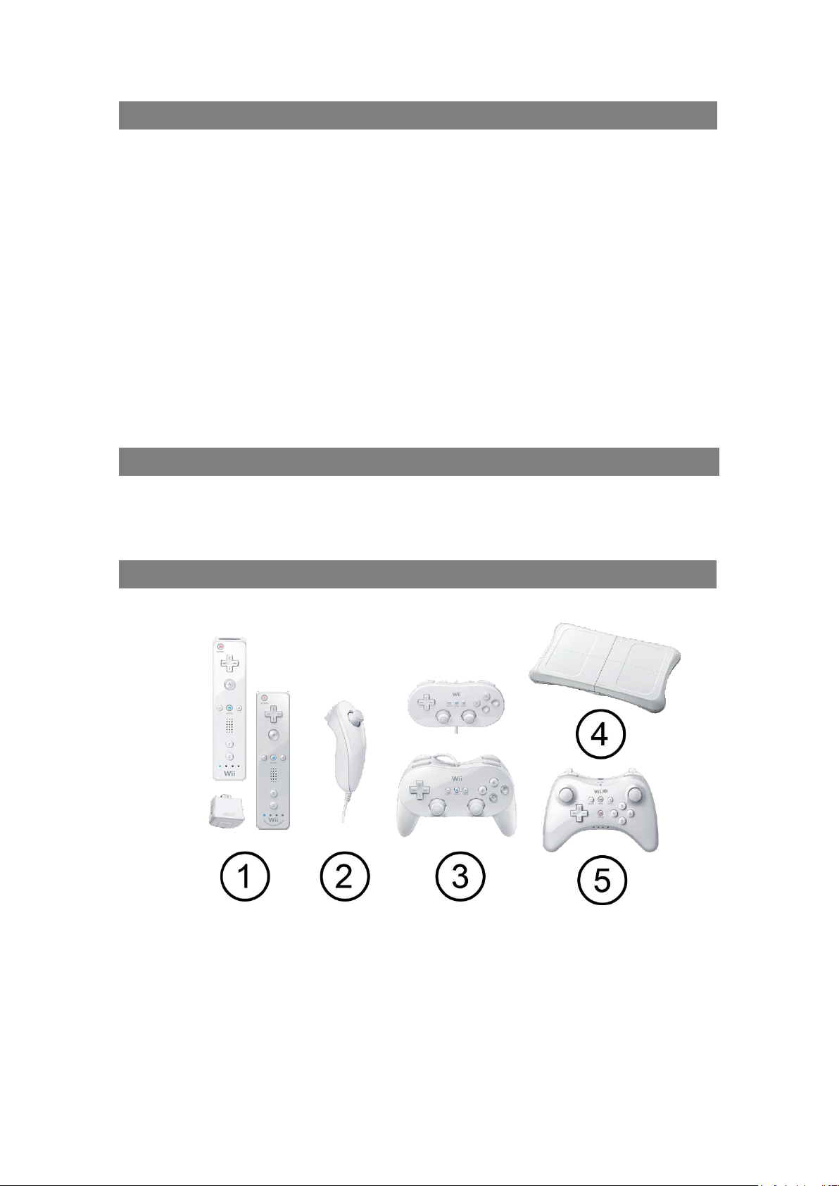
Supported Accessories
Adamote supports the following accessories:
➀
Wii Remotes, MotionPlus, and Wii Remote Plus (Built-In MotionPlus)
➁
Nunchuck
➂
Classic Controller and Class Controller Pro
④
Wii Balance Board (B mode)
⑤
Wii U Pro Controller (A mode)
* Wii, Wii U, Nunchuck, and MotionPlus are trademarks of Nintendo.
2
ADAMOTE-UM-ENG-0204
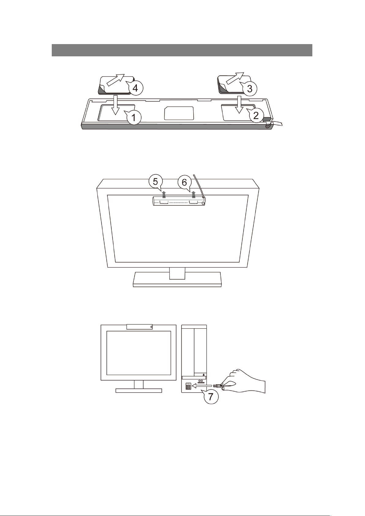
Installation
➀ ➁
Put the fixation bricks into the holes of the Adamote’s back.
➂ ➃
Tear off the white tapes of the magnetic bricks.
➄ ➅
Fix the Adamote on the top side of the screen.
➆
Plug in the USB connector to the PC.
3
ADAMOTE-UM-ENG-0204
Installation Locations
There are 3 possible installation locations:
➀
Locate it in the top side, and the sync button is at the right side.
➁
Locate it in the bottom side, and the sync button is at the left side.
➂
Locate it in the top of a notebook, and the sync button is at the right side.
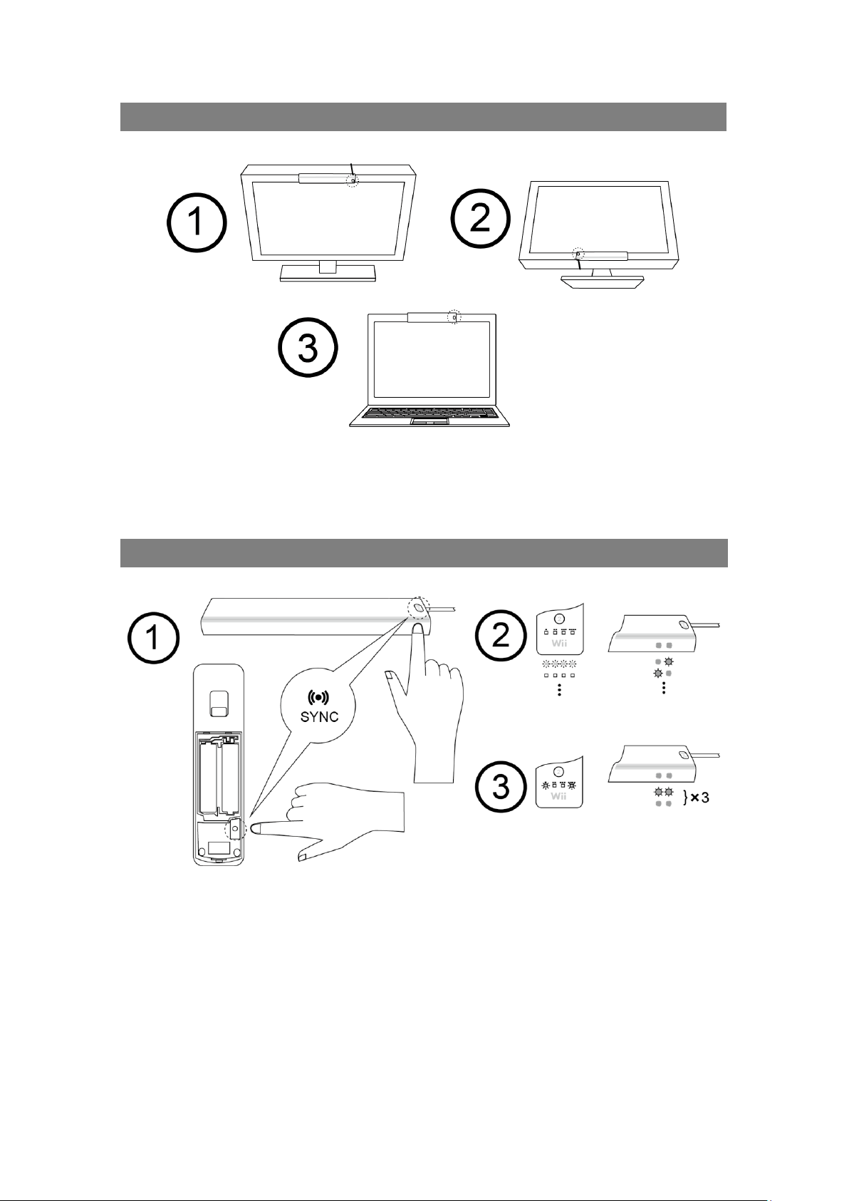
Pair Wii Remotes (Synchronizing Wii Remotes)
➀
Press the sync button of a Wii Remote, and the sync button of the
Adamote.
➁
All indicators of the Wii Remote start to flash. The red-blue indicators of
the Adamote are starting to flash repeatedly in an alternative way.
➂
After successful pairing (synchornization), the 1P indicator of the Wii
Remote lights up, and the red-blue indicators of the Adamote flash three
times.
*
Only need to pair once. In the next time to use, just press any button to
reconnect.
*
Use the same way to pair with Wii U Pro controllers.
4

ADAMOTE-UM-ENG-0204
A and B Modes
Ⓐ
In standard mode A, Adamote can connect up two Wii Remotes, and 1P
(■□□■) has the capability of mouse and keyboard. And 2P (□■□■) has the
capability of joystick.
Ⓑ
In the emulator mode B, there are up to 4 Wii Remotes to connect to
Adamote, and you can run the Akar emulator for Adamote to play backup
games. The indicators of Wii Remotes of mode B are 1P(■□□□),
2P(□■□□), 3P(□□■□) and 4P(□□□■).
*
Press the HOME button for 1 second to switch between mode A and B.
*
In mode A, only 1P can switch to mode B, and in mode B 1P to 4P can switch to
mode A.
5

ADAMOTE-UM-ENG-0204
Hybrid Cursor Positioning Technology
Hybrid Cursor Positioning Technology (HCP) will automatically switch IR cursor
positioning and MotionPlus positioning to calculate the cursor position.
➀
In the range of IR sensors, Adamote will use IR positioning to calculate the
position of the cursor. In this status, the red color of red-blue indicators will
light up.
➁
When the Wii Remote is out of the range of IR sensors, Adamote will
switch to MotionPlus positioning to calculate cursor position. In this status,
the red color of red-blue indicators will be turned off.
*
HCP Requires Wii Remote Plus or Wii Remote + MotionPlus.
*
HCP is patent pending.
IR Positioning in Mode A
➀
For better fluency experience of mouse cursor, please do the setting:
Start > Control Panel > Hardware > Mouse > Pointer Options > Enhance
pointer precision unchecked
➁
Please point forward from an Adamote.
➂
Make sure there is no obstacle between an Adamote and Wii Remotes.
6

ADAMOTE-UM-ENG-0204
Quick Overview of Feature Keys
Features in Mode A
Button Sequence
Reference
1
MotionPlus Calibration
Page 8
2
Cursor Range Adjusment
Page 9
3
Absolute / Relative
Mouse Cursor
Page 9
Page 10
4
Browser/Gaming Mode
Page 10
5
Default Key Mapping
Page 11
6
Customized Key Mapping
Page 11
7
Switch to 1P
Page 11
8
Switch to 2P
Page 11
Features in Mode A, B
9
Toggle A / B mode
Page 5
Function Key of the default key mapping in mode A
10
Function Key (Fn)
Page 7
Appendix
Function Key (Fn)
1
Each key mapping (default or customized) can have one function key (or
Fn key for short). In default key mapping, Fn is Button B.
2
When the function key (Fn) is pressed, the mouse cursor is frozen and
other buttons are altered to other key bindings.
3
For example, in default key mapping, Button A is “Mouse Left Button”, and
when Button B (Fn) is pressed then the button A becomes “Mouse Right
Button”.
7

ADAMOTE-UM-ENG-0204
MotionPlus Calibration in Mode A
Calibrate the MotionPlus of Wii Remotes if the cursor of MotionPlus
positioning is unstable:
➀
Click the HOME button. The Wii Remote’s 1P and 2P indicators light up.
➁
Press the Dpad’s Down button of the Wii remote.
➂
One of the status indicators is starting to flash repeatedly.
➃
Face down the Wii Remote on the desktop or ground around 2 seconds.
➄
The status indicator stops flashing when the calibration is done.
8

ADAMOTE-UM-ENG-0204
Cursor Range Adjustment in Mode A
➀
Click the HOME button. The Wii Remote’s 1P and 2P indicators light up.
➁
Press the Dpad’s left or right buttons of the Wii Remote to adjust cursor
ranges.
Indicators in Mode A
1
In mode A, the 1st indicator of status indicators will light up when 1P is
connected; the 2nd indicator of status indicators will light up when 2P is
connected.
2
When 1P is low-battery, the 1st indicator of status indicators will flash slowly
and repeatedly.
3
When 2P is low-battery, the 2nd indicator of status indicators will flash slowly
and repeatedly.
4
When a third-party Wii Remote is connected, the blue indicator of red-blue
indicators will flash repeatedly.
Absolute / Relative Mouse Cursor in Mode A
1
In the absolute mode, the mouse cursor will set to the same position when
it senses the same IR position. For example, it is suitable when you try to
use the mouse cursor to locate one target in the screen.
2
In the relative mode, the mouse cursor will do the relative motion only.
For example, it is suitable when your try to use mouse cursor to rotate
eyesight.
9

ADAMOTE-UM-ENG-0204
IR / HCP Mouse & Anti-Shake Switch in Mode A
➀
Click the HOME button. The Wii Remote’s 1P and 2P indicators light up.
The 3P indicator shows that mouse cursor is IR (led is on) or HCP (led is
off). The 4P indicator shows that it is in the anti-shake mode (led is on) or
in the normal mode (led is off).
➁
Then press the button 1 to switch mouse cursor to IR or HCP, and the
button 2 to switch to the anti-shake or the normal mode.
Key Mapping in Mode A
1
The default key mapping will change while a different accessory is
connected.
2
Please refer Appendix for the default key mapping.
Macro in Mode A
1
You can customize your own key mapping in mode A.
2
Detailed macro setting is available in our web site (Adamote Macro Setting
Software, or AMSS manual) http://akar.cc.
10

ADAMOTE-UM-ENG-0204
Toggle Key Mapping between Default and Macro
➀
Click the HOME button. The Wii Remote’s 1P and 2P indicators light up.
➁
Press the button ○– to switch to the default mapping, and the button ○+
to switch to the customized macro setting.
Switch 1P / 2P in Mode A
➀
Click the HOME button. The Wii Remote’s 1P and 2P indicators light up.
➁
Press the button○A to switch to 1P, and the button ○B to 2P.
11

ADAMOTE-UM-ENG-0204
Play Wii Games in Mode B
1
Please visit our official web site http://akar.cc for the latest Akar Emulator
to play in mode B.
2
Adamote fully supports the original Wii Remotes and most third-party
remotes. It will flash the blue indicator of red-blue indicators when a
third-party Remote is connected.
3
Due to the compatibility of third-party Remotes, Adamote might not work
properly if any third-party Remote is connected.
Appendix: Default Key Mapping of 1P Wii Remote
Normal (Function Key Released)
Function (Function Key Pressed)
* The complete default key mapping is available in the AMSS manual of http://akar.cc.
* Wii, Wii U, Nunchuck, and MotionPlus are trademarks of Nintendo.
12

ADAMOTE-UM-ENG-0204
FCC Warning
Changes or modifications to this unit not expressly approved by the party
responsible for compliance could void the user authority to operate the
equipment.
This device complies with Part 15 of the FCC Rules. Operation is subject to
the following two conditions: (1) this device may not cause harmful
interference, and (2) this device must accept any interference received,
including interference that may cause undesired operation.
The device has been evaluated to meet general RF exposure requirement.
The device can be used in portable exposure condition without restriction.
FCC Statement
This equipment has been tested and found to comply with the limits for a
Class B digital device, pursuant to Part 15 of the FCC Rules. These limits
are designed to provide reasonable protection against harmful interference
in a residential installation. This equipment generates, uses and can
radiate radio frequency energy and, if not installed and used in accordance
with the instructions, may cause harmful interference to radio
communications. However, there is no guarantee that interference will not
occur in a particular installation. If this equipment does cause harmful
interference to radio or television reception, which can be determined by
turning the equipment off and on, the user is encouraged to try to correct
the interference by one of the following measures:
Reorient or relocate the receiving antenna.
Increase the separation between the equipment and receiver.
Connect the equipment into an outlet on a circuit different from that to
which the receiver is connected.
Consult the dealer or an experienced radio/TV technician for help.
FCC warning statement
(15.21)
Warning: Changes or modifications to this unit not expressly approved by
the party responsible for compliance could void the user authority to
operate the equipment.
13
 Loading...