

Unigas HTP1030, HTP1080, HTP1050, TP1030, TP1050 Installation, User's, And Maintenance Manual
...Page 1

HTP1030
HTP1050
HTP1080
Gas - light oil
dual fuel burners
MANUAL OF INSTALLATION - USE - MAINTENANCE
BURNERS - BRUCIATORI - BRULERS - BRENNER - QUEMADORES -
M039180CC REV. 2 09/2009
ГОРЕЛКИ
Page 2

TABLE OF CONTENTS
WARNINGS ................................................................................................................................................................ 3
PART I: INSTALLATION 5
GENERAL FEATURES ................................................................................................................................................................... 5
Example of installation .................................................................................................................................................................... 6
How to choose the burner ............................................................................................................................................................... 7
Burner model identification ............................................................................................................................................................. 8
Country and usefulness gas categories .......................................................................................................................................... 8
Overall dimensions ......................................................................................................................................................................... 9
Performance curves ...................................................................................................................................................................... 10
Pressure in the network / gas rate curves ..................................................................................................................................... 11
INSTALLATION ............................................................................................................................................................................ 12
Packing ......................................................................................................................................................................................... 12
Handling the burner ...................................................................................................................................................................... 12
Fitting the burner to the boiler ....................................................................................................................................................... 12
Fan installation .............................................................................................................................................................................. 13
Matching the burner to the boiler .................................................................................................................................................. 13
GAS TRAIN CONNECTIONS ....................................................................................................................................................... 13
Assembling the gas grain .............................................................................................................................................................. 15
Siemens VGD20.. and VGD40.. gas valves - with SKP2.. (pressure governor) ......................................................................... 16
Pressure adjusting range .............................................................................................................................................................. 16
Hydraulic diagrams for light oil supplying circuits ......................................................................................................................... 18
Light oil piping installation diagram ............................................................................................................................................... 19
About the use of fuel pumps ......................................................................................................................................................... 19
Suntec TV Pressure governor ....................................................................................................................................................... 20
Assembling the light oil flexible hoses .......................................................................................................................................... 20
Connecting the burner to the light oil pumping unit ....................................................................................................................... 21
Electrical connections ................................................................................................................................................................... 21
Rotation of fan motor and pump motor ......................................................................................................................................... 21
ADJUSTMENTS ........................................................................................................................................................................... 22
Combustion head gas pressure curves depending on the flow rate ............................................................................................. 22
Measuring the gas pressure in the combustion head ................................................................................................................... 22
Pressure - rate in combustion head curves ................................................................................................................................. 23
Gas Filter ...................................................................................................................................................................................... 24
VPS504 Gas proving system ........................................................................................................................................................ 24
Adjusting the injector gas flow rate: Brahma EG12*R valve and pressure governor .................................................................... 24
Adjustments - brief description ...................................................................................................................................................... 25
Adjustment procedure ................................................................................................................................................................... 25
Calibration of air pressure switch.............................................................................................
Calibration of low gas pressure switch .......................................................................................................................................... 27
Adjusting the high gas pressure switch (when provided) .............................................................................................................. 28
PGCP Gas leakage pressure switch (witn SiemensLDU/Siemens LMV burner control).............................................................. 28
Fully modulating burners ............................................................................................................................................................... 28
Adjustment for light oil operation ................................................................................................................................................... 29
Oil circuit ....................................................................................................................................................................................... 33
..................................................... 27
PART II: OPERATION ............................................................................................................................................. 34
OPERATION ................................................................................................................................................................................. 35
PART III: MAINTENANCE ....................................................................................................................................... 36
ROUTINE MAINTENANCE ........................................................................................................................................................... 36
Gas filter maintenance .................................................................................................................................................................. 36
Replacing the spring in the gas valve group ................................................................................................................................. 37
Light oil filter maintenance ............................................................................................................................................................ 37
Removing the combustion head ................................................................................................................................................... 37
Adjusting the ignition electrode ..................................................................................................................................................... 38
Replacing the ignition electrode .................................................................................................................................................... 39
Cleaning and replacing the detection photocell ............................................................................................................................ 40
Seasonal stop ............................................................................................................................................................................... 40
TROUBLESHOOTING .................................................................................................................................................................. 41
SPARE PARTS ............................................................................................................................................................................. 42
APPENDIX
2
Page 3

WARNINGS
THIS MANUAL IS SUPPLIED AS AN INTEGRAL AND ESSENTIAL PART OF THE PRODUCT AND MUST BE DELIVERED TO THE
USER.
INFORMATION INCLUDED IN THIS SECTION ARE DEDICATED BOTH TO THE USER AND TO PERSONNEL FOLLOWING PRODUCT INSTALLATION AND MAINTENANCE.
THE USER WILL FIND FURTHER INFORMATION ABOUT OPERATING AND USE RESTRICTIONS, IN THE SECOND SECTION
OF THIS MANUAL. WE HIGHLY RECOMMEND TO READ IT.
CAREFULLY KEEP THIS MANUAL FOR FUTURE REFERENCE.
1) GENERAL INTRODUCTION
z The equipment must be installed in compliance with the regulations
in force, following the manufacturer’s instructions, by qualified personnel.
z Qualified personnel means those having technical knowledge in the
field of components for civil or industrial heating systems, sanitary
hot water generation and particularly service centres authorised by
the manufacturer.
z Improper installation may cause injury to people and animals, or
damage to property, for which the manufacturer cannot be held liable.
z Remove all packaging material and inspect the equipment for inte-
grity.
In case of any doubt, do not use the unit - contact the supplier.
The packaging materials (wooden crate, nails, fastening devices, plastic
bags, foamed polystyrene, etc), should not be left within the reach of children, as they may prove harmful.
z Before any cleaning or servicing operation, disconnect the unit from
the mains by turning the master switch OFF, and/or through the cut-
out devices that are provided.
z Make sure that inlet or exhaust grilles are unobstructed.
z In case of breakdown and/or defective unit operation, disconnect the
unit. Make no attempt to repair the unit or take any direct action.
Contact qualified personnel only.
Units shall be repaired exclusively by a servicing centre, duly authorised
by the manufacturer, with original spare parts.
Failure to comply with the above instructions is likely to impair the unit’s
safety.
To ensure equipment efficiency and proper operation, it is essential that
maintenance operations are performed by qualified personnel at regular
intervals, following the manufacturer’s instructions.
z When a decision is made to discontinue the use of the equipment,
those parts likely to constitute sources of danger shall be made har-
mless.
z In case the equipment is to be sold or transferred to another user, or
in case the original user should move and leave the unit behind,
make sure that these instructions accompany the equipment at all
times so that they can be consulted by the new owner and/or the
installer.
z For all the units that have been modified or have options fitted then
original accessory equipment only shall be used.
z This unit shall be employed exclusively for the use for which it is
meant. Any other use shall be considered as improper and, there-
fore, dangerous.
The manufacturer shall not be held liable, by agreement or otherwise, for
damages resulting from improper installation, use and failure to comply
with the instructions supplied by the manufacturer.
2) SPECIAL INSTRUCTIONS FOR BURNERS
z The burner should be installed in a suitable room, with ventilation
openings complying with the requirements of the regulations in force,
and sufficient for good combustion.
z Only burners designed according to the regulations in force should
be used.
z This burner should be employed exclusively for the use for which it
was designed.
z Before connecting the burner, make sure that the unit rating is the
same as delivery mains (electricity, gas oil, or other fuel).
z Observe caution with hot burner components. These are, usually,
near to the flame and the fuel pre-heating system, they become hot
during the unit operation and will remain hot for some time after the
burner has stopped.
When the decision is made to discontinue the use of the burner, the user
shall have qualified personnel carry out the following operations:
a Remove the power supply by disconnecting the power cord from the
mains.
b) Disconnect the fuel supply by means of the hand-operated shut-off
valve and remove the control handwheels from their spindles.
Special warnings
z Make sure that the burner has, on installation, been firmly secured to
the appliance, so that the flame is generated inside the appliance
firebox.
z Before the burner is started and, thereafter, at least once a year,
have qualified personnel perform the following operations:
a set the burner fuel flow rate depending on the heat input of the
appliance;
b set the flow rate of the combustion-supporting air to obtain a combu-
stion efficiency level at least equal to the lower level required by the
regulations in force;
c check the unit operation for proper combustion, to avoid any harmful
or polluting unburnt gases in excess of the limits permitted by the
regulations in force;
d make sure that control and safety devices are operating properly;
e make sure that exhaust ducts intended to discharge the products of
combustion are operating properly;
f on completion of setting and adjustment operations, make sure that
all mechanical locking devices of controls have been duly tightened;
g make sure that a copy of the burner use and maintenance instruc-
tions is available in the boiler room.
z In case of a burner shut-down, reser the control box by means of the
RESET pushbutton. If a second shut-down takes place, call the
Technical Service, without trying to RESET further.
z The unit shall be operated and serviced by qualified personnel only,
in compliance with the regulations in force.
3) GENERAL INSTRUCTIONS DEPENDING ON FUEL USED
3a) ELECTRICAL CONNECTION
z For safety reasons the unit must be efficiently earthed and installed
as required by current safety regulations.
z It is vital that all saftey requirements are met. In case of any doubt,
ask for an accurate inspection of electrics by qualified personnel,
since the manufacturer cannot be held liable for damages that may
be caused by failure to correctly earth the equipment.
z Qualified personnel must inspect the system to make sure that it is
adequate to take the maximum power used by the equipment shown
on the equipment rating plate. In particular, make sure that the
system cable cross section is adequate for the power absorbed by
the unit.
z No adaptors, multiple outlet sockets and/or extension cables are per-
mitted to connect the unit to the electric mains.
z An omnipolar switch shall be provided for connection to mains, as
required by the current safety regulations.
z The use of any power-operated component implies observance of a
few basic rules, for example:
- do not touch the unit with wet or damp parts of the body and/or with
bare feet;
- do not pull electric cables;
- do not leave the equipment exposed to weather (rain, sun, etc.)
unless expressly required to do so;
- do not allow children or inexperienced persons to use equipment;
z The unit input cable shall not be replaced by the user.
In case of damage to the cable, switch off the unit and contact qualified
personnel to replace.
When the unit is out of use for some time the electric switch supplying all
the power-driven components in the system (i.e. pumps, burner, etc.)
should be switched off.
3
Page 4

3b) FIRING WITH GAS, LIGHT OIL OR OTHER FUELS
GENERAL
z The burner shall be installed by qualified personnel and in com-
pliance with regulations and provisions in force; wrong installation
can cause injuries to people and animals, or damage to property, for
which the manufacturer cannot be held liable.
z Before installation, it is recommended that all the fuel supply system
pipes be carefully cleaned inside, to remove foreign matter that might
impair the burner operation.
z Before the burner is commissioned, qualified personnel should ins-
pect the following:
a the fuel supply system, for proper sealing;
b the fuel flow rate, to make sure that it has been set based on the
firing rate required of the burner;
c the burner firing system, to make sure that it is supplied for the desi-
gned fuel type;
d the fuel supply pressure, to make sure that it is included in the range
shown on the rating plate;
e the fuel supply system, to make sure that the system dimensions are
adequate to the burner firing rate, and that the system is equipped
with all the safety and control devices required by the regulations in
force.
z When the burner is to remain idle for some time, the fuel supply tap
or taps should be closed.
SPECIAL INSTRUCTIONS FOR USING GAS
Have qualified personnel inspect the installation to ensure that:
a the gas delivery line and train are in compliance with the regulations
and provisions in force;
b all gas connections are tight;
c the boiler room ventilation openings are such that they ensure the air
supply flow required by the current regulations, and in any case are
sufficient for proper combustion.
z Do not use gas pipes to earth electrical equipment.
z Never leave the burner connected when not in use. Always shut the
gas valve off.
z In case of prolonged absence of the user, the main gas delivery
valve to the burner should be shut off.
Precautions if you can smell gas
a do not operate electric switches, the telephone, or any other item
likely to generate sparks;
b immediately open doors and windows to create an air flow to purge
the room;
c close the gas valves;
d contact qualified personnel.
z Do not obstruct the ventilation openings of the room where gas
appliances are installed, to avoid dangerous conditions such as the
development of toxic or explosive mixtures.
DIRECTIVES AND STANDARDS
Gas burners
European directives:
- Directive 90/396/CEE - Gas Appliances;
- Directive 2006/95/EC on low voltage;
- Directive 2004/108/CEE on electromagnetic compatibility
Harmonised standards :
-UNI EN 676 (Gas Burners;
-CEI EN 60335-1(Household and similar electrical appliances - Safety.
Part 1: General requirements;
- EN 50165 (Electrical equipment of non-electric appliances for household and similar purposes. Safety requirements.
Light oil burners
European directives:
- Directive 2006/95/EC on low voltage;
-
Directive 2004/108/CEE on electromagnetic compatibility
Harmonised standards :
-CEI EN 60335-1(Household and similar electrical appliances - Safety.
Part 1: General requirements;
- EN 50165 (Electrical equipment of non-electric appliances for household and similar purposes. Safety requirements.
National standards :
-UNI 7824: Monobloc nebulizer burners for liquid fuels. Characteristics
and test methods
Heavy oil burners
European directives:
- Directive 2006/95/EC on low voltage;
- Directive 2004/108/CEE on electromagnetic compatibility
Harmonised standards :
-CEI EN 60335-1 Household and similar electrical appliances - SafetyPart
1: General requirements;
- EN 50165 Electrical equipment of non-electric appliances for household
and similar purposes. Safety requirements.
National standards :
-UNI 7824: Monobloc nebulizer burners for liquid fuels. Characteristics
and test methods
Gas - Light oil burners
European directives:
- Directive 90/396/CEE Gas Appliances;
- Directive 2006/95/EC on low voltage;
- Directive 2004/108/CEE on electromagnetic compatibility
Harmonised standards :
-UNI EN 676 Gas Burners
-CEI EN 60335-1(Household and similar electrical appliances - Safety.
Part 1: General requirements;
- EN 50165 Electrical equipment of non-electric appliances for household
and similar purposes. Safety requirements.
National standards :
-UNI 7824: Monobloc nebulizer burners for liquid fuels. Characteristics
and test methods
Gas - Heavy oil burners
European directives:
- Directive 90/396/CEE - Gas Appliances;
- Directive 2006/95/EC on low voltage;
- Directive 2004/108/CEE on electromagnetic compatibility
Harmonised standards :
-UNI EN 676 (Gas Burners;
-CEI EN 60335-1(Household and similar electrical appliances - Safety.
Part 1: General requirements;
- EN 50165 Electrical equipment of non-electric appliances for household
and similar purposes. Safety requirements.
National standards :
-UNI 7824: Monobloc nebulizer burners for liquid fuels. Characteristics
and test methods
4
Page 5

CIB UNIGAS - M039180CC
PART I: INSTALLATION
GENERAL FEATURES
This series of industrial burners is designed for all those applications that require big-sized air fans or air-flue heat exchangers to be
installed in sound-proof areas to reduce noise. They can be provided with built-in or separately-mounted control panel (console or wallmounted).
10
9
8
7
11
12
6
5
1
2
4
Fig. 1
1 Adjusting cam
2 Actuator
3 Bellows
4 Air inlet flange
5 Junction box
6 Combustion head adjusting screw
7 Gas filter
8 Gas valves group
9 Cover
10 Ignitor gas train
11 Combustion head-blast tube ass.y
12 Burner flange
Gas operation: the gas coming from the supply line, passes through the valves group provided with filter and stabiliser. This one for-
ces the pressure in the utilisation limits. The actuator (2) moves proportionally the air damper and the gas butterfly valve It drives an
adjusting cam (1) with variable shape. This one allows the optimisation of the gas flue values, as to get an efficient combustion.
Light oil operation:the fuel coming from the supply line, is pushed by the pump to the nozzle and then into the combustion chamber,
where the mixture between fuel and air takes place and consequently the flame.
In the burners, the mixture bertween fuel and air, to perform clean and efficient combustion, is activated by atomisation of oil into very
small particles. This process is achieved making pressurised oil passing through the nozzle.
The pump (8) main function is to transfer oil from the tank to the nozzle in the desired quantity and pressure. To adjust this pressure,
pumps are provided with a pressure regulator (except for some models for which a separate regulating valve is provided). Other pumps
are provided with two pressure regulators: one for the high and one for low pressure (in double-stage systems with one nozzle).
The adjustable combustion head can improve the burner performance. The combustion head (11) determines the energetic quality and
the geometry of the flame. Fuel and comburent are routed into separated ways as far as the zone of flame generation (combustion
chamber).
3
5
Page 6

Example of installation
CIB UNIGAS - M039180CC
Burner
Gas train
Pumping unit
Fan
Electric panel
Note: the picture shows one of the possible installations. Fan, electrical panel and pumping unit can be placed according to the customer needs.
6
Page 7

CIB UNIGAS - M039180CC
How to choose the burner
To check if the burner is suitable for the boiler to which it must be installled, the following parameters are needed:
z fuel
z furnace input, in kW or kcal/h (kW = kcal/h / 860);
z boiler type;
z combustione head type (reverse flame or three phase)’
z temperature or pressure of the thermal carrier fluid
z Comburent air temperature
z Air duct positioning
z Pressure in the combustion chamber
z Elevation (altitude) of burner installation
z Gas train (only for gas burners)
z Pumping unit (only for light-oil or heavy-oil burners)
z Air fan
z Bilt-in or separated control panel
z backpressure (data are available on the boiler’s ID plate or in the user’s manual).
Burners provided with built-in control panel are designed for IP40 index of protection. For other values of IP, please contact the manifacturer Technical Dpt.
Data requested:
z furnace input;
Power output diagram at 15àC air temperature
TP1050
TP1030
TP525A
TP520A
TP515A
TP512A
TP93A
TP92A
TP91A
TP90A
0 2000 4000 6000 8000 10000 12000 14000 16000
Burner performance range
z air temperature
z altitude
z generator pressure or temperature
Example:
z furnace input: 9600kW
z air temperature: 15°C
z altitude: 0m
Fig. 2
See the diagram in Fig. 2, as to find the burners that better suite the power range requested in the exmple (9600kW). Once the models
are founded out, the choice regards technical and economical features. Technical features can be summarised in a higher modulation
ratio (fewer start-ups, less consumption, fewer swigings in the generator temperature and pressure values.
Checking the proper gas train size
To check the proper gas train size, it is necessary to know the available gas pressure value upstream the burner’s gas valve. Then
subtract the backpressure. The result is called pgas. Draw a vertical line matching the furnace input value (600kW, in the example),
quoted on the x-axis, as far as intercepitng the network pressure curve, according to the installed gas train (DN65, in the example).
From the interception point, draw an horizontal line as far as matching, on the y-axis, the value of pressure necessary to get the requested furnace input. This value must be lower or equal to the p
Tipo / Type P6 0
M-. ..50 ( Multib loc DUNGS MB- DLE 420 B01)
M-...65 (Filtro / Filter DN65+ SIEMENS VGD40.065 +SKP1x+SKP2x)
25
20
15
10
pressure (mbar)
5
rete / Minimum inlet gas
Minima pressione gas in
0
100 200 300 400 500 600 700 80 0 900
gas value, calculated before.
Rp 2" (50)
DN65
Fig. 3
Potenza / Output (kW)
7
Page 8

CIB UNIGAS - M039180CC
Burner model identification
Burners are identified by burner type and model. Burner model identification is described as follows.
Type HTP1030 Model M-. PR. S. *. A. 1. 80
(1) (2) (3) (4) (5) (6) (7) (8)
(1) BURNER TYPE HTP1030 - HTP1050 - HTP1080
(2) FUEL MG - Natural gas-light oil
(3) OPERATION Available versions PR - Progressive MD - Fully modulating
(4) BLAST TUBE S - Standard
(5) DESTINATION COUNTRY
* - see data plate
(6) BURNER VERSION A - StandardY - Special
(7) EQUIPMENT 1 = 2 valves + gas proving system
8 = 2 valves + gas proving system + high gas pressure switch
(8) GAS CONNECTION 80 = DN80 100 = DN100 125 = DN125
Technical specifications
BURNER TYPE
Output
Fuel
Gas category (see next paragraph)
Gas rate
Oil Density
Oil Viscosity
Light oil rate
Power supply
Total power consumption
Total power consumption
Protection
Operation
Gas pressure (see Note 2)
Gas train 80
Gas train 100
Gas train 125
Weight
Operating temperature °C
Storage Temperature °C
Working service*
Note1:
Note2: Maximum gas pressure = 500mbar (with Siemens VGD gas valves).
all gas flow rates are referred to Stm
ral gas (nett calorific value H
Minimum gas pressure = see gas curves.
= 34.02 MJ/Stm3).
i
min - max kW
3
min.- max.(Stm
min.-max. kg/h
kW
kW
Ø
Valves Connection
Valves Connection
Ø
Valves Connection
Ø
3
/h (1013 mbar absolute pressure, 15 °C temperature) and are valid for G20 natu-
/h)
kg
*NOTE ON THE BURNER WORKING SERVICE: for safety reasons, one controlled shutdown must be performed every 24 hours of
continuous operation.
HTP1030 HTP1050 HTP1080
2550-13000 3500-15500 4500-19000
Natural gas-light oil
270-1376 370-1641 476-2010
840 kg/m3
2 - 7.4 cSt@ 40°C
215 - 1095 295 - 1306 380 - 1600
400V 3N~ 50
5.5
6
IP40
Progressive - Fully modulating
80 / DN80
100 / DN100
125 / DN125
300
-10 ÷ +50
-20 ÷ +60
Internittent
Country and usefulness gas categories
GAS
CATEGORY
I
2H
I
2E
I
2E( R ) B
I
2L
I
2ELL
I
2Er
COUNTRY
AT ES GR SE FI IE HU IS NO CZ DK GB IT PT CY EE LV SI MT SK BG LT RO TR CH
LUPL-----------------------
BE------------------------
NL------------------------
DE------------------------
FR------------------------
8
Page 9

Overall dimensions (mm)
9
CIB UNIGAS - M039180CC
Air inlet flange
DN A B C CC D E F G H J JJ K KK L M N O OO P Q R RR S SS TT U V W Y Z
HTP1030 80 1864 544 1320 348 1898 1301 597 464 504 710 185 660 660 845 M16 651 460 1000 460 936 200 265 736 80 587 1092 322 1175 372 330
HTP1030 100 1864 544 1320 348 1914 1317 597 464 504 710 185 660 660 845 M16 651 460 1000 460 842 200 265 642 80 587 1092 382 1175 372 330
HTP1050 80 1864 544 1320 348 1898 1301 597 489 539 710 185 660 660 845 M16 651 460 1000 460 936 200 265 736 80 587 1092 322 1175 408 330
HTP1050 100 1864 544 1320 348 1914 1317 597 489 539 710 185 660 660 845 M16 651 460 1000 460 842 200 265 642 80 587 1092 382 1175 408 330
HTP1080 100 1864 544 1320 348 1914 1317 597 514 564 710 185 660 660 845 M16 651 460 1000 460 842 200 265 642 80 587 1092 382 1175 408 330
HTP1080 125 1864 544 1320 348 1946 1349 597 514 564 710 185 660 660 845 M16 651 460 1000 460 954 200 265 754 80 587 1192 480 1175 408 330
Boiler recommended drilling jig
Burner flange
Page 10

Performance curves
HTP1030
CIB UNIGAS - M039180CC
2000 4000 6000 8000 10000 12000 14000
HTP1050
2000 4000 6000 8000 10000 12000 14000 16000
HTP1080
kW
kW
4000 6000 8000 10000 12000 14000 16000 18000 20000
Performance range
To get the input in kcal/h, multiply value in kW by 860.
Data are referred to standard conditions: 1013mbar, 15°C.
10
kW
Page 11

Pressure in the network / gas rate curves
HTP1030
450
400
350
300
250
200
15 0
10 0
GAS PRESSURE IN
THE NETWORK mbar
HTP1050
50
0
200 300 400 500 600 700 800 900 1000 1100 1200 1300 1400
CIB UNIGAS - M039180CC
DN80
DN100
DN125
Gas rate Stm3/h
500
400
300
200
GAS PRESSURE IN
THE NETWORK mbar
10 0
0
300 400 500 600 700 800 900 1000 1100 1200 1300 1400 1500 1600 1700
HTP1080
450
400
350
300
250
200
15 0
GAS PRESSURE IN
THE NETWORK mbar
10 0
50
0
400 500 600 700 800 900 1000 1100 1200 1300 1400 1500 1600 1700 1800 1900 2000 2100 2200
DN80
DN100
DN125
Gas rate Stm3/h
DN100
DN125
Gas rate Stm3/h
Caution: the gas rate value is quoted on the x-axis, the related network pressure is quoted on the y-axis (pressure value in
the combustion chamber is not included). To know the minimum pressure at the gas train inlet, necessary to get the requested gas rate, add the pressure value in the combustion chamber to the value read on the y-axis.
11
Page 12

CIB UNIGAS - M039180CC
INSTALLATION
Packing
The burners are despatched in wodden crates whose dimensions are:
HTP1030 - HTP1050: 2180 mm x 1180 mm x 1210 mm (L x P x H)
HTP1080: 2180 mm x 1580 mm x 1560 mm (L x P x H)
Packing cases of this type are affected by humidity and are not suitable for stacking.
In each packing case, find:
1 burner with gas train detached;
1 gasket to be inserted between the burner and the boiler;
2 flexible oil pipes;
1 oil filter;
1 envelope containing this manual
To get rid of the burner’s packing, follow the procedures laid down by current laws on disposal of materials.
H
P
Handling the burner
ATTENTION! Handling operations must be performed by trained personnel specialised on handling loads. If these
operations are not carried out correctly, the residual risk for the machine to overturn and fall down remains.
To handle the machine, use means suitable to handle requested loads (see par. “Technical specifications”).”
The burner is provided with eye-bolts for lifting.
Eye-bolts
L
Fitting the burner to the boiler
1 To perform the installation, it is necessary to drill the boiler door as described on paragraph “Overall dimensions”;
2 screw the studbolts (5) on the boiler door, according to the drilling plate (see paragraph “Overall dimensions”);
3 move the burner towards the boiler: lift the burner by means of the eyebolts placed on its top side;
4 remove the balst tube, by loosening the three screws beside the burner flange;
5 place the the ceramic fibre plait on the burner flange;
6 replace the blast tube: before fastening completely the screws, avoid any misalignement between the blast tube axis and the com-
bustion head axis;
7 install the burner to the boiler;
8 fix the burner to the stud bolts, by means of the fixing nuts, according to Fig. 4.
9 After fitting the burner to the boiler, ensure that the gap between the blast tube and the refractory lining is sealed with appropriate
insulating material (ceramic fibre cord or refractory cement).
12
Page 13

CIB UNIGAS - M039180CC
Keys
4
1Burner
2 Fixing nut
7
3 Washer
4 Ceramic fibre plait
5 Stud bolt
7Blast tube
Fig. 4
Fan installation
Pay attention when designing the air duct: dimensioning must be performed according to the flow rate, the temperature, the distance
between the fan and the burner and according to the fan features as well.
ATTENTION! The bellows unit provided is made of canvas and is provided with blocking spacers to avoid breaking it during
installation: first place the bellows unit between flanges, then remove the spacers. Canvas has to be stretched after the installation, but not stressed.
Matching the burner to the boiler
To correctly match the burner to the boiler verify the necessary input and the pressure in combustion chamber are included in the burner performance curve; otherwise the choice of the burner must be revised consulting the burner manufacturer.
To choose the blast tube lenght follow the instructions of the boiler manufacturer. In absence of these consider the following:
z Cast-iron boilers, three pass flue boilers (with the first pass in the rear part): the blast tube must protrude no more than 100 mm into
the combustion chamber.
z Pressurised boilers with flame reversal: in this case the blast tube must penetrate at least 50 - 100 mm into combustion chamber in
respect to the tube bundle plate.
The length of the blast tubes does not always allow this requirement to be met, and thus it may be necessary to use a suitably-sized
spacer to move the burner backwards.
GAS TRAIN CONNECTIONS
The diagrams show the components of the gas trai included in the delivery and which must be fitted by the installer.The diagrams are in
compliance with the current laws.
ATTENTION: BEFORE EXECUTING THE CONNECTIONS TO THE GAS PIPE NETWORK, BE SURE THAT THE
MANUAL CUTOFF VALVES ARE CLOSED.
Gas train - 1 (DN80/100): Gas train with valves group VGD40 with built-in gas pressure governor + VPS504 gas proving
system
4
MANUFACTURER
45
INSTALLER
1
2
678
11
5
3
14
15 15
78
13
Page 14

CIB UNIGAS - M039180CC
Gas train 2 (DN80/100): Gas train with valves group MBC 1900/3100/5000SE (2 valves + gas filter + pressure governor +
pressure switch) + LDU gas proving system
MANUFACTURER
INSTALLER
4
19
45
1
2
5
6
14
7
8
3
7
8
15 15
Key
1 Burner
2 Butterfly valve
3 Gas proving system
4 High gas pressure switch (option*)
5 Low gas pressure switch
8 Manual cutoff valve
11 VGD Valves group
14 Pressure governor with filter
15 Ignitor gas valve
19 MBC Valves group (DN80/100)
6 Gas filter
7 Bellow joint
Gas train - 3: Gas train with valves group VGD 40 with built-in gas pressure governor + gas leakage pressure switch (PGCP)
for Siemens LDU/LMV burner control
MANUFACTURER
4
1
2
16
45
6
INSTALLER
7
8
11
5
15 15
14
78
Key
1 Burner
2 Butterfly valve
4 High gas pressure switch (option*)
5 Low gas pressure switch
6 Gas filter
8 Manual cutoff valve
11 VGD Valves group
14 Pressure governor with filter
15 Ignitor gas valve
16 PGCP (leakage control pressure switch)
7 Bellow joint
* Note: the high gas pressure switch can be mounted either upstream the gas valve or downstream the gas valves but upstream the
butterfly gas valve.
14
Page 15

CIB UNIGAS - M039180CC
The pilot gas train is already installed to the burner, the following connections must be executed:
z connection from the filter with stabiliser to the gas supply network
z connection from the valve to the main gas train, by means of the pipe provided with the burner.
connection from the pilot gas train to the gas valves
group of the main train
connection to the gas supply network
3
SIEMENS VGD40..
Fig. 5 - pipe port (3) for connecting the pilot gas train to the valves group of the main gas train
-
Assembling the gas grain
To assemble the main gas train, proceed as follows:
”direction” arrows for installation
3
1E
21D
DUNGS MBC3100-5000SE
gas supply network
1A
5
1B
Keys
1A..1E Gasket
4
1C
2 Gas filter
3 Gas valves group
4 Bellow joint
5 Manual cock
Fig. 6 - Example of gas train
1) in case of flanged joints: place a gasket (no. 1A..1E - Fig. 6) between the elements
2) fasten all the items by means of screws, according to the shcemes showed before, obesrving the mounting direction for each
item.
15
Page 16

CIB UNIGAS - M039180CC
NOTE: the bellow joint, the manual valve and the gaskets are not part of the standard supply.
ATTENTION: once the gas train is mounted according to the diagram on Fig. 6, the gas proving test mus be performed,
according to the procedure set by the laws in force.
The procedures of installation fo the gas valves are showed in the next paragraphs, according to the gas train used:
z flanged gas trains with Multibloc Dungs MBC..SE 1900-3100-5000 or Siemens VGD40.. (flanged valves group)
Siemens VGD20.. and VGD40.. gas valves - with SKP2.. (pressure governor)
Mounting
z When mounting the VGD.. double gas valve, two flanges are required (as for VGD20.. model, the flanges are threaded);
z to prevent cuttings from falling inside the valve, first fit the flanges to the piping and then clean the associated parts;
z install the valve;
z the direction of gas flow must be in accordance with the direction of the arrow on the valve body;
z ensure that the bolts on the flanges are properly tightened;
z ensure that the connections with all components are tight;
z make certain that the O-rings and gaskets between the flanges and the double gas valve are fitted.
z
Connect the reference gas pipe (TP in figure), to the gas pressure nipples placed on the gas pipe, downstream the gas valves: gas pressure must be measured at a distance that must be at least 5 times the pipe size .
Leave the blowhole free (SA in figure). Should the spring fitted not permit satisfactory regulation, ask one of our service centres for a
suitable replacement.
WARNING: removing the four screws BS causes the device to be unserviceable!
SIEMENS VGD..MOUNTING
POSITIONS
BS
BS
SKP1. SKP2.
BS
BS
SA
TP
Fig. 7
Fig. 8
MULTIBLOCDUNGS MBC1900-3100-5000SE (Flanged valves group)
Mounting
1. Insert setscrews A
2. Insert seals
3. Insert setscrews B
4. Tighten setscrews A + B.
Ensure correct seating of the seal!
6. After installation, perform leakage and functional test.
7. Disassembly in reverse order.
Mounting positions OPTION
njo/!6!y!EO
2
10 = pulse lines
21
22
7631z05/0101
Fig. 9
#
#
#
"
"
EO
Fig. 10
#
"
"
Pressure adjusting range
The pressure adjusting range, downstream the gas valves group, changes according to the spring provided with the valve group.
16
Page 17
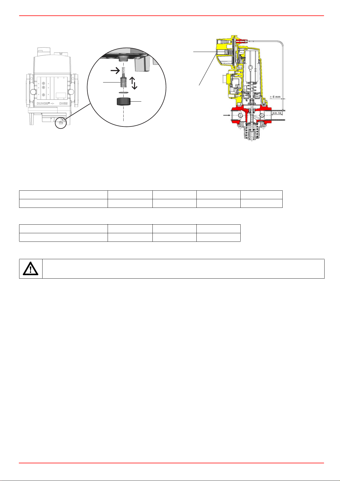
Keys
1 spring
2 cap
CIB UNIGAS - M039180CC
1
1
2
2
DUNGS MBC..SE Siemens SKP actuator
DUNGS MBC valves:
Performance range (mbar) 4 - 20 20 - 40 40 - 80 80 - 150
Spring colour - red black green
Siemens VGD valves with SKP actuator:
Performance range (mbar) 0 - 22 15 - 120 100 - 250
Spring colour neutral yellow red
Once the train is installed, electrically connect all its elements: gas valves group, pressure switches, gas proving system.
ATTENTION: once the gas train is mounted according to the diagram on Fig. 6, the gas proving test mus be performed,
according to the procedure set by the laws in force.
17
Page 18
CIB UNIGAS - M039180CC
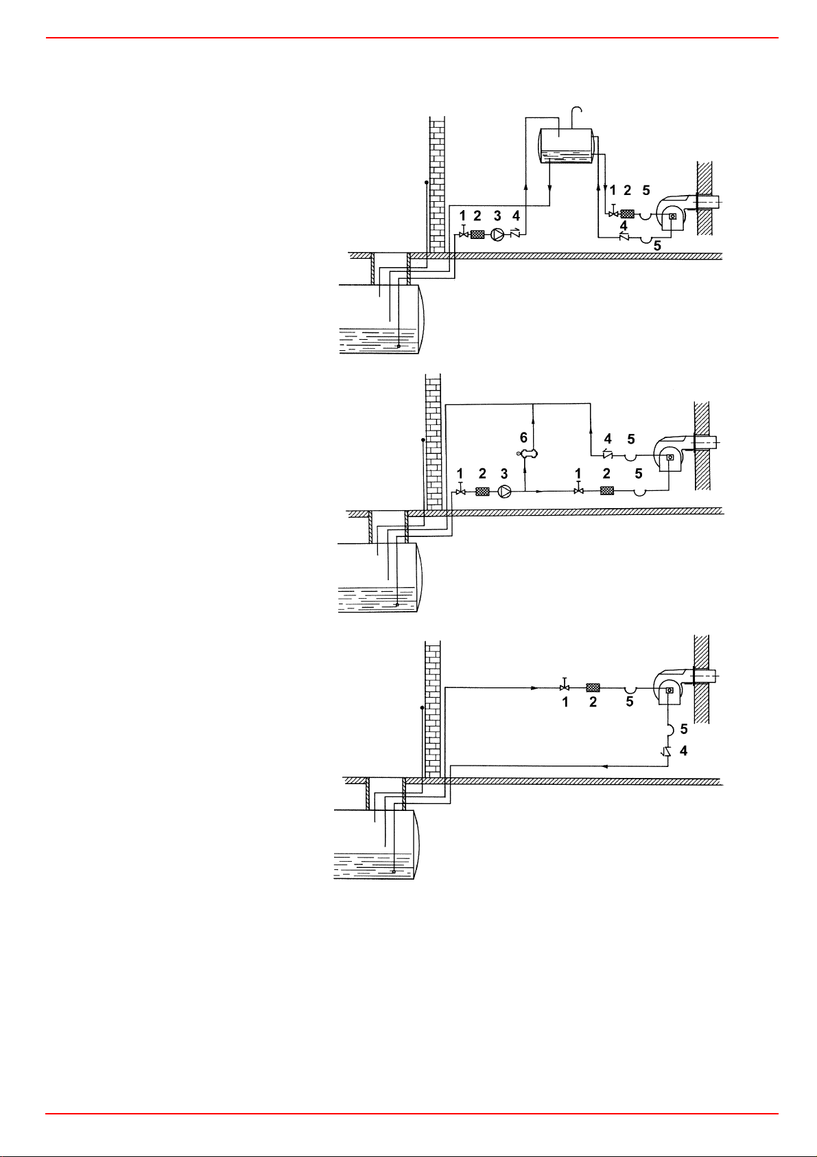
Hydraulic diagrams for light oil supplying circuits
Fig. 11 - Gravity circuit
Fig. 12 - Ring circuit
Fig. 13 - Suction circuit
Key
1 Manual valve
2 Light oil filter
3 Light oil feeding pump
4 One way valve
5 Flexible hoses
6 Relief valve
NOTE: in plants where gravity or ring feed systems are provided, install an automatic interception device (see n. 4 - Fig. 14).
18
Page 19
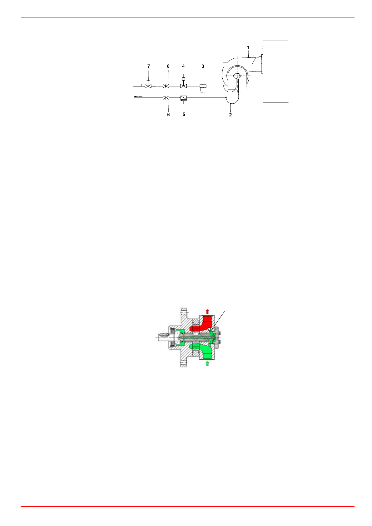
Light oil piping installation diagram
From tank
To tank
CIB UNIGAS - M039180CC
Fig. 14
Key
1 Burner
2 Flexible hoses (fitted)
3 Light oil filter (fitted)
4 Automatic interceptor (*)
5 One-way valve (*)
(*) Only for installations with gravity, siphon or forced circulation feed systems. If the device installed
is a solenoid valve, a timer must be installed to
delay the valve closing.
The direct connection of the device without a timer
may cause pump breaks.
6 Gate valve
7 Quick-closing gate-valve (not in vicinity of tank or boiler)
The pumps that are used can be installed both into single-pipe and double-pipe systems.
Single-pipe system: a single pipe drives the oil from the tank to the pump’s inlet. Then, from the pump, the pressurised oil is driven to
the nozzle: a part comes out from the nozzle while the othe part goes back to the pump. In this system, the by-pass pulg, if provided,
must be removed and the optional return port, on the pump’s body, must be sealed by steel plug and washer.
Double-pipe system: as for the single pipe system, a pipe that connects the tank to the pump’s inlet is used besides another pipe that
connects the pum’s return port to the tank, as well. The excess of oil goes back to the tank: this installation can be considered self-bleeding. If provided, the inside by-pass plug must be installed to avoid air and fuel passing through the pump.
Burners come out from the factory provided for double-stage systems. They can be suited for single-pipe system (recommended in the
case of gravity feed) as decribed before.To change from a 1-pipe system to a 2-pipe-system, insert the by-pass plug G (as for ccw-rotation- referring to the pump shaft).
Caution: Changing the direction of rotation, all connections on top and side are reversed.
pipeline length in meters.
Suntec T
G
Bleed
Bleeding in two-pipe operation is automatic : it is assured by a bleed flat on the piston. In one-pipe operation, the plug of a pressure
gauge port must be loosened until the air is evacuated from the system.
About the use of fuel pumps
z Make sure that the by-pass plug is not used in a single pipe installation, because the fuel unit will not function properly and damage
to the pump and burner motor could result.
z Do not use fuel with additives to avoid the possible formation over time of compounds which may deposit between the gear teeth,
thus obstructing them.
z After filling the tank, wait before starting the burner. This will give any suspended impurities time to deposit on the bottom of the
tank, thus avoiding the possibility that they might be sucked into the pump.
z On initial commissioning a "dry" operation is foreseen for a considerable length of time (for example, when there is a long suction
line to bleed). To avoid damages inject some lubrication oil into the vacuum inlet.
z Care must be taken when installing the pump not to force the pump shaft along its axis or laterally to avoid excessive wear on the
joint, noise and overloading the gears.
z Pipes should not contain air pockets. Rapid attachment joint should therefore be avoided and threaded or mechanical seal junc-
tions preferred. Junction threads, elbow joints and couplings should be sealed with removable sg component. The number of junctions should be kept to a minimum as they are a possible source of leakage.
19
Page 20
CIB UNIGAS - M039180CC
z
Do not use PTFE tape on the suction and return line pipes to avoid the possibility that particles enter circulation. These could deposit on the pump filter or the nozzle, reducing efficiency. Always use O-Rings or mechanical seal (copper or aluminium gaskets) junctions if possible.
z An external filter should always be installed in the suction line upstream of the fuel unit.
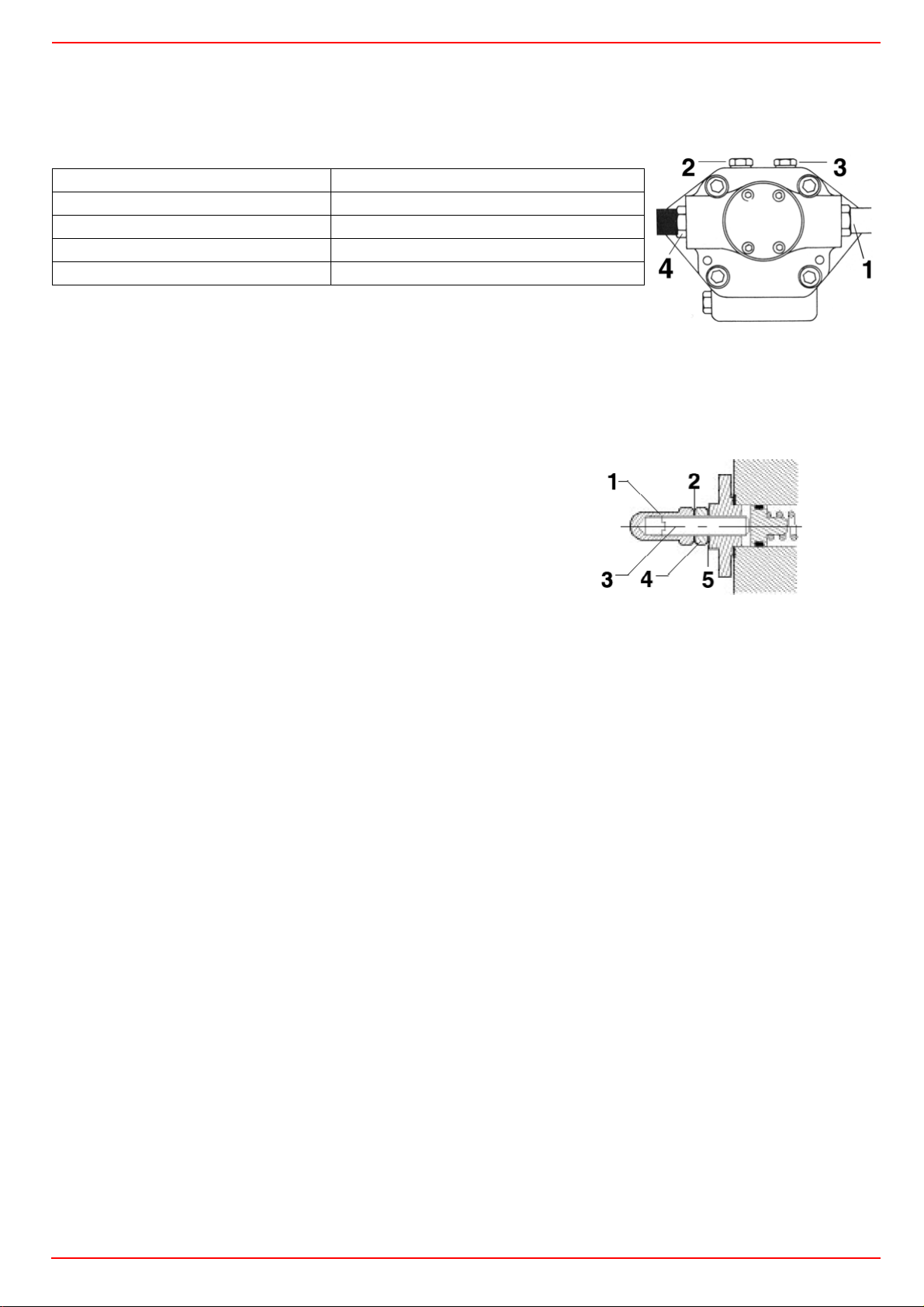
Suntec T pump
Viscosity 4 - 800 cSt
Oil temperature 0 - 140 °C
Minimum suction pressure - 0.45 bar to prevent gasing
Maximum suction pressure 5 bar
Rated speed 3600 rpm max.
Key
1 To pressure adjusting valve G3/4
2 Pressure/vacuum gauge port to measure the inlet pressure/vacuum G1/4
3 Pressure gauge port G1/4
4 Inlet G3/4
Suntec TV Pressure governor
Pressure adjustment
Remove cap-nut 1 and the gasket 2, unscrew the lock nut 4. To increase pressure,
twist adjusting screw 3 clockwise.
To decrease the pressure, twist screw counterclockwise. Tight the lock nut 4, refit the
gasket 2 and the cap nut 1.
Key
1Cap nut
2 Gasket
3 Adjusting screw
4 Lock nut
5 Gasket
Fig. 15
Assembling the light oil flexible hoses
To connect the flexible light oil hoses to the pump, proceed as follows, according to the pump provided:
1 remove the closing nuts A and R on the inlet and return connections of the pump;
2 screw the rotating nut of the two flexible hoses on the pump being careful to avoid exchanging the inlet and return lines: see
the arrows marked on the pump that show the inlet and the return (see prevoius paragraph).
20
Page 21
CIB UNIGAS - M039180CC
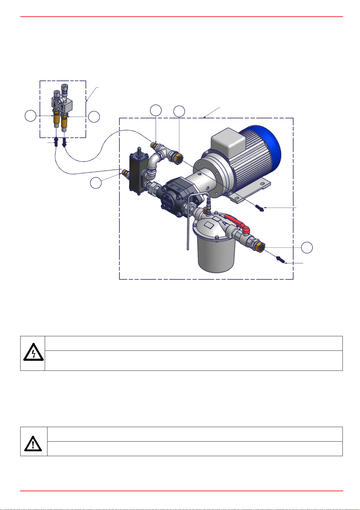
Connecting the burner to the light oil pumping unit
Follow the scheme in the picture below to connect the burner to the oil pumping unit. The pump sends the oil coming from the tank to
the burner. The pressure governor makes the oil reach the nozzle at the required pressure, while the excess of oil goes back to the
tank. To change the delivery pressure act on the VRM adjusting screw of the delivery pressure governor.
A BORDO BRUCIATORE
ON BURNER
D
IN
OUT
E
VRM
D
E
E
GRUPPO POMPA SEPARATO
SEPARATE PUMPING UNIT
AL SERBATOIO
TO TANK
A
DAL SERBATOIO
FROM TANK
CAUTION: caps are not sealing type but used for shipment only. The flexible hoses between the pump and the burner are the ones called (ion the label) “Oil high pressure flexible hose”. The flexible hose called “Oil low pressure flexible hose” is the one to be connected
upstraem the oil filter.
Electrical connections
Respect the basic safety rules. make sure of the connection to the earthing system. do not reverse the phase and
neutral connections. fit a differential thermal magnet switch adequate for connection to the mains.
ATTENTION: before executing the electrical connections, pay attention to turn the plant’s switch to OFF and be
sure that the burner’s main switch is in 0 position (OFF) too. Read carefully the chapter “WARNINGS”, and the
“Electrical connections” section.
To execute the electrical connections, please refer to the attached electrical wiring diagrams.
To execute the electrical connections, proceed as follows:
1 remove the cover from the electrical board, unscrewing the fixing screws;
2 execute the electrical connections to the supply terminal board as shown in the following diagrams,
3 check the direction of the fan motor (see next pargraph)
4 refit the panel cover.
WARNING: The burner is provided with an electrical bridge between terminals 6 and 7; when connecting the high/
low flame thermostat, remove this bridge before connecting the thermostat.
IMPORTANT: Connecting electrical supply wires to the burner teminal block MA, be sure that the ground wire is
longer than phase and neutral ones.
Rotation of fan motor and pump motor
Once the electrical connection of the burner is executed, remember to check the rotation of the motor. The motor should rotate according to the indication on the body. In the event of wrong rotation, reverse the three-phase supply and check again the rotation of the
motor.
21
Page 22
CIB UNIGAS - M039180CC
ADJUSTMENTS
ATTENTION: before starting the burner up, be sure that the manual cutoff valves are open and check that the pressure upstream the gas train complies the value quoted on paragraph “Technical specifications”. Be sure that the
mains switch is closed.
ATTENTION: During commissioning operations, do not let the burner operate with insufficient air flow (danger of formation of
carbon monoxide); if this should happen, make the gas decrease slowly until the normal combustion values are achieved.
WARNING: EVER LOOSE THE SEALED SCREWS, OTHERWISE THE DEVICE WARRANTY WILL BE IMMEDIATELY
INVALIDATE!
Combustion head gas pressure curves depending on the flow rate
Curves are referred to pressure = 0mbar in the combustion head!
The curves referred to the gas pressure in the combustion head, depending on the gas flow rate, are referred to the burner properly
adjusted (percentage of residual O
limits). During this stage, the combustion head, the gas butterfly valve and the servocontrol are at the maximum opening. Refer to Fig.
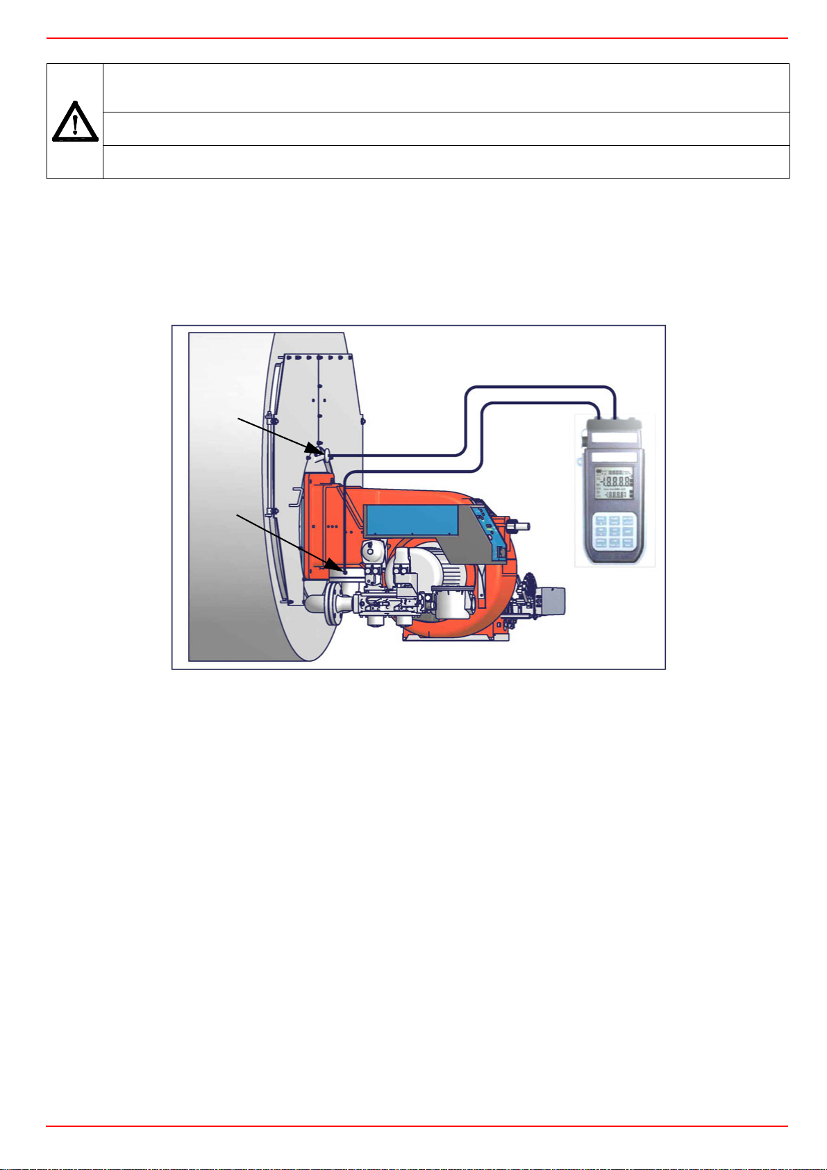
16, showing the correct way to measure the gas pressure, considering the values of pressure in combustion chamber, surveyed by
means of the pressure gauge or taken from the boiler’s Technical specifications.
in the flues as shown in the “Recommended combustion values” table and CO in the standard
2
1
2
4
3
Fig. 16
Key
1 Generator
2 Pressure outlet on the combustion chamber
3 Gas pressure outlet on the butterfly valve
4 Differential pressure gauge
Measuring the gas pressure in the combustion head
In order to measure the pressure in the combustion head, insert the pressure gauge probes: one into the combustion chamber’s pressure outlet (Fig. 16-2) to get the pressure in the combustion chamber and the other one into the butterfly valve’s pressure outlet of the
burner (Fig. 16-3). On the basis of the measured differential pressure, it is possible to get the maximum flow rate: in the pressure - rate
curves (showed on the next paragraph), it is easy to find out the burner’s output in Stm
measured in the combustion head (quoted on the y axis). The data obtained must be considered when adjusting the gas flow rate.
NOTE: THE PRESSURE-RATE CURVES ARE GIVEN AS INFORMATION ONLY; FOR A PROPER SETTING OF THE GAS RATE,
PLEASE REFER TO THE GAS METER READING.
3
/h (quoted on the x axis) from the pressure
22
Page 23

Pressure - rate in combustion head curves
HTP1030
140
120
100
80
60
CIB UNIGAS - M039180CC
Gas pressure in
combustion head
HTP1050
100
90
80
70
60
50
40
30
Gas pressure in
combustion head
20
10
HTP1080
40
20
0
200 300 400 500 600 700 800 900 1000 1100 1200 1300 1400
Gas rate Stm
0
300 400 500 600 700 800 900 1000 1100 1200 1300 1400 1500 1600 1700
Gas rate Stm
3
/h
3
/h
16 0
14 0
12 0
10 0
80
60
Gas pressure in
combustion head
40
20
0
400 500 600 700 800 900 1000 1100 1200 1300 1400 1500 1600 1700 1800 1900 2000 2100 2200
Gas rate Stm3/h
IMPORTANT! the combustion air excess must be adjusted according to the in the following chart:
Recommended combustion parameters
Fuel
Recommended (%) CO
Recommended (%) O2
2
Natural gas 9 ÷ 10 3 ÷ 4.8
Light oil 11.5 ÷ 13 2.9 ÷ 4.9
23
Page 24
CIB UNIGAS - M039180CC
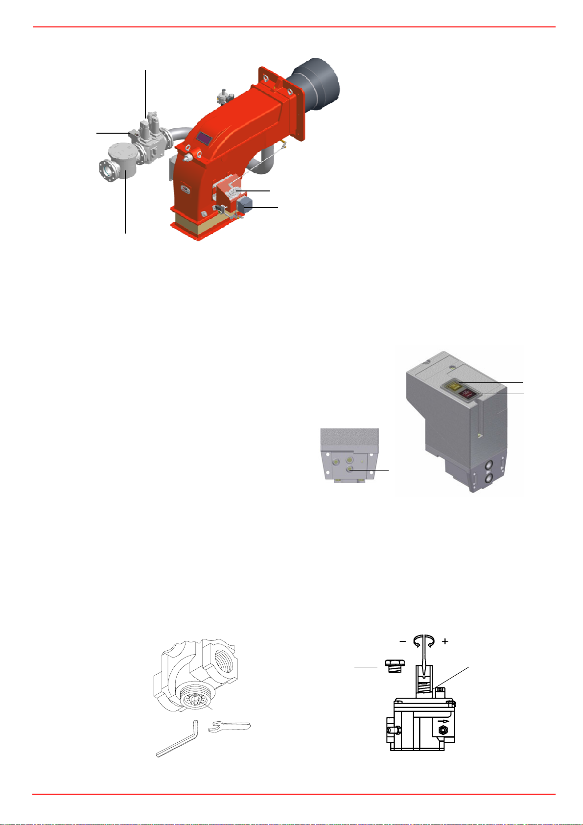
3
Keys
1 Gas filter
2 Gas proving system
2
3Gas valves
4 Adjusting cam
5Actuator
4
5
1
Fig. 17
Gas Filter
The gas filters remove the dust particles that are present in the gas, and prevent the elements at risk (e.g.: burner valves, counters and
regulators) from becoming rapidly blocked. The filter is normally installed upstream from all the control and on-off devices.
VPS504 Gas proving system
The VPS504 check the operation of the seal of the gas shut off valves. This check is carried out as soon as the boiler thermostat gives
a start signal to the burner, creating, by means of the diaphragm
pump inside it, a pressure in the test space of 20 mbar higher than
the supply pressure.
When wishing to monitor the test, install a pressure gauge ranged to
that of the pressure supply point PA.
If the test cycle is satisfactory, after a few seconds the consent light
LC (yellow) comes on. In the opposite case the lockout light LB (red)
comes on.
To restart it is necessary to reset the appliance by pressing the illuminated pushbutton LB.
PA
Fig. 18
LC
LB
Adjusting the injector gas flow rate: Brahma EG12*R valve and pressure governor
To change the injector gas valve flow rate, proceed as follows:
1 remove the protection on the bottom of the valve, moving it counterclockwise (see next picture);
2 rotate clockwise the nut 1 as shown, to close the valve; counterclockwise to open the valve.
To perform a finest adjustment, act directly on the pressure governor as follows (see next picture):
3 remove the cap T: to increase theoutlet gas pressure, use a screwdriver on the screw TR as shown in the picture below. Screw to
increase the pressure, unscrew to decrease; once the regulation is performed, replace cap T.
Brahma gas valve EG*12R
T
1
TR
Pressure stabiliser
24
Page 25
CIB UNIGAS - M039180CC
Adjustments - brief description
Adjust the air and gas flow rates at the maximum output (“high flame”) first, by means of the air damper and the adjusting cam respectively.
z Check that the combustion parameters are in the suggested limits.
z Check the flow rate measuring it on the counter or, if it was not possible, verifying the combustion head pressure by means of a dif-
ferential pressure gauge, as described on par. “Measuring the gas pressure in the combustion head” on page 22.
z Then, adjust the combustion values corresponding to the points between maximum and minimum: set the shape of the adjusting
cam foil. The adjusting cam sets the air/gas ratio in those points, regulating the opening-closing of the throttle gas valve.
z Set, now, the low flame output, acting on the low flame microswitch of the actuator in order to avoid the low flame output increasing
too much or that the flues temperature gets too low to cause condensation in the chimney.
Now, adjust the burner according to the actuator model provided.
Adjustment procedure
To change the burner setting during the testing in the plant, follow the next procedure.
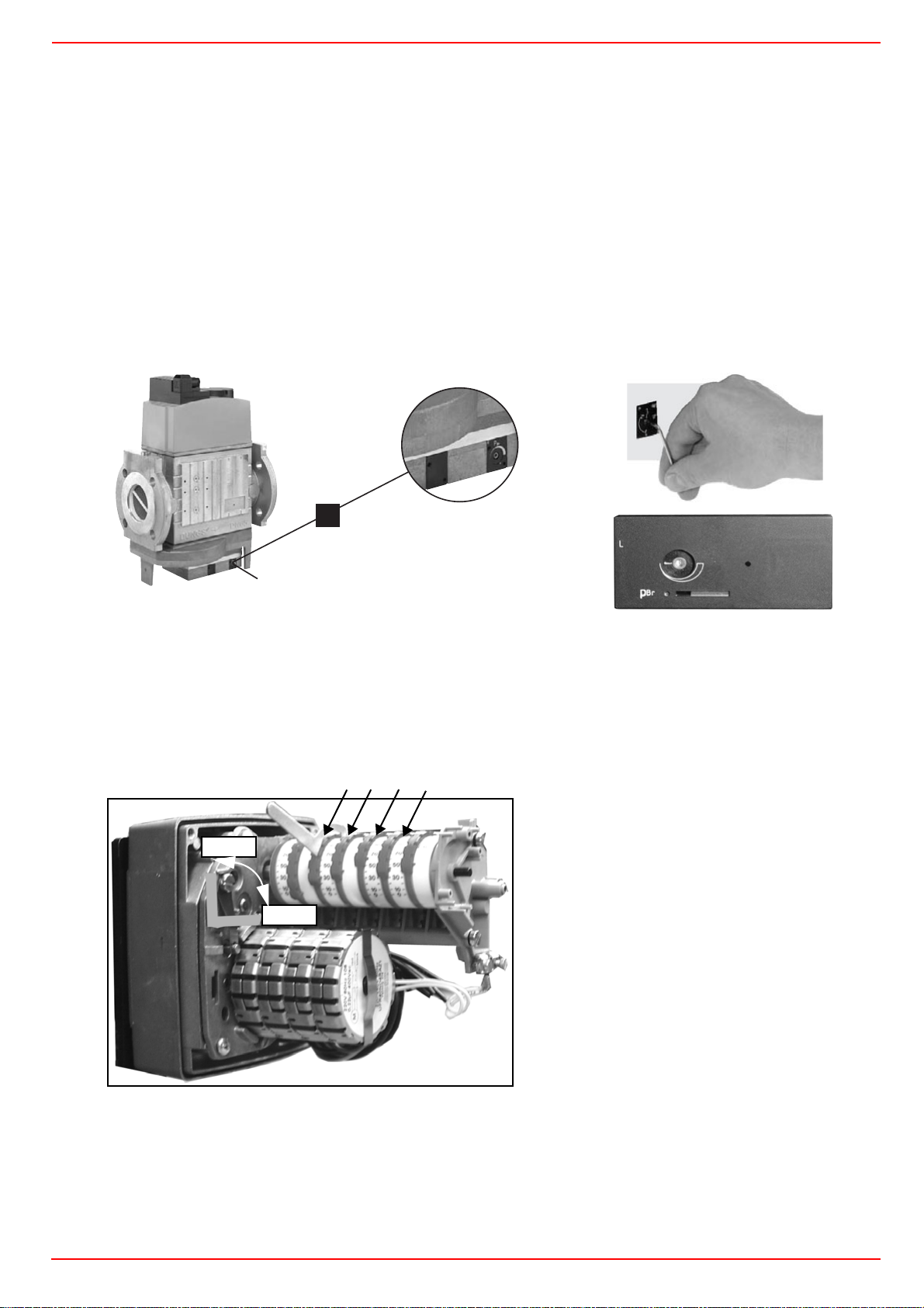
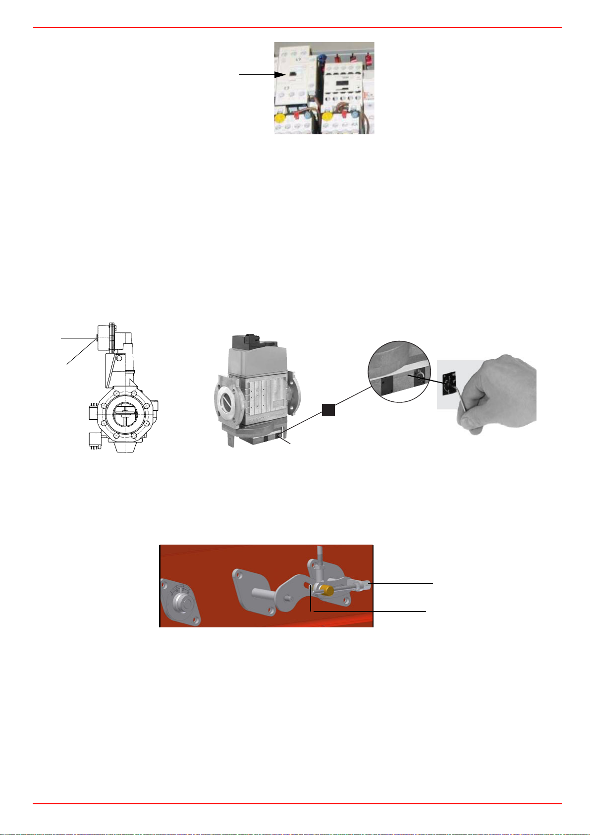
On the DUNGS MBC..SE gas valves group, set the pressure regulator to 1/3 of its stroke, using a 2.5 allen key.
1
#S
*OOFOTFDITLBOUTDIMàTTFM/P
"MMFOLFZOP
$MÏEFTJYQBOTNÉMFOP
$IJBWFFTBHPOBMFDBWBOS
Pressure setting
1 Before starting the burner up, drive the high flame actuator microswitch matching the low flame one (in order to let the burner ope-
rates at the lowest output) to safely achieve the high flame stage.
2 cam IV (stroke limitation cam) must be set a little higher than the cam III to limit the output in the first seconds the flame appears;
NOTE: cam IV must shift according to cam III.
IIIIII
IV
MAN
Actuator cams
I High flame
AUTO
II Stand-by and Ignition
III Low flame (gas)
IV Low flame (oil)
V Stroke limitation
1 turn the burner on by selecting GAS fuel by means of the burner CM switch (it is placed on the burner control panel)
2 open the electrical panel to check the fan motor rotation and act directly on the related contactor (see next picture).
25
Page 26
CIB UNIGAS - M039180CC
CV
3 Before starting the burner up, drive the high flame actuator microswitch matching the low flame one (in order to let the burner ope-
rates at the lowest output) to safely achieve the high flame stage.
4 Start the burner up by means of the thermostat series and wait until the pre-purge time comes to an end and that the burner starts
up;
5 drive the burner to high flame stage, by means fo the thermostat TAB.
6 Then move progressively the microswitch to higher values until it reaches the high flame position; always check the combustion
values and eventually adjusting the gas by means of the valves group stabiliser.
7 go on adjusting air and gas flow rates: check, continuosly, the flue gas analisys, as to avoid combustion with little air; dose the air
according to the gas flow rate change following the steps quoted below;
8 acting on the pressure stabiliser of the valves group, adjust the gas flow rate in the high flame stage as to meet the values
requested by the boiler/utilisation:
- Siemens VGD valves group: remove cap T and act on the VR adjusting screw to increase or decrease the pressure and conse-
quently the gas rate; screwind VR the rate increases, unscrewing it decreases (see next figure).
- Dungs MBC..SE valves group: act on its pressure governor to increase or decrease the pressure and consequently the gas
rate.
T
VR
1
#S
*OOFOTFDITLBOUTDIMàTTFM/P
"MMFOLFZOP
$MÏEFTJYQBOTNÉMFOP
:
Siemens VGD..
$IJBWFFTBHPOBMFDBWBOS
Dungs MBC..SE
9 To adjust the air flow rate in the high flame stage, loose the RA nut and screw VRA as to get the desired air flow rate: moving
the rod TR towards the air damper shaft, the air damper opens and consequently the air flow rate increases, moving it far from the
shaft the air damper closes and the air flow rate decreases.
Note: once the procedure is perfomed, be sure that the blocking nut RA is fasten. Do not change the position of the air damper
rods.
VRA
RA
Note: once the procedure is perfomed, be sure that the blocking nut RA is fasten. Do not change the position of the air damper
rods.
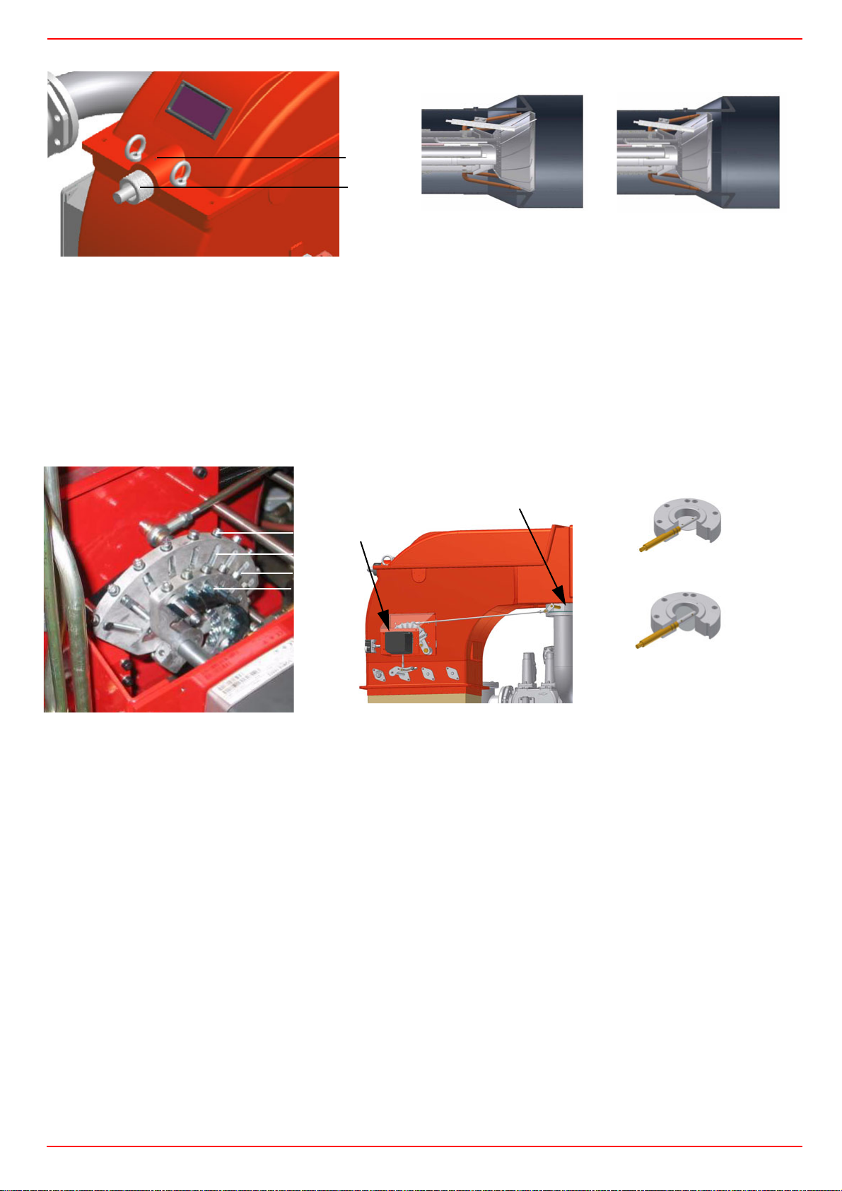
10 Only if necessary, change the combusiton head position: to let the burner operate at a lower output, loose the VB screw and move
progressively back the combustion head towards the MIN position, by turning clockwise the VRT ring nut. Fasten VB screw when
the adjustment is accomplished.
26
Page 27
CIB UNIGAS - M039180CC
VB
VRT
“MAX”head position
head position
Attention! if it is necessary to change the head position, repeat the air and gas adjustments described above.
11 the air and gas rate are now adjusted at the maximum power stage, go on with the point to point adjustement on the SV1 (gas
side) adjusting cam as to reach the minimum output point.
12 as for the point-to-point regulation, move the gas low flame microswitch (cam III) a little lower than the maximum position (90°);
13 set the TAB thermostat to the minimum in order that the actuator moves progressively towards the low flame position;
14 move cam III to the minimum to move the actuator towards the low flame until the two bearings find the adjusting screw that refers
to the lower position: screw V1 to increase the rate, unscrew to decrease.
15 Move again cam III towards the minimum to meet the next screw on the adjusting cam and repeat the previous step; go on this way
as to reach the desired low flame point.
16 Now adjust the pressure switches (see next paragraph).
VF
V1
SC
SV1
V2
Closed butterfly valveт
SV2
Opened butterfly valve
SC
Calibration of air pressure switch
To calibrate the air pressure switch, proceed as follows:
z Remove the transparent plastic cap.
z Once air and fuel setting have been accomplished, startup the burner.
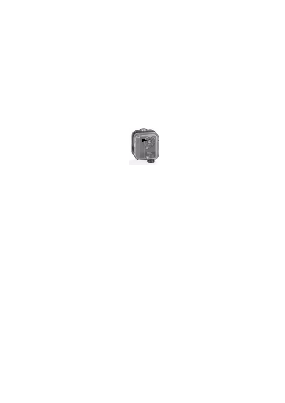
z During the pre-purge phase o the operation, turn slowly the adjusting ring nut VR in the clockwise direction (to increase the adju-
sting pressure) until the burner lockout, then read the value on the pressure switch scale and set it to a value reduced by 15%.
z Repeat the ignition cycle of the burner and check it runs properly.
z Refit the transparent plastic cover on the pressure switch.
Calibration of low gas pressure switch
As for the gas pressure switch calibration, proceed as follows:
z Be sure that the filter is clean.
z Remove the transparent plastic cap.
z While the burner is operating at the maximum output, test the gas pressure on the pressure port of the minimum gas pressure
switch.
z Slowly close the manual cutoff valve (placed upstream the pressure switch, see gas train installation diagram), until the detected
pressure is reduced by 50%. Pay attention that the CO value in the flue gas does not increase: if the CO values are higher than the
limits laid down by law, slowly open the cutoff valve as to get values lower than these limits.
z Check that the burner is operating correctly.
z Clockwise turn the pressure switch adjusting ring nut (as to increase the pressure value) until the burner stops.
z Slowly fully open the manual cutoff valve.
z Refit the transparent plastic cover on the pressure switch.
27
Page 28
CIB UNIGAS - M039180CC
Adjusting the high gas pressure switch (when provided)
To calibrate the high pressure switch, proceed as follows according to its mounting position:
1 remove the pressure switch plastic cover;
2 if the maximum pressure switch is mounted upstreaam the gas valves: measure the gas pressure in the network, when flame is off;
by means of the adjusting ring nut VR, set the value read, increased by the 30%.
3 if the maximum pressure switch is mounted downstream the “gas governor-gas valves” group and upstream the butterfly valve:
light the burner, adjust it according to the procedure in the previous paragrph. Then, measure the gas pressure at the operating
flow rate, downstream the “gas governor-gas valves” group and upstream the butterfly valve; by means of the adjusting ring nut
VR, set the value read on step 2, increased by the 30%;
4 replace the plastic cover.
PGCP Gas leakage pressure switch (witn SiemensLDU/Siemens LMV burner control)
z remove the pressure switch plastic cover;
z adjust the PGCP pressure switch to the same value set for the minimum gas pressure switch;
z replace the plastic cover.;
VR
Fig. 19
Fully modulating burners
To adjust the fully-modulating burners, use the CMF switch on the burner control panel (see next picture), instead of the TAB thermostat as described on the previous paragraphs about the progressive burners. Go on adjusting the burner as described before, paying
attention to use the CMF switch intead of TAB.
The CMF position sets the oprating stages: to drive the burner to the high-flame stage, set CMF=1; to drive it to the low-flame stage, set
CMF=2.
To move the adjusting cam set CMF=1 or 2 and then CMF=0.
CMF = 0 stop at the current position
CMF = 1 high flame operation
CMF = 2 low flame operation
CMF = 3 automatic operation
28
Page 29
CIB UNIGAS - M039180CC
Adjustment for light oil operation
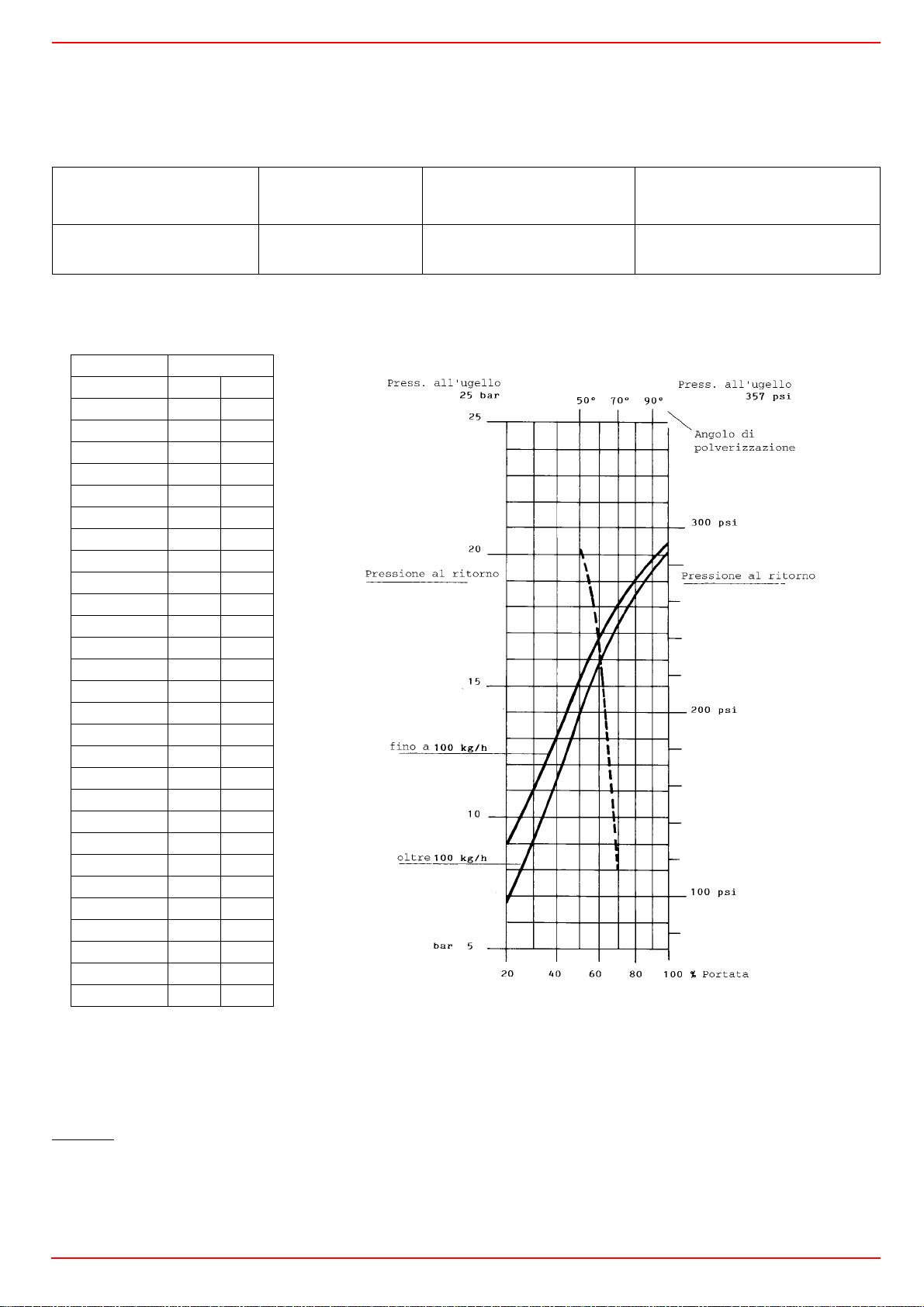
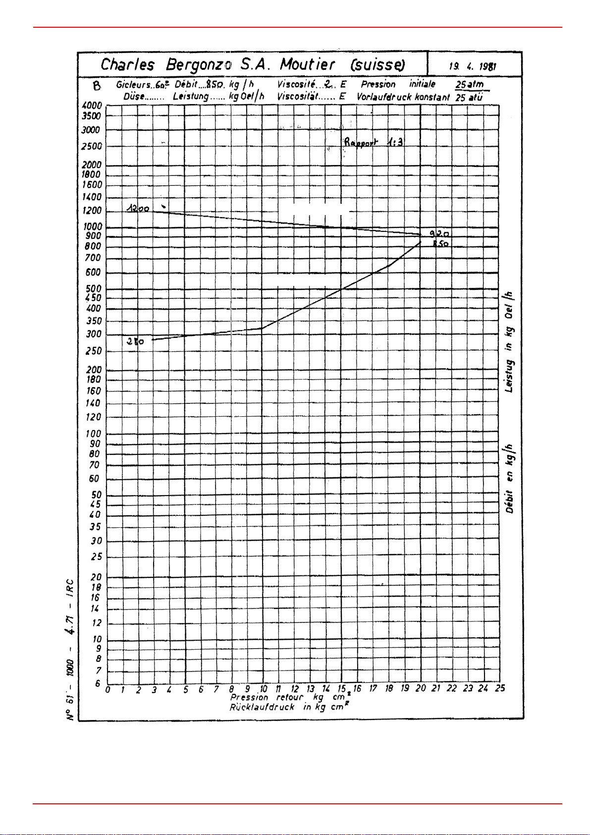
The light oil flow rate can be adjusted choosing a by-pass nozzle that suits the boiler/utilisation output and setting the delivery and
return pressure values according to the ones quoted on the chart below and the diagram on Fig. 20 (as far as reading the pressure
values, see next paragraphs).
NOZZLE
FLUIDICS WR2 /
BERGONZO B / BERGONZO C
FLOW RATE kg/h
DIMENSIONS Min Max
40 13 40
50 16 50
60 20 60
70 23 70
80 26 80
90 30 90
100 33 100
115 38 115
130 43 130
145 48 145
160 53 160
180 59 180
200 66 200
225 74 225
250 82 250
275 91 275
300 99 300
330 109 330
360 119 360
400 132 400
450 148 450
500 165 500
550 181 550
600 198 600
650 214 650
700 231 700
750 250 750
800 267 800
DELIVERY
PRESSURE
bar
25
Pressure on return
PRESSURE MAX.
Pressure at nozzle 25bar
Up to 100kg/h
Over 100kg/h
RETURN
bar
20
RETURN
PRESSURE MIN.
bar
7 (recommended)
Fig. 20
Pressure at nozzle 357psi
Atomisation angle
Pressure on return
% Flow rate
Example:
20Fig. 20).
-----------Atomisation angle according to the return pressure
______ % Flow rate
Tab. 1
as for over 100kg/h nozzles, the 80% of the nozzle flow rate can be obtained with a return pressure at about 18bar (see Fig.
29
Page 30
CIB UNIGAS - M039180CC
Pump flow rate
Nozzle flow rate
Fig. 21 - Bergonzo nozzle - example with 850kg/h nozzle
1 Once the air and gas flow rates are adjusted, turn the burner off, turn the burner on again by means of the CM selector to switch to
the light oil operation (OIL, on the burner control panel).
2 with the electrical panel open, prime the oil pump acting directly on the related CP contactor (see next picture): check the pump
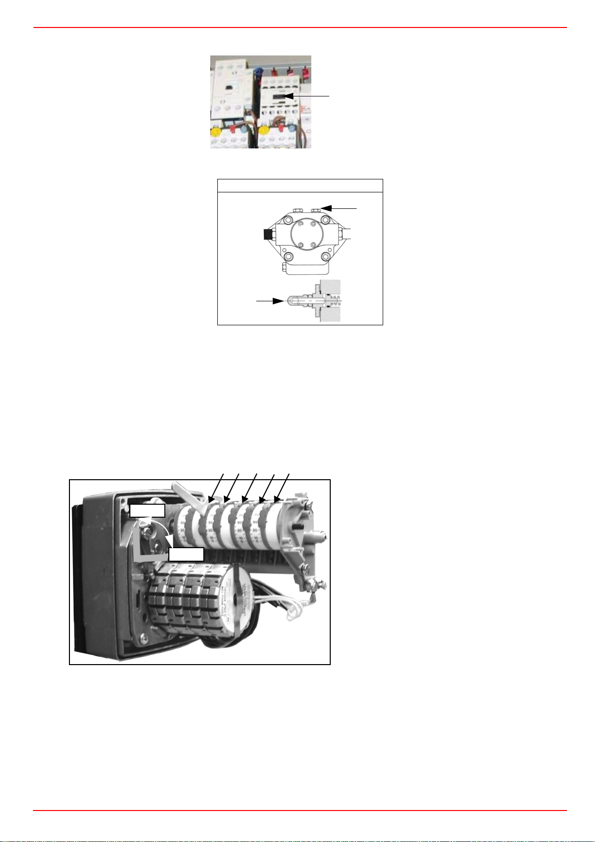
30
Page 31
CIB UNIGAS - M039180CC
M
motor rotation and keep pressing for some seconds until the oil circuit is charged;
CP
3 bleed the air from the M pressure gauge port (Fig. 22) by loosing the cap without removing it, then release the contactor.
Suntec T..
VR
Fig. 22
4 Before starting the burner up, drive the high flame actuator microswitch matching the low flame one (in order to let the burner ope-
rates at the lowest output) to achieve safely the high flame stage .
5 record the high flame value set during the gas operation adjustments (see previous paragraphs);
6 start the burner up by means of the thermostat series and wait until the pre-purge time comes to an end and that the bruner starts
up;
7 drive the burner to high flame stage, by means fo the thermostat TAB.
8 Then move progressively the microswitch to higher values until it reaches the high flame position; always check the combustion
values and eventually adjusting the oil pressure (see next step).
V
IIIIII
IV
MAN
Actuator cams
I High flame
AUTO
II Stand-by and Ignition
III Low flame (gas)
IV Low flame (oil)
V Stroke limitation
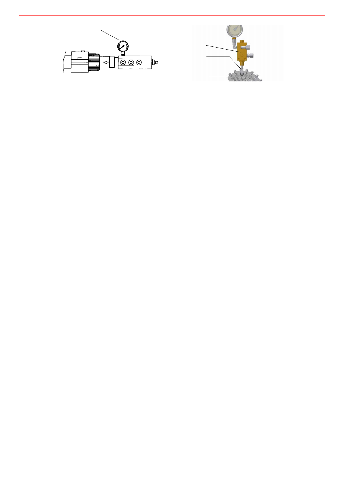
9 the nozzle supply pressure is already factory-set and must not be changed. Only if necessary, adjust the supply pressure as fol-
lows (see related paragraph);insert a pressure gauge into the port shown on Fig. 23 and act on on the pump adjusting screw VR
(see Fig. 22 and page 20) as to get the nozzle pressure at 25bar (according to the nozzle model provided- see page 29).
31
Page 32
CIB UNIGAS - M039180CC
P
ressure gauge port
PG
RP
V2
SV2
Fig. 23 Fig. 24
10 in order to get the maximum oil flow rate, adjust the pressure (reading its value on the PG pressure gauge) without changing the air flow
rate set during the gas operation adjustments (see previous paragraph): checking always the combustion parameters, the adjustment is to
SV2
be performed by means of the
adjusting cam screw (see picture) when the cam has reached the high flame position.
11 as for the point-to-point regulation in order to set the cam foil shape, move the oil low flame microswitch (cam IV) a little lower than
the maximum position (90°);
12 set the TAB thermostat to the minimum in order that the actuator moves progressively towards the low flame position;
13 move cam IV (oil low flame) towards the minimum to move the actuator towards the low flame until the two bearings find the adju-
sting screw that refers to a lower position: screw V2 to increase the rate, unscrew to decrease, in order to get the pressure as
showed on chart/diagram on “Adjustment for light oil operation” on page 29, according to the requested rate.
14
Move again cam V towards the minimum to meet the next screw on the adjusting cam and repeat the previous step; go on this way
as to reach the desired low flame point.
15 The low flame position must never match the ignition position that is why cam IV must be set 20°- 30° more than the ignition posi-
tion.
16 Set cam V (“stroke limitation cam”) 5° higher than the lowest “low flame cam” (cam III or cam IV).
17 Turn the burner off; then start it up again. If the adjustment is not correct, repeat the previous steps.
18 Replace the actuator and control panel covers.
32
Page 33
CIB UNIGAS - M039180CC
As far as fully-modulating burners, see paragraph “Fully modulating burners” on page 28.
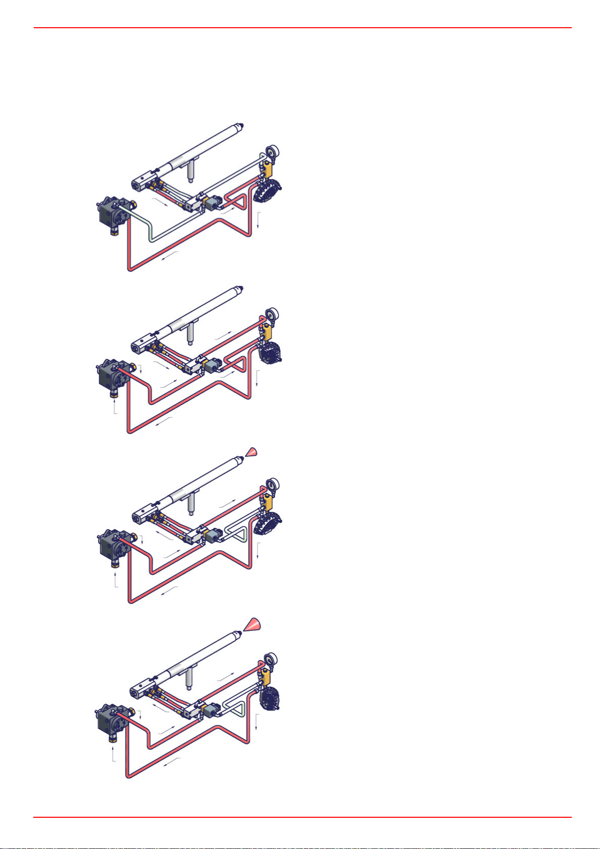
Light oil circuitOil circuit
The fuel is pushed into the pump 1 to the nozzle 3 at the delivery pressure set by the pressure governor. The solenoid valve 2 stops the
fuel immission into the combustion chamber. The fuel flow rate that is not burnt goes back to the tank through the return circuit. The
spill-back nozzle is feeded at constant pressure, while the return line pressure is adjusted by means of the pressure governor controlled
by an actuator coupled to an adjusting cam. The fuel amount to be burnt is adjusted by means of the burner actuator according to the
adjustments set (see prevoius paragraph).
3
5
6
2
1
4
3
5
Fig. 25 - Stand-by
6
Fig. 26 - Prepurge
2
1
4
3
5
6
2
1
4
Fig. 27 - Low flame
3
5
6
Key
1 Light oil pump
Fig. 28 - High flame
2 Light oil solenoid valve
2
1
4
3 Nozzle
4 Adjusting cam
5 Pressure gauge
6 Pressure governor
33
Page 34

CIB UNIGAS - M039180CC
PART II: OPERATION
LIMITATIONS OF USE
THE BURNER IS AN APPLIANCE DESIGNED AND CONSTRUCTED TO OPERATE ONLY AFTER BEING CORRECTLY CONNECTED TO A HEAT GENERATOR (E.G. BOILER, HOT AIR GENERATOR, FURNACE, ETC.), ANY OTHER USE IS TO BE CONSIDERED IMPROPER AND THEREFORE DANGEROUS.
THE USER MUST GUARANTEE THE CORRECT FITTING OF THE APPLIANCE, ENTRUSTING THE INSTALLATION OF IT TO
QUALIFIED PERSONNEL AND HAVING THE FIRST COMMISSIONING OF IT CARRIED OUT BY A SERVICE CENTRE AUTHORISED BY THE COMPANY MANUFACTURING THE BURNER.
A FUNDAMENTAL FACTOR IN THIS RESPECT IS THE ELECTRICAL CONNECTION TO THE GENERATOR’S CONTROL AND
SAFETY UNITS (CONTROL THERMOSTAT, SAFETY, ETC.) WHICH GUARANTEES CORRECT AND SAFE FUNCTIONING OF
THE BURNER.
THEREFORE, ANY OPERATION OF THE APPLIANCE MUST BE PREVENTED WHICH DEPARTS FROM THE INSTALLATION
OPERATIONS OR WHICH HAPPENS AFTER TOTAL OR PARTIAL TAMPERING WITH THESE (E.G. DISCONNECTION, EVEN
PARTIAL, OF THE ELECTRICAL LEADS, OPENING THE GENERATOR DOOR, DISMANTLING OF PART OF THE BURNER).
NEVER OPEN OR DISMANTLE ANY COMPONENT OF THE MACHINE.
OPERATE ONLY THE MAIN SWITCH, WHICH THROUGH ITS EASY ACCESSIBILITY AND RAPIDITY OF OPERATION ALSO
FUNCTIONS AS AN EMERGENCY SWITCH, AND ON THE RESET BUTTON.
IN THE EVENT OF REPEATED LOCKOUTS, DO NOT PERSIST WITH THE RESET BUTTON AND CONTACT QUALIFIED PERSONNEL WHO WILL PROCEED TO ELIMINATE THE MALFUNCTION.
WARNING: DURING NORMAL OPERATION THE PARTS OF THE BURNER NEAREST TO THE GENERATOR (COUPLING
FLANGE) CAN BECOME VERY HOT, AVOID TOUCHING THEM SO AS NOT TO GET BURNT.
34
Page 35
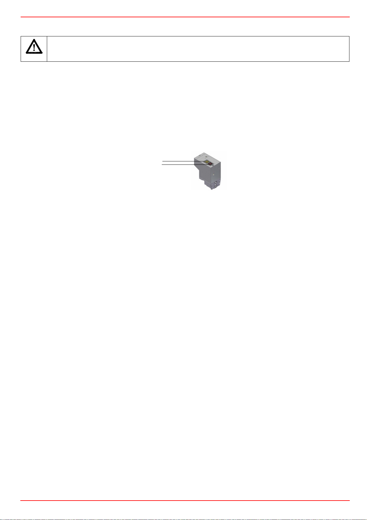
CIB UNIGAS - M039180CC
OPERATION
ATTENTION: before starting the burner up, be sure that the manual cutoff valves are open and check that the pressure upstream the gas train complies the value quoted on paragraph “Technical specifications”.
z Choose the typer of fuel by turning the burner switch, on the burner control panel.
CAUTION: if the fuel chosen is light oil, be sure the cutoff valves on the feed and return pipes are open.
z Check the control box is not locked (signalling light on); if so, reset it by means of the reset pushbutton.
z Check the series of thermostats and pressure switches turn the burner to on.
Gas operation
z Check the gas feeding pressure is sufficient (signalling lamp on).
Burners provided with gas proving system: the gas proving system test begins; when the test is performed the proving system LED
turns on. At the end of the test, the burner staring cycle begins: in case of leakage in a valve, the gas proving system stops the burner
and the related lamp turns on. Reset it, by means of the reset pushbutton on the device, in burners with VPS504 (pushbutton LB in picture), or by the pushbutton on the burner panel if this one is fitted with LDU11 proving system.
LC
LB
VPS504
NOTE: if the burner is fitted with Dungs VPS504, the pre-purgue phase starts once the gas proving system is successfully performed.
Since the pre-purgue phase must be carried out with the maximum air rate, the control box drives the actuator opening and when the
maximum opening position is achieved, the pre-purge time counting starts.
z At the end of the pre-purge time, the actuator drives the complete closing (ignition with gas position) and, as this is achieved the
ignition transformer is energised; the ignitor gas valves and the main gas valves open.
z Few seconds after the valves opening, the transformer is de-energised and lamp L turns off.
z The burner is now operating, meanwhile the actuator goes to the high flame position and, after some seconds, the two-stage ope-
ration begins; the burner is driven automatically to high flame or low flame, according to the plant requirements.
Operation in high or low flame is signalled by the related lamp on the burner control panel.
Light oil operation
z The fan motor starts and the pre-purge phase as well. Since the pre-purge phase must be carried out at the maximum air rate, the
control box drives the actuator opening and when the maximum opening position is reached, the pre-purge time counting starts.
z At the end of the pre-purge time, the actuator is in the light oil ignition position: the ignition transformer is energised (lamp on); the
ignitor gas valves and the light oil valves open. Few seconds after the valves opening, the transformer is de-energised and lamp
turns off.
z The burner is now operating, meanwhile the actuator goes to the high flame position; after some seconds, the two-stage operation
begins; the burner is driven automatically to high flame or low flame, according to the plant requirements.
Operation in high or low flame is signalled by the related lamps on the burner control panel.
35
Page 36
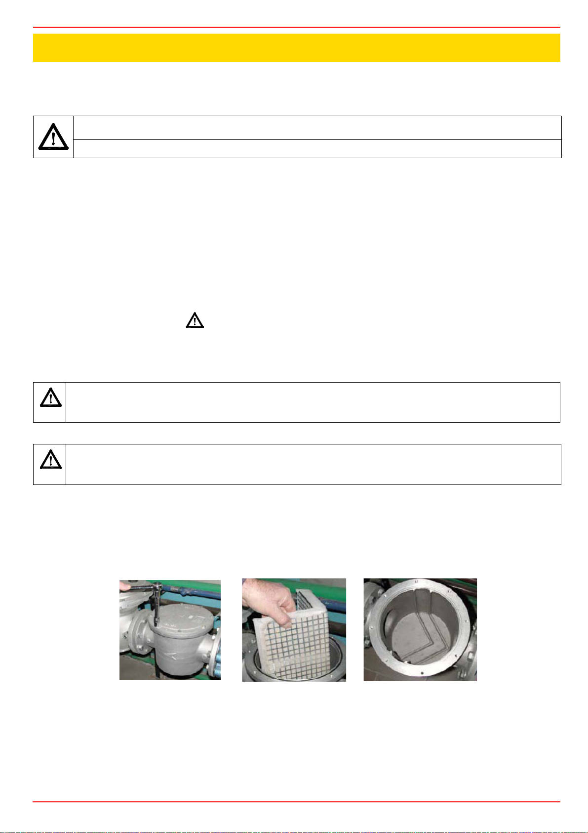
CIB UNIGAS - M039180CC
PART III: MAINTENANCE
At least once a year carry out the maintenance operations listed below. In the case of seasonal servicing, it is recommended to carry
out the maintenance at the end of each heating season; in the case of continuous operation the maintenance is carried out every 6
months.
WARNING: ALL OPERATIONS ON THE BURNER MUST BE CARRIED OUT WITH THE MAINS DISCONNECTED AND
THE FUEL MANAUL CUTOFF VALVES CLOSED!
ATTENTION: READ CAREFULLY THE “WARNINGS” CHAPTER AT THE BEGINNIG OF THIS MANUAL.
ROUTINE MAINTENANCE
z Check and clean the gas filter cartridge, if necessary replace it (see next paragraghs);
z Check and clean the fuel filter cartdrige, replace if necessary.
z Check and clean the filter inside the light oil pump: filter must be thoroughly cleaned at least once in a season to ensure correct
working of the fuel unit. To remove the filter, unscrew the four screws on the cover. When reassemble, make sure that the filter is
mounted with the feet toward the pump body. If the gasket between cover and pump housing should be damaged, it must be repla-
ced. An external filter should always be installed in the suction line upstream of the fuel unit.
z Check the fuel hoses for possible leaks.
z Remove, check and clean the combustion head (see page 37);
z Check ignition electrodes, clean, adjust and, if necessary, replace them (see page 39);
z Check and carefully clean the UV detector, replace it if necessary; if in doubt, check the detection current, once the burner starts up
(see on page 40).
z Remove and clean the fuel nozzle (Important: cleaning must be performed using solvent, not metal tools!). At the end of
maintenance operations after the burner reassembly, light the flame and check its shape, replacing the nozzle whenever a questio-
nable flame shape appears. Whenever the burner is used intensely, we recommend preventively replacing the nozzle at the start of
each heating season.
z Clean and grease sliding and rotating parts.
ATTENTION: when servicing, if it was necessary to disassemble the gas train parts, remember to execute the gas proving
test, once the gas train is reassembled, according to the procedure imposed by the law in force.
Gas filter maintenance
ATTENTION: Before opening the filter, close the manual cutoff valve downstream the filter and bleed the gas; check that
inside the filter there is no pressurised gas.
To clean or remove the filter, proceed as follows:
1 remove the cap unscrewing the fixing screws (A);
2 remove the filtering cartridge (B), clean it using water and soap, blow it with compressed air(or replace it, if necessary)
3 replace the cartridge in its proper position taking care to place it inbetween the guides as not to hamper the cap replacement;
4 be sure to replace the Or ring into its place (C) and replace the cover fastening by the proper screws (A).
A
B
C
36
Page 37
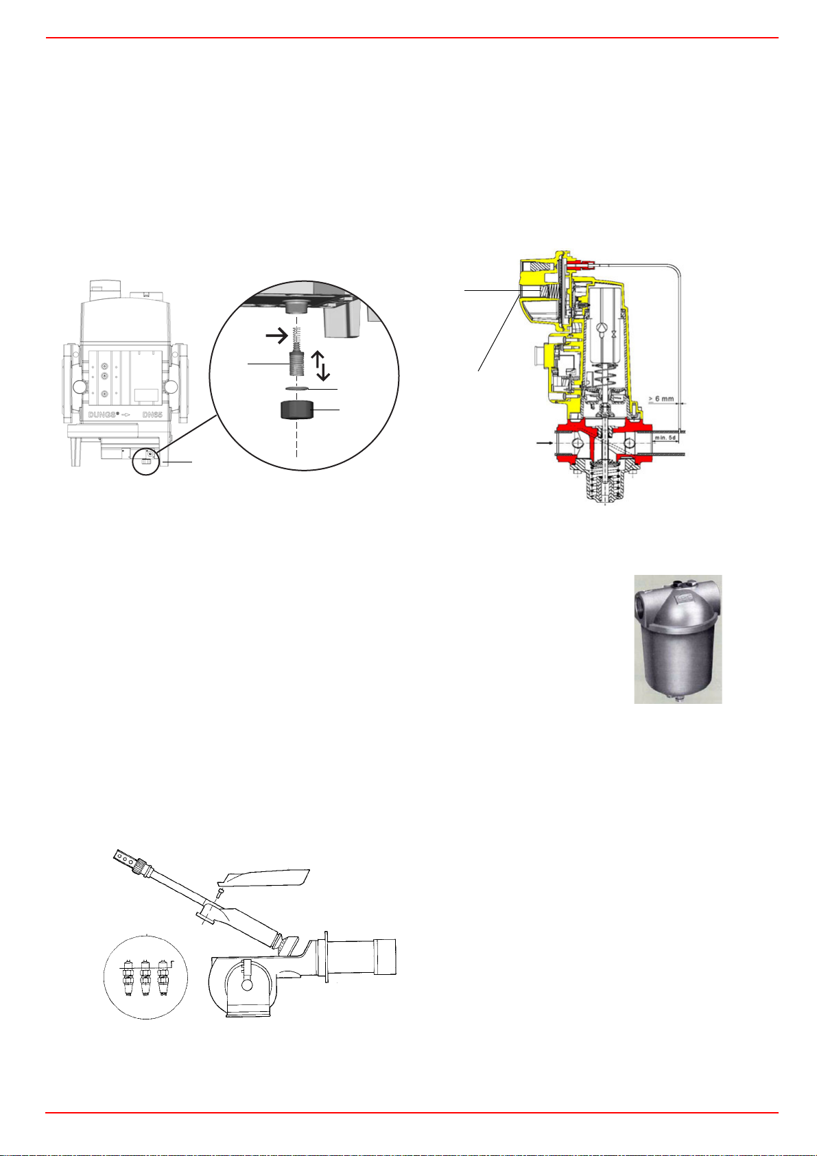
CIB UNIGAS - M039180CC
Replacing the spring in the gas valve group
To replace the spring in the gas valve group,proceed as follows:
1 Carefully twist the protection cap 1 and the O-ring 2.
2 remove the “set value” spring 3 from housing 4.
3 Replace spring 3.
4 Carefully insert the new “set value” spring. Pay attention to mount properly. First insert the spring part with smaller diameter in the
housing.
5 Place O-ring 2 in protective cap 1. Screw in the protective cap with the O-ring in it.
Stick the adhesive label for spring identification on the type plate.
3
4
3
1
2
1
4
1
DUNGS MBC..SE SKP Siemens actuator
Light oil filter maintenance
For correct and proper servicing, proceed as follows:
1 cutoff the required pipe section;
2 unscrew the filter cup;
3 remove the filtering cartridge, wash it with gasoline; if necessary, replace it; check the tightening
O-rings and replace them if necessary;
4 replace the cup and restore the pipe line.
Removing the combustion head
1 Remove the cover H.
2 Slide the photoresistance out of its housing.
3 Unscrew the V screws that block the gas collector G, loosen the three joints E and remove the ass.y as shown on the following picture.
4 Clean the combustion head by means fo a vacuum cleaner; scrape off the scale by means fo a metallic brush.
Note: to remount the burner, floow the same procedure in the reversed order.
Key
L
E
3
1
2
H
37
1 Inlet
2Return
3 Gun opening
E Oil piping connections
H Cover
L Oil gun
Page 38
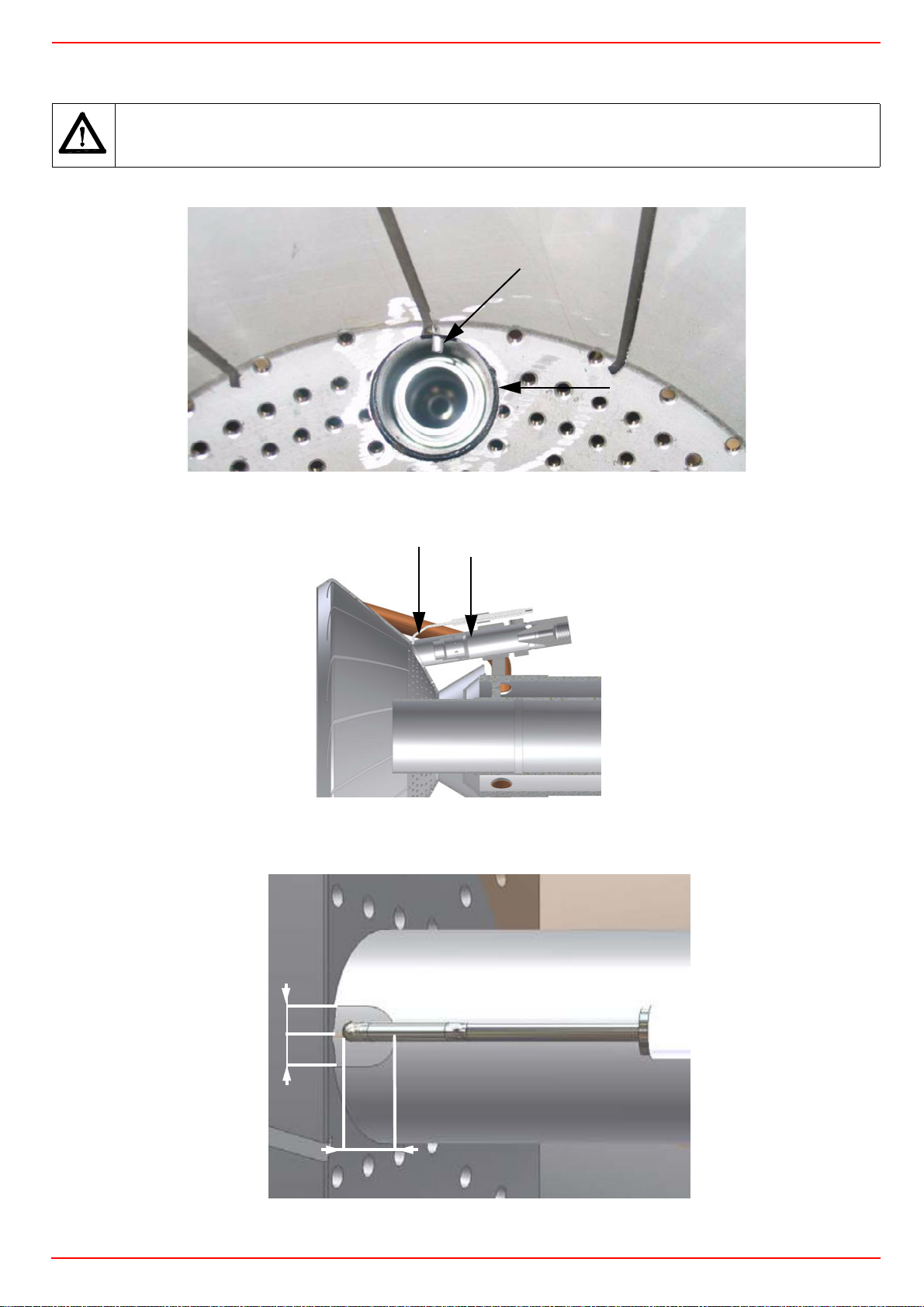
CIB UNIGAS - M039180CC
Adjusting the ignition electrode
Important Note: check the ignition electrode after each removing of the combustion head.
ATTENTION: avoid the ignition electrode to contact metallic parts (blast tube, head, etc.), otherwise the boiler’s operation
would be compromised. Check the electrode position after any intervention on the combustion head.
E
P
Fig. 29 - Detailed view of the diffuser with pilot (P) and ignition elecctrode (E)
Fig. 30 - Detailed view of the combustion head with pilot (P) and ignition elecctrode (E)
Observe the values quoted on figure.
.
E
P
P
=
=
E
5mm
Fig. 31
38
Page 39
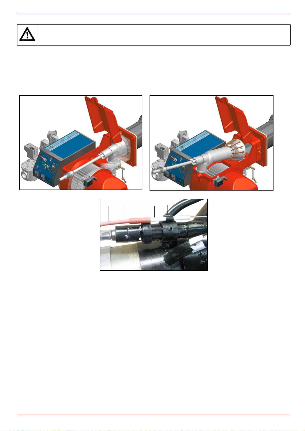
CIB UNIGAS - M039180CC
Replacing the ignition electrode
ATTENTION: avoid the ignition electrode to contact metallic parts (blast tube, head, etc.), otherwise the boiler’s operation
would be compromised. Check the electrode position after any intervention on the combustion head.
To replace the ignition electrode, proceed as follows:
1 remove the burner cover
2 disconnect the electrode (E) cable (CE);
3 remove the combustion head (see par. “Removing the combustion head”);
4 loose screw (B) that fasten the ignition electrode (E) to the burner pilot (P);
5 remove the electrode and replace it, referring to the values quoted on Fig. 31;
CE
B
P
E
39
Page 40
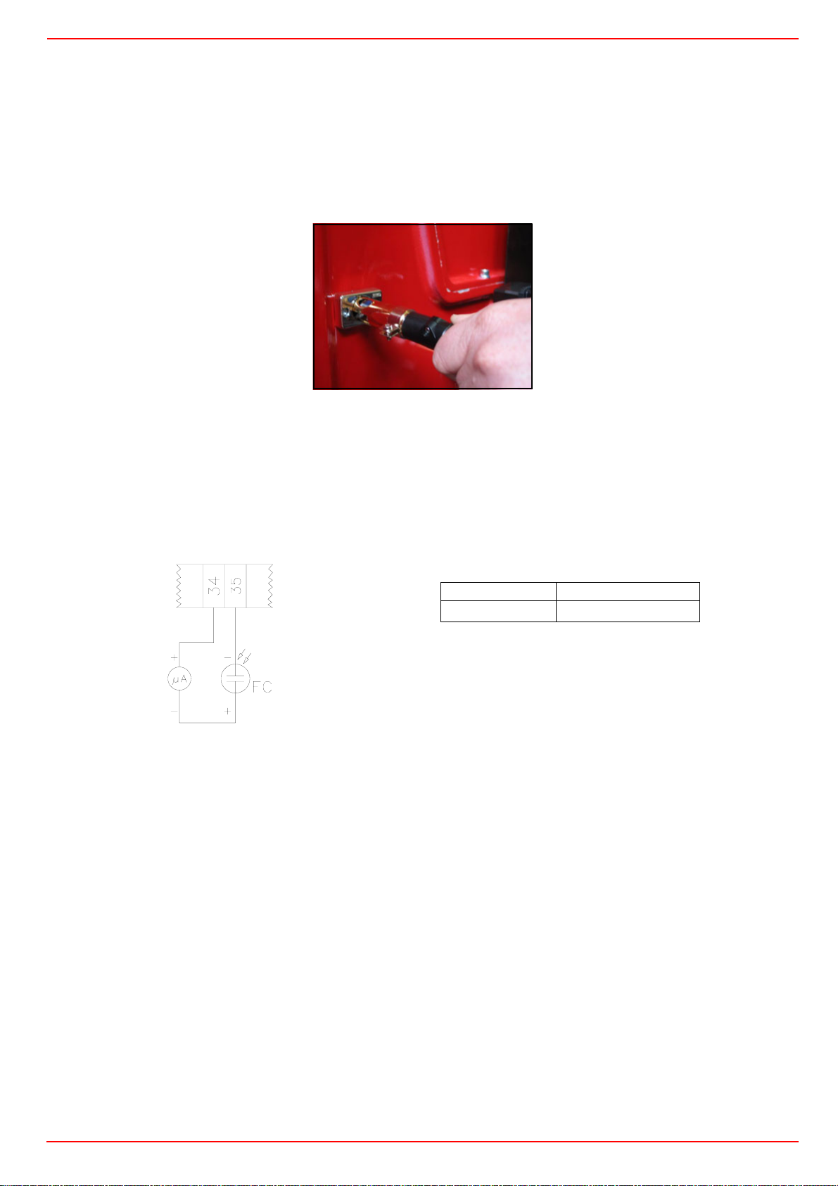
CIB UNIGAS - M039180CC
Cleaning and replacing the detection photocell
The photocell working life is about 10000 working hours (about 1 year), at max 50°C after which it must be replaced.
To clean/replace the detection photocell, proceed as follows:
1 Disconnect the system from the electrical power supply.
2 Shut off the fuel supply;
3 remove the photocell from its slot (see next figure);
4 clean the bulbe if dirty, taking care not to touch it with bare hands;
5 if necessary, replace the bulb;
6 replace the photocell into its slot.
Checking the detection current
To check the detection signal follow the scheme in Fig. 32.
If the signal is lower than the value quoted, check the position of the UV detector (photocell), the electrical contacts and, if necessary,
replace the UV detector.
TERMINAL BOARD
MC
Fig. 32: Detection by photocell QRA..
Seasonal stop
To stop the burner in the seasonal stop, proceed as follows:
1 turn the burner’s main switch to 0 (Off position)
2 disconnect the power mains
3 close the fuel cock of the supply line
Burner disposal
Control box Minimum detection signal
Siemens LFL1.3..
70µA with UV detector)
In case of disposal, follow the instructions according to the laws in force in your country about the “Disposal of materials”.
40
Page 41

TROUBLESHOOTING
CAUSE / TROUBLE
MAIN SWITCH OPEN z
LACK OF GAS z
CIB UNIGAS - M039180CC
STARTS AND
REPEATS THE
CYCLE
TO HI FLAME
DOESN’T SWITCH
OPERATION
LOCKOUT DURING
THE BURNER
DOESN’T START
PRE-PRGEe
CONTINUES WITH
AND LOCK-OUT
DOESN’T START
THE CYCLE
AND REPEATS
DOESN’T START
DURING
OPERATION
TURNS OFF AND
REPEATS CYCLE
HIGH GAS PRESSURE SWITCH
DEFECTIVE
DEFECTIVE THERMOSTAT z
OVERLOAD TRIPPED INTERVENTION z
AUXILIARIES FUSES INTERRUPTED z
DEFECTIVE AIR PRESSURE SWITCH z
DEFECTIVE CONTROL BOX zz z
DEFECTIVE ACTUATOR zzz z
AIR PRESSURE SWITCH FAULT OR
BAD SETTING
GAS PRESSURE SWITCH BAD SETTING z
IGNITION TRANSFORMER FAULT zzz z
DETECTION ELECTRODE BAD
POSITION
BUTTERFLY VALVE BAD SETTING z
DEFECTIVE GAS GOVERNOR zzz z
z
z
z
DEFECTIVE HI-LO FLAME
THERMOSTAT
ACTUATOR CAM WRONG SETTING z
PHOTODETECTOR FAULT OR WRONG
SETTING
z
z
41
Page 42

CIB UNIGAS - M039180CC
SPARE PARTS
Desription Code
HTP1030 HTP1050 HTP1080
SIEMENS LDU GAS PROVING SYSTEM 2020413 2020413 2020413
SIEMENS LFL CONTROL BOX 2020448 2020448 2020448
IGNITION ELECTRODE 2080257 2080257 2080257
OIL FILTER 2090018 2090018 2090018
GAS FILTER DN80 2090112 - -
GAS FILTER DN100 2090113 2090113 2090113
GAS FILTER DN125 2090128 2090128 2090128
AIR PRESSURE SWITCH DUNGS GW50 A6 2160085 2160085 2160085
GAS PRESSURE SWITCH DUNGS GW500 A6 2160088 2160088 2160088
GAS PRESSURE SWITCH DUNGS GW500 A5 2160089 2160089 2160089
IGNITION TRANSFORMER 2170301 2170301 2170301
PUMP MOTOR 2180257 2180257 2180257
GAS VALVE GROUP SIEMENS VGD.. DN80 2190169 2190169 2190169
GAS VALVE GROUP SIEMENS VGD.. DN100 2190174 2190174 2190174
GAS VALVE ACTUATOR SKP15 2190181 2190181 2190181
GAS VALVE ACTUATOR SKP25 2190183 2190183 2190183
GAS VALVE GROUP SIEMENS VGD.. DN125 2190184 2190184 2190184
GAS VALVE GROUP DUNGS MBC3100SE DN80 21903M7 21903M7 21903M7
GAS VALVE GROUP DUNGS MBC5000SE DN100 21903M8 21903M8 21903M8
PILOT GAS ELECTROVALVE 2190502 2190502 2190502
OIL SOLENOID VALVE - PARKER 2190750 2190750 2190750
OIL SOLENOID VALVE - L338 2190437 2190437 2190437
GAS PROVING SYSTEM VPS504 2191604 2191604 2191604
FLEXIBLE HOSE L=1500 2340004 2340004 2340004
FLEXIBLE HOSE L=600 2340059 2340059 2340059
FLEXIBLE HOSE L=385 2340088 2340088 2340088
FLEXIBLE HOSE L=435 2340089 2340089 2340089
FLEXIBLE HOSEL L=300 234FX03 234FX03 234FX03
GAS FLEXIBLE HOSE 234FX07 234FX07 234FX07
FLEXIBLE HOSE L=347 234FX24 234FX24 234FX24
FLEXIBLE HOSE L=485 234FX31 234FX31 234FX31
SMALL ADJUSTING CAM FOIL 2440013 2440013 2440013
BIG ADJUSTING CAM FOIL 2440014 2440014 2440014
ACTUATOR 2480004 2480004 2480004
UV PROBE 2510001 2510001 2510001
BURNER MODULATOR 2570112 2570112 2570112
LIGHT OIL GOVERNOR 2570006 2570008 2570008
SUNTEC TV LIGHT OIL GOVERNOR 2570036 2570036 2570036
PUMP 2590159 2590159 2590159
NOZZLE - FLUIDICS 2610203 2610203 2610203
NOZZLE - BERGONZO B 2610210 2610210 2610210
NOZZLENOZZLE - BERGONZO C 2610213 2610213 2610213
PRESSURE GOVERNOR WITH FILTER 2800085 2800085 2800085
COMBUSTION HEAD 3060277 3060292 3060292
BLAST TUBE 30910N9 30910Q9 30910Q8
IGNITION CABLE 6050010 6050010 6050010
NOTE: it is recommended to mention the burner ID number on the spare parts request form.
42
Page 43
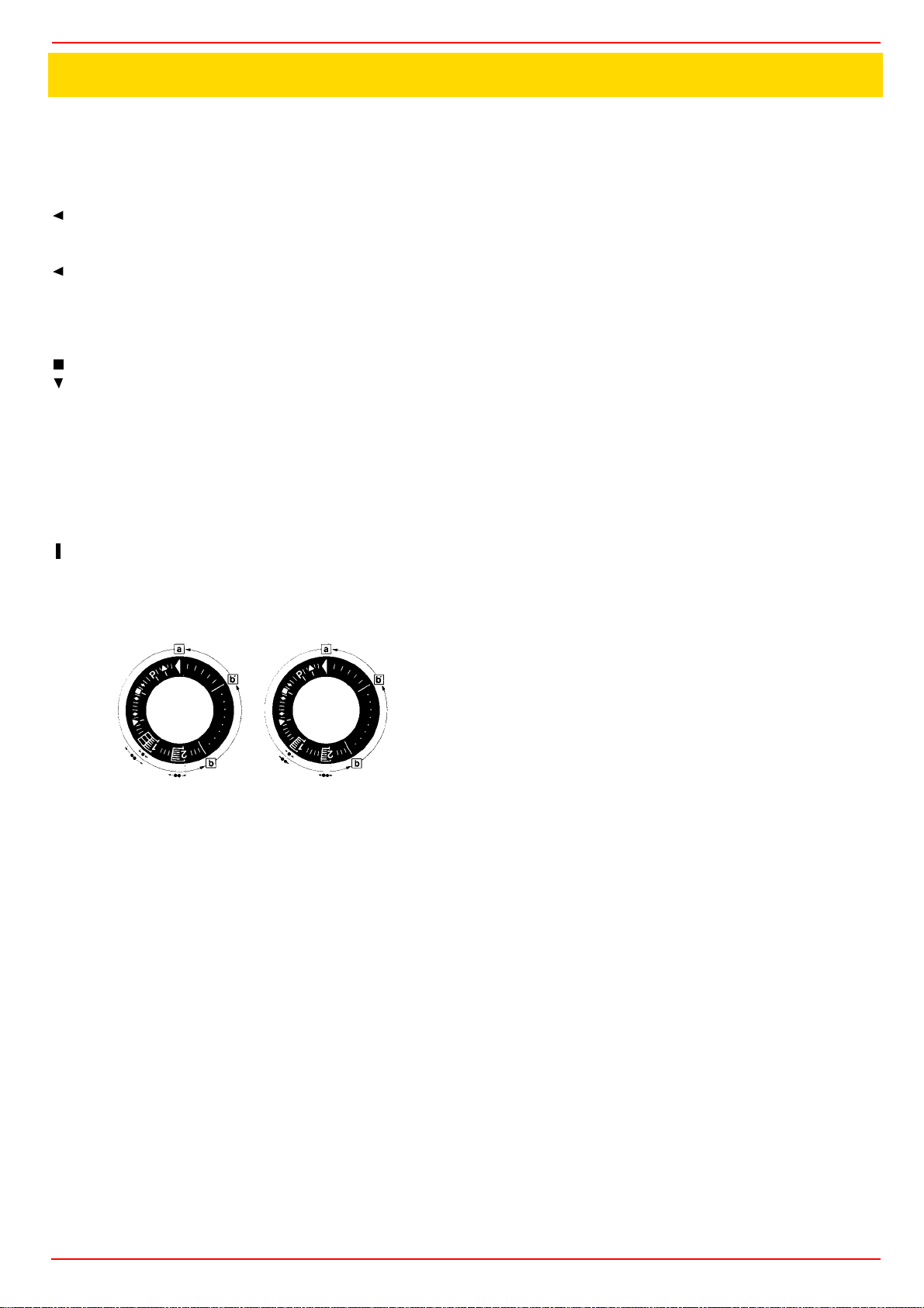
APPENDIX
SIEMENS LFL 1.3.. CONTROL BOX
Automatic programme in the event of interruption and indication of position when interrupted
By default, in the event of any kind of interruption, the flow of fuel is immediately interrupted. At the same time the programmer stops and this indicates the position at the time of the interruption.
A symbol on the indicator disc shows each time the type of stoppage:
No start-up (for example fault in the CLOSED signal for the
limit contact "Z" at terminal 8 or some other contact between
the terminals 12 and 4 or 4 and 5 is not closed).
Start-up suspended because of a fault in the OPEN signal
for the limit contact "A" at terminal 8.
P
Block due to absence of air pressure signal. From this
moment onwards any absence of air pressure will cause a
block.
Block due to malfunction of the flame detector circuit.
Start-up interrupted because there is a fault in the MINMUM
signal for the auxiliary contact of the damper servo motor at
terminal 8.
1
Block due to absence of flame signal at the end of the 1st
safety period.
From this moment onwards any absence of a flame signal will cause a
block.
2
Blockdue to absence of flame signal at the end of the 2nd
safety period (flame signal of main burner).
Blockdue to absence of flame signal or air pressure during
operation.
Where a block stoppage occurs at any moment between switch on and
pre-ignition without registering any symbol, the cause is normally an
unscheduled flame signal.
a-b Start-up programme
b-b' For time variants:move the programmer on to the automatic stop
after the burner starts up (b' = position of the programmer during normal
burner operation).
b(b')-aPost-ventilation programme after a regulation stop.At the start-up
position "a" the programmer stops automatically.
. Safety time duration for mono-tube burners
.. Safety time duration for twin-tube burners
The apparatus can be reset immediately after a block. After resetting (and
after the elimination of any problem causing the stoppage or after a power
failure) the programmer returns to its start-up position. In this event only
the terminals 7, 9, 10 and 11 are live in accordance with the monitoring
programme. Only after this the device programs a new startup.
Operation
The wiring system and also the control system of the programmer "P"
have already been given in this manual. The response signals required
for the active parts and the flame monitor circuit are shown by a hatching.
In the absence of these response signals the mechanism interrupts the
start-up programme; the exact time of the interruption can be identified
from the visual indicator and will cause a block if the safety code requires
it.
A consent to start-up by means of the thermostat or pressostat "R"
A-B start-up program
B-C normal burner operation
C regulation stop caused by "R"
C-D programmer returns to start-up position A.
During the regulation stop only terminals 11 and 12 are live and the dam-
per, through the limit contact "Z" of its servo-motor is in the CLOSED position.The flame detector circuit F is activated (terminals 22 and 23 or 23/4)
for the detector test and the paracitic light test.
Where the burners do not have dampers (or have an independent 00
damper control mechanism) there must be a bridge between terminals 6
and 8, otherwise the mechanism will not start up the burner.
For a burner to start up the following conditions must be met:
z Mechanism not blocked/reset.
z Damper closed.Limit contact switchZ must be in the CLOSED position
and allow current to flow between terminals 11 and 8.
z Any contacts checking that the fuel valve (bv...) is closed, or other con-
tacts with similar functions, must be closed between terminal 12 and
the air pressostat LP.
z The contact for the air pressostat LP must be in the off position (LP
test) so as to feed terminal 4.
z The gas pressostat contacts GP and the safety thermostat and pres-
sostat contacts W must also be closed.
Start-up program
A Start-up
(R closes the start-up control ring between terminals 4 and 5)
The programmer starts up.At the same time the ventilator motor is fed
through terminal 6 ( only for pre-ventilation) and, after t7, the ventilator
motor or the combustion gas exhaust fan is fed through terminal 7 (preventilation and post-ventilation).
At the end of t16, the command opening the damper passes through terminal 9; during the damper opening time the programmer does not move
since terminal 8, through which the programmer is fed, is dead.
Only once the damper is fully open and the limit contact switch A has
switched on, feeding terminal 8, does the programme proceed.
t1 Pre-ventilation time with damper fully open (nominal air flow).
Shortly after the beginning of the pre-ventilation time, the air pressostat
should switch off the current between terminals 4 and 13;otherwisethe
apparatus would block (air pressure monitor).
At the same time the terminal 14 should be live since current feeding the
ignition transformer and the fuel valves passes through this circuit.
During pre-ventilation time the flame detector circuit is checked and in the
event of an operational defect the monitor brings about a block.
At the end of the pre-ventilation time the monitor automatically moves the
damper servo-motor, through terminal 10, to the flame ignition position
which is governed by the auxiliary contact "M".
During this period the programmer stops until terminal 8, is again activatedthrough contact "M".
After a few seconds the little programmer motor is directly fed by the
active part of the apparatus.
After this point terminal 8 plays no further part in the burner ignition process.
Mono-tube burner
t3 Pre-ignition time waiting the response from the fuel valve at terminal 18.
t2 Safety time (start up flame strenght); at the end of the safety time a
flame signal should appear at terminal 22 of the amplifier and it should
stay on until a regulation stop; if this does not happen the mechanism will
block.
t4 Interval; at the end of t4, terminal 19 is live.
t5 Interval At the end of t5 terminal 20 is live.At the same time the
monitor outlets from 9 and 11 and terminal 8 into the active part of the
apparatus are kept galvanically separatedso as to protect the monitor
itself from recovery voltage through the capacity regulator circuit.
Page 44

Twin-tube burners (**)
t3 Preignition time until the all clear to the pilot burner valve at
terminal 17.
t2 First safety time (pilot flame strenght); at the end of the safety time
a flame signal should appear at terminal 22 of the amplifier and it should
stay on, until a regulation stop; if it does not, the apparatus will block.
t4 Interval until the consent to the fuel valve at terminal 19, for the first
flame of the main burner.
t9 2nd safety time; at the end of the second safety time the main burner should be lit by means of the pilot. At the end of this period, terminal
17 is dead and therefore the pilot burner will be out.
t5 Interval; at the end of t5 terminal 20 is live. At the same time the
monitor outlets from 9 to 11 and the terminal 8at the input of the active
part of the apparatus are galvanically separated so as to protect the apparatus itself from recovery voltage through the strenght regulator circuit.
When the strenght regulator LR at terminal 20 gives the consent,
the start-up programme for the apparatus comes to an end. Depending on
time variants, the programmer stops either immediately or at the end of a
set time, without effecting the position of the contacts.
B Operational position of the burner
B-C Burner operation (production of heat)
While the burner is working the strnght regulator controls the damper,
according to the demand for heat, by means of the positioning at nominal
load of the auxiliary contact "V" of the damper servocontrol.
C Regulation stop for operation of "R"
When there is a regulation stop the fuel valves immediately close. At the
same time the programmer starts to programme:
t6 Post-ventilation time (post-ventilation with the ventilator "G" at ter-
minal 7).Shortly after beginning of the post-ventilation time terminal 10
becomes live and moves the damper to the "MIN" position. The full closure of the damper only happens towards the end of the post-ventilation
time and is prompted by an automatic signal from terminal 11
t13 Admissible post-ignition time
During this time the flame monitor circuit may still receive a flame signal
without the apparatus blocking.
D-A End of automatic programme
At the end of t6, at the point where the programmer and the automatic
contacts have reverted to the starter position, the detection probe test
restarts.
During an operational stop even an unscheduled flame signal lasting a
few seconds can cause a block because during this period an NTC in the
circuit acts as retarder.This means that brief unscheduled influences cannot cause a block.
(**) Times t3, t2 and t4 only apply only to safety devices in the series 01.
Specifications
Mains voltage 220V -15%...240V +10%
Frequency 50Hz -6%...60Hz +6%
Absorbed capacity 3.5 VA
Built-in fuse T6.3/250E slow action DIN41571 No.
451915070
External fuse max. 16A
Interference N-VDE0875
Flow permitted at terminal 1 5A (DIN 0660 AC3)
Flow permitted at control terminals
4A (DIN 0660 AC3)
Flow at monitor contacts:
input at terminals 4 & 5 1A, 250V
input at terminals 4 & 11 1A, 250V
input at terminals 4 & 14 function of the load at terminals 16 and
19, min.1A, 250V
Emplacement Any
Protection IP40
Permitted ambient temp -20...+60° C
Min.temperature (trans/storage) -50° C
Weight:
apparatus approx. 1,000g.
base approx. 165g.
Ionisation monitor
voltage in detector electrode
normal working 330V ±10%
test 380V ±10%
short circuit current max. 0,5 mA
Ionisation current, min.request 6 µA
max. permitted length for connecting cables
normal cable (laid separately**) 80m
armoured cable(high frequency) protection at terminal 22
140m
UV monitor
Voltage in UV detector
normal working 330V ±10%
test 380V ±10%
Detector current, min. request* 70µA
Max. detector current
normal working 630 µA
test 1300 µA
Max.length of connecting cable
normal cable (laid separately**) 100m
armoured cable (high frequency) protected at terminal 22
200m
Weight
QRA2 60 g
QRA10 450 g.
*Connect up in parallel to the measuring device a condenser 100µF,
10...25V.
** The wire connecting up the detector electrode should not be in the
same sleeve as the other conductor wires.
Ignition spark monitor with QRE1 series 02 detector
Minimum detector current 30µA
Operating times
t7 initial delay for ventilator G2 2
t16 initial delay of air damper OPEN consent 4
t11 opening time for damper any
t10 initial delay for air pressure monitor8
t1 pre-ventilation time with damper open36
t12 travel time for air damper to MIN positionany
t3 t3' pre-ignition time t3 4
t3 't2 t2' safety time (1st safety time for burners with intermittent pilot
lighter t2 2
t2 't4 t4' interval between start of t2 and response to valve at terminal 19
t4 10
t4 't9 2nd safety time for burners with intermittent pilot lighter 2
t5 interval between end of t4 and response at terminal 20 10
t20 interval before programmer cuts out after start-upduration of start-up 60
t6 post-ventilation time (G2 only) 12
t13 permitted post-ignition time 12
t16 initial delay from opening consent of the air damper
t20 interval until the automatic shut-off of the programming mechanism
after the burner start
Page 45

Key
A limit contact switch for damper OPEN position
AI block remote signal
AR main relay (working network) with contacts "ar"
AS Monitor fuse
BR block relay with "br" contacts
BV fuel valve
EK reset button
FE detector electrode of ionisation circuit
FR flame relay with "fr" contacts
G ventilator motor or burner motor
GP gas pressure switch
H main interruptor switch
L block stoppage LED
LK air damper
LP air pressostat
LR safety regulator
M auxiliary contact switch for damper "MIN" position
QRA UV detector
QRE ignition spark detector
R thermostat or pressostat
Sfuse
SA damper servo-motor
SM synchronous programmer motor
V flame signal amplifier
V in case of servo-motor: auxiliary contact for response to fuel
valve with regard of damper position
W safety pressostat or thermostat
Z ignition transformer
Z in case of servomotor: end of limit contact switch for damper
CLOSED position
ZBV pilot burner fuel valve
° for mono-tube burners
°° for twin-tube burners
Programmer diagram
t1 pre-ventilation time
t2 safety time
*t2 '1st safety time
t3 pre-ignition time
*t3 'pre-ignition time
t4 interval for creating current between terminals 18 and 19
*t4 'interval for creating current between terminals 17 and 19
t5 interval for creating current between terminals 19 and 20
t6 post-ventilation time
t7 interval between startup consent and current created at
terminal 7
t8 duration of start-up
*t9 2nd safety time
t10 interval before air pressure monitoring begins
t11 damper opening travel time
t12 damper closure travel time
t13 permissible post-combustion time
t16 initial delay of damper OPEN response
t20 interval before programmer automatically stops
* These times are valid with the use of a series 01 safety device for moni-
toring burners with intermittent pilot lighter.
(1) input for raising QRA detector voltage to test level
(2) input for excitation of flame relay during flame detector test
circuit (contact XIV) and during safety time (contact IV)
(3) Do not press EK for more than 10 seconds
Page 46
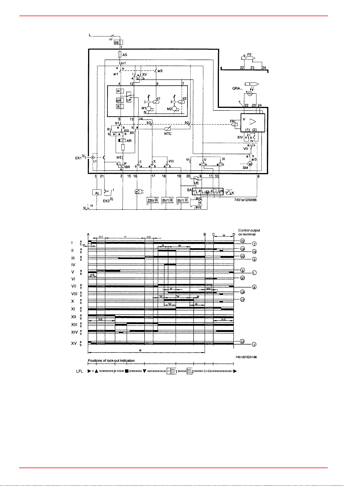
VALVE PROVING SYSTEM SIEMENS LDU11
The LDU11... gas valve proving system is designed for use in gas-fired
plant equipped with two safety shutoff valves. During each startup cycle,
the control unit automatically programs the valve proving test and, in the
event of a leak, prevents burner startup.
The LDU11… control unit is designed to provide automatic gas valve proving (leakage test) based on the pressure proving principle. It is for use in
gas-fired plant with or without vent pipe to the atmosphere. For plants
without vent pipe, where DIN/DVGW regulations apply, refer to the hints
given on "Connection examples with vent pipe to the
atmosphere".
Gas valve proving is initiated automatically with every burner startup
using one or two standard pressure monitors, either
z prior to burner startup,
z during the pre-purge time, if it lasts at least 60 s,
z immediately after the controlled shutdown, or
z on completion of the burner control's control program, e.g. on comple-
tion of the post-purge time
The valve proving test is based on the two-stage pressure proving principle: first, the valve on the mains side is tested by evacuating the test
space and by monitoring the atmospheric pressure in it. Then, the valve
on the burner side is checked by pressurizing the test space and by monitoring the gas pressure. If the pressure increases excessively during the
Page 47

first test phase (Test 1), or decreases excessively during the second test
phase (Test 2), the control unit inhibits burner startup and goes to lockout.
In that case, the lockout reset button lights up to indicate the fault.
Remote indication of the fault is also possible.
A program indicator, which stops whenever a fault occurs, indicates which
of the two valves is leaking.
Mode of operation
To carry out the first phase of the valve proving test, called "Test 1", there
must be atmospheric pressure in the length of pipe between the two valves to be tested. In plants with a vent to the atmosphere, this pressure is
available if the valve proving test isconducted prior to or during the prepurge time. In plants without a vent pipe, atmospheric pressure is made
available as the control unit opens the valve on the burner side during the
time "t4". If the valve proving test is performed after the operation of the
burner, the valve on the burner side after the controlled shutdown can be
kept open until "t4" has elapsed, thus reducing the pressure in the test
space and making certain its gas content is burnt off in the combustion
chamber during the post-purge time. A prerequisite for this procedure is
an appropriate control program of the burner control as provided by Lan-
dis & Staefa burner controls type LFE..., LFL..., LGK.... or LEC.... The test
space is closed off after it has been evacuated.
During the first test phase (Test 1) which follows immediately, the control
unit checks if the atmospheric pressure in the test space is maintained
using the pressure monitor. If the valve on the mains side is leaking, causing the pressure to rise above the switching point of the pressure monitor, the control unit initiates an alarm and goes to lockout.
The program indicator then stops and indicates "Test 1".
If the pressure does not increase because the valve closes correctly, the
control unit immediately programs the second test phase (Test 2). To do
this, the valve on the mains side is pressurized ("filling" of test space).
During the second test phase, the pressure may not fall below the
switching point of the pressure monitor due to a leak of the valve on the
burner side.
If it does, the control unit goes to lockout again, thus inhibiting burner startup.
On the successful completion of the second test phase, the control unit
closes the internal control loop between terminals 3 and 6 (circuit path:
terminal 3 - contact "ar 2" -terminals 4 and 5 - contact III - terminal 6). This
control loop is usually included in the start control loop of the burner control.
After the control loop has been closed, the programming mechanism of
the control unit returns to its start position where it switches itself off.
During these "idle steps", the position of the control contacts of the programming mechanism remains unchanged.
Program and lockout indicator
When the unit goes to lockout, the programming mechanism stops and
also the position indicator fitted to the spindle of the mechanism. The
symbol that stops above the reading mark not only indicates during which
test phase lockout occurred, but also after how many programming steps
within the test phase (1 step = 2.5 seconds).
Specifications
Mains voltage AC 220 V -15 %...240 V +10 % AC 100 V
-15 %...110 V +10 % Mains frequency 50
Hz -6 %...60 Hz +6 %
Power consumption
- during the test 3.5 VA
- during burner operation 2.5 VA
Prefuse (externally) T16/500 V
Unit fuse T6,3H250 V to IEC 127
Radio interference protection N to VDE 0875
Perm. input current at terminal 15 A continuous to VDE 0660 AC3
Environmental conditions:
Temperature -50...+60 °C
Humidity < 95 % r.h.
Mechanical conditions class 2M2
Climatic conditions class 3K5
Temperature -20...+60 °C
Humidity < 95 % r.h.
Condensation, formation of ice and influence of water are not permitted
Perm. current rating of control terminals4 A to VDE 0660 AC3
Required switching capacity of pressure switch "DW"1 A min.,
AC 250 V
Mounting position optional
Degree of protection IP40
Weight
control unit approx. 1000 g
base approx. 165 g
CE conformity According to the directives of the Euro-
pean Community
Electromagnetic compatibility EMC 89/336
EWG include. 92/31 EEC, Gas appliance directive 90/396 EEC
Emissions EN 50081-1
Immunity EN 50082-2
Start position = operating position
In plants without a vent valve: evacuation of test space
through opening of the valve on the burner side
Test 1 "Test 1" with atmospheric pressure (valve proving test on
the mains side)
Filling the test space through opening of the valve on the
mains side
Test 2 "Test 2" with gas pressure (valve proving test on the burner
side)
Idle steps until programming mechanism switches itself off
Operating position = start position for the next valve proving
test
In the event of lockout, all terminals receiving voltage from the control unit
are de-energized, except terminal 13, which is used for lockout indication.
After the unit has been reset, the programming mechanism automatically
returns to its
start position and immediately reprograms a new valve proving test.
Note: do not press the reset button for more than 10 seconds.
Control program after a power failure
A power failure prior to evacuating the test space does not cause the program sequence to change.
If a power failure occurs after the evacuation, the valve proving test will
not be continued when power is restored, but the programming mechanism first returns to its start position to reprogram the complete proving
test.
Page 48
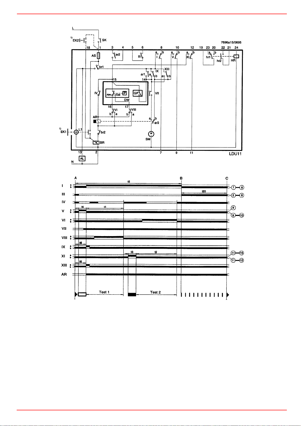
KEY
AL Alarm signal "Leaking valve"
AR Main relay with contacts "ar..."
AS Built-in fuse
BR Lockout relay with contacts "br..."
DW Pressure monitor for valve proving test (does not replace the
gas pressure monitor used to signal lack of gas)
EK... Lockout reset button
GP Gas pressure monitor (for lack of gas)
HR Auxiliary relay with contacts "hr..."
L1 Built-in lockout warning lamp
SM Synchronous motor of programming mechanism
SK Mains switch
Warning notes
z The electrical wiring must comply with local and country-specific standards and regulations!
z The LDU11... must be completely isolated from the mains before per-
forming any work on it!
z The LDU11... is a safety device. It is therefore not permitted to open,
interfere with or modify the unit!
z Check wiring carefully before putting the unit into operation!
z Check all safety functions when putting the unit into operation or after
replacing a fuse!
z Ensure protection against electric shock hazard on the unit and at all
electrical connections through appropriate mounting!
z Electromagnetic emissions must be checked from an application point
of view!
z The regulations and standards covering the specific application must
be observed!
z All installation and commissioning work must be carried out by qualified personnel!
z In the geographical areas where DIN standards are in use, the installation must be in compliance with VDE requirement, particularly with the
standards DIN/VDE 0100 and 0722!
z Condensation and ingress of humidity must be avoided!
z Ignition cable must always be laid separately, observing the greatest
possible distance to other cables!
Page 49

Page 50

Page 51

Page 52

C.I.B. UNIGAS S.p.A.
Via L.Galvani, 9 - 35011 Campodarsego (PD) - ITALY
Tel. +39 049 9200944 - Fax +39 049 9200945/9201269
web site: www.cibunigas.it - e-mail: [email protected]
Note: specifications and data subject to change. Errors and omissions exceptd.
 Loading...