

Page 1

OPERATING MANUAL
- HM 200
- HM 200 Ecoline
- HM 200 Ecoline DC
- HM 250
- HM 260
Technical Details subject to change EN
Copying and distributing this document and the use or communication of the contents thereof are forbidden without
expressed authority. Offenders are liable to the payment of damages. All rights are reserved in the event of the grant of a
patent or the registration of a utility model or design.
Page 2

,
CE-Declaration of Conformity
within the meaning of Directive Machines 2006/42/EC.
The following machine
HM 200 / HM 200 Ecoline / HM 200 Ecoline DC
HM 250
HM 260
was developed, designed and manufactured in accordance with Directive 2006/42/EC under the sole responsibility
of
Company
UNIFLEX - Hydraulik GmbH
Robert-Bosch-Straße 50 - 52
D - 61184 Karben
Documentation officer Carsten Baumgartner
The following standards, directives and specifications were applied:
• EG-Richtlinie 2006/42/EG - Directive 2006/42/EEC
• EG-Richtlinie 2014/35/EU - Directive 2014/35/EEC
• EMV Richtlinie 2014/30/EU - EMC Directive 2014/30/EEC
• EN ISO 12100: 2010
• EN 60204: 2006
If the machine is changed in any way without consulting us beforehand or if any non-tested and non-accepted
outside parts are used, this declaration shall lose its validity.
Complete technical documentation is available.
This Operating Manual of the machine is a translation; the original version is in German.
Karben
---------------------------------- -------------------------------------- ---------------------- ----------------
21. Juni 2016
Place, Date Signature Function of the signee
Geschäftsführer / /
Gérant /
UNIFLEX-Hydraulik - 2 - www.uniflex.de
Page 3

CE-Declaration of Conformity ................................................................................................................................................ 2
Chapter 1 Introduction ............................................................................................................................................. 5
General information regarding the operating instructions .............................................................................................. 5
Safety and accident prevention ...................................................................................................................................... 5
Pictograms ..................................................................................................................................................................... 5
Chapter 2 Security .................................................................................................................................................. 6
Safety ................................................................................................................................................................................. 6
Safety information provided in the Operating manual .................................................................................................... 6
Obligations of the owner ................................................................................................................................................ 6
Obligations of the personnel .......................................................................................................................................... 6
Hazards when operating the machine ............................................................................................................................ 6
Usage to the intended purpose ...................................................................................................................................... 7
Warranty and liability ...................................................................................................................................................... 7
Informal Security Measures ........................................................................................................................................... 7
Training of the personnel ............................................................................................................................................... 7
Control of the hose crimper ............................................................................................................................................ 7
Safety measures for normal operation ........................................................................................................................... 7
Hazards caused by electrical energy ............................................................................................................................. 7
Dangers of hydraulic oil .................................................................................................................................................. 7
Maintenance and servicing, trouble-shooting ................................................................................................................. 7
Constructional modifications of the machine .................................................................................................................. 8
Cleaning the machine and waste disposal ..................................................................................................................... 8
Safety installations ......................................................................................................................................................... 9
Emergency switch (if applicable) ................................................................................................................................ 9
Security installations ...................................................................................................................................................... 9
Safety-switch back stop (if applicable) ........................................................................................................................... 9
Path limitation ................................................................................................................................................................. 9
Hazards and safety measures ....................................................................................................................................... 9
Personal safety .............................................................................................................................................................. 9
Chapter 3 Description of the system ........................................................................................................................ 10
Design .............................................................................................................................................................................. 10
Technical Details HM 200 Ecoline, HM 200 Ecoline DC, HM 200, HM 250, HM 260 .................................................. 11
Chapter 4 Commissioning ..................................................................................................................................... 12
Unpacking / set up ....................................................................................................................................................... 12
Hydraulic Power Unit – Only ECOLINE DC: ................................................................................................................ 13
Filling with hydraulic oil ................................................................................................................................................ 13
Ventilate the Hydraulic System .................................................................................................................................... 13
Connecting the electric supply ..................................................................................................................................... 14
HM200Ecoline Connecting the electric supply ............................................................................................................. 15
Connecting the electric supply (Ecoline DC only) ........................................................................................................ 16
Chapter 5 Crimping .............................................................................................................................................. 17
Quick die change QDC 239.5 .......................................................................................................................................... 17
Insert the crimp dies 239 / 239L in the machine .......................................................................................................... 17
Take the crimp dies 239 / 239L out of the machine ..................................................................................................... 17
Set the crimp diameter / Crimp die table PB 239 ......................................................................................................... 18
General Notes for Crimping ......................................................................................................................................... 19
Control of the hose crimper .......................................................................................................................................... 19
Chapter 6 Maintenance ......................................................................................................................................... 20
Daily Maintenance works ............................................................................................................................................. 20
Monthly maintenance ................................................................................................................................................... 20
Six-month maintenance ............................................................................................................................................... 20
Annual maintenance .................................................................................................................................................... 20
Calibrate the crimp micrometer .................................................................................................................................... 21
Exchange Slide Bearings ............................................................................................................................................. 22
UNIFLEX-Hydraulik - 3 - www.uniflex.de
Page 4

_ Anhang / Appendix / Apéndice / Appendice ....................................................................................................... 23
Ersatzteilliste / Spare Parts List / Pièces détachées / Lista de piezas de recambio ........................................................ 23
Haltebolzen für Standard Pressbacken / Pins for standard dies / Tourillon de mors standard / Gorrón de mordza
estándar ........................................................................................................................................................................... 30
Wo Sie Ersatzteile bestellen können / Where to obtain spare parts / .............................................................................. 31
Adresse pour nous contacter / La dirección para encargar piezas de recambio: ............................................................ 31
HM 200 Ecoline ............................................................................................................................................................ 32
Elektro- & Hydraulikplan / Electric & Hydraulic Circult Diagram ................................................................................... 32
HM 200 Ecoline ............................................................................................................................................................ 33
Elektroplan für Unteröl-Aggregat PUU 45L 3.0_04/ Electric Circuit Diagram for Aggregate under oil PUU 45L 3.0_04
(440V-60Hz-3~) ........................................................................................................................................................... 33
HM 200 ......................................................................................................................................................................... 34
Elektroplan (Steuerteil) / Electric Circuit Diagram (Control Part) ................................................................................. 34
HM 200 ......................................................................................................................................................................... 35
Elektroplan (Leistungsteil) / Electric Circuit Diagram (Power Section) ......................................................................... 35
HM 250 / HM 260 ......................................................................................................................................................... 36
Elektroplan / Electronic Circuit Diagram (480V 50/60Hz 3P) ....................................................................................... 36
HM 250 / HM 260 ......................................................................................................................................................... 37
Elektroplan / Electric Circuit Diagram (220/239V 50/60Hz 3Ph) ................................................................................. 37
HM 200 / HM 250 / HM 260 ......................................................................................................................................... 38
Hydraulikplan / Hydraulic Diagram ............................................................................................................................... 38
HM 200 / HM 250 / HM 260 ......................................................................................................................................... 39
Wartungsbuch / Maintenance book / Carnet d’entretien / Libro de mantenimiento / Libretto die manutenzione /
Onderhoud boek .......................................................................................................................................................... 40
Erklärung des geschulten Personals / Declaration of Trained Personnel .................................................................... 41
Gültig seit: 21.06.16
Änderungszustand: t
Erstellt: Jarrasch
Genehmigt
UNIFLEX-Hydraulik - 4 - www.uniflex.de
Page 5

Chapter 1 Introduction
General information regarding the operating instructions
This operating manual forms part of the scope of delivery of your UNIFLEX machine and it is intended for the user
and maintenance / service staff.
The manual describes how the hose crimper works, provides information on hazards that may arise during its
operation, contains detailed information on how to operate the machine, and describes the steps necessary for
servicing and checking the accuracy of the hose crimper. Even if you have attended a training course for op erating
this machine, please read these operating instructions completely before starting up the machine.
By signing your name on the last page >Appendix<, you confirm that you have read completely and understood
this Operating Manual. The owner of the machine shall be obliged to only let such persons operate and ca rry out
maintenance work on the hose crimper, who satisfy the above-mentioned prerequisite.
Safety and accident prevention
This hose crimper is a state-of-the-art machine and it is safe to use. Nonethel ess, certain rules have to be
observed to minimize the risk of injuries and protect the machine.
Please pay particular attention to Chapter 2 >Safety< in these operating instructions.
Pictograms
This pictogram indicates texts providing useful information on the application of the machine and
how it can be handled and used op timally.
This symbol points out cri tical poin ts, which can lead to damage of the machine , incorrect
functioning, or faulty produc tion.
This symbol points out hazards to life and health as well as risks of injuries.
This symbol refers to haza rds aris ing during the crimping process.
UNIFLEX-Hydraulik - 5 - www.uniflex.de
Page 6

Chapter 2 Security
Safety
Attention:
Serious accidents may occur if the mac hine is handled inco rrectly.
Safety information provided in the Operating manual
All rules and regulations regarding the prevention of accidents, which are applicable at the place of use, h ave to be
observed.
Obligations of the owner
The owner undertakes to only let such persons work on the machine who are familiar with the basic regulations on
work safety and accident prevention, have been instructed in the operation of the hose press, and have read and
understood the operating manual. The owner shall check at regular intervals whether the personnel is ope rating the
machine according to the safety regulations.
Obligations of the personnel
All persons authorized to work with this Uniflex machine are obliged to observe the basic regulations on work
safety and accident prevention and read the operating manual.
Hazards when operating the machine
This machine has been constructed according to state-of-the-art engineering and acknowledged safety regulations.
Nonetheless, dangers can arise for the operator and third persons. Additionally the machine and/or other property
can be damaged during incorrect operation. The machine may therefore only be used:
for its proper purpose and intended use,
when it is in perfect and safe working order.
Any faults have to be remedied immediately.
Compliance with all existing safety guidelines is mandatory for the safe operating of the hydraulic press.
Necessary slits for inserting the workpiece must be minimized by limiting the opening strok e.
Due to the diversity of changing, customized workpieces it is not possible for Uniflex Hydraulik to include
additional safety devices in the machine’s delivery that could avert any remaining dangers resulting from
the machine.
The operator must check the necessity for additional safety devices, tailored to the workpiece, before
putting the machine into operation. This may for example, become necessary for angled workpiece
geometries that require a large opening of the press for insertion.
If additional safety devices become necessary, they must be installed prior to commissioning to ensure the
continuous safety of the operator.
We particularly point out that the machine may only be used for its intended purpose. Especially non-metal
workpieces can, by the pressing procedure, be stressed in such a manner that this may lead to a sudden
failure of the material. Chips or strongly accelerated workpiece parts also present a high potential risk of
danger for the operator and persons and objects even beyond the work area.
On request Uniflex Hydraulik can provide individual solutions for safety devices. For a consultati on please
contact your personal contact partner.
UNIFLEX-Hydraulik - 6 - www.uniflex.de
Page 7

Usage to the intended purpo se
This UNIFLEX machine is designed only for crimping hose assemblies. Any other usage or any usage exceeding
the tasks described above shall not be considered usage to the intended purpose. Operating the machine in a
potentially explosive atmosphere is prohibited.
The object to be pressure-joined must be positioned in the tool centre in order to achieve good conicity and a long
machine lifetime.
Usage to the intended purpose also includes the observance of all information and instructions provided in the
operating manual and the timely execution of the inspection and maintenance work.
Note:
Other types of application are only permissible fol lowing prior co nsultation wi th the manufactu rer!
Warranty and liability
As a rule our "General Terms and Conditions of Sale and Delivery" shall apply. These are available to the buyer on
demand. Warranty and liability claims for injuries to persons and/or damage to property shall be excluded if such
claims can be attributed to one or several of the causes listed below:
Use of the machine not to the intended purpose.
Improper assembly, start up, operation and/or maintenance/repair of the machine.
Operation of the machine without the protective coverings being mounted correctly.
Non-observance of the information concerning the transport, storage, assembly, start up, operation and
maintenance of the machine provided in the operating manual.
Unauthorized constructional changes on the machine.
Unauthorized modification of programs that affect the control of the machine.
Inadequate inspection of wearing parts.
Incorrectly performed repair work.
Emergencies due to external causes and/or force majeure.
Improper work on automatic-program P3 with the pedal switch or back stop (if applicable)
Informal Security Measures
The operating manual needs to be at the location of the machine at all times. Additionally to the operating manual
the local regulations for accident prevention and environmental protection need to be available and they need to be
observed. All safety notes and danger indication need to be kept in legible condition.
Training of the personnel
Only adequately trained and instructed personnel should be authorized to work on the machine. The
responsibilities of the personnel as to the assembly, start up, operation, maintenance and repair of the machine
should be clearly defined. Personnel undergoing training should only work at the machine und er the supervision of
an experienced person.
Control of the hose crimp er
Warning:
Under no circumstances may the control system be modified in any way!
Safety measures for normal operation
The machine must only be operated when all protective coverings have been mounted correctly. Prior to switching
on the machine it must be certain that no one can be injured or endangered by the working machine. Inspect the
outside of the machine at least once during every shift to check for any damages.
Hazards caused by electrical energy
Only qualified electricians should carry out work on the electric power supply. The electrical components of the
machine need to be checked at regular intervals. Any loose connections and damaged cables should b e repaired
immediately. The housing must always be kept closed and access should only be permitted to authorized
personnel.
If works are needed on any electrical components of the machine, a second person must take
part to activate the main switch in case of an emergency.
Dangers of hydraulic oil
Be sure to prevent any hydraulic oil from seeping into the ground, water and/or sewage system. Hydraulic oil is not
water soluble and hardly biologically degradable. Therefore hydraulic oil is water polluting according to the German
Water Resources Management Law (WHG, WHG 1). Avoid long and intensive skin contact.
Maintenance and servicing, trouble-shooting
Carry out prescribed maintenance work in time. Inform the operating personnel before you begin with the
maintenance and servicing work. Always make sure that the machine is off circuit when any maintenance,
UNIFLEX-Hydraulik - 7 - www.uniflex.de
Page 8

inspection or repair work is to be carried out and that the main switch cannot be switched on unexpectedly (i.e. by
securing it accordingly). Put up a warning sign prohibiting any third persons from starting up the machine. Mount all
protective and safety guards again as soon as the maintenance work has been completed and check that all
screwed connections are fastened.
Constructional modifications of the mach ine
The machine may not be modified and no parts may be built on or modified without the manufacturer’s approval.
Any modifications need to be confirmed in writing by UNIFLEX-Hydraulik GmbH. Any parts that are not in perfect
working order should be replaced immediately. Only original spare parts and wearing parts should be used. It
cannot be guaranteed that other parts are designed and manufactured in such a way that they will meet the load
and safety requirements.
Cleaning the machine and waste disposal
All substances and materials used have to be handled and disposed of properly, in particular when work with
lubricants was carried out. The national regulations on waste disposal have to be observed.
UNIFLEX-Hydraulik - 8 - www.uniflex.de
Page 9

Safety installations
Emergency switch (if applicable)
Note:
the emergency switch must be activate d in all situa tions where injuries of people or damage on
the machine can arise:
The emergency switch is located on the control board.
Security installations
Before each use of the crimping machine or the system, all safety installations must be fitted and working correctly.
Authorized personnel may only remove safety installations:
After the complete stop of the machine.
After safeguarding against accidental switching on.
In the case of partial delivery of components the provided safety instructions and notes need to be displayed
correctly by the user.
Safety-switch back stop (if applicable)
For safety reasons the back stop stops whenever during the crimping process the hose no longer touches the back
stop.
Path limitation
Adjust the opening diameter of the crimping tool so that it exceeds the diameter of the hose fitting only fractional.
This setting protects the operator from reaching into the crimping area with his or her hand.
Hazards and safety measures
Personal safety
Irrespective of the local accident prevention regulations, the following instructions should be observed as a mean s
of protecting the health and safety of the maintenance and operating personnel:
Never reach into the machine with your hands during operation.
Always keep a copy of the operating manual at the place of use of the machine.
Make sure that all safety and danger notices on the machine (if applicable) are always legible.
Only operate the machine when all safety devices are in working order.
Before starting up the hydraulic unit, make sure that the running machine can endanger no one.
Do not place any objects on the floor near the workplace.
Wear working gloves, especially when heavy work pieces have to be loaded.
Do not bring work materials to the machine with a fork lift truck.
Wear safety shoes.
Danger:
Never reach into the crimp tool with yo ur hands while the elec tric motor is running ! Always mak e
sure that there is an adeq uate safe ty distance of at least 12 0 mm to the crimp tool when you are
inserting a hose fitting.
Warning:
Switch off the machine using the main switch during all main tenance and setting works!
Danger:
When the machine is handled improperly, there is the danger of hands getting caught and
crushed!
UNIFLEX-Hydraulik - 9 - www.uniflex.de
Page 10

Chapter 3 Description of the system
Design
HM 200 Ecoline /
HM 200 Ecoline DC
1 Crimp tool 3 Hydraulic-oil tank
2 Control 4 Main Switch
1
2
3
4
HM 2..
1
2
3
4
HM 2.. E
Warning:
Always keep a safety distance of at least 120 mm to the crimp tool if the machine is switched on.
UNIFLEX-Hydraulik - 10 - www.uniflex.de
Page 11

Technical Details HM 200 Ecoline, HM 200 Ecoline DC, HM 200, HM 250, HM 260
Technical Details
Crimp Force (kN / Ton)
HM 200 Ecoline /
HM 200 Ecoline DC
1300/130 1300/130 1300/130 650/65
HM 200
HM 250 HM 260
Control Ecoline A-Control Control B plus Control B plus
SAE R13 1 piece Fittings* 1 1/2" 1 1/2" 1 1/2" 1"
SAE R12 2 piece Fittings * 1 1/4" 1 1/4" 1 1/4" 3/4"
SAE R13 2 piece Fittings * 1" 1" 1" 3/4"
SAE R15 2 piece Fittings * 1" 1" 1" 3/4"
Industrial 2" 2" 2" 2"
90° Elbow* 1 1/2" 1 1/2" 1 1/2" 1 1/2"
Maximally permissible Crimp
Area (mm)****
Ø Dies (PB)+8 Ø Dies (PB)+8 Ø Dies (PB)+8 Ø Dies (PB)+8
Maximally Ø Dies (mm) 62 62 62 62
Opening Path + 30 mm + 30 mm + 30 mm + 30 mm
Opening without dies 100 mm 100 mm 100 mm 100 mm
Speed (mm/sec)
Close
Crimp
Open
3,5**
3,5**
5,9**
3,5
3,5
5,9
3,5
3,5
5,9
6
6
10,5
Noise Level (dBA) 62** 69 53 53
Drive 2,2 - 3 kW, 3~** 3 kW 5,5 kW 5,5 kW
Duty type S6-40% / S3-30% S6-70% S6-70% S6-70%
L x W x H (mm) 420 x 535 x 520 *** 800x530x630 800x530x630 800x530x630
Oil 40 l (4 l DC) 40 l 40 l 40 l
Change of oil Annually Annually Annually Annually
Weight (kg) ca. 88 ca. 140 ca. 160 ca. 160
QDS 239.3 YES YES YES YES
Die System 239 239 239 239
Special Accessories
12/24 Volt
12 Volt = 1,6 kW
24 Volt = 2 kW
-
- -
1 ~ 2,2 kW YES YES YES
* according to the fitting
** according to the power unit
*** Measures Tool (Power Unit Ecoline: L:300mm, B: 450mm, H: 560mm,
Power Unit Ecoline DC: L:450mm x B:270mm x H:230mm)
**** max. Outer diameter of the fitting prior to pressing.
UNIFLEX-Hydraulik - 11 - www.uniflex.de
Page 12

Chapter 4 Commissioning
Note:
The machine may only be commissioned and operated by trained and authorised personnel!
Note:
For optimal operation of th e machine th e surrounding temperature has to be between 10°C and
35°C.
Unpacking / set up
The UNIFLEX machine was tested prior to delivery and is delivered ready for operation.
How to prevent damage when unpa cking:
Carefully remove all packaging.
Check the delivery for completeness using the delivery note.
Remove the four screws in the corners of the fastening.
Use a fork lift truck to lift the hose crimping machine off the palette.
Note:
Pay attention to the correct balance!
Set the hose crimping machine on a stable and level work bench.
Note:
The hose crimper needs to be placed so that it is accessible from all sides for maintenance works.
The work bench needs to be able to support the weight.
Fasten the machine feet to the work bench.
P T P
HM 200 Ecoline
Rear view Connections
P Pump Connection
T Connection to oil tank
UNIFLEX-Hydraulik - 12 - www.uniflex.de
Page 13

Hydraulic Power Unit – Only ECOLINE DC:
For commissioning the HM 200 Ecoline DC an external Hydraulic Power Unit is needed
Hydraulik – Power Unit z.B. UNIFLEX Art. Nr. PUF 4L 2.0_90 (12V)
Or z.B. UNIFLEX Art. Nr. PUU 45 L 3,0_00
As well as 1 set of hoses z.B. UNIFLEX Art. Nr. SA Ecoline 2xx / 1200
When using other power units the following technical data must be adhered to:
Motor power max. 3 KW, Pump delivery rate 9 l /min 280 bar max. pressure.
Warning:
For security reasons the HM 200 Ecoline DC is restricted to 280 bar pressure internally.
Connect the plug of the hydraulic power unit as shown on the pictures to the socket in the rear of the machine.
Filling with hydraulic oil
Caution:
If the UNIFLEX- crimping machine was ordered without hydraulic oil, it must be filled with the
appropriate new, clean and filtered (10µ) hydraulik oil be fore commissioning .
The following oil must be used:
HM 200, HM 250, HM 260, HM 200 Ecoline : HM or HV 46 ISO6743 /4
(HLP 46 DIN51524)
HM 200 Ecoline DE: HM or HV 68 ISO6743/4
(HLP 68 DIN51524)
Close the oil filler on the tank plate when the correct oil level has been reached.
Ventilate the Hydraulic System
Switch on the hose crimper.
Open and Close the tool a few times.
The Hydraulic system is ventilated. The machine is now ready for operation.
Attention:
Always ventilate when the hydraulic oil is changed.
UNIFLEX-Hydraulik - 13 - www.uniflex.de
Page 14

Connecting the electric supply
Caution:
This work should only be performed by a qualified electrician! Note the marked voltage on the
type plate and select the appropriate electric circuit diagra m!
Works on live wires are h azardous!
Switch the main connection of the hose crimper off-circuit and make sure that it cannot be switched on
again.
Connect the electric connecting cable to the connection of the power supply. For the correct voltage refer
to the type plate
Note:
The rotating direction of the electric motor is indicated by an arrow on the motor!
Note:
The connecting plug must comply to current loc al electrical regulations !
Checking the rotating direction of the electric motor (only with 3-Phases)
If the motor does not rotate in the direction indicated by the arrow, two phases must be switched as
shown:
Attention:
The motor will be damaged if it rotates in the wrong direction for some time.
UNIFLEX-Hydraulik - 14 - www.uniflex.de
Page 15

HM200Ecoline Connecting the e lectric sup ply
Caution:
This work should only be performed by a qualified electrician! Note the marked voltage on the
type plate and select the appropriate electric circuit diagra m!
Works on live wires are h azardous!
Switch the main connection of the hose crimper off-circuit and make sure that it cannot be switched on
again.
Connect the electric connecting cable to the connection of the power supply. For the correct voltage
refer to the type plate.
Note:
The rotating direction of the electric motor is indicated by an arrow on the motor!
Note:
The connecting plug must comply to current loc al electrical regulations !
Check the rotating direction of the electric motor (only with 3-Phases)
If crimping tool doesn’t drive or drives very slowly, direction of motor is wrong.
Switch the main connection of the hose crimper off-circuit and make sure that it cannot be switched on
again.
If the motor does not rotate in the right direction, two phases must be switched as shown:
Attention:
The motor will be damaged if it rotates in the wrong direction for some time.
UNIFLEX-Hydraulik - 15 - www.uniflex.de
Page 16

Connecting the electric supply (Ecoline DC onl y)
+ Positive Pole
Connection to the crimp tool (refer to page 9, Pos. 9)
The Hydraulic power unit has to be connected according to the local electric regulations by a professional.
The power cable needs to be fitted with a lug on both ends. Corresponding cables are deliverable as Art.No.
GK 205A. Square millimeter of connecting cable = 25mm
Make sure that the cable is fitted and fastened correctly. A very strong heat development on the connectors may
occur otherwise.
Battery power of the vehicle needs to be at least 88Ah.
The Hydraulic power unit may only be started while the vehicle motor is running.
To disrupt the battery there needs to be a main switch in the working area of the hose crimper!
Warning:
The hydraulic power unit is not fit for permanent operation. The maximum on-time is
30 crimp processes per hour.
- Negative Pole
2
.
UNIFLEX-Hydraulik - 16 - www.uniflex.de
Page 17

Chapter 5 Crimping
Quick die change QDC 239.5
Insert the crimp dies 239 / 239L in the machine
If applicable set the crimp
micrometer to 0,0 mm. Put the
UNIMATIControl B / E in the
die changing position.
Hold the QDC 239.5 in the
centre of the crimp tool.
Take the crimp dies 239 / 239L out of the machine
Open the crimp tool
completely.
Close the crimp tool and make
sure that the holding pins slide
smoothly in the bore hole in
base or intermediate dies and
make sure that they lock in.
Insert the eight pins in the front
of the crimp dies and turn
towards the left. Take the tool
and the dies out of the Quick
Die Storage.
Take out the QDC 239.5
and check the tight fit of
the crimp dies.
To take out the crimp dies do the above in reverse order.
Attention:
Holding pins or crimp dies will be damaged if they do not slide in the bore holes of th e base or
intermediate dies.
UNIFLEX-Hydraulik - 17 - www.uniflex.de
Page 18

Set the crimp diameter / Crimp die table PB 239
XX,XX mm
Type of dies 239
Ø mm
mm
6,8 40
9 50
12 50
14 60
16 60
17 60
19 60
20 60
22 60
24 60
26 75
28 75
32 75
36 75
40 75
44 75
47 75
50 75
54 75
57 75
62 75
19,20 mm
< XX,XX mm
19,00 mm
XX,XX mm - mm = ZZ,ZZ mm
19,20 mm – 19,00 mm = 0,20 mm
Attention:
Always insert 8 equal crimp dies with equal marking !
And respectively 7 crimp dies and one correspond ing embossing crimp dies!
UNIFLEX-Hydraulik - 18 - www.uniflex.de
Page 19

General Notes for Crimping
It is important to always crimp centrically, otherwise the result may be conical crimping or increased abrasion. The
crimp tool should only be opened far enough to insert or take out the hose easily. Too large opening paths may
lead to crushing injuries and time loss.
Check the crimp diameter after the first crimping, if there are differences between real and nominal value, the crimp
diameter needs to be adjusted.
Picture 4, Check the crimp diameter
Differences may occur due to springing open of the fitting after the crimping and as a result of hose or fitting
tolerances or differing material hardness of the fittings.
Attention:
Always insert a full set of equal crimp dies with equal marking and diameter!
Control of the hose crimp er
For operating the UNIMATIControl B-Plus please refer to Operating Manual Control.
HM 200
HM 200 Ecoline
UNIFLEX-Hydraulik - 19 - www.uniflex.de
Page 20

Chapter 6 Maintenance
Warning:
Always switch the machine off on the main switch during any maintenance works!
Note:
During the first 4 weeks after the initial o peration check a ll screws and h ydraulic connec tions and
fasten if necessary!
Daily Maintenance works
Open the crimp tool completely.
Switch off the motor and switch off the machine on the main switch.
Clean the crimp tool of crimping scales with some pressurized air.
Check the emergency-off-switch by operating it.
Check the level of oil through the glass.
Check visually for oil leakage.
Check the machine for outer damages or dismounting of parts (e.g. covers)
Check the holding bolts of the crimping dies for damages.
Monthly maintenance
Check the hydraulic hose assemblies for porosity and leaks.
Check the screwed joints and clamps of the hose assemblies for leaks.
Six-month maintenance
Check the bearing plates for wear.
Note:
Worn bearing plates can lea d to dama ges on the machine or imprec ise crimp values.
Worn bearing plates need to be exchanged.
Annual maintenance
Note:
You need to change the oil after a year.
Open the crimp tool completely.
Switch off the motor and turn off the machine on the main switch.
Pump the oil out and fill in new, clean and filtered (10 µ) hydraulic oil.
Attention:
The user has to ensure that the hose ass emblies are replaced at appropr iate intervals even if
there are no obvious safety- related defects in the hose ass emblies. The hyd raulic hoses are
high-pressure hoses. When a hose is replaced, care must be taken that the new one is of the
same quality.
The hose assembly must be replaced a t least within s ix years of the production da te (see
marking).
UNIFLEX-Hydraulik - 20 - www.uniflex.de
Page 21

Calibrate the crimp micrometer
If you notice a difference of the set crimp diameter on the work piece to the crimp diameter marked on the
crimp die, while the crimp micrometer is in zero-position, it needs to be recalibrated.
Note:
Make sure that there are no measuring mistakes, e.g. due to springing open of the work piece.
Requirements
Remove the screws on the cover or front plate and take it off.
Loosen the counternut of the contact screw.
2,5 rotations of the contact screw are equal to 1 mm change in the crimp value.
Counternut
Contactscrew
UNIFLEX-Hydraulik - 21 - www.uniflex.de
Page 22

y
Exchange Slide Bearings
Open the crimp tool
completely.
Important:
If there are balancing plates underneath th e slide bearings, they must be replaced to their
original position.
Push the base dies towards
the centre of the tool. Take
out the slide bearings with a
screw driver.
Take out and renew all eight
slide bearing plates one after
another. The insertion happens
the other wa
around.
UNIFLEX-Hydraulik - 22 - www.uniflex.de
Page 23

_ Anhang / Appendix / Apéndice / Appendice
Ersatzteilliste / Spare Parts List / Pièces détachées / Lista de piezas de recambio
1
2
3
4
48
47
Ecoline,HM 200, HM 250, HM 260
Ecoline, HM 200, HM 250, HM 260
5
6
7_7.1
8
9
10
HM 200, HM 250, HM 260
11
HM 200, HM 250, HM 260
16
17 18 19
12
13
22
15
HM 200, HM 250, HM 260
14
20 21
UNIFLEX-Hydraulik - 23 - www.uniflex.de
23 24 25
Page 24

HM 200, HM 250, HM 260
11
29
30a - e
31
32
33
HM 200, HM 250, HM 260
26
27
13
28
34
35
26
36
37
HM 200, HM 250, HM 260
39
HM 200 Ecoline
39 46
ECOLINE:
38 a-d
UNIFLEX-Hydraulik - 24 - www.uniflex.de
Page 25

40
HM 200 / HM 200 Ecoline
HM 200
43 44
45
HM 2.. B
HM 2.. E
42 41
UNIFLEX-Hydraulik - 25 - www.uniflex.de
Page 26

Pos. Anzahl
Artikel / Article Name Nom Denominación Name
/
Amount
1 1 226.101.1 Druckplatte vorn Plaque faciale Placa de presión, delante Front Pressure Plate
2 1 226.1 Gleitlager – Set Kit plaque de glissement Cojinete deslizante – juego Slide Bearings Set
3 16 D – 311 Federn Ressorts Resortes Springs
4 4 DIN 912 M 20x 2 x 60 Schrauben 4 x vis 4 x Tornillos Screws
5 1 TH 10LR KDS OMD A3C Hydroverschraubung Connection hydraulique Empalme hidráulico Hydraulic connection
6 1 226.102.1 Druckplatte hinten Plaque arrière et rondelle de
glissement
Placa de presión, atrás con
casquillo del cojinete
Rear Pressure Plate
7 8 219.206 Grundbacken Mors base Mordazas básicas Base Dies
7.1 8 239.151 Druckstück federnd Pièce de maintien montée sur
ressort
8 4 226.303.3 Hydraulikzylinder Vérin hydraulique Cilindro hidráulico
9 1 WH 10LR KDS OMD
Hydroverschraubung Connection hydraulique Empalme hidráulico Hydraulic connection
Pieza de presión resiliente Spring mounted pressure
piece
Hydraulic cylinder
A3C
10 4 3550.DU Lagerbuchse Cylindre de glissement Casquillo del cojinete Bearing Bush
11 1 235.021 Steuerblock Bloc de contrôle hydraulique Bloque de control Control Block
12 1 Siehe Tabelle / see table Elektromotor Moteur électrique
400 – 50 – 3
230 – 50 – 1
230 – 50 – 3
Motor eléctrico
400 – 50 – 3
230 – 50 – 1
230 – 50 – 3
Electric Motor
13 1 227.001 Wegeventil Valves hydraulique Válvula distribuidora Solenoid Valve
14 1 235.321 Druckbegrenzungsventil Vavles contrôle pression Válvula limitadora de presión Pressure Control Valve
15 1 235.320 Druckbegrenzungventil Valves contrôle pression Válvula limitadora de presión Pressure Control Valve
16 1 226.10 Taste Öffnen ( Control A) Touche OPEN ( Control A) Tecla para abrir (control A) Open Key ( Control A)
17 1 226.9 Taste Schließen ( Control A) Touche CLOSE ( Control A) Tecla para cerrar (control A) Clo se Key ( Control A)
18 1 8.06.003 Hilfsschalterblock Block auxiliaire Bloque de conmut. auxiliar Auxiliary Switch Block
19 1 8.06.005 Hauptschalter Interrupteur principal Interruptor principal Main switch
20 1 235.011.3 E-Blech Plaque de support électrique Placa E con piezas eléctr. E-plate
21 1 227.011 Transformator Transformateur Transformador Transformer
22 1 04 41 02 5 Schutzleiterklemme Pièce de connection Borne conductor protector Grounded Conductor
Clamp
23 1 30 01 035 Reihenklemme Terminal Borne en fila Terminal
UNIFLEX-Hydraulik - 26 - www.uniflex.de
Page 27

24 1 8.06.004 Motorenschutzschalter Contacteur protection moteur Interruptor protector del
Motor Protection Switch
motor
25 1 8.06.006 Achsverlängerung Rallongement axe Prolongación axial Axial Enhancement
26 1 PL 250 – 1 – 8 Pumpenträger Lanterne Soporte de bomba Bell Housing
27 1 GN 552-R3/4-A1 Entlüftungsschraube Vis de ventilation Tornillo de escape de aire Ventilating Screw
28 1 235.201.2 Tankplatte Plaque réservoir Placa depósito Tank Plate
29 1 VSTI 33x2-ED A3C Hydroverschraubung Hydraulic connection Empalme hidráulico Hydraulic connection
30a 1 239.350 HM 250 Hydraulikpumpe
(9L)
Xxx – 50 – 3
30b 1 1D 04 RO HM 200 Hydraulikpumpe
(4L)
Xxx – 50 – 1 / xxx – 60 – 1
30c 1 1 D 7 RO HM 200 Hydraulikpumpe
(7L)
Xxx – 60 – 3
30d 1 239.351 H Version 5,5 KW
Hydraulikpumpe (12L)
Xxx – 60 – 3
30e 1 239.352 H Version 5,5 KW
Hydraulikpumpe (15L)
Xxx – 50 – 3
HM 200 / HM 250
Pompe hydraulique (9L)
Xxx – 50 – 3
HM 200 / HM 250
Pompe hydraulique (4L)
Xxx – 50 – 1 / xxx – 60 – 1
HM 200 / HM 250
Pompe hydraulique (7L)
Xxx – 60 – 3
H Version 5,5 KW
Pompe hydraulique (12L)
Xxx – 60 – 3
H Version 5,5 KW
Pompe hydraulique (15L)
Xxx – 50 – 3
HM 250 Bomba hidr. (9L)
Xxx – 50 – 3
HM 200 Bomba hidr. (4L)
Xxx – 50 – 1 / xxx – 60 – 1
HM 200 Bomba hidr. (7 L)
Xxx – 60 – 3
H Versión 5,5 KW
Bomba hidráulica (12L)
Xxx – 60 – 3
H Versión 5,5 KW
Bomba hidráulica (15L)
Xxx – 50 – 3
HM 250 Hydraulic Pump
(9L)
Xxx – 50 – 3
HM 200 Hydraulic Pump
(4L)
Xxx – 50 – 1 / xxx – 60 – 1
HM 200 Hydraulic Pump
(7L)
Xxx – 60 – 3
H Version 5,5 KW
Hydraulic pump (12L)
Xxx – 60 – 3
H Version 5,5 KW
Hydraulic pump (15L)
Xxx – 50 – 3
31 1 239.515 Rohrdoppelnippel Tube 2 nipple Boquilla doble de tubo Pipe Double Nipple
32 1 239.516 Saugfilter ST 12 Nirosta Filtre d´aspiration Filtro de succión ST 12
Suction Filter ST 12 Nirosta
Nirosta
33 1 226.092 Hydraulikrohr Tube hydraulique Tubo hidráulico Hydraulic Pipe
34 1 FL 3/8 x 30 St 4 – Lochkreis Öl-Flansch Bride Círc. de 4 aguj. brida aceite 4-Bolt-Circle Oil Flange
35 1 Fl ½ x 30 St 4 – Lochkreis Öl-Flansch Bride Círc. de 4 aguj. brida aceite 4-Bolt-Circle Oil Flange
36 1 226.093 Hydraulikrohr Tube hydraulique Tubo hidráulico
Hydraulic Pipe
37 1 M 28 Hydraulikkupplung Accouplement hydraulique Acoplamiento hidráulico
Hydraulic coupling
38 a 1 PUU 45L 3.0 _00 Ecoline –
Hydraulikaggregat
400 V – 50 Hz – 3~
Ecoline – Groupe hydraulique
400 V – 50 Hz – 3~
Ecoline – grupo hidráulico
400 V – 50 Hz – 3~
Ecoline – Power Unit
400 V – 50 Hz – 3~
38 b 1 PUU 45L 2.2 _23 Ecoline – Ecoline – Groupe hydraulique Ecoline – grupo hidráulico Ecoline – Power Unit
UNIFLEX-Hydraulik - 27 - www.uniflex.de
Page 28

Hydraulikaggregat
230 V – 50 Hz – 1~
38 c 1 PUF 4L 2.0_90 Ecoline –
Hydraulikaggregat
12V DC
38 d 1 PUF 4L 2.0_91 Ecoline –
Hydraulikaggregat
24V DC
230 V – 50 Hz – 1~ 400 V – 50 Hz – 3~
Ecoline – Groupe hydraulique
12V DC
Ecoline – grupo hidráulico
12V DC
Ecoline – Groupe hydraulique
24V DC
Ecoline – grupo hidráulico
24V DC
230 V – 50 Hz – 1~
Ecoline – Power Unit
12V DC
Ecoline – Power Unit
24V DC
39 1 226.052 Handventil Bloc hydraulique manuel Válvula manual Hand Valve
40 1 219.400.3 Mikrometer Micromètre Micrómetro Micrometer
41 1 226.051.4 Endschalterbefestigung Fixation interrupteur de fin de
course
Sujeción del interruptor de fin
de carrera
End Switch Holder
42 1 Z-15-GQ3 Endschalter Interrupteur de fin de course Interruptor fin de carrera End Switch
43 1 238.055 Wegaufnehmer Capteur de course Registrador de recor rido Position Encoder
44 1 227.014.3 Weggeberabdeckung Capot transmetteur de course Tapa del transmisor de
Position Encoder Cover
recorrido
45 1 227.013.3 Werkzeughalter Porte-outil Portaherramientas Tool Holder
46 1 226.114 Druckbegrenzungsventil Clapet de décharge Válvula límitadora de presión Pressure control v alv e
47 1 235.325 Druckbegrenzungsventil P2 Clapet de décharge P2 Válvula límitadora de presión
Pressure control valve P2
P2
48 1 235.326 Druckbegrenzungsventil P1 Clapet de décharge P1 Válvula límitadora de presión
Pressure control valve P1
P1
UNIFLEX-Hydraulik - 28 - www.uniflex.de
Page 29

Pos.12 E-Motor
226.011 230V-400V -50Hz-3~
226.011 415V-50Hz-3~
226.011 440V-60Hz-3~
226.025 230V-60Hz-1~
Spannung / Voltage
226.025 230V-50Hz-1~
226.013 200V-60Hz-3~
226.011 380V-60Hz-3~
226.011 230V-60Hz-3~
226.011 480V-60Hz-3~
226.011 400V-60Hz-3~
UNIFLEX-Hydraulik - 29 - www.uniflex.de
Page 30

Haltebolzen für Standard Pressbacken / Pins for standard dies / Tourillon de mors standard / Gorrón de
mordza estándar
262.104.4 262.129.3 239.041.4 239.041.4 (sw) 232.504.4 232.505.4 220.502.4 245.114.4
Profil 262
Profil 263
Profil 239
Profil 266
Profil 232
Profil 237
Profil 554
Profil 245
Profil 246
Profil 247
x
x
xx
x
x Ø96 / Ø103
x
x
x
x
x
UNIFLEX-Hydraulik - 30 - www.uniflex.de
Page 31

Wo Sie Ersatzteile bestellen können / Where to obtain spare parts /
Adresse pour nous contacter / La dirección para encargar piezas de recambio:
Uniflex Hydraulik GmbH
Robert-Bosch-Straße 50 - 52
D-61184 Karben
Tel.: 06039 / 91 71 – 0
Fax: 06039 / 9171 - 181
E-Mail: sales@uniflex.de
http://www.uniflex.de
Bei der Bestellung eines Ersatzteiles bitte unbedingt folgende Angaben machen!
When ordering spare parts please have the following information ready!
Veuillez indiquer impérativement les données suivantes dans votre commande !
¡En el pedido de una pieza de recambio es imprescindible de hacer los siguie ntes indicaciones!
Maschinentyp / Machine type / Le type de la machine / Tipo de máquina
Seriennummer / Serial-Number / Le numéro de série / Número de serie
Baujahr / Year of production / L’année de construction / Año de construcción
Spannung / Voltage / La tension de service / Voltaje
UNIFLEX-Hydraulik - 31 - www.uniflex.de
Page 32

HM 200 Ecoline
Elektro- & Hydraulikplan / Electric & Hydraulic Circult Diagram
UNIFLEX-Hydraulik - 32 - www.uniflex.de
Page 33

HM 200 Ecoline
Elektroplan für Unteröl-Aggreg at PUU 45L 3.0_04/ Electric Circuit Diagr am for Aggregate under oil PUU 45L 3.0_04 (440V-60Hz-3~)
UNIFLEX-Hydraulik - 33 - www.uniflex.de
Page 34

HM 200
Elektroplan (Steuerteil) / Electric Circu it Diagram (C ontrol Part)
UNIFLEX-Hydraulik - 34 - www.uniflex.de
Page 35

HM 200
Elektroplan (Leistungsteil) / Electric Circuit Diagram (Power Section)
UNIFLEX-Hydraulik - 35 - www.uniflex.de
Page 36

HM 250 / HM 260
Elektroplan / Electronic Circuit Diagram (480V 50/60Hz 3P)
UNIFLEX-Hydraulik - 36 - www.uniflex.de
Page 37

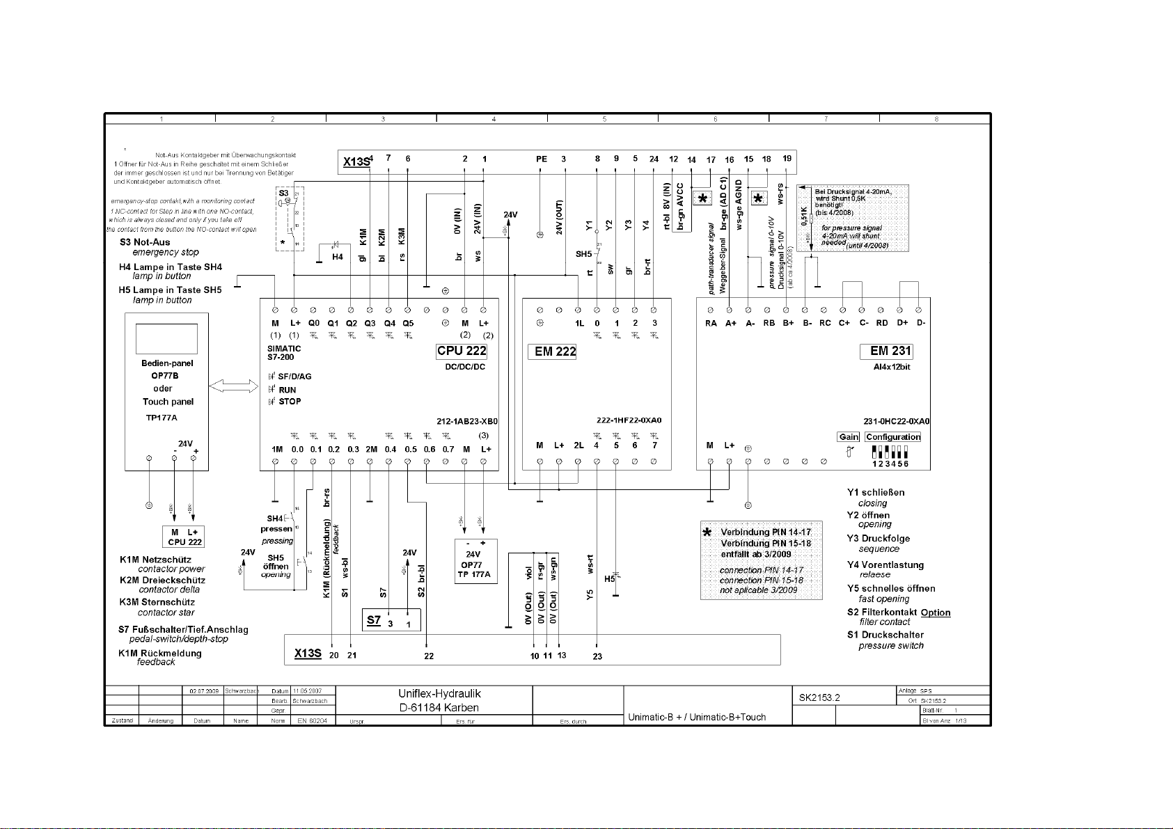
HM 250 / HM 260
Elektroplan / Electric Circuit D iagram (220 /239V 50/60Hz 3Ph)
UNIFLEX-Hydraulik - 37 - www.uniflex.de
Page 38

HM 200 / HM 250 / HM 260
Hydraulikplan / Hydraulic Diagram
UNIFLEX-Hydraulik - 38 - www.uniflex.de
Page 39
HM 200 / HM 250 / HM 260
UNIFLEX-Hydraulik - 39 - www.uniflex.de
Page 40

Wartungsbuch / Maintenance book / Car net d’entretien / Libr o de mantenimiento / Li bretto die manutenzio ne / Onderhoud boek
UNIFLEX-Hydraulik - 40 - www.uniflex.de
Page 41

Erklärung des geschulten Personals / Declaration of Trained Personnel
Ich erkläre hiermit, dass ich an einer innerbetrieblichen Schulung zur Bedienung der UNIFLEX Maschine teilgenommen habe und über alle sicherheitsrelevanten Details
informiert wurde. Des Weiteren erkläre ich, dass ich diese Betriebsanleitung vollständig gelesen und verstanden habe.
I herewith declare that I have attended an internal training course for the operation of this machine and have been informed about all details regarding safety.
I also declare that I have read and understood this operating manual in full.
Par la présente, je déclare avoir suivi une formation dans l’entreprise pour m’initier à l’utilisation de la machine UNIFLEX et avoir été informé de tous les détails liés à la
sécurité. De plus, je déclare avoir lu et compris entièrement la présente notice d’instructions
Confirmo con esto de haber participado en un entrenamiento interno para la operación de la máquina UNIFLEX, y que fue informado sobre todos l os detalles relevantes a
la seguridad técnica. Además, confirmo de haber leido y comprendido el presente manual de instrucciones por completo.
Ort / Place Datum / Date Name / Name Unterschrift / Signature
Lieu / Lugar Date / Fecha Nom / Nombre Signature / Firma
Ort / Place Datum / Date Name / Name Unterschrift / Signature
Lieu / Lugar Date / Fecha Nom / Nombre Signature / Firma
Ort / Place Datum / Date Name / Name Unterschrift / Signature
Lieu / Lugar Date / Fecha Nom / Nombre Signature / Firma
Ort / Place Datum / Date Name / Name Unterschrift / Signature
Lieu / Lugar Date / Fecha Nom / Nombre Signature / Firma
Ort / Place Datum / Date Name / Name Unterschrift / Signature
Lieu / Lugar Date / Fecha Nom / Nombre Signature / Firma
Ort / Place Datum / Date Name / Name Unterschrift / Signature
Lieu / Lugar Date / Fecha Nom / Nombre Signature / Firma
UNIFLEX-Hydraulik - 41 - www.uniflex.de
Page 42

Note :
UNIFLEX-Hydraulik - 42 - www.uniflex.de
Page 43

Note :
UNIFLEX-Hydraulik - 43 - www.uniflex.de
Page 44

Note :
UNIFLEX-Hydraulik - 44 - www.uniflex.de
 Loading...