

Page 1

OPERATING MANUAL
- EM 1
- EM 2
- EM 3.2 Ecoline / EM 3.3 / EM 3.4 DC
Technical Details subject to change EN
Copyi ng and dist ributing this document a nd the use or communicat ion of t he conte nts ther eof are forbidden without e xpressed auth ori ty.
Offenders are li able to the paym ent of dama ges. All rights are rese rved in the even t of the gr ant of a pate nt or the registrat ion of a utility model o r
design.
Page 2

UNIFLEX-Hydraulik - 2 – www.uniflex.de
CE Declaration of Conformity
within the meaning of Directive Machines 2006/42/EEC.
The following machine
EM 1
EM 2
EM 3.2 Ecoline / EM 3.3 / EM 3.4 DC
was developed, designed and manufactured in accordance with Directive 2006/42/EC under the sole responsibility
of
Company UNIFLEX - Hydraulik GmbH
Robert-Bosch-Straße 50 - 52
D - 61184 Karben
Documentation officer Carsten Baumgartner
The following standards, directives and specifications were applied:
• EG-Richtlinie 2006/42/EG - Directive 2006/42/EEC
• EG-Richtlinie 2006/95/EG - Directive 2006/95/EEC
• EMV Richtlinie 2004/108/EG - EMC Directive 2004/108/EEC
• EN ISO 12100: 2010
• EN 60204: 2006
If the machine is changed in any way without consulting us beforehand or if any non-tested and non-accepted
outside parts are used, this declaration shall lose its validity.
Complete technical documentation is available.
The operating instructions supplied with the machine is the original version.
---------------------------------- -------------------------------------- --------------------------------------
Place, Date Signature Function of the signee
Geschäftsführer /
Gérant
Karben, 25. März 2013
Page 3

UNIFLEX-Hydraulik – 3 – www.uniflex.de
Contents
CE Declaration of Conformity .................................................................................................................... 2
Contents ................................................................................................................................................... 3
Chapter 1 Introduction ................................................................................................................. 5
Copyright .................................................................................................................................................................. 5
General information regarding the operating instructions ..................................................................................... 5
Safety and accident prevention ............................................................................................................................. 5
Pictograms ............................................................................................................................................................. 5
Chapter 2 Security and accident prevention ...................................................................................... 6
General Security notes .............................................................................................................................................. 6
The owner undertakes to: ...................................................................................................................................... 6
Obligations of the personnel .................................................................................................................................. 6
Hazards when operating the machine ................................................................................................................... 6
Usage to the intended purpose ............................................................................................................................. 6
Warranty and liability ............................................................................................................................................. 6
Informal safety measures ...................................................................................................................................... 7
Training of the personnel ....................................................................................................................................... 7
Control of the hose cutting and skiving machine ................................................................................................... 7
Safety measures for normal operation .................................................................................................................. 7
Hazards caused by electrical energy .................................................................................................................... 7
Maintenance and servicing, trouble-shooting ........................................................................................................ 7
Constructional modifications of the machine ......................................................................................................... 7
Cleaning the machine and waste disposal ............................................................................................................ 7
Security installations .............................................................................................................................................. 8
Emergency switch ................................................................................................................................................. 8
Security devices .................................................................................................................................................... 8
Test the correct functioning of the knife protection ............................................................................................... 8
Personal safety.......................................................................................................................................................... 8
Chapter 3 System Description ....................................................................................................... 9
Technical Data .......................................................................................................................................................... 9
Design ..................................................................................................................................................................... 10
Chapter 4 Commissioning .......................................................................................................... 11
Unpacking / Set up .............................................................................................................................................. 11
How to prevent damage when unpacking: .......................................................................................................... 11
Connecting the electric supply (Alternating Current) .............................................................................................. 12
Checking the rotating direction of the electric motor (only with 3-Phases) ......................................................... 12
Connecting the electric supply EM 3.4 DC (Continuous Current) ....................................................................... 12
Exhaust ................................................................................................................................................................ 13
Overload protection ............................................................................................................................................. 13
Commissioning the EM 1 ...................................................................................................................................... 13
Commissioning the EM 3.2 Ecoline ..................................................................................................................... 13
Chapter 5 Operating the machine ................................................................................................ 14
Work preparations ................................................................................................................................................... 14
Cutting of Hoses .................................................................................................................................................... 16
Cutting without pneumatic feeder ( EM 1 / EM 2 / EM 3.3 / EM 3.2 Ecoline ) ..................................................... 16
Cutting with EM 3.4 DC ....................................................................................................................................... 16
Brushing ................................................................................................................................................................. 17
Chapter 6 Maintenance .............................................................................................................. 18
Maintenance, Service, Repair .............................................................................................................................. 18
Daily Maintenance: .............................................................................................................................................. 19
Weekly Maintenance: .......................................................................................................................................... 19
Annually Maintenance: ........................................................................................................................................ 19
Disassembling the cutting blade ............................................................................................................................. 20
Assembling the cutting blade .................................................................................................................................. 20
Take off the round brush ......................................................................................................................................... 21
Mounting the round brush ....................................................................................................................................... 21
Change of the driving disk EM 3.4 DC .................................................................................................................... 22
Anhang / Appendix / Apèndice / Appendice ............................................................................................. 23
Ersatzteilliste / Spare Parts List / Pièces détachées / Lista de piezas de recambio ............................................... 23
Page 4

UNIFLEX-Hydraulik – 4 – www.uniflex.de
EM 1 ........................................................................................................................................................................ 23
EM 2 ........................................................................................................................................................................ 24
EM 3.4 DC ............................................................................................................................................................... 25
EM 3.3 ..................................................................................................................................................................... 26
EM 3.2 Ecoline ........................................................................................................................................................ 27
Wo Sie Ersatzteile bestellen können / Where to obtain spare parts / ..................................................................... 30
Adresse pour nous contacter / La dirección para encargar piezas de recambio: ............................................... 30
Elektroplan / Electric Circuit Diagram / Schéma électrique / Esquema de circuitos eléctricos ........................... 31
EM 2 (220 / 230 V, 50 / 60 Hz, 3~) ...................................................................................................................... 31
EM 2 (400 V, 50 / 60 Hz, 3~) ............................................................................................................................... 32
EM 3.4 DC (24V) ................................................................................................................................................. 33
EM 3.4 DC (12VDC / 24VDC) ............................................................................................................................. 34
EM 3.2 Ecoline .................................................................................................................................................... 35
EM 3.3 (220-230 V, 60 Hz, 3~) ............................................................................................................................ 36
EM 3.3 (440-460 V, 60 Hz, 3~ / 380-415 V, 50 Hz, 3~) ...................................................................................... 37
Wartungsbuch / Maintenance book / Carnet d’entretien / Libro de mantenimiento / Libretto die manutenzione /
Onderhoud boek .................................................................................................................................................. 38
Erklärung des geschulten Personals / Declaration of Trained Personnel ........................................................... 39
Gültig seit: 16.07.14
Änderungszustand: y
Erstellt : Jarrasch
Genehmigt:
Page 5

UNIFLEX-Hydraulik – 5 – www.uniflex.de
Chapter 1 Introduction
Copyright
The copyright for this operating manual rests with the company UNIFLEX-Hydraulic GmbH. This operating manual
is meant for the owner / operator of the machine. It contains regulations and notes that may not be copied in part or
as a whole or distributed in any way. Noncompliance may have legal consequences.
General information regarding the operating instructions
This operating manual forms part of the scope of delivery of your UNIFLEX cutting and skiving machine and it is
intended for the user and maintenance / service staff.
The manual describes how the funciton of the machine, provides information on hazards that may arise during its
operation, contains detailed information on how to operate the machine, and describes the steps necessary for
servicing and checking the accuracy of the cutting and skiving machine. Even if you have attended a training
course for operating this machine, please read these operating instructions completely before starting up the
machine.
By signing your name on the last page >Appendix<, you confirm that you have read completely and understood
this Operating Manual. The owner of the machine shall be obliged to only let such persons operate and carry out
maintenance work on the cutting and skiving machine, who satisfy the above-mentioned prerequisite.
Safety and accident prevention
This cutting and skiving machine is a state-of-the-art machine and it is safe to use. Nonetheless, certain rules have
to be observed to minimize the risk of injuries and protect the machine.
Please pay particular attention to Chapter 2 >Safety< in these operating instructions.
Pictograms
This pictogram indicates texts providing useful information on the application of the machine and how it
can be handled and used optimally.
This symbol points out critical points, which can lead to damage of the machine, incorrect functioning, or
faulty production.
This symbol points out hazards to life and health as well as risks of injuries.
This symbol refers to hazards arising during the work process.
Page 6

UNIFLEX-Hydraulik – 6 – www.uniflex.de
Chapter 2 Security and accident prevention
Warning:
Serious accidents may occur, if the machine is handled incorrect.
The cutting and brushing machine is built with up-to-date technology and is functioning safely when operated
correctly. However, there are some regulations which limit the risk of damages for the operator, third persons or the
machine.
General Security notes
These operating instructions contain the most important information needed to operate the cutting and brushing
machine safely. These instructions, particularly the safety information, have to be observed by all persons
operating the machine. Furthermore, all rules and regulations regarding the prevention of accidents, which are
applicable at the place of use, have to be observed.
The owner undertakes to:
• only let such persons work at the machine who are familiar with the basic regulations on work safety and
accident prevention,
• have been instructed in the operation of the UNIFLEX machine, and
• have read and understood the operating instructions and have confirmed this with their signature on the last
page.
The owner shall check at regular intervals whether the personnel is operating the machine according to the safety
regulations.
Obligations of the personnel
All persons authorized to work at this Uniflex cutting and brushing machine are obliged to observe the basic
regulations on work safety and accident prevention, to read the operating instructions and to confirm with their
signature on the last page that they have understood the instructions.
Hazards when operating the machine
This machine has been constructed according to state-of-the-art engineering and acknowledged safety regulations.
Nonetheless, dangers can arise for the operator or third persons, or the machine and/or other property can be
damaged during operation of the machine. The machine may only be used:
• for its proper purpose and intended use,
• when it is in perfect and safe working order.
• Any faults have to be remedied immediately.
Usage to the intended purpose
This UNIFLEX machine is designed only for cutting and brushing hydraulic hoses. Any other usage or any usage
exceeding the tasks described above shall not be considered usage to the intended purpose. Operating the
machine in a potentially explosive atmosphere is prohibited.
Usage to the intended purpose also includes the following:
• observance of all information and instructions provided in the operating instructions and
• observance of the inspection and maintenance work.
Other types of application shall only be permissible following prior consultation with the manufacturer!
Warranty and liability
As a rule our "General Terms and Conditions of Sale and Delivery" shall apply. These will have been made
available to the buyer at the latest when the purchase agreement was concluded. Warranty and liability claims for
injuries to persons and/or damage to property shall be excluded if such claims can be attributed to one or several
of the causes listed below:
• Improper use of the machine, i.e. not to the intended purpose.
• Improper assembly, start up, operation and/or maintenance/repair of the machine.
• Operation of the machine without the protective coverings being mounted correctly.
• Non-observance of the information concerning the transport, storage, assembly, start up, operation and
maintenance of the machine provided in the operating manual.
• Unauthorized constructional changes on the machine.
• Unauthorized modification of programs that affect the control of the machine.
• Inadequate inspection of wearing parts.
• Incorrectly performed repair work.
• Emergencies due to external causes and/or force majeure.
Page 7

UNIFLEX-Hydraulik – 7 – www.uniflex.de
We grant a warranty of 12 months on our machines, valid from the passing of liability. A condition for this is that
enclosed UNIFLEX-accessories or by UNIFLEX tested and approved material is being used and the operation is
done in accordance to this manual.
Informal safety measures
The instruction manual is to be kept together with the machine at all times. General as well as local regulations for
accident prevention and environmental protection are to be displayed and adhered to in addition to the instruction
manual. All security and danger notes on the machine are to be kept in a readable condition.
Training of the personnel
Only adequately trained and instructed personnel should be authorized to work at the machine. The responsibilities
of the personnel as to the assembly, start up, operation, maintenance and repair of the machine should be clearly
defined. Personnel undergoing training should only work at the machine under the supervision of an experienced
person.
Control of the hose cutting and skiving machine
Under no circumstances may the control system be modified in any way!
Safety measures for normal operation
The machine must only be operated when all protective coverings have been mounted correctly. Prior to switching
on the machine it must be certain that no-one can be injured or endangered by the starting machine. Inspect the
outside of the machine at least once during every shift to check for any damages. After finishing working with the
machine switch it off on the main switch.
Hazards caused by electrical energy
Only qualified electricians should carry out work on the electric power supply. The electrical components of the
machine need to be checked at regular intervals. Any loose connections and damaged cables should be repaired
immediately. The housing must always be kept closed. Access should only be permitted to authorized personnel.
Warning:
If work on live parts of the machine is required, a second individual shall be present to operate the
machine Power switch in case of emergency.
Maintenance and servicing, trouble-shooting
Carry out prescribed maintenance work on time. Inform operating personnel before you begin with the maintenance
and servicing work. Always make sure that the machine is off circuit when any maintenance, inspection or repair
work is to be carried out and that the main switch cannot be switched on unintendedly (i.e. by securing it
accordingly). Put up a warning sign prohibiting any third persons from starting up the machine. Make sure that all
connections are firmly tightened. Mount all protective and safety guards again as soon as the maintenance work
has been completed.
Constructional modifications of the machine
The hose skiving machine may not be modified and no parts may be built on or modified without the manufacturer’s
approval. Any modifications need to be confirmed in writing by UNIFLEX-Hydraulik GmbH. Any parts that are not in
perfect working order should be replaced immediately. Only original spare parts and wearing parts should be used.
It cannot be guaranteed that other parts are designed and manufactured in such a way that they will meet the
safety requirements.
Cleaning the machine and waste disposal
All substances and materials used have to be handled and disposed of properly, in particular when work with
lubricants was carried out.
The national regulations on waste disposal have to be observed.
Page 8

UNIFLEX-Hydraulik – 8 – www.uniflex.de
Security installations
The main switch is located at the front of the machine on the operating board.
Emergency switch
Note:
The emergency switch must be activated in all situations where injuries of people or damage on the
machine can arise:
When operating this switch, the cutting and brushing devices of the machine stop within 10 seconds.
Security devices
The cutting and brushing machine has a security device, which protects the operator from contact with the cutting
knife:
Test the correct functioning of the knife protection
Once a week test the functioning of the knife protection. See chapter >maintenance< in this operating manual.
Prior to every switching on of the machine all safety devices have to be assembled correctly, they have to function
correctly and they must be closed. They may only be removed by authorized personnel after a complete standstill
and after protecting against a startup of the machine.
When additional parts are supplied at a later date, the owner shall be responsible for mounting any warning labels
and safety devices delivered with such parts on the machine according to regulations.
Personal safety
Irrespective of the local accident prevention regulations, the following instructions should be observed as a means
of protecting the health and safety of the maintenance and operating personnel:
• Never reach into the skiving machine during operation.
• Always keep a copy of the operating instructions at the place of use of the machine.
• Make sure that all safety and danger notices on the machine are always legible.
• Only operate the machine when all safety devices are in perfect working order.
• Before starting up the hydraulic unit, make sure that no-one can be endangered by the running machine.
• Do not place any objects on the floor near the workplace.
• Do not wear loose clothing.
• Remove any jewelry, watches and rings.
• Wear working gloves.
• Wear safety glasses.
• Wear ear protection when cutting with EM 3.4 DC / EM 3.2 Ecoline.
A danger for the health and safety of the operator does not arise during correct use of the machine. However, we
point to the following dangerous areas
Warning:
Never reach into the skiving area when the machine is working!
Warning:
Always wear protecting glasses when brushing a hose!
Warning:
During all maintenance and repair works switch off the machine on the main switch and disconnect it
from the circuit!
Page 9

UNIFLEX-Hydraulik – 9 – www.uniflex.de
Chapter 3 System Description
Technical Data
Technical Data
EM 1
EM 2
EM 3.4 DC
EM 3
.3 EM 3.
2
Ecoline
Workshop
SAE R13 & SAE R15
- 1 ¼“ 1 ¼“ 1 ¼“ 1 ¼“
Production
SAE R13 & SAE R15
- ¾“ ¾“ ¾“ -
SAE R12
5/8“ 1 ¼“ 1 ¼“ 1 ¼“ 1 ¼“
Industrial
1 ¼“ 2“ 2“ 2“ 1 ¼“
Maxi outside
Ø 45 mm Ø 80 mm Ø 80 mm Ø 80 mm Ø 52 mm
Hosefeed Manual Manual Manual Manual Manual
Noise Level
80 dBA 80 dBA 93 dBA 80 dBA 90 dBA
Brake Motor
- YES - YES -
Suction connection
Ø 30 mm Ø 80 mm Ø 40 mm Ø 80 mm Ø 40 mm
Drive 1,2kW 1Ph 3 kW
12 VDC = 2,0 kW
24 VDC = 3,2 kW
3 kW 2,8 kW
Cutting blade (mm)
160x2,5x20 275x3x30 250x2,5x40 275x3x30 200x1,6x25,4
Brushing DN 5-6-8-10-1216-19-25-31-38-51
- YES - - -
L-W-H (mm)
360x340x310 630x440x330 470x567x365 540x440x300 400x510x540
Weight ca.
8 kg 65 kg 25 kg 50 kg 20 kg
Options
Bench
YES YES YES YES YES
Page 10

UNIFLEX-Hydraulik – 10 – www.uniflex.de
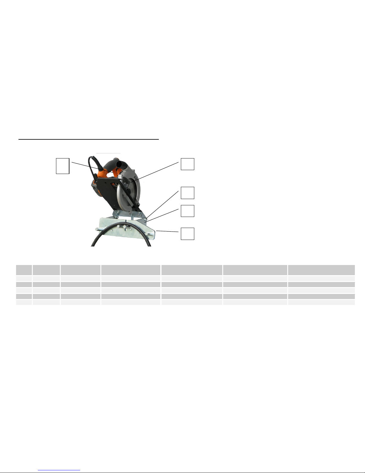
Design
EM 1
EM 2 EM 3.3
EM 3.2 Ecoline
EM 3.4 DC
1 Cover 6 Cutting Support 11 Upper Hexagon Head Bolt
2 Blade Protection 7 Bending Bolt 12 Lower Hexagon Head Bolt
3 Brake Motor 8 Main Switch 13 Electric Motor
4 Pedal Switch 9 Handle
5 Hand Lever 10 Holding Disk
2
9
10
11
12
6
13
2
7
5
6
3
1
13
7
6
5
2
2
5
14
8
9
Page 11

UNIFLEX-Hydraulik – 11 – www.uniflex.de
Chapter 4 Commissioning
Note:
The machine may only be commissioned and operated by trained and authorized personnel!
Unpacking / Set up
The cutting and skiving machine was tested prior to delivery and is ready for operation.
How to prevent damage when unpacking:
• Carefully remove all packaging.
• Check the delivery for completeness using the delivery note.
• Remove all screws that fasten the machine to the packaging.
• Use suitable lifting gear to lift the machine off the palette.
Note:
Pay attention to the correct balance!
Note:
Set the machine in such a way that it is accessible from all sides for maintenance works.
Note:
Only set up and operate the machine in weather proof rooms.
• Lift the machine on the included workbench (optional).
• Fasten the machine to the workbench. (Rubber-metal buffer reduce vibrations).
Note:
The work bench must be level.
The cutting support should go further than the desk so the hose can be guided towards the cutting knife or the
round brush freely (EM 3.4 DC; EM 3.2 Ecoline).
Page 12

UNIFLEX-Hydraulik – 12 – www.uniflex.de
Connecting the electric supply (Alternating Current)
Caution:
This work should only be performed by a qualified electrician! Note the marked voltage on the type plate
and select the appropriate electric circuit diagram! Works on live wires are hazardous!
• Switch the main connection of the machine off-circuit and make sure that it cannot be switched on again.
• Connect the electric connecting cable to the connection of the power supply. For the correct voltage refer to the
type plate.
Note:
The rotating direction of the electric motor is indicated by an arrow on the motor / chassis!
Note:
The connecting plug must comply with current local electrical regulations!
Checking the rotating direction of the electric motor (only with 3-Phases)
If the motor does not rotate in the direction indicated by the arrow, two phases must be switched as
shown:
Attention:
The motor will be damaged if it rotates in the wrong direction for some time.
Connecting the electric supply EM 3.4 DC (Continuous Current)
+ Pol
- Pol
• 12 VDC / 24 VDC Continuous Current, To screw
tightly.
• No Gelbattery.
• Look for an adequacy engine power of the
current generator.
• Suitable fuse: 250 A: 12 VDC inactive
: 150 A: 24 VDC inactive
Page 13

UNIFLEX-Hydraulik – 13 – www.uniflex.de
Exhaust
The exhaust behind the cutting blade and the round brush has to be connected with a metal hose to suck off the
smoke and debris.
We recommend an exhaust fan 100 mm WS and a suction of 4 m 3/min as well as a filter element suited for this
application.
Attention:
Put on the safety goggles before switching on the machine!
Adhere to the safety regulations!
Overload protection
Note:
The Motor is protected by a thermal contact against overloads.
• If necessary leave the motor to cool off and start anew.
• The warm restart protection prevents an unintended start of the machine. Another restart is only possible by
pushing the start key.
Commissioning the EM 1
The UNIFLEX EM 1 has been designed as a table machine and should be mounted to a solid working bench using
two bore holes of Ø 11 mm located in housing bottom. The machine should extend about 30 mm over the table
edge so that hoses to be cut may be jammed between the hexagon bolt.
Make sure that the voltage displayed on the type plate is identical to the voltage that is fed to the machine.
Commissioning the EM 3.2 Ecoline
The UNIFLEX EM 3 Ecoline / EM 3.2 Ecoline has been designed as a table machine and should be used on a solid
work bench. Two bore holes of Ø 9 mm located in the chassis (refer to drawing) should be used in case of a
stationary mounting. Make sure that the voltage displayed on the type plate is identical to the voltage that is fed to
the machine.
Note:
Operation S2 – 5min / Service machine. To protect against overheating the machine may never be used
for more than 5 minutes continuously. After that the switched off motor needs to be left to cool for at
least 10 minutes.
1 Bore holes for
transport and for
table top
operation
3 Left Guide
2 Right Guide 4 Bore holes for
transport
1
2 3
4
Page 14

UNIFLEX-Hydraulik – 14 – www.uniflex.de
Chapter 5 Operating the machine
Work preparations
Note:
Choose the correct distance between the holding pins /guides. Note Pictures A, B and C!
Generally it can be said for the distance between the holding pins:
Large hose diameter
= large distance ! (see Picture A)
Small hose diameter
= small distance ! (see Picture B)
Never cut without bending (see Picture C)
Holding pins / Guides
Picture A
z.B DN 38
Holding pins / Guides
Picture B
z.B DN 16
Picture C
Attention:
Never cut without bending.
Attention:
The hoselength must be minimum outside of the Bending Bolt (Guides).
Page 15

UNIFLEX-Hydraulik – 15 – www.uniflex.de
Note:
The safe and professional cutting is only possible with correctly set holding pins / guides. (see position
of holding pins in pictures A and B on page 15).
Attention:
The cutting without pretensioning the hose is dangerous and therefore forbidden! (See picture C, page 15)
During the cutting process the hydraulic hose needs to open so that no lateral friction arises and the cutting blade
cannot heat up. The feeding speed has to be adapted to the material thickness.
• Hose assemblies should be guided smoothly to the rotating cutting blade.
• They should be cut evenly as well as quickly.
Note:
When cutting extremely heavy hoses, the cutting pressure should be lowered.
Hand lever or foot pedal should be opened shortly to continue cutting slowly.
With pneumatic machines control the air pressure according to hose thickness.
Attention:
When cutting inappropriately the cutting blade can anneal and break
Note:
Cracked or deformed cutting blades need to be exchanged immediately.
Page 16

UNIFLEX-Hydraulik – 16 – www.uniflex.de
Cutting of Hoses
The blade protection opens and closes automatically with each cutting process.
Warning:
Never operate the blade protection by hand!
Cutting without pneumatic feeder ( EM 1 / EM 2 / EM 3.3 / EM 3.2 Ecoline )
• Prepare the machine as shown above.
• Mark the desired cutting length.
• Start the machine by turning the main switch to «I».
• Place the hose line in front of the holding pins on the cutting support.
• Hold the hose ends, tense with the hand lever and at the same time pull / push the hose assembly through.
• After cutting the hose line, put the hand lever back to its original position.
• Take out hose pieces.
• By turning the main switch to position «O» switch the machine off.
Cutting with EM 3.4 DC
• Wear ear protection.
• Cut as shown <cutting without pneumatic feeder>.
• Don´t operating with gel batteries
• Make sure the Batteries are protected for overloading.
• Use sufficient dimensioned Batteries
• Don´t cut several hose line one after another.
Page 17

UNIFLEX-Hydraulik – 17 – www.uniflex.de
Brushing
• Prepare the machine as detailed above.
• Insert the skiving mandrel in clamping device A and secure with clamping decive B.
• The skiving length is set by the positioning of the skiving mandrel (+ or –).
• Place the hose end on the skiving mandrel and hold while you use setting screw E to move the hose against
the round brush. Do this until the desired skiving depth has been reached.
• Fasten the clamping screw F. Then start the motor using the main switch (Position «I»).
• Use both hands to turn the hose over the skiving mandrel. When the skiving process is finished, carefully
remove the hose.
• Turn the machine off by operating the OFF-Switch «O».
EM 2
A
E F
B
Page 18

UNIFLEX-Hydraulik – 18 – www.uniflex.de
Chapter 6 Maintenance
Maintenance, Service, Repair
All maintenance and repair works may only be performed by authorized and trained personnel.
• Stick to the specified maintenance and inspection periods.
• Inform the operating personnel prior to conducting all special works on the machine.
• Identify a supervisor prior to this work.
• For all works that modify the operation, the settings according to products, general modification of the setting of
the machine and its security relevant devices adhere to the correct activation / deactivation procedures
mentioned in this document. If necessary secure the area.
• If the machine is turned off completely for maintenance or repair works, ensure against unintended switching
on: Set up a warning sign.
• Clean the machine and all (screwed) connections off oil, fuel or cleaning agents! Do not use any aggressive
cleaning agents! Use fibreless cleaning cloths!
• After the cleaning check all fuel-, motor oil- and hydraulic oil connections for leakage, loose connections,
abrasion and other damages. Remove these faults immediately!
• If a disassembling of protecting devices becomes necessary during the general assembling, maintenance- or
repair works of the machine, a remounting after finishing the works has to follow immediately.
• Always refasten the screws that were loosened during maintenance and repair.
• If the disassembling of any safety installations becomes necessary during maintenance, service or repair it
needs to be replaced and checked directly after finishing the works.
• Make sure to discard all operating and auxiliary materials safely and environmentally friendly.
• Only conduct welding, firing or grinding on the machine if it is explicitly allowed, as there may be the danger of
fire or explosion!
• Prior to any welding, firing or grinding clean the machine and the surroundings of dust and flammable
substances and provide adequate ventilation (Danger of explosion)!
Attention:
Do not remove safety installations!
Attention:
Check the functioning of the emergency stop button regularly!
Attention:
The machine needs to be switched off on the main switch during all maintenance works!
Page 19

UNIFLEX-Hydraulik – 19 – www.uniflex.de
Daily Maintenance:
• Required are a rag and some detergent.
• Clean the machine from any cutting / skiving residue
• Check the form of the cutting blade and check it for fissures.
• Check the housing and cable for defects.
• Pay attention to any unusual noises and vibrations
• Keep the machine dry.
• Use a vacuum cleaner or another suitable object to remove any dirt particles.
Weekly Maintenance:
• If necessary sharpen or exchange the blade.
• Check the security settings of the blade protection: Turn the machine off. With a chain-glove push the
protection towards the cutting blade.
Attention:
The protection may only yield to a considerable force. The movement of the protection should be
constant at all times, otherwise you need to check the spring mechanism of the protection.
Annually Maintenance:
• Check the security settings and functioning elements of the machine.
• Clean the machine and if required the attached suction line.
Page 20

UNIFLEX-Hydraulik – 20 – www.uniflex.de
Disassembling the cutting blade
Loosen all screws of the cover and pull the same of.
At all machine with pneumatic feed, disconnect the compressed air up to the service unit.
Warning:
The cutting blade is extremely sharp! Always wear special gloves when working on the cutting
blade!
1. Block the dri ve shaft to prevent rotatio n:
EM 3. 4 D C
EM 2
Pull the hand le ver as f ar as possi ble t owa rds you.
Push a Ø 6 mm mandrel th rough th e bore hole.
Secur e t he drive shaft w ith a combination wrench between motor a nd
brush.
EM 3. 2 E colin e
EM 3. 3
Secur e t he drive shaft w ith a ri ng wrench o r a flat wrench SW22 and
loosen t he screw wi th a ring wrench or a ra tch SW13.
Hold the nut wit h a hex key and loosen t he nut with a size 30 ke y.
2. Loose n the ho ldi ng nu t with a combinatio n wrench in the same rot ating di rec tion of the blade.
3Take of f the fl ange disk.
4. We ari ng speci al glove s, caref ully tak e off th e c utting b lade.
Assembling the cutting blade
The assembly of the cutting blade is done in reverse order.
Warning:
Make sure that motor and blade rotate in the same direction, otherwise there ist he danger of damaging
the blade during cutting.
Page 21

UNIFLEX-Hydraulik – 21 – www.uniflex.de
Take off the round brush
Loosen all screws on the cover and pull the same off.
Secure the drive shaft against rotating. (The rotating direction of the nut equals to the rotating direction of the round
brush).
Take nut and flange off and remove the round brush.
Mounting the round brush
To mount the round brush, do the same as is described above in reverse order.
Page 22

UNIFLEX-Hydraulik – 22 – www.uniflex.de
Change of the driving disk EM 3.4 DC
Sequence:
Unscrew the engine screws (2x).
Take off the engine.
Exchange the disk.
Position the engine.
Take care that the engine sprocket meshes with the driving disk.
Remount and tighten the engine screws.
If distance plates had been fitted between the engine and
the chassis, they must be inserted at the same position.
Page 23
UNIFLEX-Hydraulik – 23 – www.uniflex.de
Anhang / Appendix / Apèndice / Appendice
Ersatzteilliste / Spare Parts List / Pièces détachées / Lista de piezas de recambio
EM 1
Pos. Anzahl/
Amount
Artikel / Article
Deutsch
English
Français
Espa
nol
1 1 303.020 Kreissäge Circular saw Scie circulaire Sierra circular
2 1 TM 160 x 2,5 x 20 Trennmesser Cutting blade Lame de coupe Cuchilla de corte
3 1 303.103.3 Gelenk Joint Pièce d’articulation Articulación
4 1 303.101.3 Chassis Chassis Châssis Armazón
5 1 303.102.3 Schneidplatte Cutting Support Support de coupe Placa de corte
1
2
3
4
5
Page 24

UNIFLEX-Hydraulik – 24 – www.uniflex.de
EM 2
E-
Motor / Moteur électrique / Motor
eléctrico
Artikelnr. / Article No.
/ Référence / Article
No.
Spannung / Voltage /
Tension / Voltaje
300.022 230V- 400V, 50Hz, 3~
300.028 415V, 50Hz, 3~
300.029 440V, 60Hz, 3~
300.024 230V, 60Hz, 1~
300.026 230V, 50Hz, 1~
300.027 200V, 50Hz, 3~
304.025 500V, 50Hz, 3~
Pos. Anzahl /
Amount
Artikel / Article
Deutsch
English
Français
Espanol
1 1 302.003.1 Verkleidung links Cover left Capot côté gauche Tapa izquierda
2 1 300.90 Bürstdorne Brushing Mandrels Mandrins de brosse Mandriles cepilladores
3 1 RB 300-200-24 Rundbürste Round Brush Brosse circulaire Cepillo circular
4 1 300.005.1 Stellspindel Adjusting Spindle Broche de réglage Husillo de ajuste
5 1 300.009 / U.300.010 Klemmhebel Clamping lever Levier de blocage Palanca de bloqueo
6 1 300.001.0 Chassis Chassis Châssis Armazón
7 1 See table E-Motor Electric Motor Moteur électrique Motor eléctrico
8 1 300.2001 Handhebel Hand lever Levier Palanca manual
9 1 301.002.1 Verkleidung rechts Cover right Capot côté droit Tapa derecha
Ohne Bild /
Pas d´ image
1 TM 300-275x3x30 Trennmesser Cutting Blade Lame de coupe Cuchilla de corte
10 1 301.109.4 Messerschutz Blade Protection Protection de la lame Protector de cuchilla
11 1 300.004.1 Schneidauflage Cutting Support Support de coupe Placa de corte
12 2 304.2001 Biegebolzen Bending Bolt Pige de cintrage Perno de flexión
13 4 300.001 Gummimetallpuffer Rubber-Metal-Buffer Tampon caoutchouc
métal
Cojín metal-caucho
14 1 300.088 Hauptschalter Main Switch Interrupteur principal Interruptor principal
Ohne Bild /
Pas d´ image
1 300.017 Flanschscheibensatz Flange disc set Flasque set
14
7
8
1
4
10
11
12
3
9
5 6
2
13
Page 25
UNIFLEX-Hydraulik – 25 – www.uniflex.de
EM 3.4 DC
Pos. Anzahl /
Amount
Artikel / Article
Deutsch
English
Français
Espanol
1 1 EM 3 DC Maschine komplett Complete machine Machine complète Máquina completa
2 1 TMZ 250x2x40 Z Trennmesser Cutting Blade Lame de coupe Cuchilla de corte
3 1 888.091 Drucktaster Pushbottom Bouton-poussoir Pulsador
4 2 311.008.4 Bolzen Bolt Boulon Bulón
5a
5b
1
1
311.011
311.111
Starter-Motor 12V / 2,0 kW
Starter-Motor 24V / 3,2 kW
E-Motor 12V / 2,0 kW
E-Motor 24V / 3,2 kW
Moteur électrique 12V / 2,0 kW
Moteur électrique 24V / 3,2 kW
Motor eléctrico 12V / 2,0 kW
Motor eléctrico 24V / 3,2 kW
Ohne Bild /
Pas d´ image
2 6006 2RSH Kugellager Bearing Roulement à billes Rodamiento
7a
7b
1
1
311.015.4
311.056.4
Mitnehmerscheibe 12 VDC
Mitnehmerscheibe 24 VDC
Carrier Panel 12 VDC
Carrier Panel 24 VDC
Douille dáccouplement disque
12 VDC
Douille dáccouplement disque
24 VDC
Plato de arrastre 12 VDC
Plato de arrastre 24 VDC
Zubehör
Ohne Bild /
accessoires
Pas d´ image
1 GK 205 A Gleichstrom-Kabelset Direct Current Cable Set Courant continu câble kit Corriente continua cable
juego
9
1 800.014 Sicherungshalter Fuse Holder Porte fusible Detentor de fusible
10
1 800.099 Sicherungseinsatz Fuse Cartridge Cartouche fusible Tapón de fusible
Ohne Bild /
Pas d´ image
1 311.059 Motor Start-Kabel EM3.3DC Motor start cable EM3.3DC Câble starter EM3.3DC Cable de arranque EM3.3DC
12 1 311.027 Zugfeder Extension spring Ressort de traction Resorte regulator
12
1
2 4 5
3
7
9 10
Page 26

UNIFLEX-Hydraulik – 26 – www.uniflex.de
EM 3.3
a.A. / o.r.= auf Anfrage, Angabe Maschinentyp, Baujahr, Seriennummer notwendig /
on request, Machine type, year of construction, serial number must be known /
sur demande, il est indispensable d’indiquer le type, l’année de construction et le numéro de série de la
machine /
En caso de consulta, es preciso saber el tipo, año de construcción y núm. de serie de la máquina
EM 3.3 -
E-Motor
Pos. 2
Artikelnr. /
Article No. /
Référence Nº/
Nº artículo
Schalter / Switch
Pos 8 /
Interrupteur /
Interruptor Pos 8
Bremse /
brake / frein /
freno
Spannung / Voltage/
Tension / Voltaje
300.022 300.088 a.A. / o.r. 230V-400V, 50Hz, 3~
300.050 8.13.005 300.044 230V-400V, 50-60Hz, 3~
300.028 a.A. / o.r. a.A. / o.r. 415V, 50Hz, 3~
300.029 a.A. / o.r. a.A. / o.r. 440V, 60Hz, 3~
300.024 a.A. / o.r. a.A. / o.r. 230V, 60Hz, 1~
300.026 a.A. / o.r. a.A. / o.r. 230V, 50Hz, 1~
300.027 a.A. / o.r. a.A. / o.r. 200V, 50Hz, 3~
300.025 a.A. / o.r. a.A. / o.r. 500V, 50Hz, 3~
300.032 a.A. / o.r. a.A. / o.r. 380V, 60Hz, 3~
Pos. Anzahl
/
Amount
Artikel / Article
Deutsch
English
Français
Espanol
1 1 301.018.0 Chassis Chassis Châssis Armazón
2 1 See table E-Motor Electric Motor Moteur électrique Motor eléctrico
3 1 300.2001 Handhebel Hand lever Levier Palanca manual
4 1 301.002.1 Verkleidung rechts Cover right Capot côté droit Tapa derecha
Ohne Bild /
Pas d´ image
1 TMG 275x3x30 Trennmesser Cutting Blade Lame de coupe Cuchilla de corte
6 1 301.109.4 Messerschutz Blade Protection Protection de la lame Protector de cuchilla
7 2 304.2001 Biegebolzen Bending Bolt Pige de cintrage Perno de flexión
8 1 See table Schalter Switch Interrupteur Interruptor
Ohne Bild /
Pas d´ image
1 300.017 Flanschscheibensatz Flange disc set Flasque set Juego de discos de brida
3
6
7
4
1
2
8
Page 27

UNIFLEX-Hydraulik – 27 – www.uniflex.de
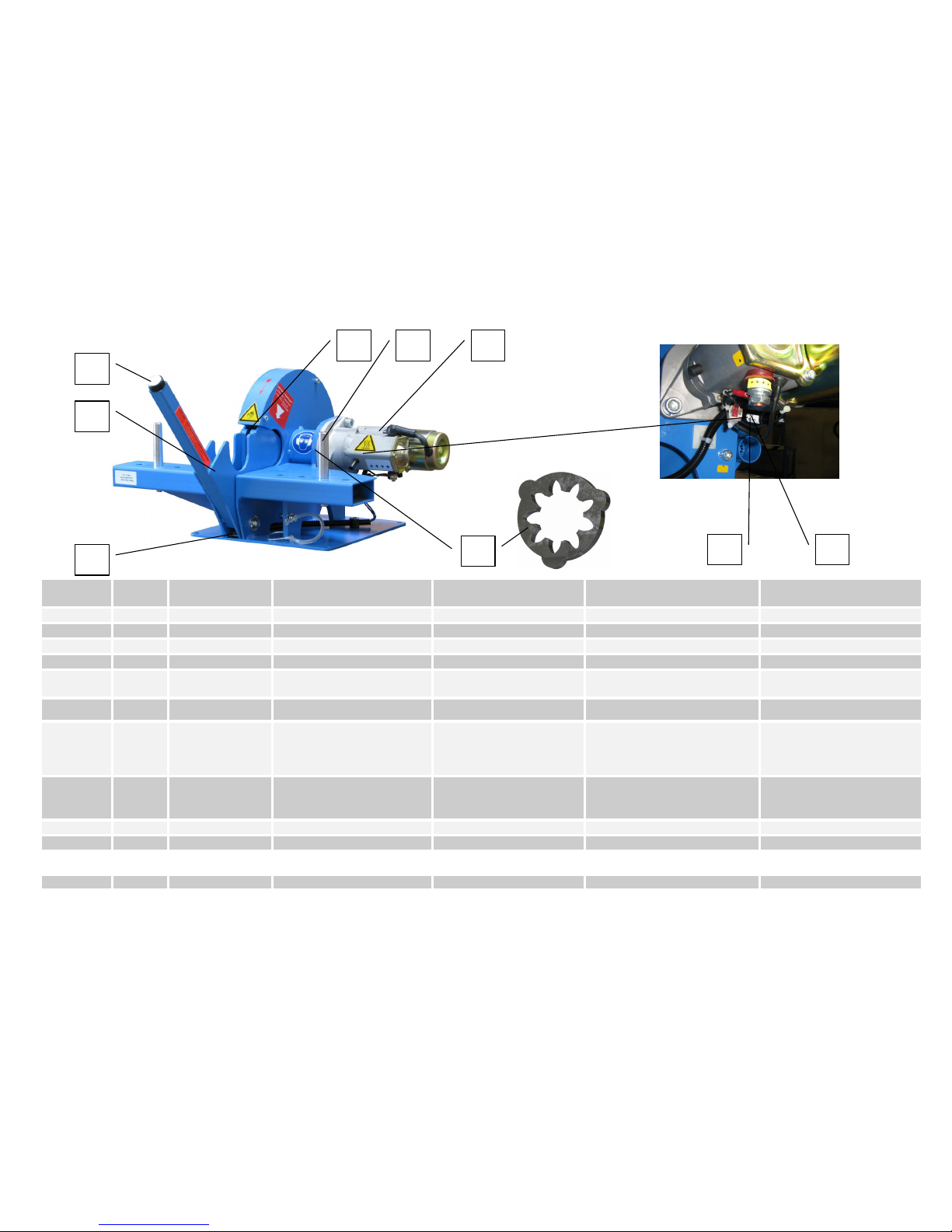
EM 3.2 Ecoline
20 4
2
20
19
4
16
2
5
19
23 17
20
18
6
3
15
31
12
11
8
1
13
33
14
7
34
9
10
32
19
22
27
Page 28

UNIFLEX-Hydraulik – 28 – www.uniflex.de
Pos. Anzahl/
Amount
Artikel / Article
Deutsch
Eng
lish Français
Espanol
1 1 319.200.1 Chassis Chassis Châssis Armazón
2 1 319.201.2 Motorhalterung Motor Fastener Fixation moteur Soporte de motor
3 1 319.202.2 Abdeckhaube Cover Capot moteur Cubierta
4 1 319.106.3 Bedienhebel Lever Levier Palanca de mando
5 2 319.107.4 Zugblech Pulling Plate Pièce de liaison Placa de tracción
6 1 319.203.1 Schutzblech Safety Cover Capot de protection de
lame
Chapa protectora
7 1 319.109.3 Abdeckblech Covering Plate Plaque de protection Chapa salvamanos
8 1 319.205.2 Führungsschiene Guide track Rail de guidage Guía
9 1 319.206.2 Schlitten Slide Coulisseau Carro
10 1 319.207.2 Schwingschutz Swing Protection Volet de protection Protección oscilante
11 1 319.208.4 Gewindestift Set Screw Tige filetée Tornillo de sujeción
12 1 319.209.3 Führung links Guide left Guide côté gauche Guía izquierda
13 1 319.118.3 Führung rechts Guide right Guide côté droit Guía derecha
Ohne Bild /
Pas d´ image
1 319.211.2 Distanzblech Distance Plate Plaque de distance Chapa distancia
14 1 TM G 200x1.6x25.4 Trennmesser Cutting Blade Lame de coupe Cuchilla de corte
15 1 SK 575.4 UNIFLEX-Zeichen, klein UNIFLEX Logo, small Logo UNIFLEX, petit UNIFLEX Logotipo, peque.
16 1 213.090.4 Typenschild Type plate Plaque signalétique Placa de características
17 4 233.111 Gummimetall-Puffer Buffer Tampon caoutchouc
métal
Cojín metal-caucho
18 1 319.120 Spatengriff Handle Poignée du levier Empuñadura
19 8 319.121 Bundbuchse Collar Bush Douille à collet Casquillo con gollete
20 2 319.122 Bügelgriff Handle Poignée en forme d’étrier Asidero
Ohne Bild /
Pas d´ image
1 3166 Richtungspfeil rot Direction Arrow Red Flèche de direction
rouge
Flecha direccional roja
22 1 319.124 Schenkelfeder Leg Spring Ressort spiralé Resorte espiral
23 2 319.125 Zugfeder Pulling Spring Ressort de traction Muelle de tracción
Ohne Bild /
Pas d´ image
1 304.101.4 Hinweisschild Messer Warning Sign Knife Signal d’avertissement Señal de aviso: Cuchilla
25 1 3127/60 Augen- und Gehörschutz
tragen
Warning Sign Wear Eye
and Ear protection
Signal d’avertissement
du port de lunettes de
sécurité et d’un casque
anti-bruit
Señal de aviso: Usar
protección ocular y de oído
Ohne Bild /
Pas d´ image
1 716.4 Warnschild Warning Sign Signal d’avertissement Señal de aviso
Page 29

UNIFLEX-Hydraulik – 29 – www.uniflex.de
27 2 501.071 Rastbolzen Locking Pin Boulon d’arrêt Perno de retención
Ohne Bild /
Pas d´ image
1 300.100.4 Warn. Schnittverletzung Warning Cutting Injury Signal d’avertissement
d’un risque de coupure
Aviso: Peligro de lesión
por corte
31 1 319.001 E-Motor, 1,8kW
(230V-50Hz-1~)
E-Motor, 1,8kW
(230V-50Hz-1~)
Moteur électrique, 1,8kW
(230V-50Hz-1~)
Motor eléctrico, 1,8kW
(230V-50Hz-1~)
32 1 319.131 Motorschalter 230V-1Ph Motor Interrupter 230V-1~
with. Socket
Interrupteur moteur
230V-1Ph
Interruptor guardamotor
230V-1~
33 1 Nur mit Motor / only with
Motor
Haltescheibe Holding disc Rondelle de fixation Disco de fijación
34 1 Nur mit Motor / only with
Motor
Flanschscheibe Flange disc Flasque Disco de brida
Page 30

UNIFLEX-Hydraulik – 30 – www.uniflex.de
Wo Sie Ersatzteile bestellen können / Where to obtain spare parts /
Adresse pour nous contacter / La dirección para encargar piezas de recambio:
Uniflex Hydraulik GmbH
Robert-Bosch-Straße 50 - 52
D-61184 Karben
Tel.: 06039 / 91 71 – 0
Fax: 06039 / 9171 - 181
E-mail: sales@uniflex.de
http://www.uniflex.de
Bei der Bestellung eines Ersatzteiles bitte unbedingt folgende Angaben machen!
When ordering spare parts please have the following information ready!
Veuillez indiquer impérativement les données suivantes dans votre commande !
¡En el pedido de una pieza de recambio es imprescindible de hacer los siguientes indicaciones!
• Maschinentyp / Machine type / Le type de la machine / Tipo de máquina
• Seriennummer / Serial-Number / Le numéro de série / Número de serie
• Baujahr / Year of production / L’année de construction / Año de construcción
• Spannung / Voltage / La tension de service / Voltaje
Page 31

UNIFLEX-Hydraulik – 31 – www.uniflex.de
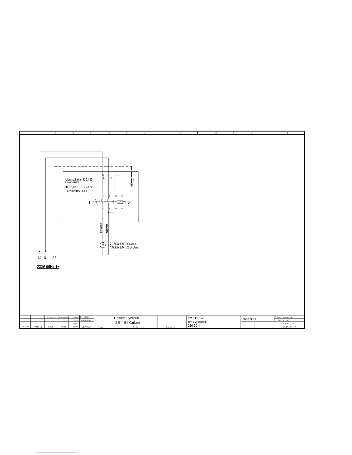
Elektroplan / Electric Circuit Diagram / Schéma électrique / Esquema de circuitos eléctricos
EM 2 (220 / 230 V, 50 / 60 Hz, 3~)
Page 32

UNIFLEX-Hydraulik – 32 – www.uniflex.de
EM 2 (400 V, 50 / 60 Hz, 3~)
Page 33

UNIFLEX-Hydraulik – 33 – www.uniflex.de
EM 3.4 DC (24V)
Page 34

UNIFLEX-Hydraulik – 34 – www.uniflex.de
EM 3.4 DC (12VDC / 24VDC)
Page 35
UNIFLEX-Hydraulik – 35 – www.uniflex.de
EM 3.2 Ecoline
Page 36

UNIFLEX-Hydraulik – 36 – www.uniflex.de
EM 3.3 (220-230 V, 60 Hz, 3~)
Page 37

UNIFLEX-Hydraulik – 37 – www.uniflex.de
EM 3.3 (440-460 V, 60 Hz, 3~ / 380-415 V, 50 Hz, 3~)
Page 38

UNIFLEX-Hydraulik – 38 – www.uniflex.de
Wartungsbuch / Maintenance book / Carnet d’entretien / Libro de mantenimiento / Libretto die manutenzione / Onderhoud boek
Page 39

UNIFLEX-Hydraulik – 39 – www.uniflex.de
Erklärung des geschulten Personals / Declaration of Trained Personnel
Ich erkläre hiermit, dass ich an einer innerbetrieblichen Schulung zur Bedienung der UNIFLEX Maschine teilgenommen habe und über alle sicherheitsrelevanten Details
informiert wurde. Des Weiteren erkläre ich, dass ich diese Betriebsanleitung vollständig gelesen und verstanden habe.
I herewith declare that I have attended an internal training course for the operation of this machine and have been informed about all details regarding safety.
I also declare that I have read and understood this operating manual in full.
Par la présente, je déclare avoir suivi une formation dans l’entreprise pour m’initier à l’utilisation de la machine UNIFLEX et avoir été informé de tous les détails liés à la
sécurité. De plus, je déclare avoir lu et compris entièrement la présente notice d’instructions
Confirmo con esto de haber participado en un entrenamiento interno para la operación de la máquina UNIFLEX, y que fue informado sobre todos los detalles relevantes a
la seguridad técnica. Además, confirmo de haber leido y comprendido el presente manual de instrucciones por completo.
Ort / Place Datum / Date Name / Name Unterschrift / Signature
Lieu / Lugar Date / Fecha Nom / Nombre Signature / Firma
Ort / Place Datum / Date Name / Name Unterschrift / Signature
Lieu / Lugar Date / Fecha Nom / Nombre Signature / Firma
Ort / Place Datum / Date Name / Name Unterschrift / Signature
Lieu / Lugar Date / Fecha Nom / Nombre Signature / Firma
Ort / Place Datum / Date Name / Name Unterschrift / Signature
Lieu / Lugar Date / Fecha Nom / Nombre Signature / Firma
Ort / Place Datum / Date Name / Name Unterschrift / Signature
Lieu / Lugar Date / Fecha Nom / Nombre Signature / Firma
Ort / Place Datum / Date Name / Name Unterschrift / Signature
Lieu / Lugar Date / Fecha Nom / Nombre Signature / Firma
Page 40

UNIFLEX-Hydraulik – 40 – www.uniflex.de
Note:
 Loading...