

Page 1

TEMPORARY
FRONT COVER
West Marine
VHF 150
Page 2

Table of Contents
Quick Start Guide .......................................................................4
Maritime Radio Services Operation ............................................6
FCC/Industry Canada Information ..............................................2
FCC RF Exposure Information ...................................................6
Lithium Ion Battery Pack Warning ..............................................7
Introduction .................................................................................8
Features .....................................................................................8
VHF 150 Controls .....................................................................10
LCD Display..............................................................................13
Owner Manual Conventions .....................................................14
Indicator Sounds.......................................................................14
Batteries ...................................................................................15
Installing the Lithium Ion Battery Pack ...............................15
Using the Alkaline Battery Pack .........................................15
Mounting the Charging Cradle..................................................17
To Mount the Cradle on a Counter Top ..............................17
Mounting on a Wall .............................................................17
Attaching the Belt Clip ..............................................................18
Operation — Getting Started ....................................................19
Operation – Setting the Radio Options .....................................19
USA/CAN/INT — UIC Settings .................................................19
Lamp (Backlight) Adjust ............................................................20
Adjusting Display Contrast .......................................................20
Setting Dual or Tri Watch ..........................................................20
Setting the Key Beep ................................................................21
PAGE NUMBERS
NOT FINAL
2
West Marine VHF150 Radio Owner’s Manual
Page 3

Setting the Key Lock.................................................................21
Using the Weather Channels ....................................................22
Manually Selecting Emergency Channels ................................23
Storing a Channel in Memory ...................................................23
Adding FIPS Codes ..................................................................24
Changing Channel Names .......................................................25
Restoring Default Names .........................................................26
Operation – Selecting a Channel..............................................26
Operation – Transmitting Power Level .....................................26
Operation – Transmitting ..........................................................27
Using the Triple Watch or Dual Watch Mode ............................28
Using Scan with Triple Watch,Dual Watch, or Weather Alert ...29
Triple Watch and Dual Watch Only ....................................29
Weather Channel Only ......................................................30
Both Watches and Weather Channel .................................30
Troubleshooting ........................................................................31
Specifi cations ...........................................................................33
Care and Maintenance .............................................................34
USA Channel Frequencies .......................................................34
Canadian Channel Frequencies ...............................................35
International Channel Frequencies...........................................37
NOAA Weather Channels and Frequencies .............................40
Three Year West Marine Warranty ...........................................42
3West Marine VHF150 Radio Owner’s Manual
Page 4
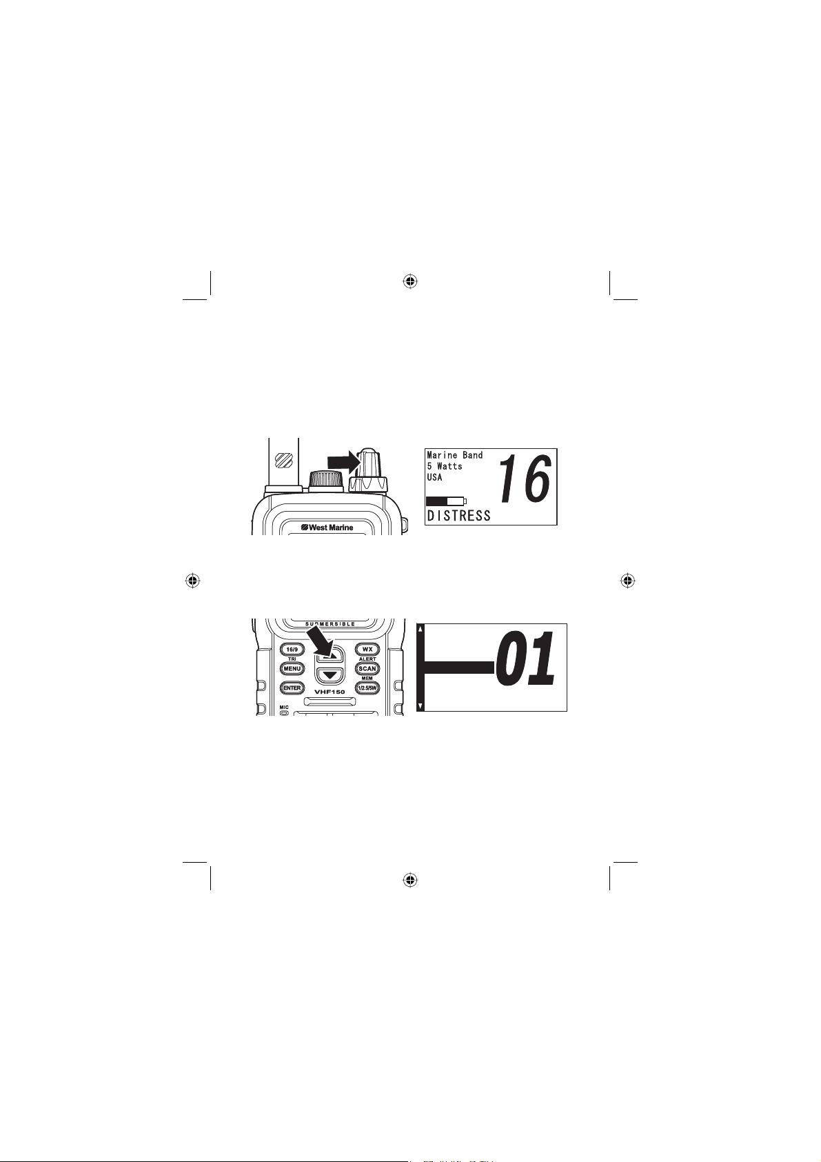
A Quick Start Guide for the VHF150
[
[
R
R
[
[
[
R
R
[
Follow these steps to get going!
1.
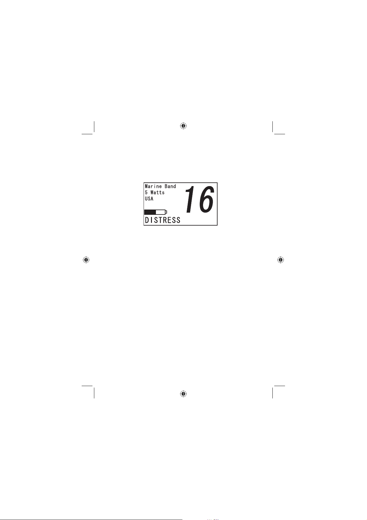
Rotate VOLUME until the display lights. The Power
On tone sounds. The default display shows channel
16 in the US marine band, a 5 watt level and the label
DISTRESS at the bottom edge.
Press Ÿ or ź to change channels. The marine
2.
channels begin at 01 and continue, in a closed loop,
through 88A.
5CHGV
5CHGV
#865%QO
#865%QO
#%)1PN
#%)1PN
#865%QO
#865%QO
#%QOOGTE
#%QOOGTE
/CTQ
/CTQ
/CT1
/CT1
T
T
T
T
/GOQT
/GOQT
#
#
4
West Marine VHF150 Radio Owner’s Manual
Page 5
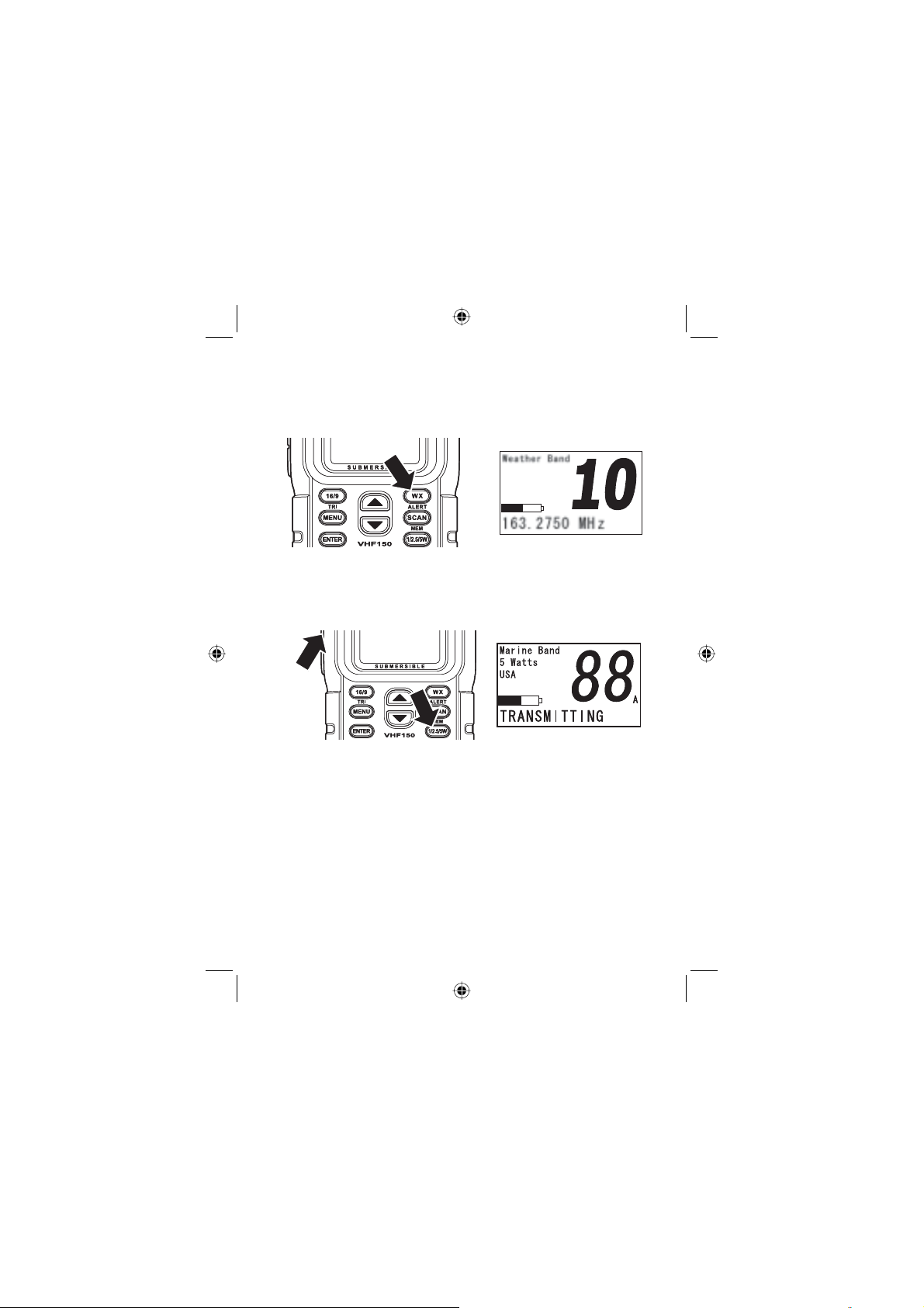
3.
To listen to your local NOAA weather channel, press
WX/ALERT. One channel of the 10 available will be
best. Press WX/ALERT to return to marine channels
1 to 88.
To transmit, repeated press 1/2.5/5W to select a pow-
4.
er level. Then, press Ÿ or ź to select a channel.
Press PTT. The display confi rms transmitting at the
5.
bottom of the screen and your power level as well.
To learn about other sections which contain details dealing
with General Setup, Battery Operation and Charging, Menu
Options, Storing Channels, Scanning Channels, and using
the special features of either Triple or DualWatch, consult
the Table of Contents which immediately preceeds these
Quick Start pages.
5West Marine VHF150 Radio Owner’s Manual
Page 6

Maritime Radio Services Operation
Warning! This transmitter will operate on channels/frequen-
cie that have restricted use in the United States. The channel
assignments include frequencies assigned for exclusive use
of the U.S. Coast Guard, use in Canada, and use in international waters. Operation on these frequencies without proper
authorization is strictly forbidden. For frequencies/channels
that are currently for use in the U.S. without an individual license, please contact the FCC Call Center at 1-888-CALLFCC (1-888-225-5322).
For individuals requiring a license, such as commercial users, you should obtain a license application from your nearest FCC fi eld offi ce (for US users) or Industry Canada (for
Canadian users).
FCC/Industry Canada Information
Certifi cation FCC Part 80 or RSS-182/188
Output Power 5W
Emmision 16K0F3E, 16K0F2D
Transmitter Frequency Range 156.025 to 157.425 MHz
FCC Identifi er AMWUT601
IC Certifi cation Number 513C-UT601D
This device complies with the GMDSS provisions with Part
80 of the FCC Rules, as well as Part 15 of the FCC Rules.
Operation is subject to the condition that this device does not
cause harmful interference.
Unauthorized changes or modifi cations to this equipment
may void compliance with the FCC Rules. Any change or
modifi cation must be approved in writing by West Marine.
Changes or modifi cations not approved by West Marine
could void the user’s authority to operate the equipment.
6
West Marine VHF150 Radio Owner’s Manual
Page 7
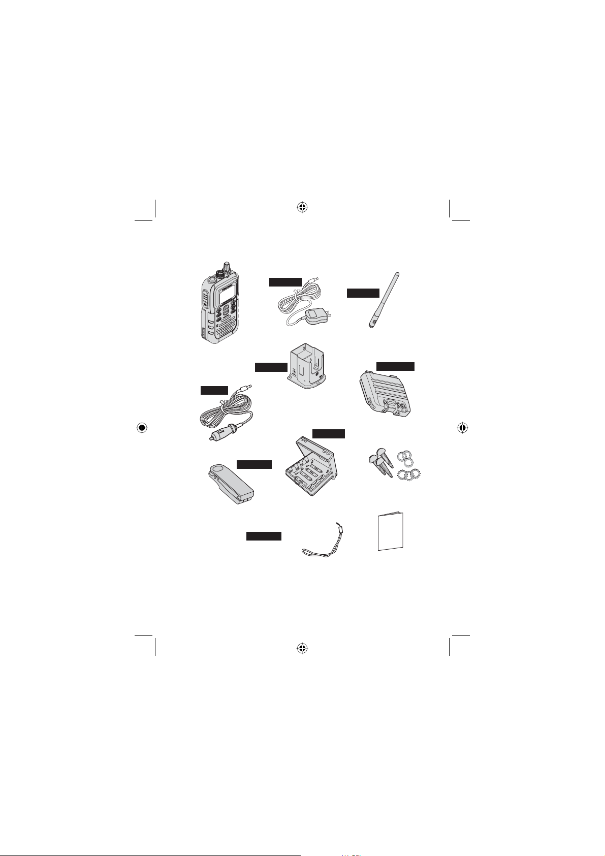
What’s Included
AC250
ANT150
AC Adapter
Antenna
VHF150 Radio
RSC250
DC250
BP250LI
Charging Cradle
BT250
Lithium Ion
Battery Pack
DC Adapter
CLIP250
Mounting
Belt Clip
Accessory ID
numbers such as
are provided to help you
order replacements
should that be neccessary.
CLIP250
Alkaline Battery Case
(batteries not included)
Wrist Strap
Hardware
OWNERS
MANUAL
Owners
Manual
If any of these items are missing from the box, contact
your West Marine dealer.
7West Marine VHF150 Radio Owner’s Manual
Page 8

FCC RF Exposure Information
WARNING! Read this information before using the radio
In August 1996 the Federal Communications Commission (FCC)
of the United States with its action in Report and Order FCC 96326 adopted an updated safety standard for human exposure to
radio frequency electromagnetic energy emitted by FCC regulated
transmitters. Those guidelines are consistent with the safety standard previously set by both U.S. and international standards bodies. The design of the radio complies with the FCC guidelines and
these international standards.
Never allow children to operate the radio without adult supervision
and the knowledge of the following guidelines.
WARNING! It is up to the user to properly operate this radio transmitter to insure safe operation. Please adhere to the following:
Use only the supplied or an approved antenna. Unauthorized antennas, modifi cations, or attachments could impair call quality,
damage the radio, or result in violation of FCC regulations.
Do not use the radio with a damaged antenna. If a damaged antenna comes into contact with the skin, a minor burn may result.
Please contact your local dealer for a replacement antenna.
Body-worn Operation This device was tested for typical bodyworn operations using the supplied belt-clip. To maintain compliance with FCC RF exposure requirements, body-worn operations
are restricted to the supplied belt-clip. For hand-held operation,
the radio should be held 1 inch from the user’s face. The use of
accessories that do not satisfy these requirements may not comply with FCC RF exposure requirements and should be avoided.
For more information about
website at www.fcc.gov
RF exposure, please visit the FCC
8
West Marine VHF150 Radio Owner’s Manual
Page 9

Lithium Ion Battery Pack Warning
•
This equipment contains a rechargeable Lithium Ion battery.
•
The rechargeable Lithium Ion battery contained in this
equipment may explode if disposed of in a fi re.
•
Do not short-circuit the Battery Pack.
•
Do not charge the rechargeable Lithium Ion battery used in
this equipment in any charger other than the one designed
to charge this battery as specifi ed in the owner’s manual.
Using another charger may damage the battery or cause
the Battery Pack to explode.
Lithium Ion batteries must be recycled or disposed of
properly.
Avoid exposing the Lithium Ion battery, attached or unattached to the radio, in direct sunlight, heated cars, or in areas with temperatures below -4°F (-20°C) or above +140°F
(+60°C). Exposing the chemical contained within the battery
pack to temperatures above +140°F (+60°C) may cause the
battery to rupture, fail, or reduce performance.
In case of exposure to the cell contents, wash the affected
area thoroughly, and seek medical attention.
9West Marine VHF150 Radio Owner’s Manual
Page 10

West Marine VHF 150
Introduction
Your West Marine VHF150 represents the latest in marine radio technology in a conveniently sized and rugged package.
It has features you’ll come to count on for day in and day out
use. The product combines size, value, and performance
that makes it a good choice for an all around marine communications radio.
Features
The VHF150 brings the following key features to make marine radio useful and easy:
•
Standard Marine channels (1 to 88) for the U.S., Cana-
da, and International waters — let you communicate with
standard marine radio operators.
•
National Oceanic and Atmospheric Administration
(NOAA) Weather channels — let you listen to the local
operational channel of the ten available.
•
NOAA Weather Alert — provides a siren tone warning of
a serious impending weather event and emergency weather warnings, broadcast by NOAA.
•
Emergency CH 16 (Coast Guard/Distress Hailing) and
CH9 (Calling/Hail Secondary) operation
•
Memory Scan — lets you store a channel (frequency) into
memory for scanning at another time using Dual or Triple
Watch or the standard Scan feature.
•
Triple and DualWatch Operation — In TripleWatch operation, the radio monitors the current channel, then the
Coast Guard/Distress/Hailing channels 16 and 9 in order.
In DualWatch, the radio monitors the channel in use (standard or weather) then channel 16 in that order.
10
West Marine VHF150 Radio Owner’s Manual
Page 11

•
Transmitter Power Level Select — lets you select an output power settings of 1, 2.5, and 5 watts except for certain
restricted channels.
•
Channel Select Keys — let you easily navigate up and
down the frequency list to the desired channel. They also
let you quickly choose all desired Radio Menu options.
•
Submersible — The radio is JIS7 compliant. This means it
remains watertight if submerged in 1 meter of water for 30
minutes.
•
Battery Power Level Display and Tone — clearly indicates fi ve levels of battery power. Sounds an alert tone
when battery power reaches a level before complete failure to operate.
•
Battery Save — during specifi c transmit, receive, and
weather alert operations, the radio powers down to extend
battery life.
•
Key Lock ON/OFF — lets you enable a keypad
lock to prevent accidental changes while powered on.
The feature becomes unlocked when powered off and on
again. You can also quickly disable the feature by pressing
and holding down this key.
11West Marine VHF150 Radio Owner’s Manual
Page 12
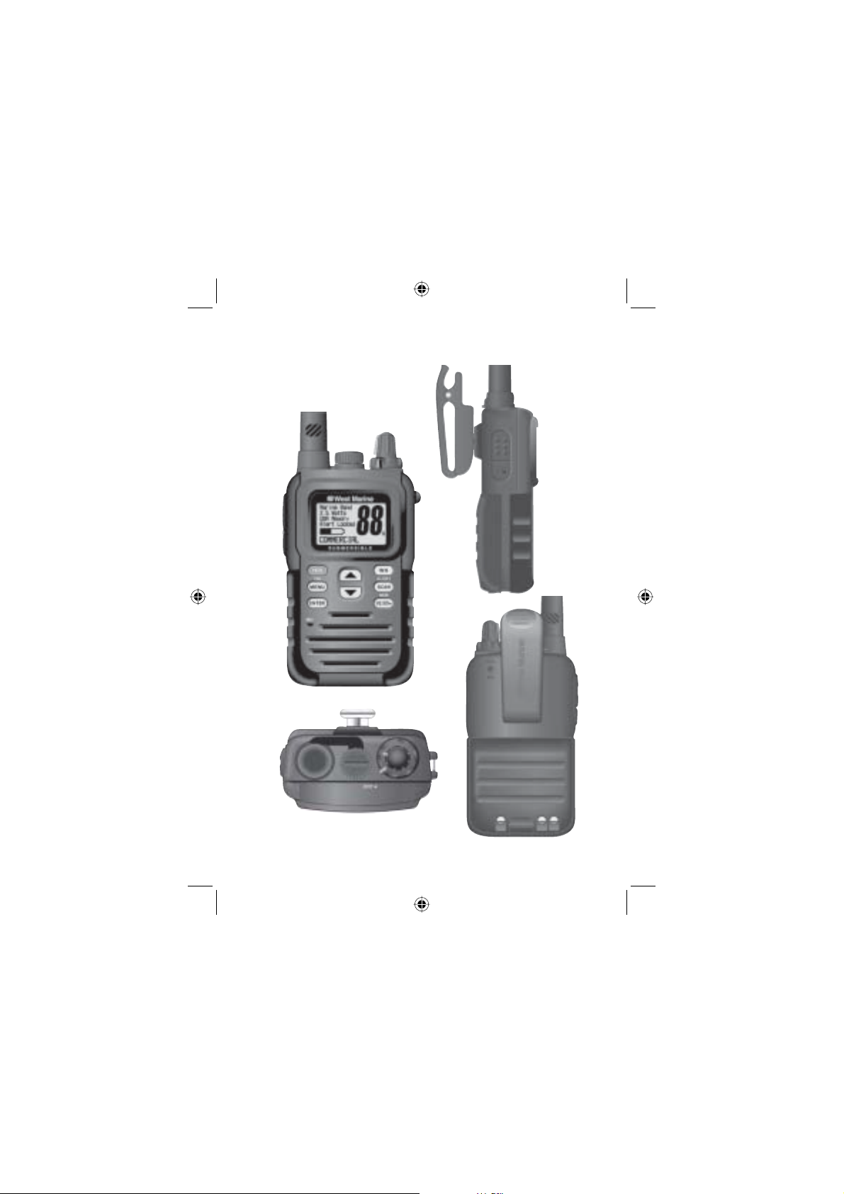
VHF 150 Controls
1
3
2
4
13
14
15
5
12
10
11
9
12
6
7
8
18
13
4
1
2
3
West Marine VHF150 Radio Owner’s Manual
16
16
17
16
Page 13

1. Antenna — Removable, and fl exible for convenience.
Watertight connector for reliability.
2. Watertight Ext. Speaker/Mic Jack — Unscrew the cap
and insert an approved mic/speaker to maintain submersability.
3. Volume-Power ON/OFF Control - Rotate to turn on pow-
er and set volume to a comfortable listening level.
4. Squelch Control — Rotate clockwise until the signal is
heard but not the noise.
5. Wrist Strap Anchor — Thread and loop the supplied
wrist strap to conveniently carry the radio.
6. WX/ALERT — Press to change the mode to Weather
Channel reception. Press and hold to activate the Weather
Alert feature.
7. SCAN/MEM — Press to set Memory Channel SCAN on or
off. Press and hold to store the current channel into memory.
8. 1/2.5/5w — Press to select the output power unless fi xed
by regulations.
9. 16/9/TRI — Press to switch immediately to the Coast
Guard/Distress/Hailing channel 16 or the secondary Calling
Hailing channel 9. Press and hold to enable Triple Watch or
Dual Watch monitoring.
10. MENU — Press to display the user-settable menu op-
tions.
11. ENTER — Press to select or store a chosen menu op-
tion.
12.
currently selected channel. Press and hold to change channels rapidly. Press to scroll through Radio Menu options.
13. Belt Clip —Squeeze and attach to your belt for conve-
— Press to select channels above or below your
13West Marine VHF150 Radio Owner’s Manual
Page 14
nient carrying.
14. PTT — Press to transmit.
15. Light/Lock — Press to activate the Backlight. Press and
hold to lock the Keypad.
16. Battery Connection Area and Battery Recharging
Contacts— Install the supplied Lithium Ion Rechargeable
Battery being sure to position the pack as shown in the section Batteries. To recharge the installed Lithium Ion battery,
place the VHF150 into the Charger Cradle. The contacts at
the bottom edge of the radio receive the required voltage and
current from the cradle to completely recharge the battery in
about 4 hours.
17. Battery Latch — Lift the latch to remove and replace
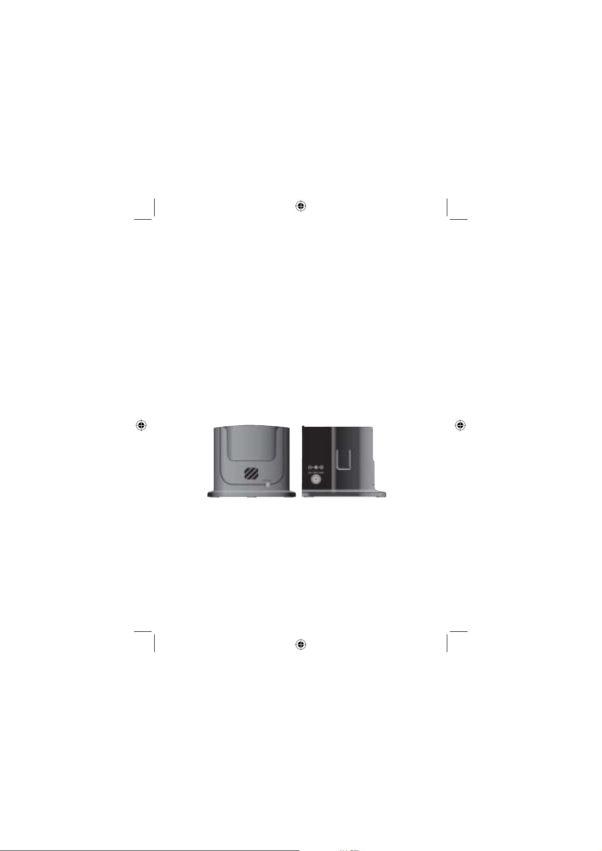
Radio Charger Cradle
21
20
19
the Lithium-Ion battery or to install the Alkaline Battery case.
18. MIC — Speak clearly into the microphone aperture when
transmitting for best results. Position the mic at least 4 inches from your mouth.
19. Front Charging Indicator — Lights when the battery
charges and goes off when charging completes.
20. DC Input Jack — Connect the AC adapter then plug the
adapter into a standard 120/240V AC outlet. The DC adapter
14
West Marine VHF150 Radio Owner’s Manual
Page 15
connects to a vessel’s 12V socket and this jack.
21. Charging Latch — Holds the radio in place when you
insert it into the cradle.
LCD Display
1 Watt or 2.5 Watts or 5 Watts — indicates present output
power. Not displayed when receiving weather frequencies.
Not displayed for those channels on which transmitting is
prohibited. The initial setting is 5W.
USA or INT or CAN (UIC) — indicates the frequency band in
use for marine operation.
Memory — displayed when the radio displays a channel
stored in memory.
Alert — displays when weather alert is enabled.
Scan — displays when the radio is set to scan mode.
TripleWatch or DualWatch — displayed when either mode
is active.
Locked — displayed when the keypad is locked.
Battery Level Icon — displays one of fi ve different indica-
tors to show the battery power level.
MODE Indicator Line — the bottom of the screen shows the
selected mode such as Standard Marine Channels, Weather,
Dual or Triple Watch, Transmitting, and more. For full details,
refer to the specifi c section of the manual.
15West Marine VHF150 Radio Owner’s Manual
Page 16

CHANNEL — shows the currently selected channel number
(1 to 88
A)
Owner Manual Conventions
To indicate a key, button, knob or other physical control, we
print the label in BOLD UPPER CASE. To indicate an LCD
(display) label, option, or selection, we use UPPER or Lower
Case italic labels such as MENU, 5 Seconds, etc.
You will also occasionally see an option labeled as (default).
This means that the option is set in the manner indicated at
the factory and is the setting when you fi rst apply power. If
you choose not to alter it, the default is the setting used by
the radio.
Indicator Sounds
The radio sounds several tones designed to convey important information. Become familiar with them to use the radio
more effectively.
Power On — a rising tone sounds to confi rm that power is
applied.
Keypad Touch Single Tone — sounds to confi rm you have
pressed a single key
Keypad Touch Double Tone — sounds to confi rm you
pressed and held down a key for 2 seconds.
Error Tone — sounds to indicate an invalid key press or operation.
PTT Error Tone — sounds to indicate an invalid press of the
PTT switch.
WX ALERT Tone — a rising and falling tone sounds when a
weather alert is received and decoded.
TX Time Out Tone — sounds when your continuous trans-
mitting time exceeds 5 minutes.
16
West Marine VHF150 Radio Owner’s Manual
Page 17
Batteries
Your West Marine VHF 150 comes equipped with a Lithium
Ion battery which snaps into the back of the radio and secures with a latch. The battery has a minimal charge when
shipped. Before use, place the radio in the Charging Cradle
and charge the battery for four hours. Note that unlike some
other types of rechargeable batteries, a Lithium Ion battery
can be “topped-off” as needed with no degration of performance.
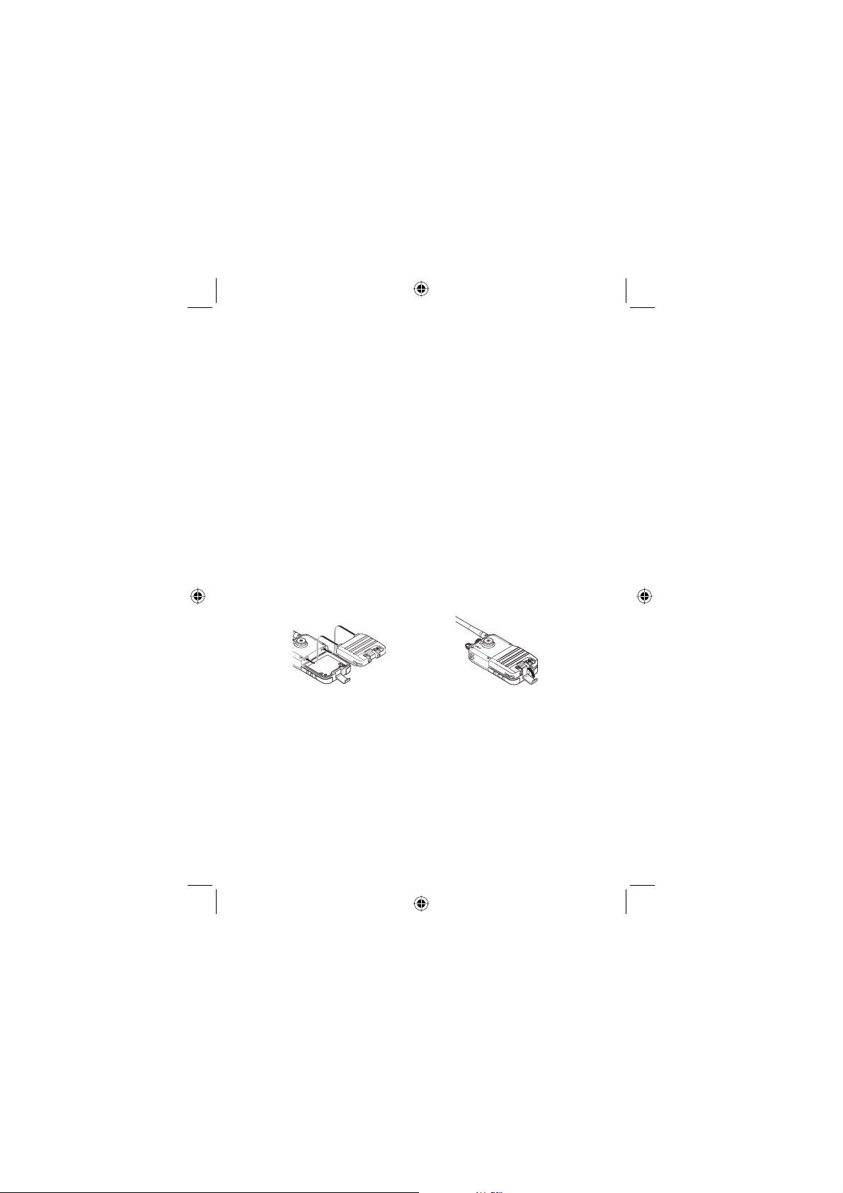
Installing the Lithium Ion Battery Pack
1.
To install the Lithium Ion Battery Pack, insert the upper contacts on the lower edge of the battery area on
the radio back as shown in the fi rst illustration.
2.
Lower the pack until it is fl at in the chamber
3.
Bring the locking latch up and lock it into place to secure the pack.
Using the Alkaline Battery Pack
The radio is supplied with a battery pack that can hold four
AAA type alkaline batteries (not supplied). For longest useful
life we suggest using an extra strength battery such as
Duracell Ultra
Note: When powering the radio by alkaline batteries,
transmit power is limited to a maximum of 2.5 watts.
®
batteries.
17West Marine VHF150 Radio Owner’s Manual
Page 18
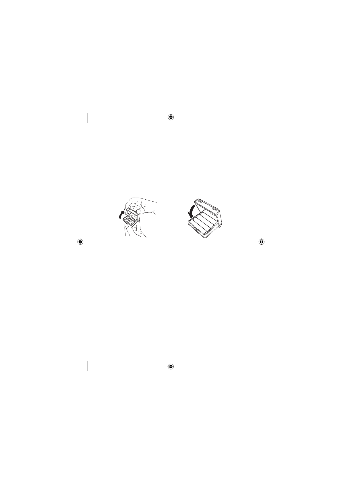
To install the four AAA batteries in the alkaline battery pack,
refer to the illustrations and the following steps.
1.
Hold the lower part of the pack and with the other
hand, lift the cover to reveal the contacts in the chamber. Note the polarity markings.
2.
Position the alkaline batteries according to the + and
- terminals and snap each into place.
Close the cover as shown.
3.
Using alkaline batteries let you continue to use the radio until
you have an opportunity to fully recharge your primary Lithium Ion Battery pack. Be sure to dispose of the alkaline batteries properly according to their package information.
Warning - although the design of the case prevents accidental charging of installed alkaline batteries, for safety, never
attempt to recharge alkaline batteries by defeating the case
design or recharging outside of the case.
Power AutoSave and Battery Life Indication
A special circuit conserves power when constant power is
not required. The battery powers down during receiving unless squelch is operating. However, the save feature does
not function during transmitting, weather alert settings or TripleWatch where power is always required. The Battery Power icon has 5 levels to indicate the voltage. When the battery
is almost dead, BATTERY LOW appears and blinks if you at-
18
West Marine VHF150 Radio Owner’s Manual
Page 19
tempt to transmit. If the battery icon continues to blink once
you stop pressing the PTT key, you must recharge/replace
the currently installed battery(s)
Mounting the Charging Cradle
You must charge the Lithium Ion Battery Pack before you
use the radio for the fi rst time. To facilitate convenient charg-
ing we suggest mounting the charger cradle to either a counter top or wall. Use the AC Adapter at home and the DC
Adapter on your boat.
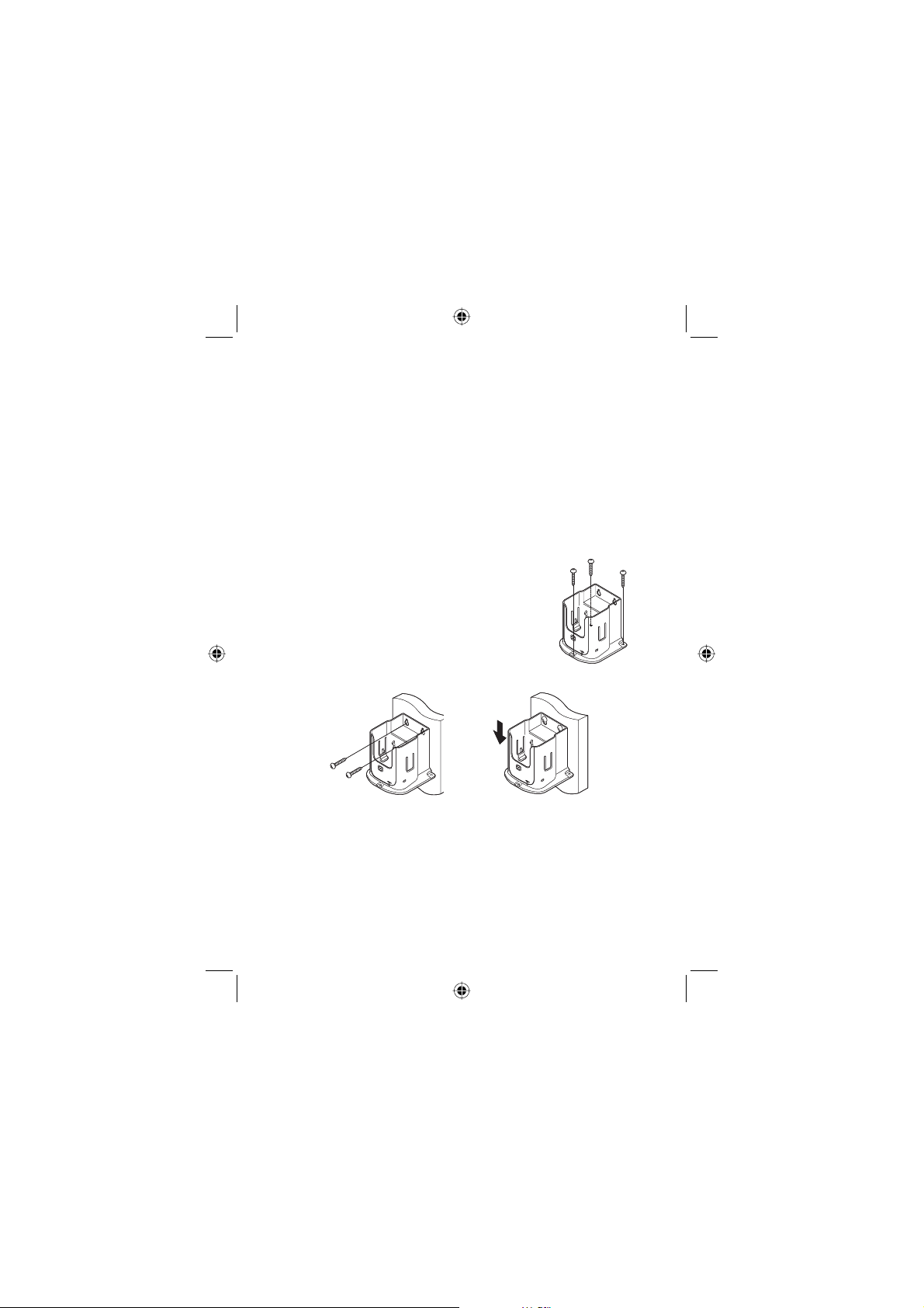
To Mount The Cradle on a Counter Top
Locate the three holes provided in the
fl ange surrounding the cradle. Using
the holes as a template, mark the surface. Center punch and drill three holes
to accomodate the provided screws and
washers.
Mounting on a Wall
Using the keyholes in the rear of the cradle as a template,
confi rm that the area on the wall has solid backing such as
a wooden beam. Then drill holes and use the screws and
washers provided. Otherwise, select other mounting hardware (not supplied) that is appropriate for the mounting material.
19West Marine VHF150 Radio Owner’s Manual
Page 20
Attaching the Belt Clip
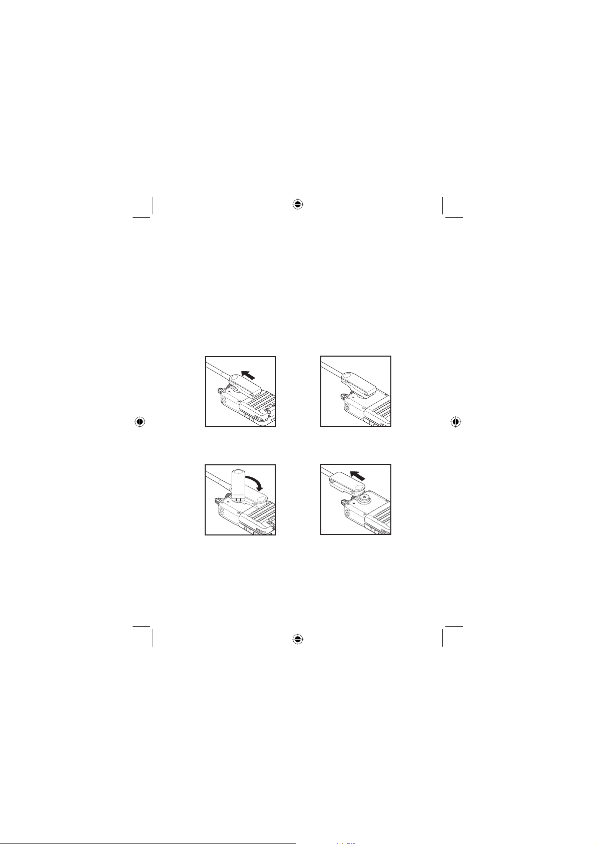
To conveniently carry the radio, attach the provided belt clip
as follows.
•
Align the clip mounting hole with the mounting post as
shown. Place the clip on the post and slide it in the direction of the arrow until you hear a click.
•
To remove the clip, rotate the clip so the indentation is toward the bottom of the radio. Move the clip in the direction
of the arrow and lift it off the post.
VOLSQVOL
SQ
Attach
VOLSQVOL
SQ
20
VOLSQVOL
SQ
VOLSQVOL
SQ
Remove
West Marine VHF150 Radio Owner’s Manual
Page 21
Operation — Getting Started
[
[
R
R
[
[
[
R
R
[
To start using your VHF150, follow the steps below.
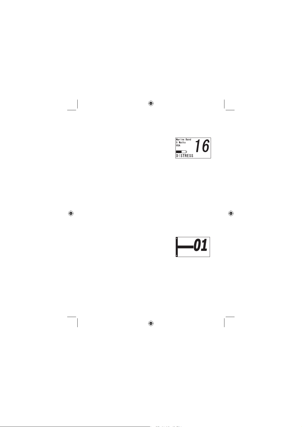
1.
Rotate VOLUME until the display lights and the Power On tone
sounds. The West Marine animated ‘splash’ screen displays followed
by the model number. Set the
control to a comfortable listening level. The display
shows channel 16 (default) in the US marine band,
a 5 watt level and the label DISTRESS at the bottom
edge. Press Ÿ or ź to change channels. The marine
channels begin at 01 and continue, in a closed loop,
through 88A. Using either key you can manually select a channel to use.
2.
Press WX to switch to the weather channels. Ten
channels are designated as weather channels. All
carry the same information. One will provide the best
reception for your particular area. Use Ÿ or ź to cycle through the ten channels until you locate the one
with the best reception. Press WX to return to marine
channels 1 to 88.
5CHGV
5CHGV
#865%QO
Operation – Selecting a
Channel
To receive transmissions and transmit
signals, select a working channel. When
you fi rst apply power, the screen displays the default band
(Marine USA), the default power setting (5W), and the battery power level icon.
To change the channel, press Ÿ or ź. The default channel
names appear next to the channel numbers along the left
border of the screen.
To cycle rapidly through the channels, press and hold either
#865%QO
#%)1PN
#%)1PN
#865%QO
#865%QO
#%QOOGTE
#%QOOGTE
/CTQ
/CTQ
/CT1
/CT1
T
T
/GOQT
/GOQT
T
T
#
#
21West Marine VHF150 Radio Owner’s Manual
Page 22
Ÿ or ź for about one-half second.
Operation – Transmitting Power Level
You can select the transmitting power for all channels except
those designated as or Low Power Channels (see the Status column of the Frequency Charts for more details).
Repeatedly press 1/2.5/5W. Each time you press the button,
the power output level changes and the corresponding icon
appears on the display.
Note: for those channels designated as 1W maximum, even
though you have set the power level to either 2.5 or 5W, 1W
is displayed and used. Channel 13 and 67 in the US is an
exception. Normally these channels are also designated for
normal operation as 1W channels. However, in emergency, if
you press and hold the PTT switch and at the same time you
momentarily press 1/2.5/5W, the power level changes
from 1 to 2.5 then to 5W.
You cannot override the 1W power level setting for
channels 75 and 76.
Operation – Transmitting
To transmit, follow the steps below.
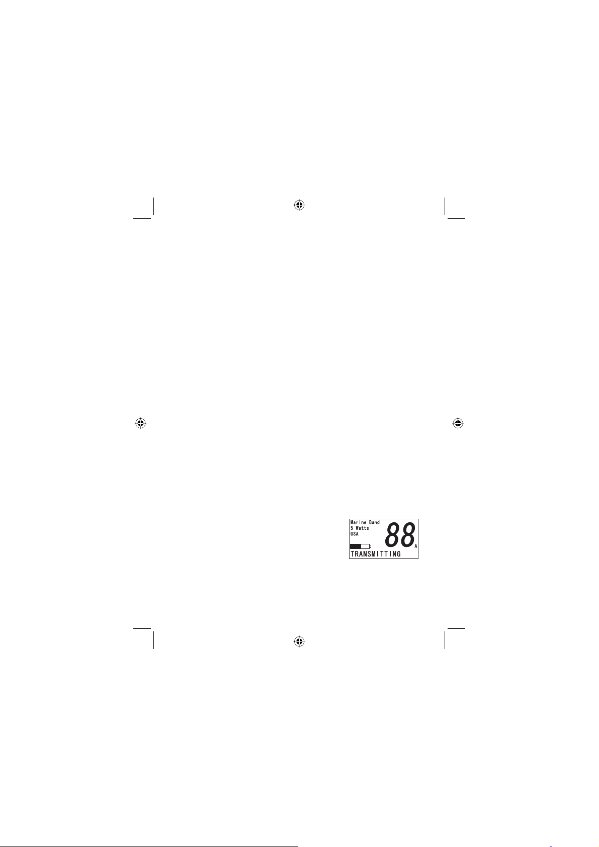
1.
Press Ÿ or ź to select a channel. The selected
channel number appears on the display along with
the country label, and the selected power setting.
2.
Press the PTT switch. TRANS-
MITTING appears at the bottom of
the screen and remains displayed
as long as you hold down the PTT
switch.
Note:
22
West Marine VHF150 Radio Owner’s Manual
Page 23

•
You cannot transmit on the weather frequencies. They are
designated ‘receive’ only. An error tones sounds when you
press the PTT switch and a weather channel is selected. The displayed weather channel number fl ashes, and
TRANSMITTING changes to RELEASE PTT KEY to remind you that you cannot transmit on the selected channel.
You cannot transmit on channel 70. It is reserved for digi-
•
tal data. If you attempt to transmit, you see RELEASE PTT
KEY on the bottom of the screen.
•
Do not hold down the PTT switch while turning on the radio. An error tone sounds and the same message appears.
•
Pressing PTT disables Scanning, Triple Watch checking
and Dual Watch checking. Transmitting starts on the currently displayed channel if that channel has a carrier (it is
a valid transmitting channel). If the channel has no carrier,
the fi rst press of PTT takes the radio out of scan mode.
Press PTT to activate transmitting.
Continuous transmitting is limited to 5 minutes by regula-
•
tions. After this time, an error tone sounds and RELEASE
PTT KEY displays. After you release PTT, pressing PTT re-
starts the 5-minute time interval again.
Operation – Using the Radio Menu Options
The VHF150 lets you select options that personalize your
use of the radio and makes using it more convenient.
Press MENU to access the multi-choice radio menu. RADIO
MENU appears at the top of the screen. Press MENU again
to return to the default marine mode or use Ÿ or ź to move
and highlight the desired menu option.
Note: if during any of the following operations you fail to
press a key or make a selection in more than 30 seconds,
the radio returns to standard marine mode.
23West Marine VHF150 Radio Owner’s Manual
Page 24
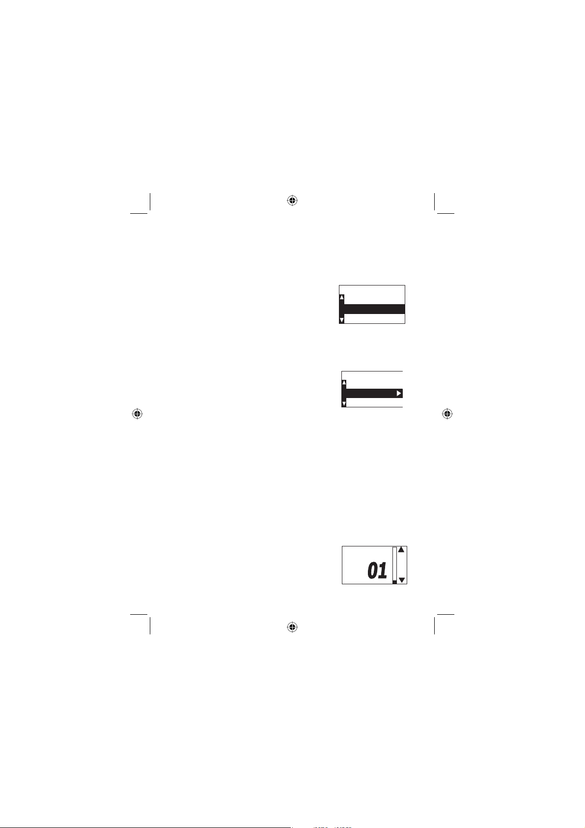
USA/CAN/INT (U.I.C.) — Settings
The radio is set as a factory default to the USA channel
frequencies. To change to either Canadian [CAN] or International [INT] channels, press MENU and highlight USA/CAN/
INT. Press ENTER. Press either Ÿ or ź
until the country Mode is highlighted.
Press ENTER to select it. Highlight EXIT
to exit the menu then press ENTER to
return to radio operation.
Note: the radio remembers the last selec-
7+%%*#00'.5
7+%%*#00'.5
75#/QFG
75#/QFG
%CPCFKCP/QFG
%CPCFKCP/QFG
+PVN/QFG
+PVN/QFG
'ZKV
'ZKV
tion setting you make when powered down.
Lamp (Backlight) Adjust
The backlight that provides convenient illumination of the keys and the
LCD has three settings.
Press Ÿ or ź to scroll to
1.
Lamp Adjust. Press ENTER.
LAMP ADJUST appears at the top of the screen.
Highlight either Always Off, Always On or Timer.
Press ENTER to select your choice.
2.
To set the on-time duration of the backlight, select Tim-
3.
er then highlight either 5 seconds (default), 30 seconds,
1 minute or 5 minutes then press ENTER. A double beep
sounds to confi rm your selection.
Scroll to EXIT and press ENTER to return to the RADIO
4.
MENU menu screen.
.#/2#&,756
.#/2#&,756
#NYC[U1HH
#NYC[U1HH
6KOGT
6KOGT
#NYC[U1P
#NYC[U1P
'ZKV
'ZKV
Adjusting Display Contrast
You can adjust the contrast setting of the
LCD for various viewing conditions.
Press Ÿ or ź from the RADIO
1.
24
West Marine VHF150 Radio Owner’s Manual
%QPVTCUV
%QPVTCUV
#FLWUV
#FLWUV
Page 25
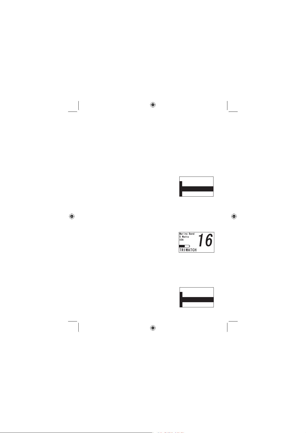
MENU screen to highlight Contrast Adjust.
Press Ÿ or ź to increase or decrease the level which
2.
is indicated by the number displayed (01 to 10)
and the thermometer bar. You see the screen contrast
change as you change the setting from 01 to 10.
Press ENTER to save your selection. Te display re-
3.
turns to the RADIO MENU screen.
Setting Dual or TriWatch
There are two specialty channels, 16, and
9. Channel 16 is the primary distress/
Coast Guard/Hailing channel while Channel 9 is typically the backup hailing/calling
channel for areas where there is higher
level of marine traffi c. Depending on your location, you can
choose to monitor both distress channel 16, the extra hailing
channel 9 as well as the radio channel you are otherwise using (TriWatch), or you can choose to only monitor channel 16
and your regular channel (DualWatch) which lets the radio
check each channel more frequently.
From the RADIO MENU screen,
1.
use Ÿ or ź to reach the Dual/Tri-
Watch option. Press ENTER.
Press either Ÿ or ź to reach ei-
2.
ther 16/9 TriWatch (default) or 16 DualWatch. Press
ENTER to select it. A double beep sounds and the radio returns to the RADIO MENU screen.
Press MENU again to return to the marine mode.
3.
&WCN6TK9CVEJ
&WCN6TK9CVEJ
6TK9CVEJ
6TK9CVEJ
&WCN9CVEJ
&WCN9CVEJ
'ZKV
'ZKV
Setting the Key Beep
Your VHF150 confi rms a key press by
sounding a short single or double beep
(default). You can disable this sound.
-';$''2
-';$''2
10
10
1((
1((
'ZKV
'ZKV
25West Marine VHF150 Radio Owner’s Manual
Page 26
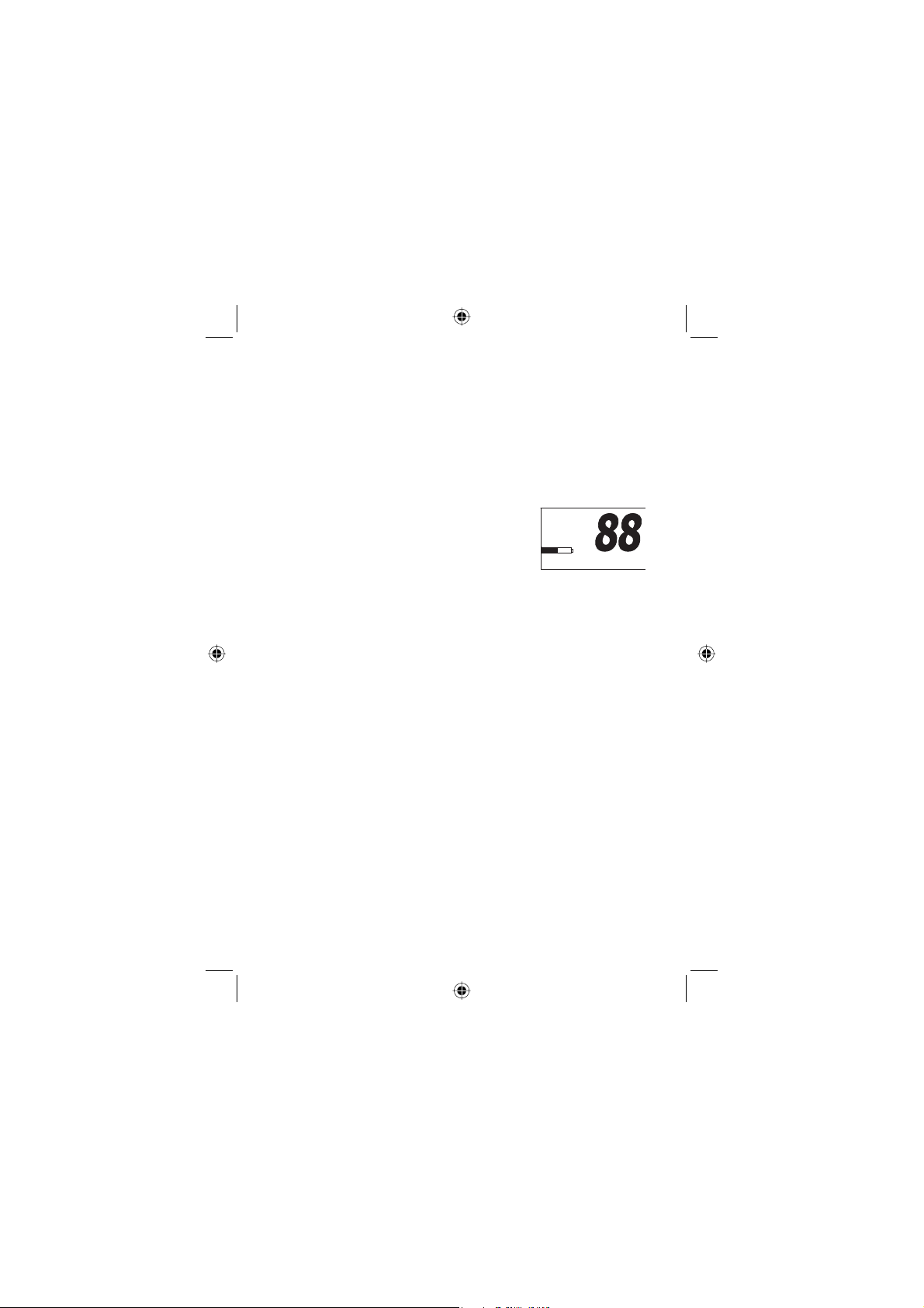
1.
From the RADIO MENU screen, press Ÿ or ź to
highlight the KEY BEEP option. Press ENTER to select it.
2.
Press Ÿ or ź to select On or Off or Exit . Press EN-
TER to save your selection. The display returns to the
RADIO MENU screen.
Setting the Key Lock
/CTKPG$CPF
To prevent keys from being accidentally
operated, set the Key Lock. Hold down
LIGHT/LOCK for 2-seconds. KEYPAD
LOCKED appears on the display bottom
for 3-seconds then returns to the standard screen. Locked remains next to the channel number to
remind you that the locked option is enabled.
During Key Lock mode, you can adjust only the following
controls:
•
PTT switch
•
Light/Lock key
•
Volume
•
Squelch
If any other control is used, an error tone sounds.
To disable the keypad lock, press and hold LIGHT/LOCK
for about 2-seconds or turn power off then on. KEYPAD UN-
LOCKED appears on the display.
Note: if the radio receives either a weather alert or decodes a
severe weather S.A.M.E. code transmission, the keypad automatically unlocks.
/CTKPG$CPF
9CVVU
9CVVU
75#
75#
.QEMGF
.QEMGF
-';2#&.1%-'&
-';2#&.1%-'&
#
#
26
West Marine VHF150 Radio Owner’s Manual
Page 27
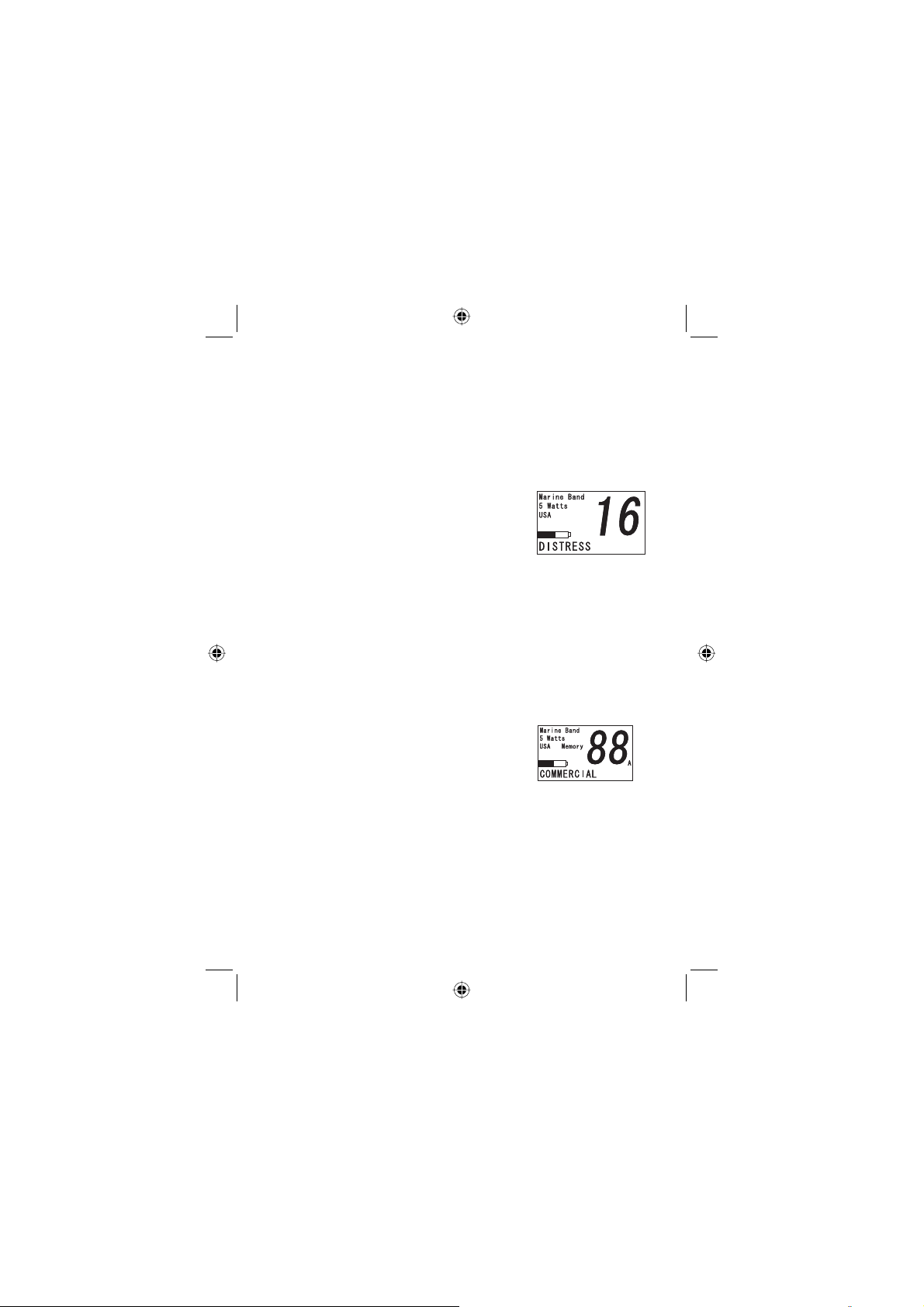
Manually Selecting Coast Guard/Distress/
Hailing Channels
In addition to using Triple or Dual Watch to monitor the Coast
Guard/Distress/Hailing channels, you can manually select
them at any time.
To select y o u r Coast Guard/Distress/Hailing channel,
repeatedly press 16/9/TRI. At the fi rst
press, the radio switches to channel 16,
the primary Coast Guard/Distress/Hailing
channel. 16 appears on the screen. Press
the button again to switch to channel 9, the
backup calling channel. 9 appears and NON COMMERCIAL
appears at the bottom. Press again to return to the standard
marine channels.
If you are listening to a weather (WX) channel and you press
16/9/TRI, the radio drops out of weather mode and switches to channel 16 and displays 16. if you are also set to TriWatch, the radio begin to check 16, then 9 then the marine
channel in use prior to selecting the weather mode.
Storing a Channel in Memory
Once you have stored channels in memory, you can set the radio to scan those
channels for activity. To select and store
a channel follow these steps.
Use Ÿ or ź until you reach a channel you want to store.
1.
Press and hold SCAN/MEM to store the channel in memo-
2.
ry. A single beep sounds to confi rm your action.
CHANNEL STORED appears at the bottom of the display.
3.
If you take no further action, the screen returns to the stan-
4.
dard marine screen in 3-seconds.
27West Marine VHF150 Radio Owner’s Manual
Page 28
5.
To remove a channel from memory, with the stored channel displayed, press and holdSCAN/MEM.
6.
To scan stored memory channels in several different
modes, see page 29
Using the Weather Channels
The radio receives ten National Oceanic and Atmospheric
Administration weather channels. Although the radio receives
all ten, one channel will be received best due to your
geographic location.
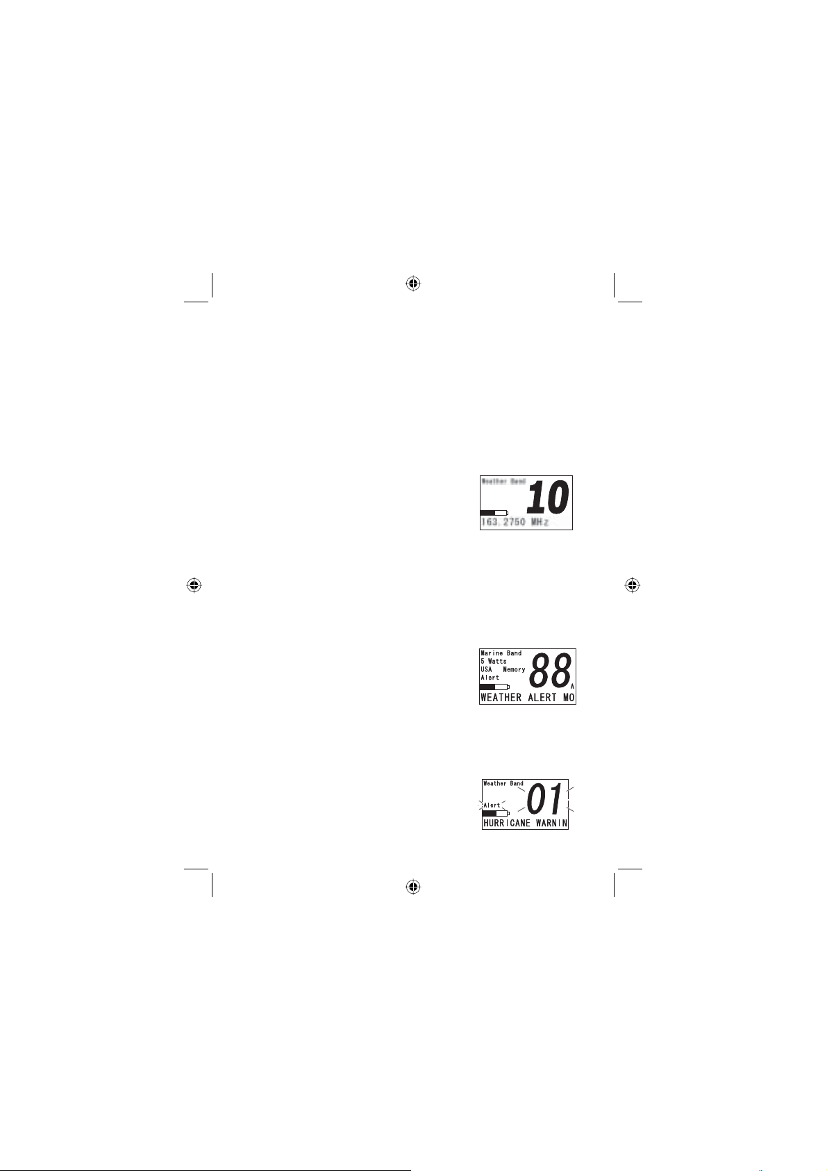
1.
Press WX/ALERT to activate the
weather band. The screen displays
WEATHER BAND at the upper left
and the channel number. The frequency of that channel number appears at the bottom
of the screen. You can fi nd a complete listing of the
weather channels in the Reference pages.
Note: the radio’s memory retains the channel that appears
when you switch to WX mode in memory when you turn off
the radio.
2.
To switch to the Alert mode, press and
hold down WX/ALERT for about 2 seconds. WEATHER ALERT MODE EN-
ABLED scrolls along the bottom of the
display.
If the radio receives a weather alert by means of either a
S.A.M.E by decoding the entered FIPS code or if the radio is
in the marine channel mode, dtecting the 1050Hz tone, the
radio sounds an alarm and displays the type of alert at the
bottom of he screen, such as HURRICANE WARNING.
Note: if the event code is longer than 16
characters, the display label scrolls across
the display bottom then changes to the
28
West Marine VHF150 Radio Owner’s Manual
Page 29
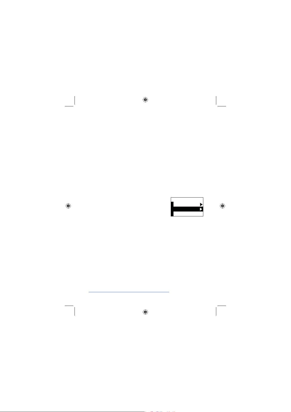
abbreviated format. Thus, HURRICANE WARNING (17 spaces) becomes HURRICANE WARN... and remains.
3.
To verify if the radio is in the ALERT mode, press and
hold WX/ALERT for about 2 seconds. If ALERT is active, WEATHER ALERT MODE ENABLE scrolls along the
screen bottom. This message appears for about 3 seconds
then returns to the marine standard screen.
If the radio is set to alert mode and you press and hold WX/
ALERT for about 2 seconds, the radio exits alert mode, and
the screen scrolls WEATHER ALERT MODE DISABLED.
For a listing of the full and abbreviated S.A.M.E. codes, see
the chart following the NOAA Channel Chart in the reference
section of this manual.
Adding FIPS Codes
To effectively use the Specifi c Area mes-
sage Encoding feature (S.A.M.E.) entering the code specifi c to your geographic
location is required. This system is known
as FIPS or Federal Information Processing
Standards codes (FIPS codes). They are a standardized set
of numeric codes issued by the National Institute of Standards
and Technology (NIST) to ensure uniform identifi cation of geo-
graphic entities through all federal government agencies. The
entities covered include: states and statistically equivalent
entities, counties and statistically equivalent entities, named
populated and related location entities (such as, places and
county subdivisions), and American Indian and Alaska Native
areas.
(+25%1&'5
(+25%1&'5
#FF
#FF
'ZKV
'ZKV
1.
Pess MENU. From the RADIO MENU screen, use Ÿ
or ź to select the FIPS option. The screen displays
FIPS Codes and lets you select ADD or Exit.
Note: Y ou can fi nd your area FIPS codes from
http://www.nws.noaa.gov/nwr/indexnw.htm.
29West Marine VHF150 Radio Owner’s Manual
Page 30

2.
R
[
[
R
[
[
Once you locate the code for your county or area, use Ÿ
or ź until the correct number appears on the screen then
press ENTER to select it.
3.
Enter all the codes you wish, then move to EXIT and EN-
TER to select it. The radio returns to the RADIO MENU
screen.
4.
Press MENU again to return to the marine mode.
Changing Channel Names
Each channel has a default name which
you can change. When a channel is allocated to a specifi c service, changing the
name on your radio can help make identifi cation faster and easier. Or you can
change the name to a member of your boating family such
as MOMS CHANNEL. You can use up to 16 characters.
1.
From the RADIO MENU, press Ÿ or ź to highlight
Channel Name.
2.
Press ENTER. Use Ÿ or ź to scroll
to the desired channel you wish to rename. Press ENTER. Then choose Re-
name , Default, or Exit. and select it.
3.
If you choose Rename, press either Ÿ or ź until the fi rst
letter or number of the new name appears. Press ENTER
to select it and move to the next character.
4.
When the name is complete, repeatedly press ENTER until the cursor reaches
the right end of the line. Then press EN-
TER again. A double beep sounds con-
fi rming the change and the display returns to the Channel
Name menu. Use Ÿ or ź to Exit and press ENTER.
%JCPPGN0COG
%JCPPGN0COG
#865%QO
#865%QO
#%)1PN[
#%)1PN[
#865%QO
#865%QO
2TGUUVJG72QT&190
2TGUUVJG72QT&190
UVQUGNGEV
UVQUGNGEV
CTTQYMG
CTTQYMG
VJGEJCTCEVGTVJGP
VJGEJCTCEVGTVJGP
TGUUVJGGPVGTMG
TGUUVJGGPVGTMG
%1#56)7#4&10.;
%1#56)7#4&10.;
30
West Marine VHF150 Radio Owner’s Manual
Page 31
Restoring Default Names
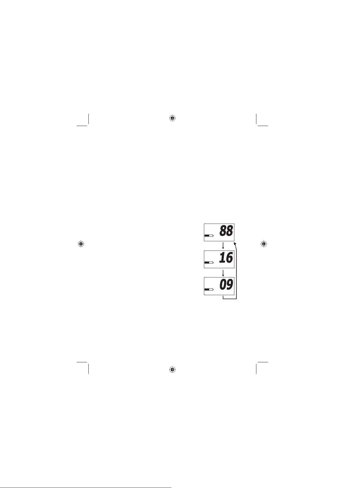
[
[
1.
If you want to restore all the factory default names,
use Ÿ or ź to highlight Default All located between
channel 88
A and Exit. Press ENTER to restore all the
original names. A double beep sounds to confi rm the
action.
2.
To restore only one name to default, highlight the
channel and use Ÿ or ź to next highlight Default.
Press ENTER to restore only that channel to the factory name setting.
Using the TripleWatch or DualWatch Mode
During setup of your VHF150, you have selected Triple or
DualWatch mode. The following shows you
how to use this valuable feature.
1.
To activate TripleWatch, from the
main marine screen, press and
hold 16/9/TRI for about 2 seconds.
The screen displays TRIWATCH
at the bottom and the radio begins
to check two additional channels in
rapid sequence every 2 seconds:
the currently selected marine channel, the Coast Guard/Distress/Hailing channel 16, then the backup
calling channel 9 before starting
with the current channel again.
2.
If you selected DualWatch during
setup, when activated, the radio fi rst checks the cur-
rent channel then it checks channel 16 before returning to the current marine channel. DUAL WATCH ap-
pears on the display bottom during this cycle.
3.
To exit either mode, press and hold 16/9/TRI for
about 2 seconds.
/CTKPG$CPF
/CTKPG$CPF
9CVVU
9CVVU
75#/GOQT
75#/GOQT
64+9#6%*
64+9#6%*
㪉㩷㫊㪼㪺
㪉㩷㫊㪼㪺
/CTKPG$CPF
/CTKPG$CPF
9CVVU
9CVVU
75#
75#
64+9#6%*
64+9#6%*
/CTKPG$CPF
/CTKPG$CPF
9CVVU
9CVVU
75#
75#
64+9#6%*
64+9#6%*
#
#
31West Marine VHF150 Radio Owner’s Manual
Page 32
Note:
[
[
•
If you enable TripleWatch or DualWatch from a Weather
Channel, the same watch cycle occurs. When the radio
checks the selected weather channel, the screen displays
WEATHER BAND at the top of the screen. When the radio checks Channel 16, Channel 9, or both, the screen
displays MARINE BAND at the upper left.
•
If you press SCAN, the TripleWatch or DualWatch functions as described above. Channels stored in memory
are scanned as usual. If you want to change the scanned
channels without ending the scan, press WX or PTT to
interrupt scanning. Then use Ÿ or ź to manually select
another marine channel. The watch check substitutes the
new marine channel.
In scan mode, the radio pauses on an active channel and
•
resumes scanning 2 seconds after the channel activity
ceases.
Using Scan with Triple Watch,
Dual Watch, or Weather Alert
Triple Watch and Dual Watch Only
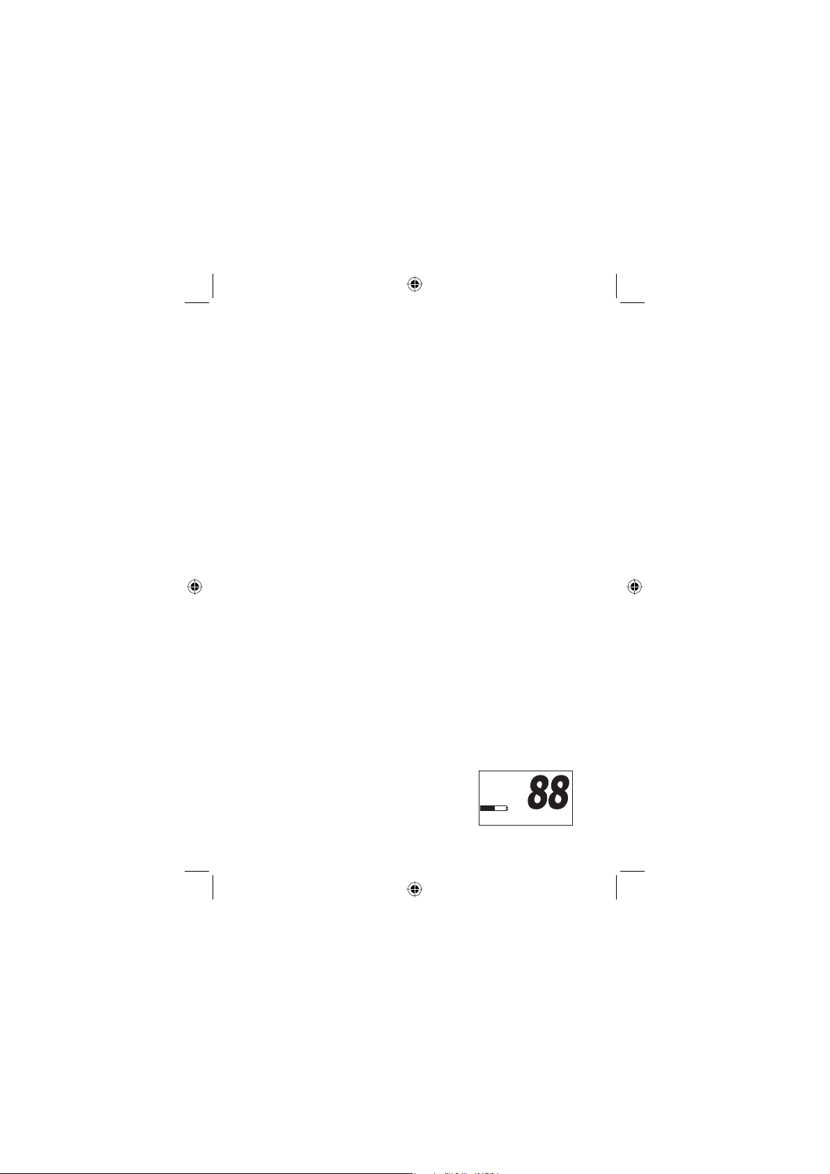
To activate normal channel SCAN mode, momentarily press
SCAN/MEM. The radio scans all the channels stored in
memory from lowest to highest. The display shows CHAN-
NEL SCAN at the bottom.
To initialiate TripleWatch scanning, press and hold 16/9/TRI.
Now TRIWATCH appears at the bottom while the scanning
changes to the following sequence: The memory channels
are scanned then the radio checks channel 16 then channel 9. If you have set Dual Watch as your
default mode, using the RADIO MENU,
channel 9 is not checked and DUAL-
WATCH SCAN appears on the display.
/CTKPG$CPF
/CTKPG$CPF
9CVVU
9CVVU
75#/GOQT
75#/GOQT
#NGTV
#NGTV
%*#00'.5%#0
%*#00'.5%#0
#
#
32
West Marine VHF150 Radio Owner’s Manual
Page 33

To disable Triple or Dual Watch and revert to scanning only
stored channels, press and hold 16/9/TRI for 2 seconds.
Channel 16 and 9 are no longer checked. The radio continues to scan only stored memory channels. CHANNEL SCAN
appears on the bottom and each channel number is displayed in sequence.
Both Watches and Weather Channel
If both the Weather Alert and the TripleWatch features are
enabled when you press SCAN/MEM, the radio starts checking the memory channels in ascending order. Then it checks
channel 16 every 2 seconds then channel 9 and fi nally, it
checks the active weather channel approximately every 8
seconds, looking for the alert tone (1050Hz). The radio then
repeats the cycle. If the radio detects a weather alert tone
during the check cycle, it remains on the weather channel
until you disable the weather mode. See the fl ow graphic.
Note:
•
During SCAN mode, if the radio detects a signal, it stops
scanning and remains on the detected channel for 2 seconds after the activity ends before resumption of scanning.
•
During scanning, you can press SCAN, 16/9/TRI, or WX/
ALERT to exit the scanning mode and return directly to the
marine channel display mode.
•
All channels, except the weather channels, can be stored
in memory. When you turn off the radio, all memory stored
channels are retained so that upon turning the radio on
again, they are immediately available.
33West Marine VHF150 Radio Owner’s Manual
Page 34
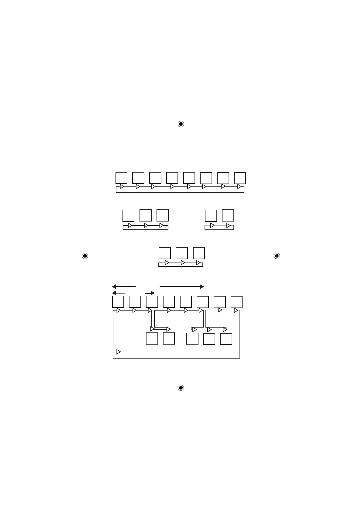
For Memory Stored Channels, Distress Ch. 16,
SCAN SEQUENCE
Backup Calling Ch. 9 and a WX channel
MEM MEM MEM MEM MEM MEM MEM MEM
Channel Scan of 8 Channels Stored in Memory
09
16
25
16
25
TripleWatch Scan of Marine Ch. 25,
Distress Ch. 16, and Hailing Ch. 9
WX
TripleWatch Scan of Weather Channel
(check for Alert 1050KHz tone),
Distress Ch. 16, and Hailing Ch. 9
~8 seconds
2 seconds
MEM
MEM MEM MEM MEM MEM MEM MEM
16 09
Channel Check
=
34
West Marine VHF150 Radio Owner’s Manual
DualWatch Scan of Marine Ch. 25,
and Distress Ch. 16
09
16
WX 16 09
Scan Sequence of Stored Channels,
TripleWatch, and TripleWatch with WX
Page 35

Using the External Speaker/Mic Jack
You can connect an optional external speaker-mic to this watertight jack. Unscrew the cap which is held by the rubber
cap-keeper to prevent loss. Insert the special gasketed plug
and screw down the shell which assures prevention of water
entering the jack. Two available units are HHSPM Speak-
er Mic and VOX100 Headset Mic. For details, consult your
West Marine dealer.
Resetting the VHF150
•
It is possible to completely reset the radio and restore all
the factory default settings. Should you choose to do this,
you must be aware that once you clear memory, there is
no undo.
•
However, if you desire to clear all your channels stored in
memory, reset all the renamed channels and restore the
scan settings to the factory default (as if you fi rst opened
the new box), carefully follow the steps below.
1.
With power off, press and hold
down Ÿ and 1/2.5/5W at the same time.
2.
While holding both keys down, turn on power.
3.
Release both keys.
4.
Press ENTER. Press 16/9/TRI. MEMORY CLEAR
appears.
5.
Turn power off then on, to complete the operation.
•
35West Marine VHF150 Radio Owner’s Manual
Page 36
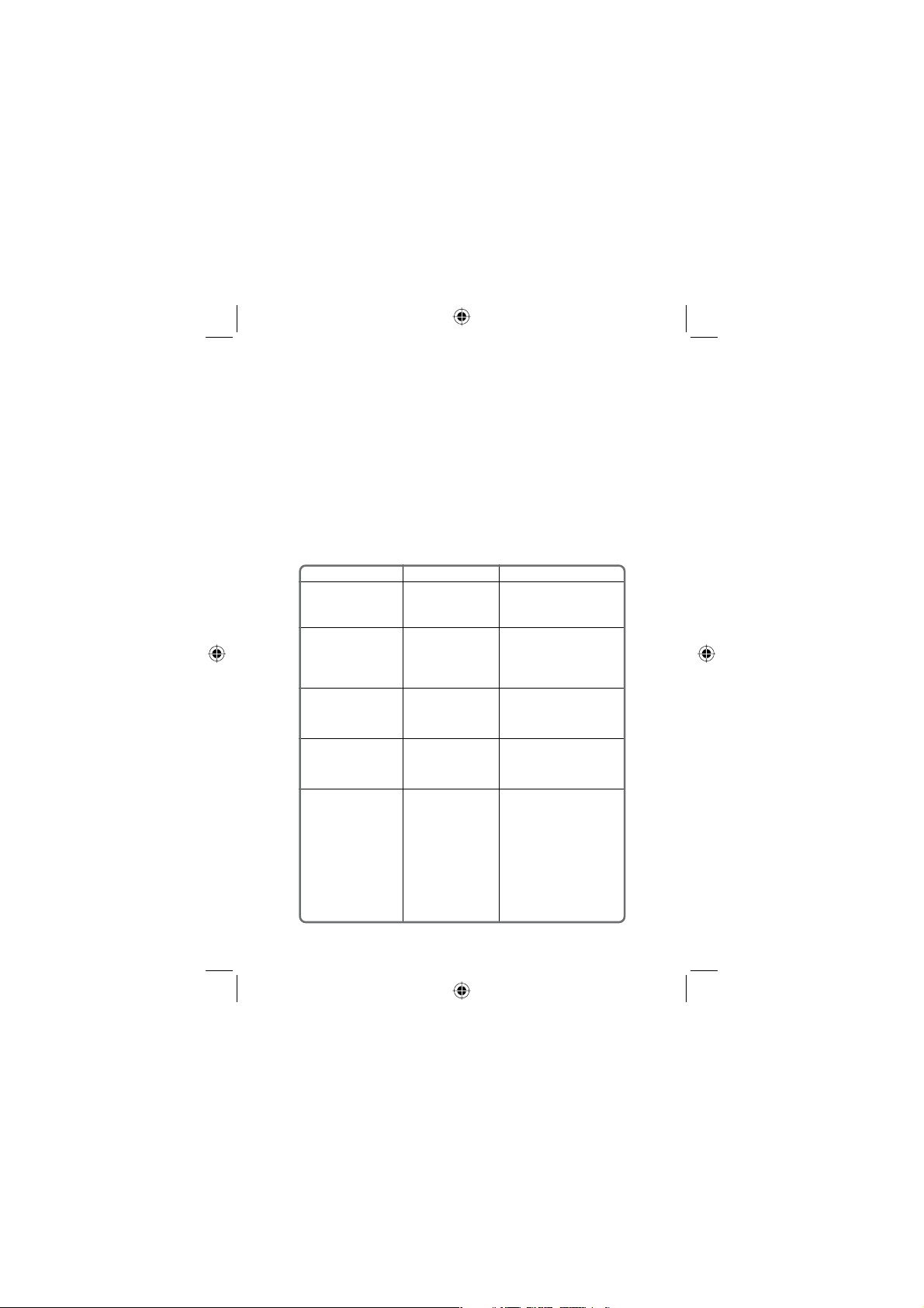
Troubleshooting
In the event that the radio fails to perform or clearly needs servicing,
please contact either 1-800 BOATING (1 800-262-8464) or your local West Marine dealer associate.
In case of the need to return it to our service center, be sure to include your return mailing information and detailed accounting of the
problems experienced and/or the service requested. Please use the
following shipping address:
2395 Bert Court
Hollister, CA 95023
Telephone (831) 761-4205
West Maine Electronics Repair Center
SYMPTOM
Won’t power On.
When the PTT is
pressed - Tx icon
comes on and another
radio can hear a “click”
but no audio is heard.
While scanning, the
radio stops on a
particular channel all of
the time.
There is noise on the
receiver that the
squelch will not
eliminate.
You have arranged to
communicate with
another VHF radio user
on a specic channel,
and you can not hear
them.
CAUSE
Low or Discharged
battery pack.
Bad microphone
element.
A source of noise is
nearby.
An external noise is
being generated by
some device.
You and the orther
user are using
dierent Country
Codes.
REMEDY
Recharge Lithium Ion battery.
Replace battery.
Use alkaline batteries
temporarily.
Send in for repair.
Turn Squelch clockwise to
reduce noise so that scan
function skips channel.
Either turn o the oending
device or contact that Mfg.
Regarding FCC part 15
“unintentional radiator ”.
Make sure that you are both
using the same Country
mode (USA, International, or
Canadian). Several channels
have the same numeric
designation, but are either
on dierent frequencies or
the channels are used for
dierent purpose. Channel
16, the Distress, Safety, and
Calling channel, is the same
on all three bands.
36
West Marine VHF150 Radio Owner’s Manual
Page 37
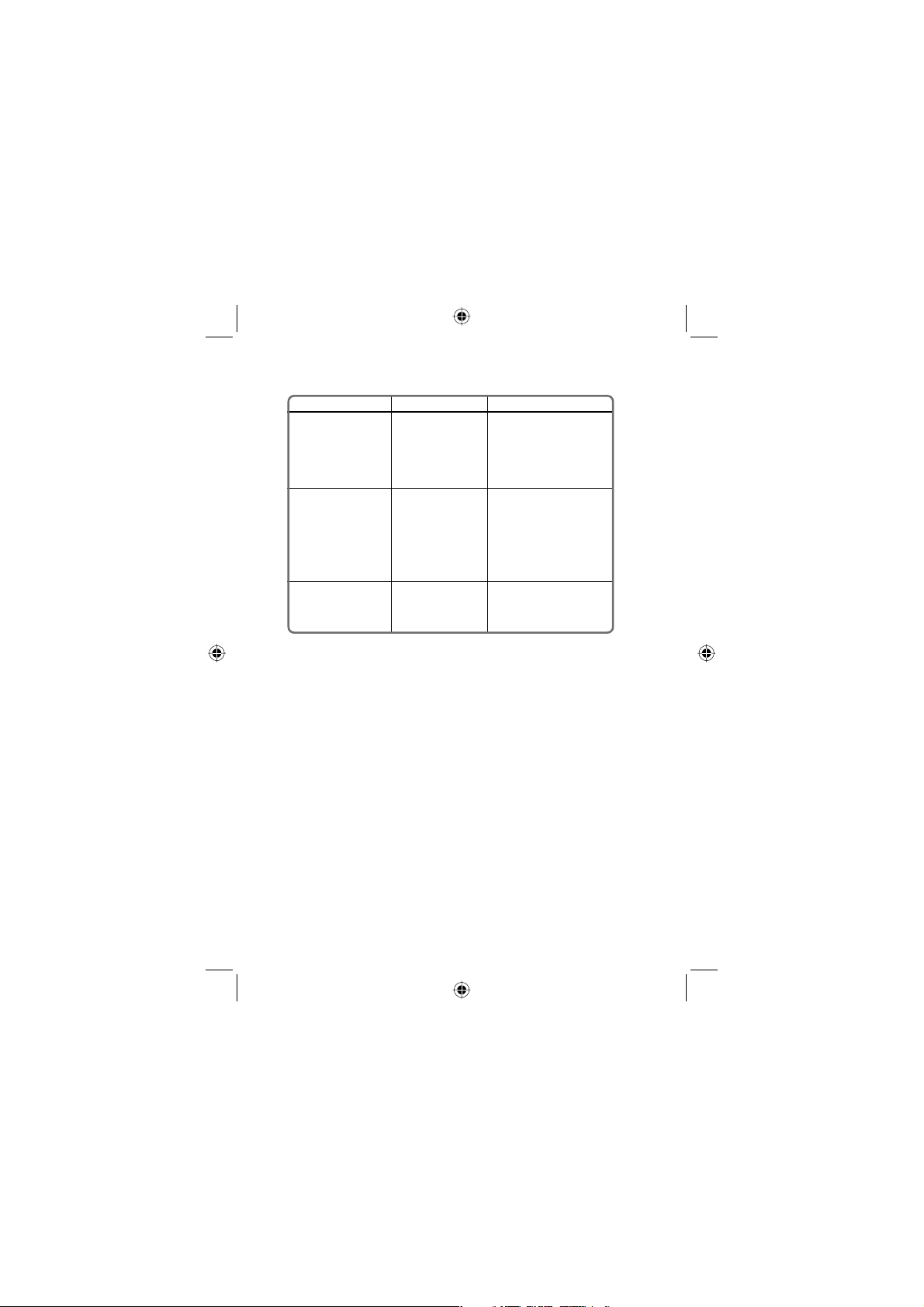
SYMPTOM
You can not change the
transmit power setting.
The SCAN key does
not start the scan
function.
You can hear
transmissions, but the
other radio cannot hear
you.
CAUSE
You are on a channel
which is limited to 1
watt transmit power
(e.g. Ch. 13) or you
are on a "receive
only" channel (e.g.
WX).
CAUSE 1: No
channels are in the
scan memory.
CAUSE 2: Squelch is
not adjusted correctly.
The transmit power is
set to low.
REMEDY
Change to an unrestricted
TX/RX channel.
REMEDY 1: Use the
MEM/SCAN key to enter
desired channels into the
scan memory.
REMEDY 2: Adjust the
squelch to the point that
background noise just
disappears.
Use the 1/2.5/5W key to
select a higher transmit
power setting.
37West Marine VHF150 Radio Owner’s Manual
Page 38
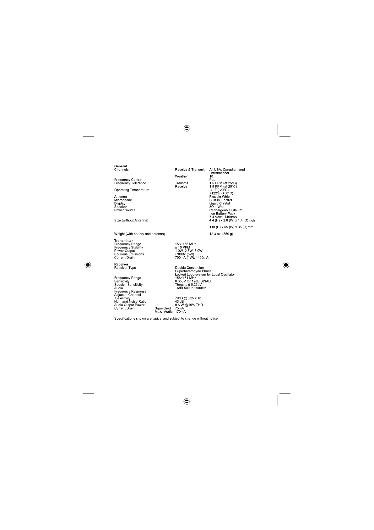
Specifi cations
38
West Marine VHF150 Radio Owner’s Manual
Page 39

Care and Maintenance
Your VHF150 is a precision of electronic equipment and you should treat
it accordingly. Due to the rugged design, very little maintenance is
required. However, a few precautions should be observed:
• If the antenna has been damaged, you should not transmit
except in the case of an emergency. A defective antenna may
cause damage to your radio.
• You are responsible for continued FCC technical compliance of
your radio.
West Marine
Electronics Repair Center
2395 Bert Court
Hollister, CA 95023
Please call us at 831-761-4205
39West Marine VHF150 Radio Owner’s Manual
Page 40
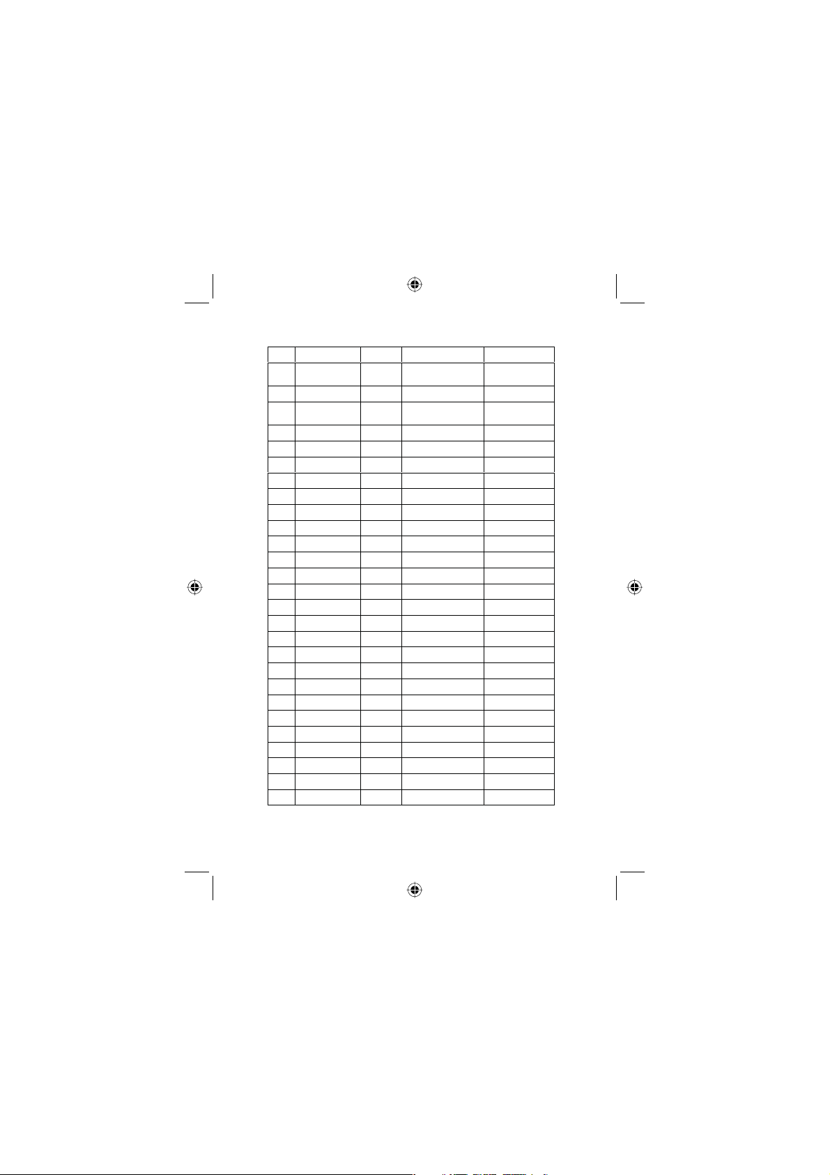
USA Channel Frequencies
RX Freq
TX Freq
156.0500
156.0500
156.1500
156.1500
156.2500
156.2500
156.3000
156.3000
156.3500
156.3500
156.4000
156.4000
156.4500
156.4500
156.5000
156.5000
156.5500
156.5500
156.6000
156.6000
156.6500
156.6500
156.7000
156.7000
Ch
No.
1”A”
3”A”
5“A”
6
7“A”
8
9
10
11
12
13
14
15 156.7500
16 156.8000
156.8000
17 156.8500
156.8500
18
156.9000
“A”
156.9000
19
156.9500
“A”
156.9500
20 161.6000
157.0000
20
157.0000
“A”
157.0000
21
157.0500
“A”
157.0500
22
157.1000
“A”
157.1000
23
157.1500
“A”
157.1500
24 161.8000
157.2000
25 161.8500
157.2500
26 161.9000
157.3000
27 161.9500
157.3500
28 162.0000
157.4000
Inhibit
Status Full Name 16 Char Name
Simplex VESSEL TRAFFIC
SYSTEM/
COMMERCIAL
Simplex COAST G UARD,GOVT
ONLY
Simplex VESSEL TRAFFIC
SYSTEM/COMMER
CIAL
Simplex INTER- SHIP SAFETY SAFETY
Simplex COMMERCIAL COMMERCIAL
Simplex COMMERCIAL COMMERCIAL
Simplex NON COMMERCIAL NON
Simplex COMMERCIAL COMMERCIAL
Simplex VESSEL TRAFFIC
SYSTEM
Simplex VESSEL TRAFFIC
SYSTEM
Simplex,1WBRIDGE TO BRIDGE BRIDGE TO
Simplex VESSEL TRAFFIC
SYSTEM
Receive
ENVIRONMENTAL ENVIRONMENTAL
Only
Simplex DISTRESS, SAFETY,
CALLING
Simplex,1WGOVT MARITIME
CONTROL
Simplex COMMERCIAL COMMERCIAL
Simplex COMMERCIAL COMMERCIAL
Duplex PORT OPERATION PORT
Simplex PORT OPERATION PORT
Simplex COAST GU ARD ONLY COAST GUARD
Simplex COAST G UARD COAST GUARD
Simplex COAST GU ARD ONLY COAST GUARD
Duplex MARINE OPERATOR MARINE
Duplex MARINE OPERATOR MARINE
Duplex MARINE OPERATOR MARINE
Duplex MARINE OPERATOR MARINE
Duplex MARINE OPERATOR MARINE
VTS/
COMMERCIAL
COAST GUARD
ONLY
VTS/
COMMERCIAL
COMMERCIAL
VESSEL TRAFFIC
VESSEL TRAFFIC
BRIDGE
VESSEL TRAFFIC
DISTRESS
GOVERNMENT
OPERATION
OPERATION
ONLY
ONLY
OPERATOR
OPERATOR
OPERATOR
OPERATOR
OPERATOR
40
West Marine VHF150 Radio Owner’s Manual
Page 41
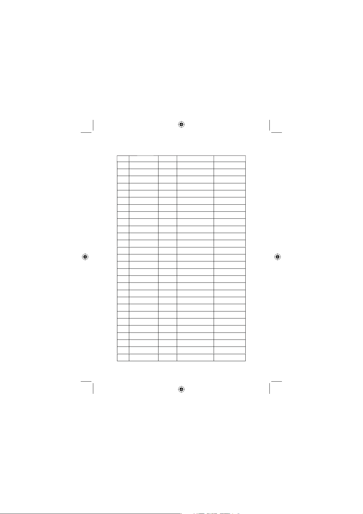
USA Channel Frequencies
28 162.0000
Ch No. RX Freq. TX Freq. Status Full Name 16 Char Name
157.4000
61
156.0750
“A”
156.0750
63
156.1750
“A”
156.1750
64
156.2250
“A”
156.2250
65
156.2750
“A”
156.2750
66
156.3250
“A”
156.3250
67 156.3750
156.3750
68 156.4250
156.4250
69 156.4750
156.4750
70 156.5250
71 156.5750
72 156.6250
73 156.6750
74 156.7250
75 156.7750
76 156.8250
77 156.8750
78
“A”
79
“A”
80
“A”
81
“A”
82
“A”
83
“A”
84 161.8250
85 161.8750
86 161.9250
87 161.9750
88 162.0250
88
“A”
Inhibit
156.5750
156.6250
156.6750
156.7250
156.7750
156.8250
156.8750
156.9250
156.9250
156.9750
156.9750
157.0250
157.0250
157.0750
157.0750
157.1250
157.1250
157.1750
157.1750
157.2250
157.2750
157.3250
157.3750
157.4250
157.4250
157.4250
Duplex MARINE OPERATOR MARINE
Simplex COAST GUARD COAST GUARD
Simplex VESSEL TRAFFIC
Simplex COMMERCIAL COMMERCIAL
Simplex PORT OPERATION PORT
Simplex PORT OPERATION PORT
Simplex,1WBRIDGE TO BRIDGE BRIDGE TO
Simplex NON COMMERCIAL NON
Simplex NON COMMERCIAL NON
Receive
Only
Simplex NON COMMERCIAL NON
Simplex NON COMMERCIAL
Simplex PORT OPERATION PORT
Simplex PORT OPERATION PORT
Simplex,1WPORT OPERATION PORT
Simplex,1WPORT OPERATION PORT
Simplex,1WPORT OPERATION
Simplex NON COMMERCIAL NON
Simplex COMMERCIAL COMMERCIAL
Simplex COMMERCIAL COMMERCIAL
Simplex COAST GUARD COAST GUARD
Simplex COAST GUARD COAST GUARD
Simplex GOVERNMENT GOVERNMENT
Duplex MARINE OPERATOR MARINE
Duplex MARINE OPERATOR MARINE
Duplex MARINE OPERATOR MARINE
Duplex MARINE OPERATOR MARINE
Duplex MARINE OPERATOR MARINE
Simplex COMMERCIAL (SHIP-
SYSTEM
DIGITAL SELECTIVE
CALLING
(SHIP-SHIP)
(SHIP-SHIP)
SHIP)
OPERATOR
VESSEL TRAFFIC
OPERATION
OPERATION
BRIDGE
COMMERCIAL
COMMERCIAL
DSC RECEIVE
ONLY
COMMERCIAL
NON
COMMERCIAL
OPERATION
OPERATION
OPERATION
OPERATION
PORT
OPERATION
COMMERCIAL
OPERATOR
OPERATOR
OPERATOR
OPERATOR
OPERATOR
COMMERCIAL
41West Marine VHF150 Radio Owner’s Manual
Page 42
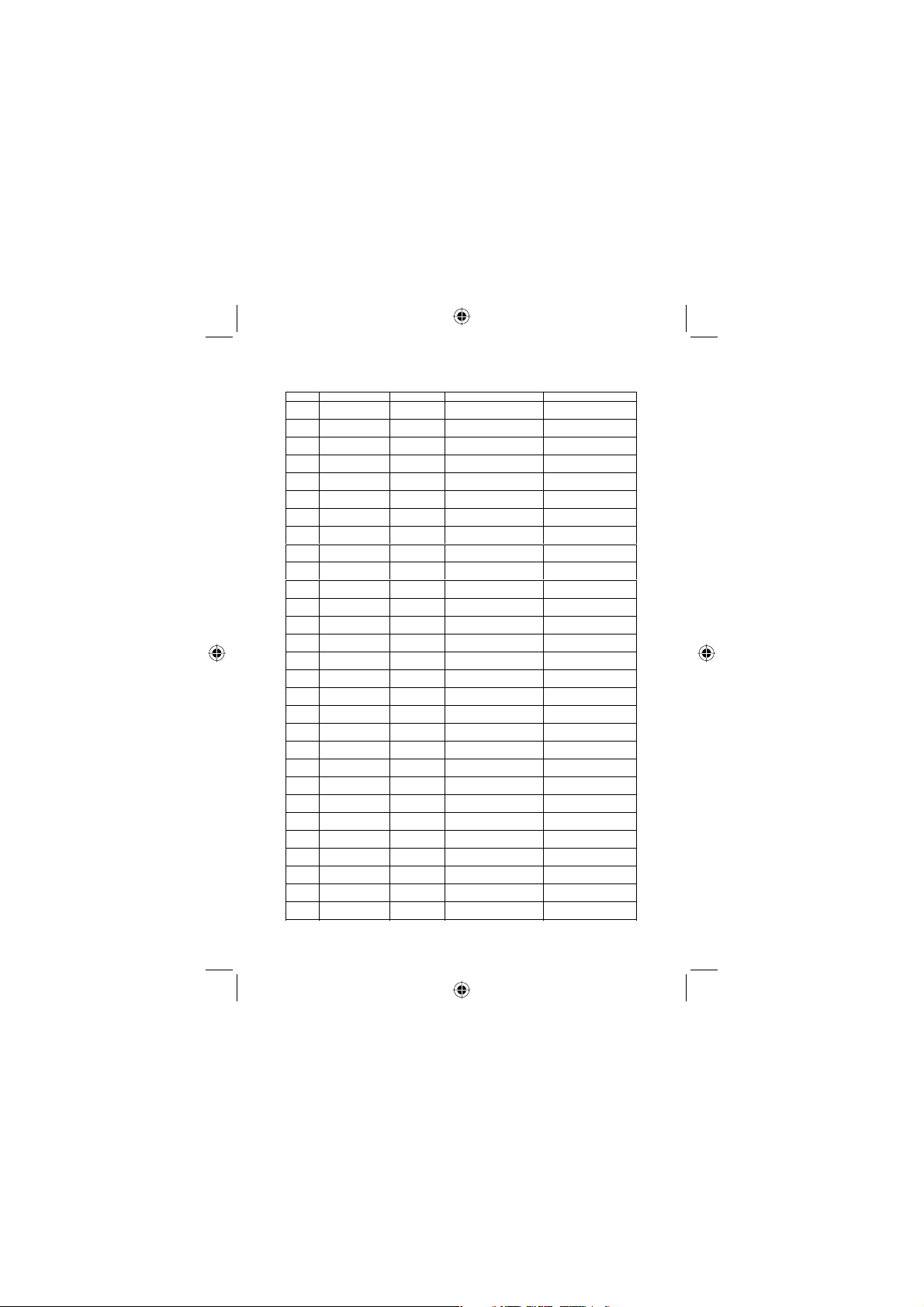
Canadian Channel Frequencies
Ch No. RX Freq TX Freq Status Full Name 16 Char Name
1 160.6500
156.0500
2 160.7000
156.1000
3 160.7500
156.1500
4 “A” 156.2000
156.2000
5 “A” 156.2500
156.2500
6 156.3000
156.3000
7 “A” 156.3500
156.3500
8 156.4000
156.4000
9 156.4500
156.4500
10 156.5000
156.5000
11 156.5500
156.5500
12 156.6000
156.6000
13 156.6500
156.6500
14 156.7000
156.7000
15 156.7500
156.7500
16 156.8000
156.8000
17 156.8500
18 “A” 156.9000
19 “A” 156.9500
21 “A” 157.0500
22 “A” 157.1000
156.8500
156.9000
156.9500
20 161.6000
157.0000
157.0500
157.1000
23 161.7500
157.1500
24 161.8000
157.2000
25 161.8500
157.2500
26 161.9000
157.3000
27 161.9500
157.3500
28 162.0000
157.4000
60 160.6250
156.0250
Duplex MARINE OPERATOR MARINE OPERATOR
Duplex MARINE OPERATOR MARINE OPERATOR
Duplex MARINE OPERATOR MARINE OPERATOR
Simplex CANADIAN COAST
Simplex VESSEL TRAFFIC
Simplex INTER-SHIP SAFETY SAFETY
Simplex COMMERCIAL COMMERCIAL
Simplex COMMERCIAL COMMERCIAL
Simplex BOATER CALLING
Simplex COMMERCIAL COMMERCIAL
Simplex VESSEL TRAFFIC
Simplex VESSEL TRAFFIC
Simplex, 1W BRIDGE TO BRIDGE BRIDGE TO BRIDGE
Simplex VESSEL TRAFFIC
Simplex ENVIRONMENTAL ENVIRONMENTAL
Simplex DISTRESS, SAFETY,
Simplex, 1W STATE CONTROL STATE CONTROL
Simplex COMMERCIAL COMMERCIAL
Simplex CANADIAN COAST
Duplex, 1W PORT OPERATION PORT OPERATION
Simplex CANADIAN COAST
Simplex CANADIAN COAST
Duplex CANADIAN COAST
Duplex MARINE OPERATOR MARINE OPERATOR
Duplex MARINE OPERATOR MARINE OPERATOR
Duplex MARINE OPERATOR MARINE OPERATOR
Duplex MARINE OPERATOR MARINE OPERATOR
Duplex MARINE OPERATOR MARINE OPERATOR
Duplex MARINE OPERATOR MARINE OPERATOR
GUARD
SYSTEM
CHANNEL
SYSTEM
SYSTEM
SYSTEM
CALLING
GUARD
GUARD
GUARD
GUARD
COAST GUARD
VESSEL TRAFFIC
CALLING
VESSEL TRAFFIC
VESSEL TRAFFIC
VESSEL TRAFFIC
DISTRESS
COAST GUARD
COAST GUARD
COAST GUARD
COAST GUARD
42
West Marine VHF150 Radio Owner’s Manual
Page 43
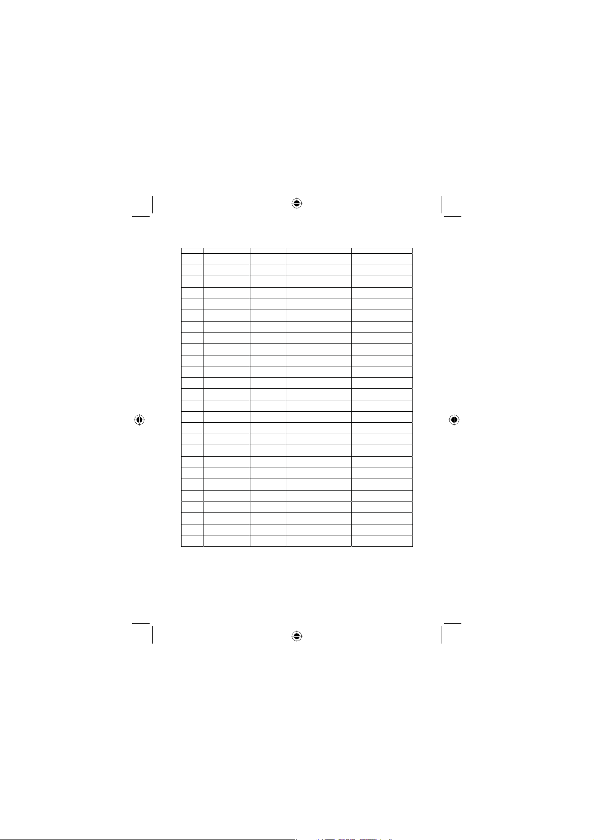
Canadian Channel Frequencies
Ch No. RX Freq TX Freq Status Full Name 16 Char Name
64 “A” 156.2250
65 “A” 156.2750
66 “A” 156.3250
78 “A” 156.9250
79 “A” 156.9750
80 “A” 157.0250
81 “A” 157.0750
82 “A” 157.1250
83 “A” 157.1750
156.2250
156.2750
156.3250
67 156.3750
156.3750
68 156.4250
156.4250
69 156.4750
156.4750
70 156.5250
71 156.5750
72 156.6250
73 156.6750
74 156.7250
75 156.775
76 156.825
77 156.8750
83 161.7750
84 161.8250
85 161.8750
86 161.9250
87 161.9750
88 162.0250
Inhibit
156.5750
156.6250
156.6750
156.7250
156.775
156.825
156.8750
156.9250
156.9750
157.0250
157.0750
157.1250
157.1750
157.1750
157.2250
157.2750
157.3250
157.3750
157.4250
Simplex MARINE OPERATOR MARINE OPERATOR
Simplex SEARCH AND RESCUE SEARCH & RESCUE
Simplex, 1W PORT OPERATION PORT OPERATION
Simplex BRIDGE TO BRIDGE BRIDGE TO BRIDGE
Simplex NON COMMERCIAL NON COMMERCIAL
Simplex NON COMMERCIAL NON COMMERCIAL
Receive Only DIGITAL SELECTIVE
Simplex NON COMMERCIAL NON COMMERCIAL
Simplex NON COMMERCIAL NON COMMERCIAL
Simplex PORT OPERATION PORT OPERATION
Simplex PORT OPERATION PORT OPERATION
Simplex, !W PORT OPERATION PORT OPERATION
Simplex, 1W PORT OPERATION PORT OPERATION
Simplex, 1W PORT OPERATION PORT OPERATION
Simplex INTER SHIP INTER SHIP
Simplex INTER SHIP INTER SHIP
Simplex INTER SHIP INTER SHIP
Simplex CANADIAN COAST
Simplex CANADIAN COAST
Duplex CANADIAN COST GUARD COAST GUARD
Simplex CANADIAN COAST
Duplex MARINE OPERATOR MARINE OPERATOR
Duplex MARINE OPERATOR MARINE OPERATOR
Duplex MARINE OPERATOR MARINE OPERATOR
Duplex MARINE OPERATOR MARINE OPERATOR
Duplex MARINE OPERATOR MARINE OPERATOR
CALLING
GUARD
GUARD
GUARD
DSC RECEIVE ONLY
COAST GUARD
COAST GUARD
COAST GUARD
43West Marine VHF150 Radio Owner’s Manual
Page 44
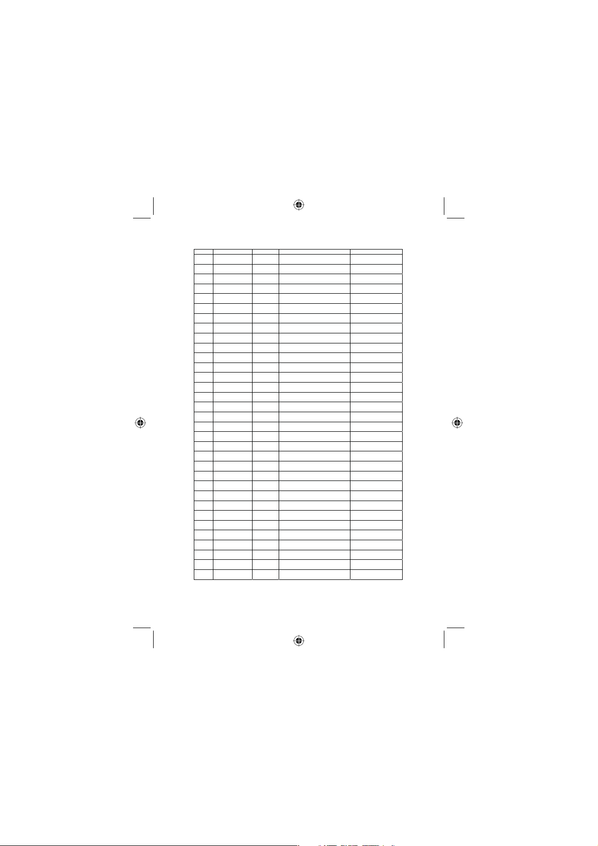
International Channel Frequencies
Ch No. RX Freq TX Freq Status FullName 16 Char Name
1 160.6500
156.0500
2 160.7000
156.1000
3 160.7500
156.1500
4 160.8000
156.2000
5 160.8500
156.2500
6 156.3000
156.3000
7 160.9500
156.3500
8 156.4000
156.4000
9 156.4500
156.4500
10 156.5000
156.5000
11 156.5500
156.5500
12 156.6000
156.6000
13 156.6500
156.6500
14 156.7000
156.7000
15 156.7500
156.7500
16 156.8000
156.8000
17 156.8500
156.8500
18 161.5000
156.9000
19 161.5500
156.9500
20 161.6000
157.0000
21 161.6500
157.0500
22 161.7000
157.1000
23 161.7500
157.1500
24 161.8000
157.2000
25 161.8500
157.2500
26 161.9000
157.3000
27 161.9500
157.3500
28 162.0000
157.4000
60 160.6250
156.0250
61 160.6750
156.0750
62 160.7250
156.1250
63 160.7750
156.1750
64 160.8250
156.2250
Duplex MARINE OPERATOR MARINE OPERATOR
Duplex MARINE OPERATOR MARINE OPERATOR
Duplex MARINE OPERATOR MARINE OPERATOR
Duplex MARINE OPERATOR MARINE OPERATOR
Duplex MARINE OPERATOR MARINE OPERATOR
Simplex INTER-SHIP SAFETY SAFETY
Duplex MARINE OPERATOR MARINE OPERATOR
Simplex COMMERCIAL (SHIP-SHIP) COMMERCIA L
Simplex BOATER CALLING CHANNEL CALLING
Simplex COMME RCIAL COMMERCIAL
Simplex VESSEL TRAFFIC SYSTEM VESSEL TRAFFIC
Simplex VESSEL TRAFFIC SYSTEM VESSEL TRAFFIC
Simplex BRIDGE TO BRIDGE BRIDGE TO BRIDGE
Simplex VESSEL TRAFFIC SYSTEM VESSEL TRAFFIC
Simplex,1WENVIRONMENTAL ENVIRONMENTAL
Simplex DISTRESS, SAFETY, CALLING DISTRESS
Simplex,1WGOVT MARINE CONTROL GOVERNMENT
Duplex PORT OPERATION PORT OPERATION
Duplex COMMERCIAL COMMERCIAL
Duplex PORT OPERATION PORT OPERATION
Duplex PORT OPERATION PORT OPERATION
Duplex PORT OPERATION PORT OPERATION
Duplex MARINE OPERATOR MARINE OPERATOR
Duplex MARINE OPERATOR MARINE OPERATOR
Duplex MARINE OPERATOR MARINE OPERATOR
Duplex MARINE OPERATOR MARINE OPERATOR
Duplex MARINE OPERATOR MARINE OPERATOR
Duplex MARINE OPERATOR MARINE OPERATOR
Duplex MARINE OPERATOR MARINE OPERATOR
Duplex MARINE OPERATOR MARINE OPERATOR
Duplex MARINE OPERATOR MARINE OPERATOR
Duplex MARINE OPERATOR MARINE OPERATOR
Duplex MARINE OPERATOR MARINE OPERATOR
44
West Marine VHF150 Radio Owner’s Manual
Page 45
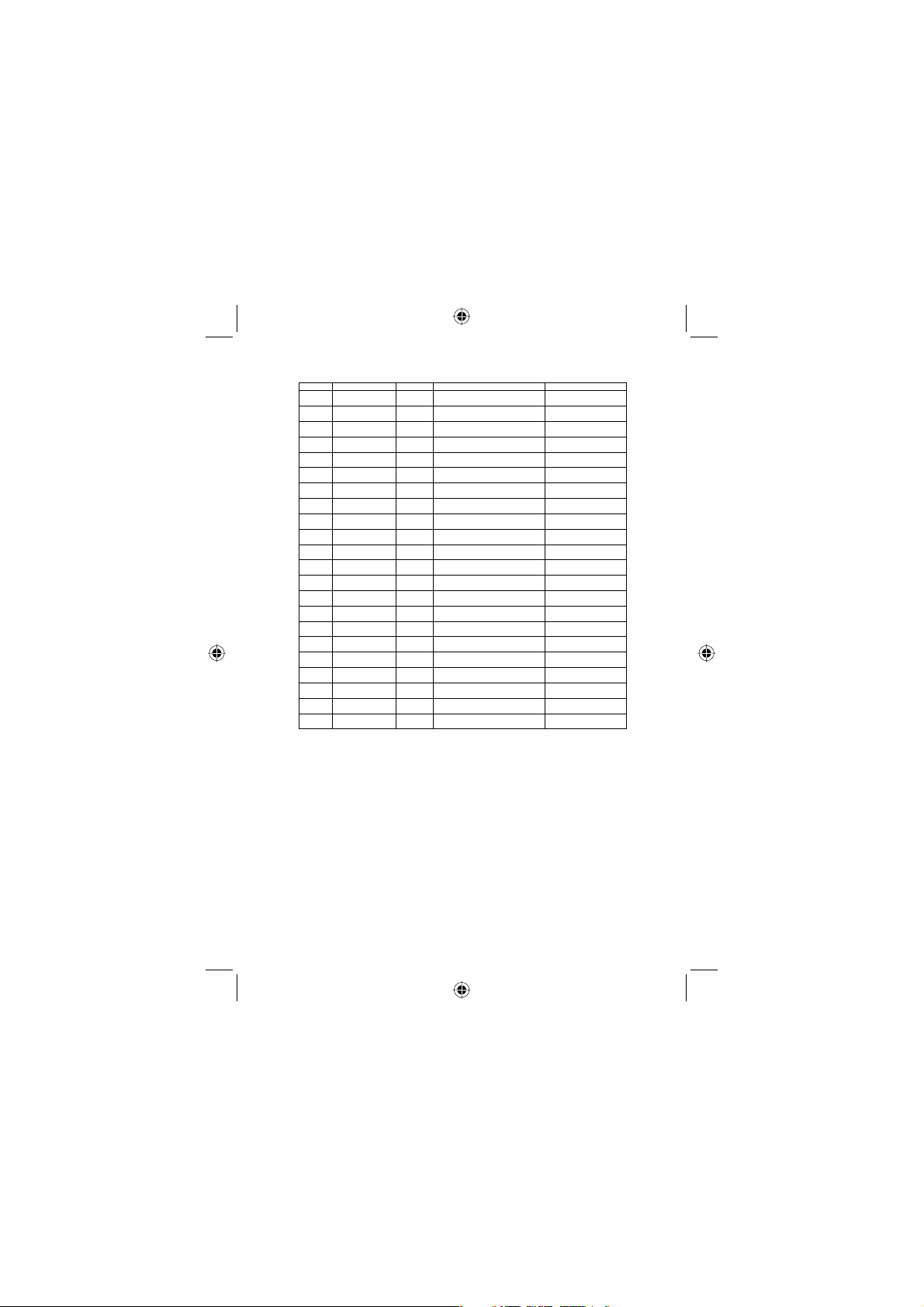
International Channel Frequencies
CH No. RX Freq TX F req Status Full Name 16 Char Name
65 160.8750
156.2750
66 160.9250
156.3250
67 156.3750
156.3750
68 156.4250
156.4250
69 156.4750
156.4750
70 156.5250
71 156.5750
156.5750
72 156.6250
156.6250
73 156.6750
156.6750
74 156.7250
156.7250
77 156.8750
156.8750
78 161.5750
156.9250
79 161.5750
156.9750
80 161.6250
157.0250
81 161.6750
157.0750
82 161.7250
157.1250
83 161.7750
157.1750
84 161.8250
157.2250
85 161.8750
157.2750
86 161.9250
157.3250
87 161.9750
157.3750
88 162.0250
157.4250
Duplex MARINE OPERATOR MARINE OPERATOR
Duplex MARINE OPERATOR MARINE OPERATOR
Simplex BRIDGE TO BRIDGE BRIDGE TO BRIDGE
Simplex NON COMMERCIAL NON COMMERCIAL
Simplex NON COMMERCIAL NON COMMERCIAL
Receive
Inhibit
DIGITAL SELECTIVE CALLING DSC RECEIVE ONLY
Only
Simplex NON COMMERCIAL NON COMMERCIAL
Simplex NON COMMERCIAL NON COMMERCIAL
Simplex PORT OPERATION PORT OPERATION
Simplex PORT OPERATION PORT OPERATION
Simplex PORT OPERATION (SHIP-SHIP) PORT OPERATION
Duplex PORT OPERATION PORT OPERATION
Duplex PORT OPERATION PORT OPERATION
Duplex PORT OPERATION PORT OPERATION
Duplex PORT OPERATION PORT OPERATION
Duplex PORT OPERATION PORT OPERATION
Duplex PORT OPERATION PORT OPERATION
Duplex MARINE OPERATOR MARINE OPERATOR
Duplex MARINE OPERATOR MARINE OPERATOR
Duplex MARINE OPERATOR MARINE OPERATOR
Duplex MARINE OPERATOR MARINE OPERATOR
Duplex MARINE OPERATOR MARINE OPERATOR
45West Marine VHF150 Radio Owner’s Manual
Page 46
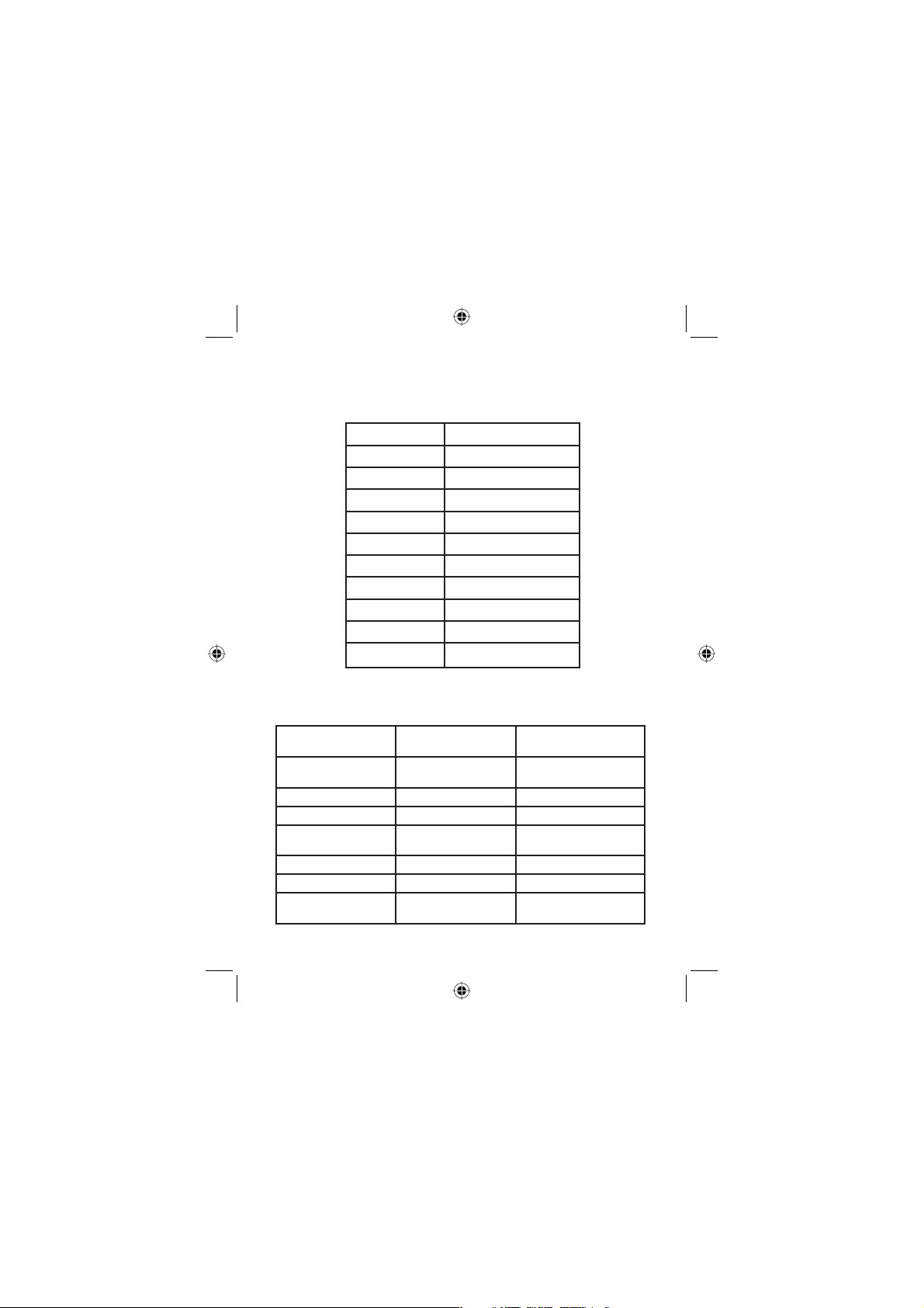
NOAA Weather
Channels and Frequencies
Channel RX Frequency
WX01 162.5500
WX02 162.4000
WX03 162.4750
WX04 162.4250
WX05 162.4500
WX06 162.5000
WX07 162.5250
WX08 161.6500
WX09 161.7750
WX10 163.2750
NOAA Weather
SAME Event Codes
Standard Code
Received
ADR ADMINISTRATIVE
AVA AVALANCHE WATCH AVALANCHE WATCH
AVW AVALANCHE WARNING AVALANCHE WARN
BHW BIOLOGICAL HAZARD
BWW BOIL WATER WARNING BOIL WATER WARN
BZW BLIZZARD WARNING BLIZZARD WARNING
CAE CHILD ABDUCTION
Event Code
(Scrolling Name)
MESSAGE
WARNING
EMERGENCY
Display
(16 Character Name)
ADMIN MESSAGE
BIOLOGICAL WARN
CHILD EMERGENCY
46
West Marine VHF150 Radio Owner’s Manual
Page 47
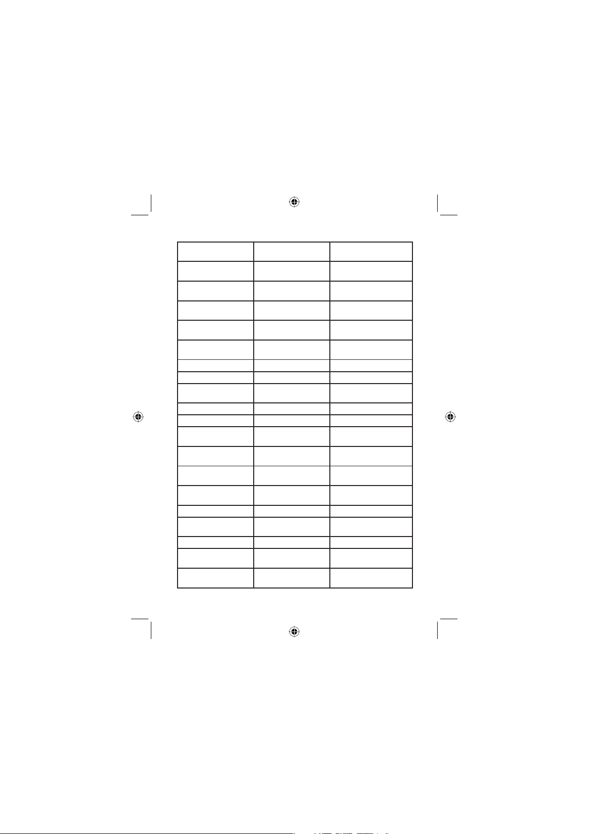
Standard Code
Received
CDW CIVIL DANGER
CEM CIVIL EMERGENCY
CFA COASTAL FLOOD
CFW COASTAL FLOOD
CHW CHEMICAL HAZARD
DBA DAM WATCH DAM BREAK WATCH
DBW DAM BREAK WARNING DAM BREAK WARN
DEW CONTAGIOUS DESEASE
DMO PRACTICE/DEMO SYSTEM DEMO
DSW DUST STORM WARNING DUST STORM WARN
EAN EMERGENCY ACTION
EAT EMERGENCY ACTION
EQW EARTHQUAKE
EVI IMMEDIATE EVACUA-
EVA EVACUATION WATCH EVACUATION
FCW FOOD CONTAMINATION
FFA FLASH FLOOD WATCH FLASH FLOOD WARN
FFS FLASH FLOOD
FFW FLASH FLOOD
Event Code
(Scrolling Name)
WARNING
MESSAGE
WATCH
WARNING
WARNING
WARNING
NOTIFICATION
TERMINATION
WARNING
TION
WARNING
STATEMENT
WARNING
Display
(16 Character Name)
CIVIL DANGER
CIVIL EMERGENCY
COASTAL FLOOD
COASTAL FLOOD
CHEMICAL HAZARD
CONTAGIOUS WARN
EMERGENCY NOTIFY
EMERGENCY END
EARTHQUAKE WARN
IMMED EVACUTATION
FOOD CONTAMIN
FLASH FLOOD WARN
FLASH FLOOD WARN
47West Marine VHF150 Radio Owner’s Manual
Page 48
Standard Code
Received
FLA FLOOD WATCH FLOOD WATCH
FLS FLOOD STATEMENT FLOOD STATEMENT
FLW FLOOD WARNING FLOOD WARNING
FRW FIRE WARNING FIRE WARNING
FSW FLASH FREEZE
FZW FREEZE WARNING FREEZE WARNING
HLS HURRICANE STATE-
HMW HAZARDOUS MATERIAL
HUW HURRICANE WATCH HURRICANE WATCH
HWA HIGH WIND WATCH HIGH WIND WATCH
HWW HIGH WIND WARNING HIGH WIND WARN
IBW INDUSTRIAL FIRE
IFW INDUCTRAL FIRE
LAE LOCAL AREA
LEW LAW ENFORCMENT
LSW LAD SLIDE WARNING LAND SLIDE WARN
NAT NATIONAL AUDIABLE
NIC NATIONAL
NMN NETWORK
Event Code
(Scrolling Name)
WARNING
MENT
WARNING
WARNING
WARNING
EMERGENCY
WARNING
TEST
INFORMATION CENTER
NOTIFICATION
MESSAGE
Display
(16 Character Name)
FLASH FREEZE
HURRICANE
HAZARDOUS WARN
INDUSTRIAL FIRE
INDUSTRIAL FIRE
LOCAL EMERGENCY
LAW ENFORCE WARN
NATIONAL AUDIBLE
NATIONAL INFORM
NETWORK MESSAGE
48
West Marine VHF150 Radio Owner’s Manual
Page 49
Standard Code
Received
NPT NATIONAL PERIODIC
NST NATIONAL SILENT TEST NATIONAL SILENT
NUW NUCLEAR POWER
POS POWER OUTAGE
RHW RADIOLOGICAL HAZARD RADIOLOGICAL
RMT REQUIRED MONTHY
RWT REQUIRED WEEKLY
SMW SPECIAL MARINE
SPS SPECIAL WEATHER
SPW SHELTER IN-PLACE
SVA SEVERE
SVR SEVERE
SVS SEVERE WEATHER
TOA TORNADO WATCH TORNADO WATCH
TOE 911 TELEPHONE
TOR TORNADO WARNING TORNADO WARN
TRA TROPICAL STORM
Event Code
(Scrolling Name)
TEST
PLANT WARNING
ADVISORY
TEST
TEST
WARNING
STATEMENT
WARNING
THUNDERSTORM
WATCH
THUNDERSTORM
WARNING
STATEMENT
OUTAGE EMERGENCY
WATCH
Display
(16 Character Name)
NATIONAL PERIODIC
NUCLEAR WARNING
POWER OUTAGE ADV
REQ MONTHLY TEST
REQ WEEKLY TEST
SPECIAL MRN WARN
SPECIAL WEATHER
SHELTER IN-PLACE
THUNDERSTORM
THUNDERSTORM
SEVERE WEATHER
911 OUTAGE
TROPIC STORM
49West Marine VHF150 Radio Owner’s Manual
Page 50
Standard Code
Received
TRW TROPICAL STORM
TSA TSUNAMI WATCH TSUNAMI WATCH
TSW TSUNAMI WARNING TSUNAMI WARNING
VOW VOLCANO WARNING VOLCANO WARNING
WFW WILD FIRE WARNING WILD FIRE WARN
WFA WILD FIRE WATCH WILD FIRE WATCH
WSA WINTER STORM WATCH WINTER STORM
WSW WINTER STORM
* * A UNRECOGNIZED
* * E UNRECOGNIZED
* * S UNRECOGNIZED
* * W UNRECOGNIZED
TXB TRANSMITTER BACKUPONNo event code shown
TXF TRANSMITTER CARRIERONNo event code shown
Event Code
(Scrolling Name)
WARNING
WARNING
WATCH
EMERGENCY
STATEMENT
WARNING
Display
(16 Character Name)
TROPIC STORM
WINTER STORM
UNRECOGNIZED
UNRECOGNIZED
UNRECOGNIZED
UNRECOGNIZED
TXO TRANSMITTER CARRIER
TXP TRANSMITTER PRIMARYONNo event code shown
50
OFF
West Marine VHF150 Radio Owner’s Manual
No event code shown
Page 51

WARRANTOR: WEST MARINE AMERICA CORPORATION (“West Marine”)
ELEMENTS OF WARRANTY: West Marine warrants, for three years, to the
original retail owner, this West Marine Product to be free from defects in materials and craftsmanship with only the limitations or exclusions set out below.
WARRANTY DURATION: This warranty to the original user shall terminate
and be of no further effect 36 months after the date of original retail sale. The
warranty is invalid if the Product is (A) damaged or not maintained as reasonable or necessary, (B) modifi ed, altered, or used as part of any conversion kits,
subassemblies, or any confi gurations not sold by West Marine,
(C) improperly installed, (D) serviced or repaired by someone other than an
authorized West Marine service center for a defect or malfunction covered by
this warranty, (E) used in any conjunction with equipment or parts or as part of
any system not manufactured by West Marine, or (F) installed or programmed
by anyone other than as detailed by the Operating Guide for this product.
STATEMENT OF REMEDY: In the event that the product does not conform
to this warranty at any time while this warranty is in effect, warrantor will repair the defect and return it to you without charge for parts, service, or any
other cost (except shipping and handling) incurred by warrantor or its representatives in connection with the performance of this warranty. THE LIMITED
WARRANTY SET FORTH ABOVE IS THE SOLE AND ENTIRE WARRANTY
PERTAINING TO THE PRODUCT AND IS IN LIEU OF AND EXCLUDES ALL
OTHER WARRANTIES OF ANY NATURE WHATSOEVER, WHETHER EXPRESS, IMPLIED OR ARISING BY OPERATION OF LAW, INCLUDING, BUT
NOT LIMITED TO ANY IMPLIED WARRANTIES OF MERCHANTABILITY OR
FITNESS FOR A PARTICULAR PURPOSE. THIS WARRANTY DOES NOT
COVER OR PROVIDE FOR THE REIMBURSEMENT OR PAYMENT OF INCIDENTAL OR CONSEQUENTIAL DAMAGES. Some states do not allow this
exclusion or limitation of incidental or consequential damages so the above
limitation or exclusion may not apply to you.
LEGAL REMEDIES: This warranty gives you specifi c legal rights, and you
may also have other rights which vary from state to state. This warranty is void
outside the United States of America.
PROCEDURE FOR OBTAINING PERFORMANCE OF WARRANTY: If, after
following the instructions in this Operating Guide you are certain that the Product is defective, pack the Product carefully (preferably in its original packaging). Include evidence of original purchase and a note describing the defect
that has caused you to return it. The Product should be shipped freight prepaid, by traceable means, or delivered, to warrantor at:
West Marine Electronic Repair Center
2395 Bert Court
Hollister, CA 95023
You can contact us at (831) 761-4205
51West Marine VHF150 Radio Owner’s Manual
Page 52

OUTSIDE
BACK COVER
VHF 150
52
West Marine VHF150 Radio Owner’s Manual
 Loading...