

Page 1

Aniden
MC 790
MARINE RADIOTELEPHONE
OWNER’S MANUAL
Page 2

UNIDEN MC790
The UNIDEN MC790 VHP marine radio
transceiver has been designed to give you
a rugged reliable instrument that will pro
vide you with years of trouble-free service.
You are encouraged to thoroughly read
this manual to acquaint yourself with the
characteristics and operation of your tran
sceiver so that you can contribute to the
longevity of your investment.
With proper care and maintenance, your
UNIDEN MC790 will outlast your present
vessel and serve you well on board several
more. The full features and ilexibilitv de
signed into this quality transceiver will
prevent it from becoming obsolete regard
less of changes in craft or geographic
locations. The unit may be mounted in
any number of convenient locations by
utilizing the universal mounting bracket.
The UNIDEN MC790 is of all solid state
design with conservatively rated rugged
componepts and materials compatible
with the marine environment. The trans
ceiver utilizes a number of gaskets, sealing
rings,, waterproof membranes, and other
sealants to effect a splash proof housing
for protection of the electronics.
INSTALLATION
CAUTION: The iVlC790 will operate only with nominal
battery systems.
'2 volt negative ground
It is important to carefully determine the
most suitable location for your MC790 on
your vessel. Electrical, mechanical, and
environmental considerations must all be
taken into account. You must select the
optimum relationship among these con
siderations.
Keep in mind the flexibility designed into
the fVlC790 so that you can most conveni
ently use your radio. Features which
should be considered are;
n
], Universal mounting bracket may be
installed on either top or bottom of
shelf, bulkhead, or overhead mount
ing.
2. The microphone connector faces for
ward allowing convenient in-dash or
"built-in" installations.
3. The front panel can be fully reversed ro
provide for optimum viewing and
operating for any mounting position.
‘f. The REMOTE speaker jack may be
used with an auxiliary speaker.
All connections are "plug-in" type for
easy removal of the radio.
I I
Page 3

A variety of antennas is available from a
number of quality suppliers. It is recom
mended you draw upon the advice of
your Marine Dealer in determining a
suitable antenna for your vessel and
range, requirements.
CHOOSING A tOCATfON
The general rules, for antennas are: The
more gain the greker the range and, the
higher above the water line the greater
the range. Antennas should be located so
as not to be in proximity to metal olyccts.
Antennas should not have exccs.sively
long coaxial feed cables.
Some of the more important external fac
tors to consider in selecting the location
of your MC790 are:
1. Select a location that is free from spray
and splash.
2. Keep the battery leads as short as pos
sible. Connection directly to the
battery is most desirable. If direct
connection cannot be made with the
supplied ^power lead, any extension
should be made with #10 AWG wire.
Long extensions should use larger
wire. '
3. Keep the antenna lead as short as pos
sible. Long antenna leads cati cause
substantial loss of performance for
both receiving and transmitting,
4. Locate your antenna as high as possi
ble and clear from metal objects. The
reliable range of coverage is a direct
function of antenna height.
5. Select a location that does not allow
the radio to be subjected to direct sun
light (including that coming through
windows).
I
7, Select a location well away from the
ship's compass. Auxiliary speakers also
should be located away from the com
pass.
After you have carefully considereo the
various factors affecting your choice of
location, position the radio (witii the
bracket, microphone, power plug,
antenna plug and any auxiliary plugs
installed) into the selected location to
assure, there is no interference witf? sur
rounding items. Mark the location of the
mounting bracket.
Remove the bracket from the radio and
use it as a template lo mark the hrjie.s to
be drilled for the moutiting iiardware.
Drill the holes and mount the bracket
with hardware compatible with the mate
rial of the mounting surface. Install the
power cable (red ly -t-, black is —),
antenna and all other auxiliary cables and
accessories.
Install the radio into the mounting
bracket and connect all cables and acces
sories to the appcopriate jacks and
connectors.
6. Select a location that allows free air
flow around the heat sink on the rear
of the radio.
Page 4
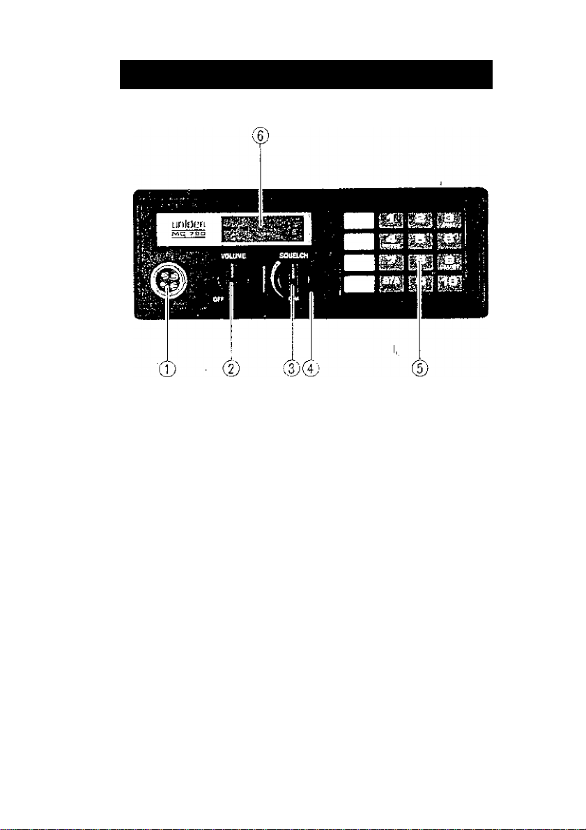
C0MT1I015 AND INDICATORS
(V) Microphone Connector , , . Plug
your Microphone here.
(2.1 ON/OFF VOLUME Knob . . .
Turns power on snd adjusts volume le
vel. ■
c
® SQUELCH Knob . . . Used to sil
ence the backoround noise when no
signal is being received. Turn the knob
just past the point where background
noise siHps.
vi;' DIM Control . . . Adjusts the brigh
tness of both LCD and the keyboard
backlighting for night operation.
Key Bo.nrd . . . Selects the desired
channel, LCD display shows CH-1
through CH-88, Forchannels 1 through
9, first you must depress "0'’then the de
sired channel number. Ifyou attempt to
enter CH, 76 and channels other
than VHF marine channels, which are
Ch. 29 - 59, and 89 - 99, the letter ”E"
will flash in the LCD display and also
"70" will flash when Ch. 70 is selected
for transmit on international channels.
To continue normal use of the radio,
make a proper channel selection,
® LCD . . . Provides indication of chan
nel and function even in brightest sun
light.
Page 5

® REMOTE Speaker Connector
... If you desired to use another
speaker in addition to the one in the un
it, 3 four oreighr ohm speaker equipped
with a miniature phone plug may Pe
connected C0| this jack.
@ DC Power Connector . . . Battery
connections are to be made with the
cable supplied to mate with this con
nector. Remember, red is -r, black is —.
The power cord is equipped with a fuse
to protect the radio. Use only a Six (6)
AMPERE fast blow fuse for replacement.
@ ANT Connector . . . This connec
tor is for connection of the antenna. A
type PL259 connector is required to
■ make proper connection.
Note: Ttie radio must he connected i;j a
power-..source for' the rrii'merry to fun¡ hurí
properly. Remember not-to disconnect tfte
power cable, or you will lose the memory.
However, when this unit is not going tr> be
used for a long period of time, be sure to
disconnect the power cable for safety be
cause the current of less than 1 mA is fed ior
memory back-up even after the radio is
OFF. [But in this case, you will lose the
memory.)
Page 6

CARE AND MAINTENANCE
Your MC790 is a precision piece elec
tronic equipment and you should treat it
accordingly. Due to the rugged design,
very little maintenance is required,
however, a fe\i^ precautions should be
observed.
If your radio has been accidentally subject
ed to splay or splash you should immediate
ly wipe it down with a soft doth dampened
with fresh water.
If the antenna has been damaged, you
should not transmit except in case of
emergency. A defective antenna may
cause damage to your radio.
M
fi
Page 7

SCAN This key iurns on the Memory Scan and gives you "SCAN" on LCD. ¡; the
'----------^ starts its operation. While rt is on, the second digit of the channel nurvrper
----------
' squelch is in operation and Scan Memory Channels are programmed. Scan
shows movement indicating that the Scan is on.
When the radio receives a signal on a programmed channel -while Mc-nory
Scan is on, and squelch opens, it indicates its channel nianbcr and stay, on
that channei. When the signal is gone, squelch closes and Memory Scan is
reactivated.
MAfJUAr] This key is used to check Memory Scan or when ail the memory scan is
I deleted, it is also used when "O" is flashing by mispressing the scan key
^ with no channel numper programmed in memory scan. If you press this
key in a normal operation, it shows each channel number programmed in
Memory Scan. '
9
USA/itJT
T e
S7AÌ
This key gives you international channels or USA channels with an indica
tion of "INT" or "USA" on the display. When the radio is activated,
international channels are automatically available and by pressing the key,
it goes to USA channels.
This key gives you instant access to cnannel 16 and
on LCD when you p.^ess it.
This key gives you instant access to channei 87A and "Si''will be indicated on
LCD when you press it. If channel S7A is selected Irom keyboard while op
erating U,S.A, channels, LCD WILL FLASH "u".
16" will be indicated
enter ] This is the key to turn on the Memory Scan Channel. Select the channei
----------
DELETE
L3
you wish to program, then press the ENTER Key. JMEM" is indicated on
^ the left hand of the channel number to indicate that the program is com
pleted.
This key deletes the programmed Memory Scan Channeiis). When this key
is pressed, the lowest numbered channel in the Memory Scan is.indicated
and deleted. If you keep pressing it. the next lowest channel number is
indicated for deletion. "0" flashes when all the memory scan channels are
deleted. ' ;
These keys arc used to program ctiannci numbers. The last numljcr you
press becomes the first digit, and if the second digit is not programmed
within 10 seconds after the first one. it returns to che previous channel.
When the selected channel number does not exist, "£" flashes.
rin
By pressing this key, "DUAL" is indicated on the display. Everyone and a half
seconds, it monitors CHI 6. If the receiver hears a signal on CH 16. it locks onto
that channel. When the signal stops, it returns to monitoring CHIP r-vety
one and a half seconds. "DUAL" can be operated along with Memory Scan.
By pressing the "DUAL" key, it can be cancelled.
By pressing this key, the power out-put can be changed to 1W and it will be
indicated on LCD. By pressing this key again, the power out-put recur.ns to
25W and the indication on LCD will be turned off. .
DUAL
tw/;sw
3
a
NOTE:
The MC790 has a self-check function to indicate .malfunctions due to overly high
incoming noise levels and sudden, drastic changes of power voltage levels when the
unit is on. This self-check will illuminate all segments of the LCD when triggered. If
this should occur, turn unit off. then back on to reset the microprocessor chip. The
programmed functions will not be erased as long as the Back-up Battery, is functioning.
Please read the Owner's Manual carefully before operating your unit.
Page 8

REVERSING THE I^NT
is) carefully replace cover CA0IWET BUT ON BOTTOM OF RADIO INSERT UNDER PRQNT
PANEL FIRST AND THEN LOWER AT REAR OF RADIO
[91 T URN RADIO OVER AND reconnect a KE R W1 Rf t TAOS
UO} REPOSITION speaker CABINET On TOP OF RADIO AND REPLACE FOUR SCREWS TO SECUf’';.
THE HOUSING. .
(1 Tj RETEGHTEN FOUR appearance COVER SCREWS,
Page 9

.Vs.l.
Interference from the impulse noise gen
erated by the electrical systems of engines
is sometimes a problem with radios. The
MC790 has been designed to be
essentially impervious to ignition impulse
noise and alternator noise. However, in
some installations it may be necessary to
take measures to further reduce the effect
of noi.se inlerfcrencc. All DC ban cry
wires, antenna lead, and accessory cables
should be routed away from the engine
and engine compartment and from power
cabling carrying particularly high currents.
In severe cases of impulse noise interfer
ence. it may be necessary to install a noise
suppression kit that is available from your
Marine Dealer,
■ r
■ T^ I
Page 10

VHF nU MARINE BADIOTELEPHO
CHANNELS AND FUNCnONS
^ laS^. CHANNELS}
CHANNEL
DFSÍGN
01
02
03
04
□5
06 156.300
07 156 3 SO
Gli 1 S6 -UK)
09
10
1 1
12
13 150,650
14
!S -
16 156,000 156 800
r7
re
19
20
21- IS7.050
2Ì 157 ISO
?4
2^
?i> 147.3UÜ
21
2fi ,
60
61 rsóovs
62
63
Ó4
65 154.275
66
6?
6fl
6V
70
71
72
73 156,675
74
77
7ÍJ
79
80
8f
82
S3 157,175 157.175
84
05
Só
37
88
FFIEQUENCY (MHi)
SHIP SHORE
154,050
156,100 156,100
156,150 156.150
156,200
156250 (50,250
3 56,-150
156.500 3 56.500 ' Con'l
156.550
156.600 156 600
156.700
(56.850 156,850 • SiiHr CuriKyJ
156,900 1 56.900
156.950
157,000
157JOO
157 200
167.250
15 7.350 16 1.950
157,400 142.000
156 025
156.125
156.175 156,175
156,225
154*325
156 J75
(56,425
.156,475 156.475
156,525 156.525 ; Non Cpm'l
156,575
I44 42S
156.725 1S6.725
156,875
154.^25 1 56.925 Nori Con’l'I
156 975
157.025 IS7.025
157 075 157,075 . Coast GuitfP
157.125
157,275 f6L825
157.275 ló(.S?5
157.325 161,925 . PuDlic Corresp.
157.375
157.425 162.025 1 Corri']
j
1 TRAFFIC TO SHIP
154.050 VTS
! Port Ops i Yes
¡ Fori Ops
I Pori Ops
156.200
156 300
I5i* V O
J'.6 400 t < nm 1
156 4 50 : Coril'l ^ Mon Corn'l
1 56,950
157.3 00 ; CoasT Guare
161 USO J 'ul )liL C. Lli f i"'g )
14 I.‘/U11
156.025
156.075
156.125
156.225
156,275
156.325
156 .Í75 ; Corn']
156.425
156.5 75
156.675
156.675
156.875
1 56.975
157.125
161.975 . Putific Corresp . No
I
' S.iirty
' { inn'l
156.550
• Pon ops • Y<-
156.650 ' Niivig^HionaJ
156,700
156.7S0 • Enviironmi'nt;vJ
: Corn'!
: Com'l
161.600
157.053 ! Co^st Gliiircl
157 150 C0.1S1 Guaro
161 800 Tiitiln' Corrrsp
I
; Po.'I Ops
i Fort Ops
! JVOn CojTi'f
i Non Com'l
j Non Com'l
; pp.'i ops
! Pon Ops
; Port Ops '
■ Com 1
; US Gov Only
¡ Coast Guarii
! TYPE i SHIP
Com I
POf! Ops Ves
S.ifrty Chilling
Fori; Ops
, J’lrhJn, Ccrrrsp
; FutjIrC Corresp
: FuPJic Corresp
Non Corn'l
Com'l
; PgPiJC Corresp : N0
■ PuOiJC Corresp • No
! SHJP
■ TO SHORE
■ ! Yes
. ves • Yes
■ Yc.S
Ves
Yc^ ' 4Jt, ' C0,1',E f.itj.ii'iJ
Vi’'.
Yi“.
Yri
Ves 1 Ves
Ves
; Ves
¡TX Only
Vr%
Yt's
Yes
Ves Ves
1 Ves Yes
' Yes ; Ves
• Ves
Ví-S
. Nn
TJm ■ Ti-.
N,P Yr-.
No
No i Yes
i Ves Vos
1
i Ves f No
! Ves
: Ves
: Yes
: Yes
: Yes i NO i Fish
¡ Yes
: Yes
■ Ves
Yc>
Ves
^ Ves : Yes
• Yes
. Yes i Ves
Ves
. No
; Ves NO
■ Ye',
: Yes - .
1 Ves ■ ‘
' Yr'.
1 N<.>
j Yes
Yes
' Yes
. Ves
i
‘ PX Ori?v
’ ¥e\
• ¥e^
■ vos
• Yes • CoasT Giiiarri
! Yes
Vr-,
; Yes ! 8usy Tel
1
1
j
! Vo',
F Ves
i Ves . FisP
■ Yes Fish
^ Ves
i Ves
i ''‘1^
I Ves
1 i Vis Busy Tel,
. Ves
: Busy TcJ.
i No • Fish
[
Yes
No
1
Ves i run
Ves Coast Guard
' Busy Tel.
: Busy Tel,
Ves Busy Tel.
PERMAHE
SCAN 1.1S
fjsn
Envjrormu'rii
. Coasi Guikfj.i
, Coasi Ggarrl
ilirsy 1(1
J]ij%y h'l
iJuiy li.'l
FisP
f CoasL Guard
Busy Tel.
Page 11

VHF FM MARINE RADIOTEtEPHONE
CHANNELS AND FUNCTIONS
(INTERNATIONAL CHANNEUf
jfHAfJNEL
DESIGN TRAFFIC
o r
02 ISû 100 160.700 ■ Pofi Op5
03 156.150 160.7 50 Pof\ Opj Yes Yes
04
05
ОГз 156 3Ciü
(У/
1)Я 150 4UU \\i, -100 i-tJiUl Vi*i No
09 156.450 156.450 Com'i К NO(T СсшП
10 T56.500 156 500 ,
1 ] 156.550 156.550 Слгп 'I
1^ 1 56.600 156.600 Pori Ops Yci Yes
13
14
Î5 1 56.750 156.750 EnvefOrirncniFlP Yes Yes EnvironmcAiat
16 1 56.800 156 8ÛÛ j CalfinQ Yt:s Yes
1 7
18 r 56.900
19 1 S6.9S0 161,550 . Corn!
20 rS7 OOÛ 161.60Û .
21 Г57.050 161,650 : CoEiSi Guerci Yes Yes
22 157.100 161.700 ' Co^si GuArd Yes Yes
23
21 г 5 7 ?00 16 J 8ПП 1
/fi
27
28 157.400 162.ÛÛÛ ;
60 156 025 160625 :
61 156.075 360.675 !
62
63 156,1 75 160.77S 1
64
65 rS6,275 160,875 '
66 -1 56,325 160.925 ! Pon Ops
bJ [Sü.3;'5
68
69 156.475
70
7 1
7?
73 Г56.675 156.675 ' Port Ops Yes Yes
74
77
7У
79 '■'1S6.97S Î61.575 Com'l
80 157,025 !6Г,625 t Com'l Yes Yes
81
82
83 Г57.175 IÔI.775 '
34
fis Г57.275
S6 fS7,3?5 161,925 i PuDllC Corfosp. ■Mo Yes
87
07A
88
FREQUENCY [MHzJ
SHIP SHORE
I56 0S0 160.650 1 VT5 Vos Yes
] 56.200 160.300 ■ Port Opi y=! Yes
156.250
ГгЛ s 50 160 OMi
156.650 156.650
1 56,700 156,700 .
Г56.850 156,850 Control Yes Yes
Î57.150
Г57 2 5Ü
Г5АЗОО
1 57.'350 161.950 1 PuOric Corfcsp
156.125 160.725 1 i
156.225 160.S2S 1
Г56.425 !
—
Г56.575 156.575 1
156,625 156.625 i Non Com'!
156,725 156.725 1 Pdtc Ops
156.875 Г56.875
.156 925 Г61.525 1
157.075 I6Î.675 r
157.125 16Г,725 Lp5 Gov Only Yes Yes
157.225 161.325 :
157.375 161.975 ; Public Corresp
157.375 157.375 !
Г57.425 162,025
160.000 !
156 300
161.500
161.750 1
I6J Î3',0 !
K. I.'JOO 1
1563/5 ‘
156.475 i
156,525 1
16Г.875 f
^ TYPE
VT5
5i.i 1L's у Y(.'S NO
Com'l
Nivlg? Lionel Yes
PoriL ops
Com'l
PorL Ops
Cfjfljt Guord
r'lJtiPir NPf}
P'lJtjfll. i" £'‘,fJ
f'uPjiK Coifc^p NO Yes
PunPic Corr<bsp
Port Ops
CorriJ
Non Corn'i
Non Cpm'l
Non Com'l
Non Com'l
Port Opi
Non Com'f
CoetsL Gu^rd
Coast Guard
PuPiii Corresp,
Public CorffSp.
Com 1
’
SHIP SHIP PERMANENT
TO SHIP
I
'
res Yes
l'es
Yn',
Yes
Yes Yes
I
Yes Yes
!
Yes ■ Yes
Ves 1 Yes
I
Yes Yes
Yes
i
Yes Yes
I
No Yes Busy TcL
j
NO Yt! Busy TN.
I
i
Yes Yes
I
Yes Yes
Yc-S No
Yci Yes
Yes Yes
Yes
Yes Yes
.
Yes
Yes Yes
E
Yes No
res YC!
Yes
I
I
Yes Yes Coast Guard
Ves Ves Coast Guard
No Yes Busy Tel, 1
No Yes Susy Tef, 1
■ Wo
Yes
TO SHORE 6(,AN UJ6 1
Yes
yi'\
Yes Fish
Yes
Yes
Nir '
Yes
Yes 3iisy Tel.
No Fish
NO Fish ' ■
Y«
Yes 8usy Tel,
, No
EJusy Tel.
FrSPi
Fish
Fish
Susy Tel.
Tci,
Busy Tel, '
1
CAUTION: OPERATION ON CHANNELS 1 5 AND 1 7 HAS BEEN ELECTRONICALLY
RESTRICTED TO LOW POWER TO PROTECT CH. 1 6. THE DISTRESS FREQUENCY.
Page 12

GENERAL
Channels
Frequency Control
Method
Antenna Impedance
Speaker
Microphone
Channel Display
Frequency Stability
Operating Tempera
ture Range
Shock and Vibration
Size
Weight
Controls
Connectors
Frequency Range
Lights and Indicators
Standard Accessories
Supply Voltage •
TRANSMITTER
Power Output
Power Requirement
Modulation
Hum and Noise
Attenuation
Audio Distortion
Spurious Emission
Output Transistor
Protection
Output Pov/er
Stabilization
Transmit 55
Receive 80
PLL synthesizer
50 ohms, nominal '
2.85 inch, 8 ohms
Rugged 600 ohms dynamic element with coiled cord
and plug-in connector
LC.D
±0.001%
± 20‘’C to + 50°C -
Meets or exceeds EIA standards, RS152B and RS204C
7-l/4"W (185m/m) x 9-5/S'l [245m/m] x 2-]/4"H
(58m/mj .
16 kg
On-Off/Voiume, Squelch S Dimmer controls, Key Board
Antenna, microphone, remote speaker. DC power
156 to 158 MHz transmit
156 to 163 MHz receive
Channel Number, , 25W, IW, USA. INT, DUAL,
SCAN, MEM, Backlight Key Board & LCD.
Plug-in microphone, mounting bracket and hardware,
DC power cord, mike hanger, spare fuse, owner's
manual
13,8V DC negative ground :
I
25 or Ì watt [keypad selectable]
25 watts output: 5.0A О Ì3.8V DC
I watt output : 1,0A I5.av DC
FM, ±5 kHz deviation
40 dB
Less than 5% with 3 kHz deviation with 1000 Hz
modulating frequency
-70 dB
Built-in
Built-in automatic level control (ALCj
Page 13

RECEIVER
Sensitivity :
Threshold Squelch : 0.20,iiV/ (EIA method)
Sensitivity
Tight Squelch :
Sensitivity
Spurious Response :
Attenuation
Image Response :
Attenuation
Intermodulation : 65 dB 12 dB SINAO
Attenuation
Adjacent Channel :
Rejection Selectivity :
Audio Output Power : 3.5'watts minimum at 10% distortioln at 1 kHz modula
Power Requirement ' ;
IF Frequencies ' :
Flum and Noise Level :
O.BSiiV for 12 de SINAD
O.SOhV for 20 dB S/N
2.0/iV (EIA method) '
75 dB
75 dB
70 dB (EIA method)
± 7.5 kHz (>'■■ 6 dB down .
± 15 kHz ir 60 dB down
tion and ±3,5 kHz deviation [4 ohm speaker)
0.6A t"'13.8V DC, squelched
1,2A i"' 1 3.8V DC at rated audio output
1st - 21.4 MHz ■
2nd — 455 kHz ■ '
—50 dB [EiA method)
 Loading...