

Page 1
undeiT
MC 610
MARINE RADIOTELEPHONE
OWNER’S MANUAL
Page 2

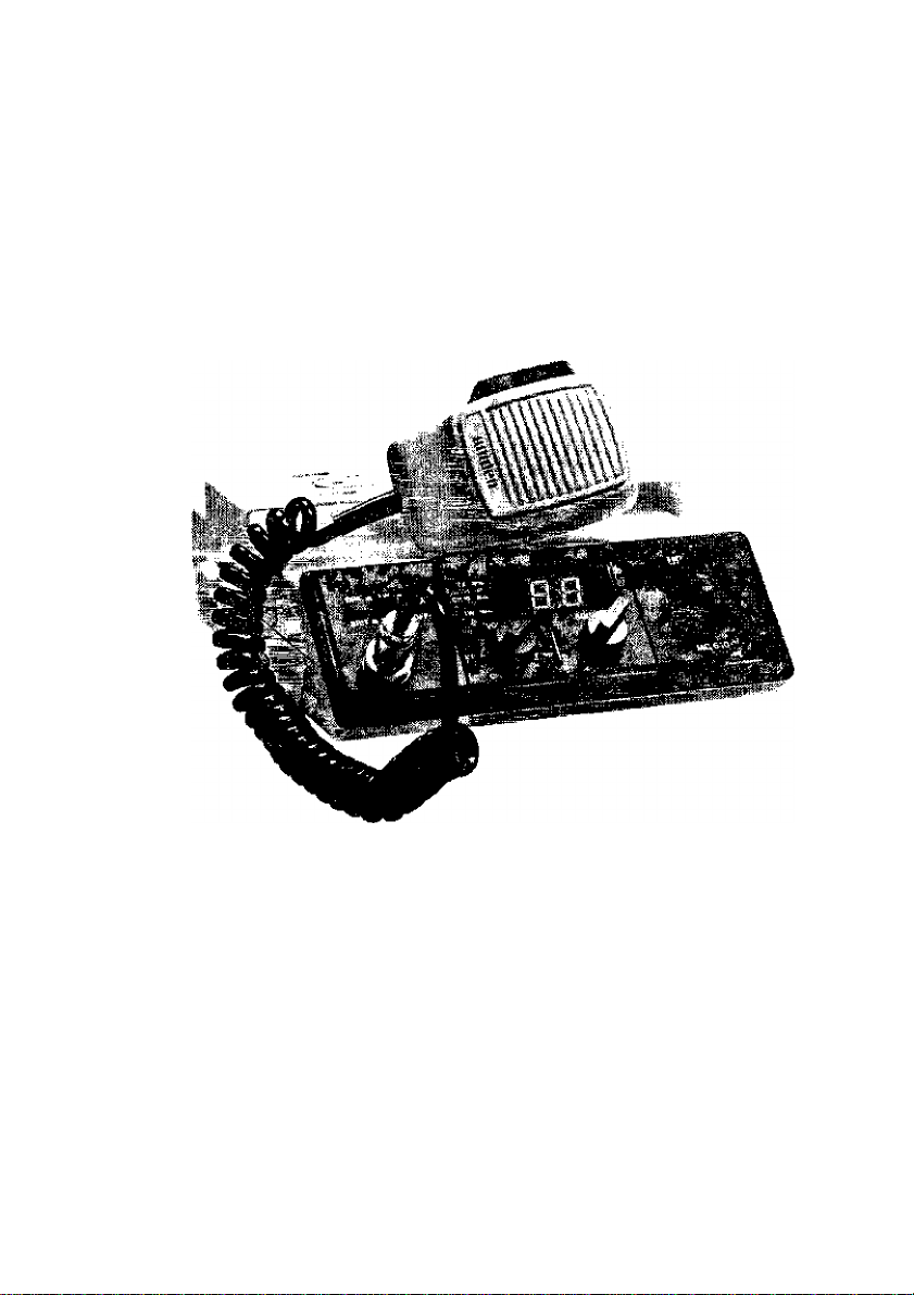
UNIDEN MC610
The UNIDEN MCÓIO VHF marine radio
transceiver has been designed to give you a
rugged reliable instrument that will pro
vide you with years of trouble-free service.
You are encouraged to thoroughly read
this manual to acquaint yourself with the
characteristics and operation of your tran
sceiver so that you can contribute to the
longevity of your investment.
With proper care and maintenance, your
UNIDEN MC610 wilt outlast your present
vessel and serve you well on board several
more. The full features and flexibility de
signed into thisquality transceiver will pre
vent it from becoming obsolete regardless
of changes in craftorgeographic locations.
The unit may be mounted in any number of
convenient locations by utilizing the uni
versal mounting bracket.
The UNIDEN MC610 is of all solid state de
sign with conservatively rated rugged com
ponents and materials compatible with the
marine environment. The transceiver uti
lizes a number of gaskets, sealing rings,
waterproof membranes, and other sea
lants to effect a spiash proof housing for
protection of the electronics.
INSTALLATION
CAUTION: The MC610 will operate only with nominal 12 volt negative ground
battery systems.
It is important to carefully determine the
most suitable location for your MC610 on
yourvessel. Electrical, mechanical, and en
vironmental considerations must all be tak
en into account. You must select the opti
mum relationship among these consider
ations.
Keep in mind the flexibility designed into
the MCÓ10 so that you can most conveni
ently use your radio. Features which should
be considered are;
I. Universal mounting bracket may be in
stalled on either top or bottom of shelf,
bulkhead, or overhead mounting.
2, The microphone connector faces for
ward allowing convenient in-dash or
"built-in" installations,
3, The front panel can be fully reversed to
provide for optimum viewing and op
erating for any mounting position.
4, The REMOTE speaker jack may be used
with an auxiliary speaker.
All connections are "plug-in" type for
easy removal of the radio.
Page 3

ANTENNA CONSIDERATIONS
A variety of antennas is available from a
number of quality suppliers. It is recom
mended you draw upon the advice of your
Marine Dealer in determining a suitable
antenna for your vessel and range require
ments.
CHOOSING A LOCATION
Some of the more important external fac
tors to consider in selecting the location of
your MC610 are:
1. Select a location Is free from spray and
splash.
2. Keep the battery leads as short as possi
ble. Connection directly to the battery is
most desirable, If direct connection can
not be made with the supplied power
lead, any extension should be made
with #J0 AWG wire. Long extensions
should use larger wire,
3. Keep the antenna lead as short as possi
ble. Long antenna leads can cause sub
stantial loss of performance for both re
ceiving and transmitting,
4. Locate your antenna as high as possible
and clear from metal objects. The reli
able range of coverage is a direct func
tion of antenna height.
5. Select a location that does not allow the
radio to be subjected to direct sunlight
(including that coming through win
dows).
The general rules for antennas are; The
more gain the greater the range and, the
higherabove the water line the greater the
range. Antennas should be located so as
not to be in proximity to metal objects. An
tennas should not have excessively long
coaxial feed cables.
7. Select a location well away from the
ship"s compass. Auxiliary speakers also
should be located away from the com
pass.
Afteryou have carefully considered the var
ious factors affecting your choice of loca
tion, position the radio [with the bracket,
microphone, power plug, antenna plug
and any auxiliary plugs installed) into the
selected location to assure, there is no in
terference with surrounding items, Mark
the location of the mounting bracket.
Remove the bracket from the radio and use
it as a template to mark the holes to be
drilled for the mounting hardware. Drill the
holes and mount the bracket with hard
ware compatible with the material of the
mounting surface. Install the power cable
(red is -k, black is—), antenna and all other
auxiliary cables and accessories.
Install the radio into the mounting bracket
and connect all cables and accessories to
the appropriate jacks and connectors.
6. Select a location that allows free air flow
around the heat sink on the rear of the
radio.
Page 4

FRONT PANEL CONTROLS AND INDICATORS
®C6)® (8)® (n)
T-ffV
1 A
®C3) ®
(D Channel Selector . . , Selects the
desired channel. LED display shows 0)
through 88. Ad channels are displayed
by two digits, including “0" on the first
digit.
® Microphone Connector . . . Re
ceptacle for microphone connection.
@ ON/OFF VOLUME . . . Turns
power on and adjust the listening level.
Whenever the power is turned on, the
unit automatically goes to Channel J6.
® SQUELCH . . . Used to silence the
background noise when no signal is be
ing received. Turn the knob just past
the point where background noise
stops.
unneR
(b
@ CHI6 Selector . . . Provides instant
tuning toCH 16 overriding Rotary Chan
nel selector. LED indicator and Channel
display will indicate when unit is on
Channel 16. When you press "OFF", the
channel will go back to the channel
tuned just before you pressed 'CH J6"
The Channel display will go back to that
channel.
TX LED Indicator
the transmit mode.
® CH16 LED Indicator . . . Lights
when CHI6 SELECTOR is activated.
® 1 WATT LED Indicator . . . Shows
when unit is switched to Low power (I
WATT).
. Glows red in
® DIM/BRIT Selector . .
the brightness of the display.
® 1W/25W Selector . . . Controls
transmitter output power. Use the IW
(WATT) position for in-port or short
range communications.
Adjusts
® LED Channei Display
cates channel in use.
COUTfON: When CH87A is used. LED
channel display shows as 87 , 8 (bigger
than 7) and 7 (smaller than 8} by
comparison.
Indi-
Page 5

REAR PANEL CONNECTORS
(D REMOTE Speaker Connec
tor . . . If you want to use another
speaker in addition to the one in the un
it, a four or eight ohm speaker equipped
with a miniature phone plug may be
connected to this jack. To operate, con
nect external speaker (not supplied)
with this phone plug into jack located
on back of unit. Note that both speak
ers built-in and external can be used si
multaneously.
® DC Power Connector . . . Make
the battery connections with the cable
supplied. Remember, red is -1-, black is
—. The power cord is equipped with a
fuse to protect the radio. Use only a 6A
fast blow fuse for replacement. This fuse
is supplied with the unit as an accessory.
® ANT Connector . . . Connect the
antenna here. A type PL259 connector
is required to make proper connection.
Page 6

REVERSING THE FRONT PANEL
(8) CAREFULLY REPLACE COVER CABINET ON BOTTOM OF RADIO. INSERT UNDER
FRONT PANEL FIRST AND THEN LOWER AT REAR OF RADIO.
(9) TURN RADIO OVER AND RECONNECT SPEAKER WIRE LEADS.
(10) REPOSITION SPEAKER CABINET ON TOP OF RADIO AND REPLACE FOUR SCREWS
TO SECURE THE HOUSING.
(II)RETIGHTEN FOUR APPEARANCE COVER SCREWS.
Page 7

CHANNELS AND FUNCTIONS
VHF FM WIARINE RADIOTELEPHONE (INT¥RNATIONAL CHANNELS)
CHANNEL
DESrGN
Oi 156,050 160,650 VTS
02
03 156,150 T60 750 Port Ops
04
05 156,250 160,850
06 156.300 156,300 Safety
07 156.350 160 950 Cojn'J
08 156.400
09
10 156.500
] 1
12
13 156,650 156,650 Navigatlonaf
14
T5 156.750 156,750
16 156.800
17
18
19
20
21
22 157.100 161 700
23 157.150
24
25 157.250
26
27
28 157.400 162,000
60 156.025 160,625
61 156.075
62 156.125
63 156.175
64
65 156.275
66
67
68 156,425 156,425 Non Com'i
69
71 156.575
72
73 156,675 156,675
74
77 156.875
78 156,925
79 156975
SO
B1
02
83 157.175 161 775 Coast Guard
84
85 157275
86
87
87A
88
FREQUENCY fMHi)
SHIP
156,100 160,700
156,200 160,800 Port Ops
156.450 156 450
156.550 156 550 Com'l Ves
156.600 156,600 Port Ops
156,700 156,700 Port Ops
156.850 156,050 Slate Control
156.900 161,500 Com'l
156.950 16?,550 Com!
157.000 161,600 Port Ops
157.050 161,650 Coast Guard
157.200 161 800
157.300 161,900 Public Corresp.
157.350 161,950
156.225 160,025
156.325 160,925 Port Ops Yes
156.375 156,375 Com'l
156,475 156 475 Non Com'i
156.625 156.625 Non Com'i
TS6 725
157.025 161,625 Com'l
157.075 161,675 Coast Guard
157.125 161,725 US Gov Only
157,225 161 825
157325 161,925 Public Corresp. No
157375 161.975 Public Corresp.
157375 157,375
157,425
SHORE
156 400
156 500
156 800 Safety Calling Yes
161 750 Coast Guard Yes
161 850 PuOlic Corresp,
160675
160725
160 775
160,875 Port Ops
156 575
156 725
156875
161.525
161.575 Com'l Yes
161 875 Public Corresp, No
162.025 Com'l
TYPE
TRAFFIC
Port Opi
VTS Yes Yes
Com'!
Co 111'i S Non Com'l Yes Yes
COJTi'i
Entfjronmentai Yes Yes
Coast Guard
PuPlic Corresp. No
Public Corresp.
Public Corresp, No
Non Com'i
Port ops
Port Ops
Port Ops
Non Com'i
Public Corresp. No Yes Busy Tel.
SHIP
TO SHIP
Ves Yes
Yes Yes
Yes Yes
Yes Yes
Yes No
Ves
Ves No
Yes
Yes Yes
Yes Yes
Yes Yes
Yes Ves
Ves Ves
Yes Yes
Yes Yes
Yes Yes
Yes
No Yes Busy Tef,
No Yes Busy Tef.
No Yes
Yes Yes
Yes No
Yes Yes Fish
Yes Yes Fish
Yes
Yes No Fish
Yes Yes
Yes
Yes No
Yes Yes
Yes Yes
Yes Yes Coast Guard
Yes Yes
Yes Yes Coast Guard
No Yes Susy Tei.
Yes No Busy TeJ.
SHIP
TO SHORE
Yes
Yes
Yes
Yes
Yes
Yes
Ves Busy Tel.
Yes Susy Tei,
Yes
Ves Fish
Yes
Yes
Yes Busy TeJ.
Ves Busy Tel.
PERMANENT
SCAN LIST
Fish
Environmental
Busy Tei.
1
_
CAUTION: OPERATION ON CHANNELS 15 AND 17 HAS BEEN ELECTRONICALLY
RESTRICTED TO LOW POWER TO PROTECT CH. 16, THE DISTRESS FREQUENCY.
Page 8

ENGINE NOISE SUPPRESSION
Interference from the impulse noise gener
ated by the electrical systems of engines is
sometimes a problem with radios. The
MC610 has been designed to be essentially
impervious to ignition impulse noise and al
ternator noise. However, in some install
ations it may be necessary to take measures
to further reduce the effect of noise inter
ference. All DC battery wires, antenna
CARE AND MAINTENANCE
Your MC6I0 is a precision piece of elec
tronic equipment and you should treat it
accordingly. Due to the rugged design,
very little maintenance is required, how
ever, a few precautions should be ob
served.
Ifyou radio has been accidentallysubjected
to spray or splash you should immediately
wipe it down with a soft cloth dampened
with fresh water.
lead, and accessory cables should be rout
ed away from the engine and engine com
partment and from power cabling carrying
particularly high currents.
In severe cases of impulse noise interfer
ence, it may be necessary to install a noise
suppression kit that is available from your
Marine Dealer.
If the antenna has been damaged, you
should not transmit except in case of
emergency. Adefectiveantenna may cause
damage to your radio.
You are urged to arrange for periodic per
formance checks with your Marine dealer.
Page 9

OlAfaiAT
Page 10

TWO YEAR LIMITED WARRANTY
WARRANTOR. SANTRONIC AGENCIES
PTY. LTD. 13 Garema Circuit, Kingsgrove
NSW 2208 ("SANTRONIC"!.
ELEMENTS OF WARRANTY. SAN
TRONIC warrants, for the duration of this
warranty, its UNIDEN Product to be
free from defects in materials and crafts
manship with only the limitation or exclu
sions set out below.
WARRANTY DURATION. ThisWarranty
shall terminate and be of no further effect
Two |2| years after the date of original pur
chase of the Product oral the time the Pro
ducts is (a) damaged or not maintained as
reasonable and necessary, (b) modified, (c)
improperly installed, (d) is repaired by
someone other Warrantor for a defect or
malfunction covered by this Warranty, or
(e) used in a manner or purpose for which
the Product was not intended.
PARTS COVERED. This Warranty covers
all components of the Products.
STATEMENT OF REMEDY. In the event
that the Product does not conform to this
Warrantyat anytime while this Warranty is
effective, Warrantor will repair the defect
and return it to you prepaid, without
charge for parts, service, or any other costs
incurred
by Warrantor or its representatives in con
nection with the performance of this War
ranty. In addition, if the Product contains a
defect or malfunction which is not repaired
after a reasonable number of attempts by
Warrantor to repair the Product, the Pro
duct or defective component will at our dis
cretion, be replacedwithoutcharge, when
the defective product is delivered to the
warrantor at 13 Garema Circuit Kingsgrove
NSW2208 freeand clear of all liensandencumbrances. Please note that while the
Product will be remedied under this War
ranty without charge, THIS WARRANTY
DOES NOT COVER OR PROVIDE FOR THE
REIMBURSEMENT OR PAYMENT OF IN
CIDENTAL OR CONSEQUENTIAL DA
MAGES.
PROCEDURE FOR OBTAINING PER
FORMANCE OF WARRANTY. In the
event that the Product does not conform to
this Warranty, the Product should be
shipped prepaid to Warrantor at 13 Gare
ma Circuits Kingsgrove NSW 2208, THE
ORIGINAL OR COPY OF THE SALES RE
CEIPT OR OTHER VALID EVIDENCE OF
THE DATE OF THE ORIGINAL PURCHASE
MUST ACCOMPANY THIS PRODUCT.
Sanironic t
AGENCIES PTY. LTD.
13 GAREMA CIRCUIT, KINGSGROVE
PHONE 758 1522, TELEX AA73170
P.O. Box 12, Kingsgrove, NSW 2208
BRISBANE; 3/12 RANDALL ST
SLACKS CREEK, OLD 4127
PHONE 07 290 1 188
UTSN0?83ICA(SK) Printed in Taiwan
MELBOURNE: 446-448 BELL ST„
EAST PRESTON VIC 3072
PHONE: (03) 484 0373
PERTH: 23 GEDDES ST.,
BALCATTA WA 602 I
PHONE; (09) 344 3937
 Loading...