

Page 1

®
MC 1020
VHF Marine Radio
Operating Guide
UTZZ01868ZZ
Page 2

Maritime Radio Services Operation
Warning!
This transmitter will operate on channels/ frequencies that
have restricted use in the United States. The channel
assignments include frequencies assigned for exclusive use
of the U.S. Coast Guard, use in Canada, and use in
international waters. Operation in these frequencies without
proper authorization is strictly forbidden. For
frequencies/channels that are currently for use in the U.S.
without an individual license, please contact the FCC Call
Center at 1-888-CALL-FCC.
For individuals requiring a license, such as commercial users, you should
obtain a license application from your nearest FCC field office.
Page 3

Contents
Uniden MC 1020...............................................1
Installation ...................................................2
Choosing a Location ........................................2
Engine Noise Suppression....................................3
Antenna Considerations......................................3
Installing The MC 1020 ......................................3
Controls and Indicators..........................................4
Front Panel ...............................................4
Rear Panel Connectors ......................................5
Multi-Function Keys .........................................7
Operation ....................................................9
Triple Watch...............................................9
Manual Tuning .............................................9
Instant Channel 16/Channel 9 Communications ...................9
Weather Scan ............................................10
US/International/Canadian Channels...........................10
MEM (Entering channel numbers into Memory Scan) ..............10
Memory Scan.............................................11
Public Address ............................................11
Weather Alert .............................................11
Transmitting ..............................................12
Dimming the LCD Display Backlight and the TX Indicator...........12
Optional Accessories ..........................................13
VHF FM Marine RadioTelephone
Channel and Functions
(USA Channels) ..............................................14
VHF FM Marine RadioTelephone
Channel and Functions
(International Channels) ........................................15
VHF FM Marine RadioTelephone
Channel and Functions
(Canadian Channels) ..........................................16
Specifications ................................................17
Page 4

Uniden MC 1020
The Uniden MC 1020 VHF marine radio transceiver has been designed to
give you a rugged, reliable instrument that will provide you with years of
trouble-free service.
With proper care and maintenance, your Uniden MC 1020 will outlast your
present vessel and serve you well on-board several more. The full features
and flexibility designed into this quality transceiver will prevent it from
becoming obsolete regardless of changes in craft or geographic locations.
The technical excellence of the Uniden MC 1020 is demonstrated by the
multiplicity of uses for which it has been found acceptable by the U.S. Federal
Communications Commission. The Uniden MC 1020 is acceptable for
compulsory use on “party boats,” for use on vessels subject to the Great
Lakes Radio Agreement or bridge-to-bridge requirements, for general pleasure
and commercial vessels, and certain land stations in marine service.
The Uniden MC 1020 is of all solid state design with conservatively rated
rugged components and materials compatible with the marine environment.
The transceiver utilizes a number of gaskets, sealing rings, waterproof
membranes, and other sealants to effect a splashproof housing for protection
of the electronics. The unit may be mounted in any number of convenient
locations on your vessel by utilizing the universal mounting bracket.
You are encouraged to thoroughly read the rest of this Operating Guide to
acquaint yourself with the characteristics and operation of your transceiver so
that you can contribute to the longevity of your investment.
Keep your receipt as proof-of-purchase in case warranty service is required.
Features, Specifications, and availability of Optional Accessories are all
subject to change without notice.
1
Page 5

Installation
Caution: The MC 1020 will operate only with nominal 12 volt
negative ground battery systems.
It is important to carefully determine the most suitable location for your
MC 1020 on your vessel. Electrical, mechanical, and environmental
considerations must all be taken into account. You must select the optimum
relationship among these considerations.
Keep in mind the flexibility designed into the MC 1020 so that you can most
conveniently use your radio. Features which should be considered are:
1. The universal mounting bracket may be installed on either the top or
bottom of a shelf, on a bulkhead, or for overhead mounting.
2. The REMOTE speaker jack can be used with an auxiliary speaker.
3. All connections are “plug-in” type for easy removal of the radio.
4. Front fire internal speaker allows convenient in-dash mounting using the
optional bracket.
Choosing a Location
Some important factors to consider in selecting the location for your MC 1020:
1. Select a location that is free from spray and splash.
2. Keep the battery leads as short as possible. Direct connection to the
battery is most desirable. If direct connection cannot be made with the
supplied power lead, any extension should be made with #10 AWG wire.
Long extensions should use larger gauge wire.
3. Keep the antenna lead as short as possible. Long antenna leads can cause
substantial loss of performance for both receiving and transmitting.
4. Locate your antenna as high as possible and clear from metal objects. The
reliable range of coverage is a direct function of antenna height.
5. Select a location that does not allow the radio to be subjected to direct
sunlight (including that coming through windows).
6. Select a location that allows free air flow around the heat sink on the rear
of the radio.
7. Select a location well away from the ship’s compass. Auxiliary speakers
also should be located away from the compass.
2
Page 6

Engine Noise Suppression
Interference from the impulse noise generated by the electrical systems of
engines is sometimes a problem with radios. The MC 1020 has been designed
to be essentially impervious to ignition impulse noise and alternator noise.
However, in some installations it may be necessary to take measures to
further reduce the effect of noise interference. All DC battery wires, antenna
lead, and accessory cables should be routed away from the engine and
engine compartment, and from power cabling carrying particularly high
currents.
In severe cases of impulse noise interference, it may be necessary to install a noise
suppression kit. Contact your Uniden Dealer for more information.
Antenna Considerations
A variety of antennas is available from a number of quality suppliers. It is
recommended you draw upon the advice of your Uniden Dealer in determining
a suitable antenna for your vessel and range requirements.
In general, communication range is increased by using a high-gain antenna
placed as high as possible above the water line. Antennas should be located
away from metal objects. Antennas should not have excessively long coaxial
feed cables.
Installing The MC 1020
After you have carefully considered the various factors affecting your choice of
location, position the radio (with the bracket, microphone, power cord, antenna
and any auxiliary cables installed) into the selected location to assure there is
no interference with the surrounding items. Mark the location of the mounting
bracket. Remove the bracket from the radio and use it as a template to mark
the holes to be drilled for the mounting hardware. Drill the holes and mount the
bracket with hardware compatible with the material of the mounting surface.
Connect the red wire of the supplied power cord to the positive (+) battery
supply. Connect the black wire of the power cord to ground. The power cord is
equipped with a fuse to protect the radio. Use only a Six (6) Ampere fast blow
fuse for replacement. Connect the power cord to the keyed connector on the
power “pigtail” (See page 9).
Connect the antenna and all other auxiliary cables and accessories.
Install the radio in the mounting bracket and connect all cables and
accessories to the appropriate jacks and connectors.
3
Page 7
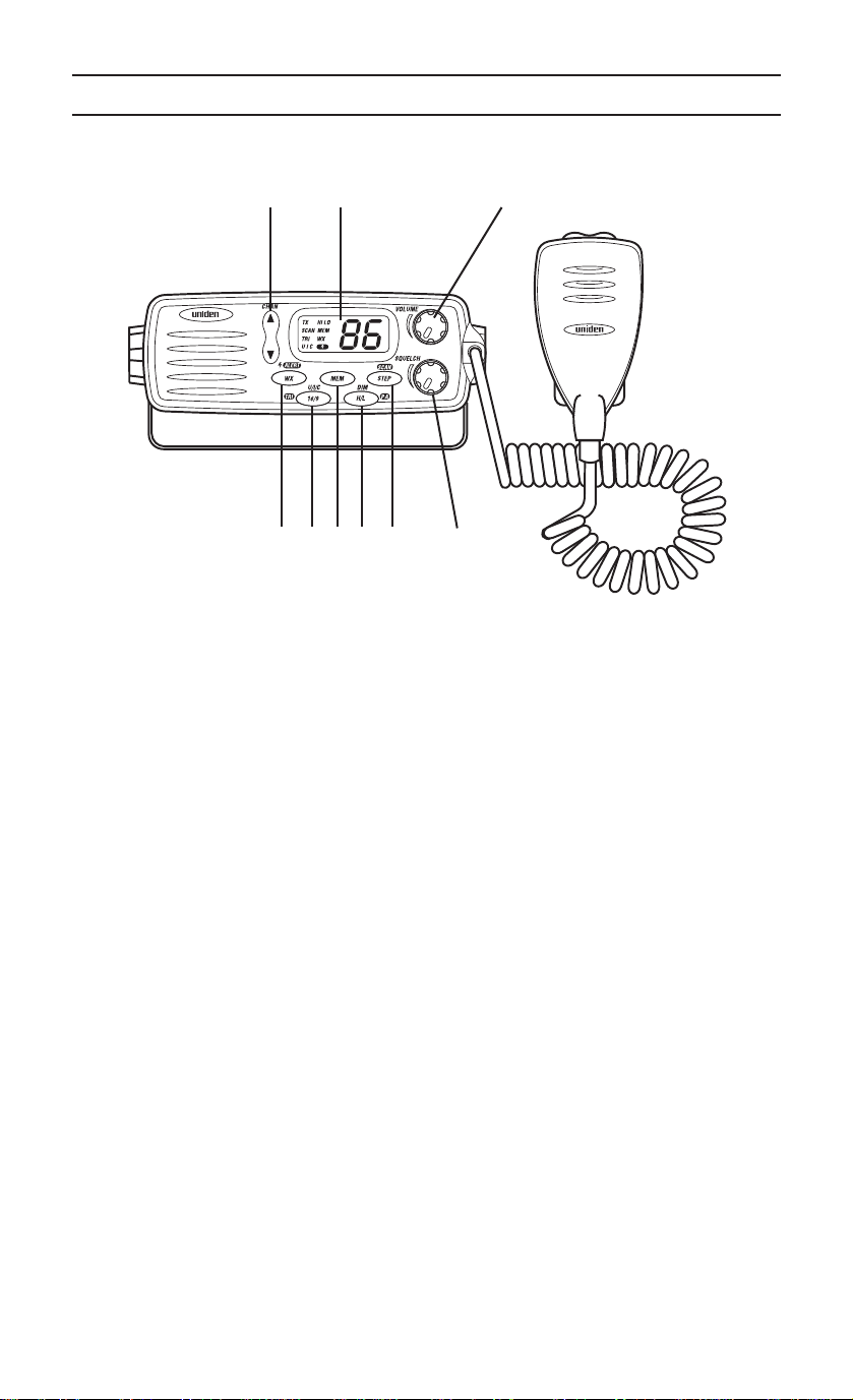
Front Panel
Controls and Indicators
8
91
76 453 2
1. VOLUME (On/Off/Volume) - Turns the MC 1020 On or Off and varies the
audio output.
2. SQUELCH - Eliminates background noise when no signal is being
received.
Note: Items 3 through 7 are Multi-Function keys. Refer to the
“Multi-Function Keys” section for detailed descriptions.
3. STEP(also located on microphone)
4. H/L (Hi/Low)
5. MEM
6. 16/9 (Channel 16/Channel 9; also located on microphone)
7.
WX (Weather)
8. CHAN - This control is used to manually select the desired
Communication Channel (01 - 28 and 60 - 88), or Weather Channel
(0 - 9).
9. LCD Panel - Indicators for TX, SCAN, TRI,UIC,HI,LO,MEM, WX, WX
ALERT, and Channel Number.
4
Page 8
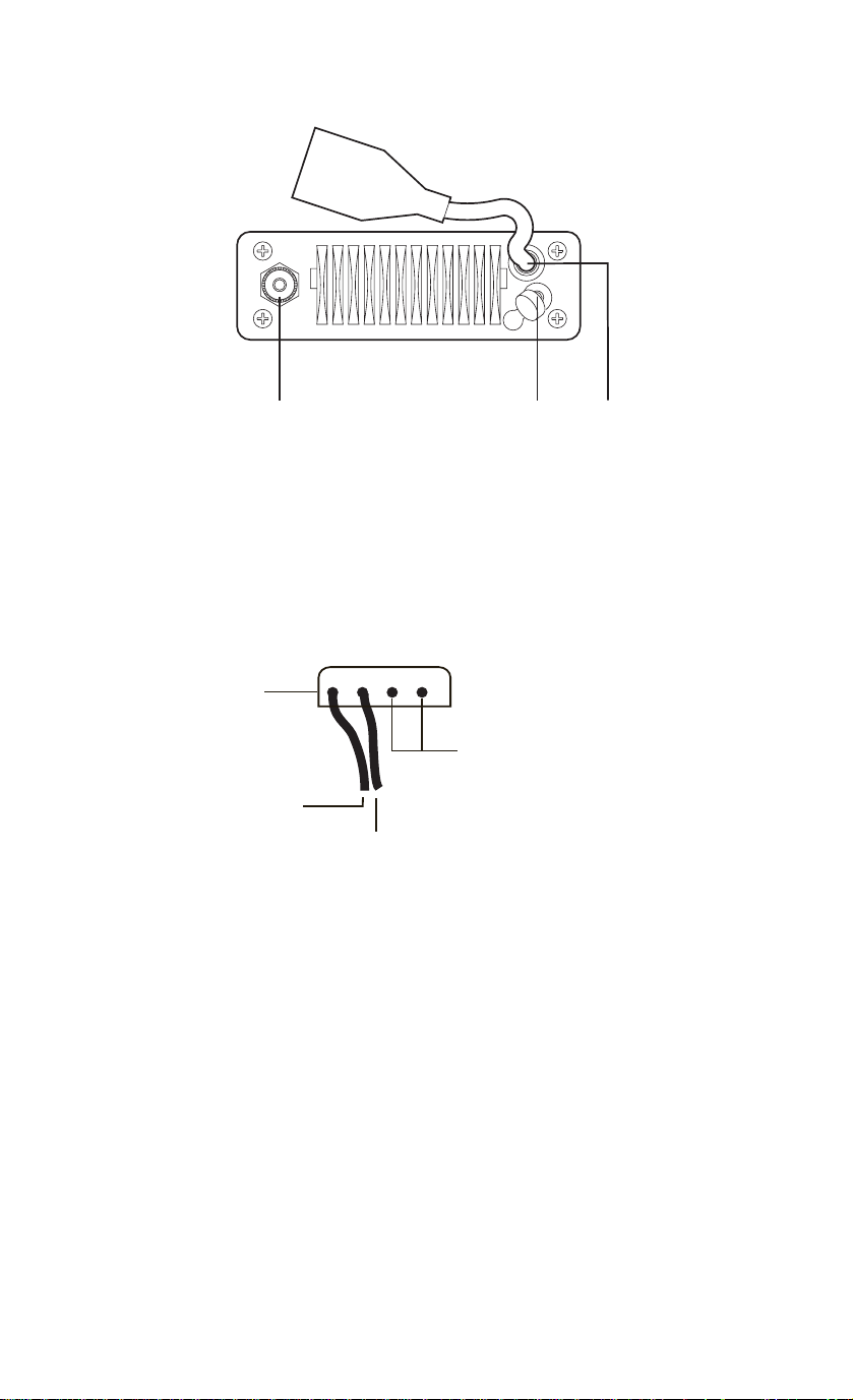
Rear Panel Connectors
11 1012
10. DC Power and PA Speaker Output - The “Pigtail” cord and connector are
power in and PA Speaker out.
11. Remote Speaker Connector - An external 4 ohm, 4 Watt speaker may be
connected to this jack. The connecting wire must have a miniature plug.
12. Antenna Connector - Connect the antenna here using a type PL259
connector.
34
P A Speaker Out
(Using supplied pins)
+13.8V
Ground
Supplied Power Cord - Connect supplied power cord to the keyed
connector.
5
Page 9

19
20 211522
18
17
16
14
13
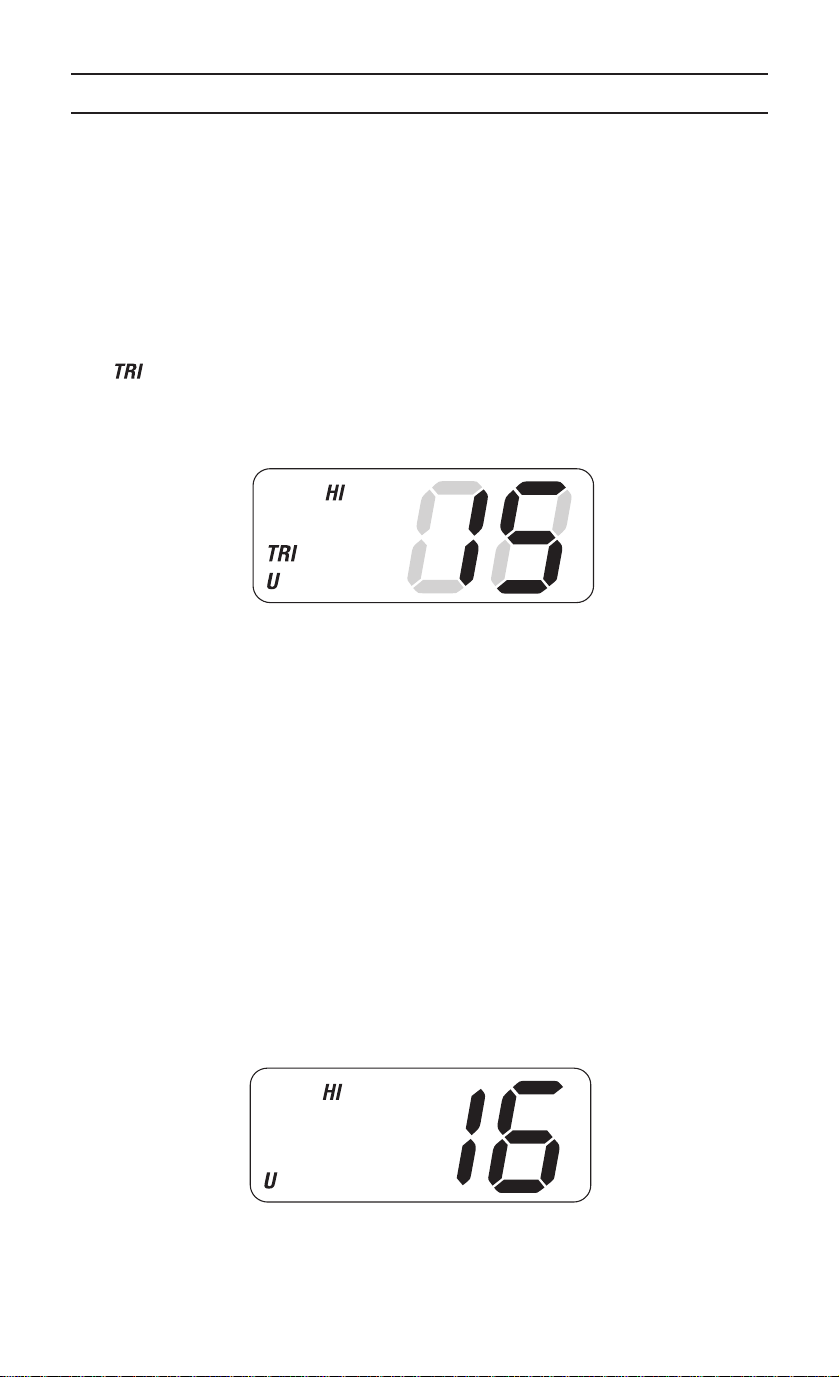
13. LCD Numerical Channel Display - Indicates Channel Number in use.
Weather Channels are displayed as single digits. (Example: 0, 1, 2, 3,
etc.) Communication Channels are displayed as two digits (Example: 01,
02, 03, etc.).
Note: LCD Status Indicators appear when status is selected by
pressing the corresponding button.
14. WX - Indicates Weather Channel Mode has been activated. When
pressed, remains active for eight (8) seconds.
15.
(Weather Alert) - Indicates Weather Alert mode.
16. U (US) - Indicates US Channel Mode.
I (International) - Indicates International Channel Mode.
C (Canada) - Indicates Canada Channel Mode.
17. TRI (Triple Watch) - Indicates Triple Watch Mode is in effect.
18. SCAN - Indicates Normal Scan Mode.
19. TX (Transmit) - LED lights when transmitting.
20. HI (High) - Indicates transmitted output is 25 Watts.
21. LO (Low) - Indicates transmitted output is 1 Watt.
22. MEM (Memory) - Indicates Memory Scan Mode status for each channel
selected.
6
Page 10

Multi-Function Keys
76 453 2
3. STEP - This key is used to step through the channels entered in the
Memory Scan Mode. When pressed and held, this key also starts and
stops the SCAN Mode.
• Press STEP to step to a desired channel.
• Press and hold STEP to begin the Channel Scan Mode and initiate
Triple Watch automatically.
4. H/L - This key is used to switch between HI (25 Watts) where allowed, or
LO (1 Watt) output power. When pressed and held, this key activates the
PA mode and, when used in conjunction with the MEM key, this key
adjusts the brightness of the LCD Panel and the TX LED indicator.
• Press H/L to switch between HI and LO output power.
• Press and hold H/L to access the Public Address Mode.
• Press and hold MEM, and then press H/L to adjust the brightness
of the LCD Panel backlight and the brightness of the TX LED
indicator.
The LCD Panel backlight and TX LED indicator are at their
brightest level when the MC 1020 is shipped from the factory.
5. MEM - This key enters channels in the Memory Scan Mode. When used
in conjunction with H/L, the LCD Panel lighting can be adjusted. When
used in conjunction with the 16/9 key, the Channel Mode of Operation can
be selected.
• Press MEM to enter a selected channel in Memory Scan Mode.
• Press and hold MEM, then press H/L to adjust the LCD Panel light
intensity from a bright to a dim setting. Repeat this action to return
to the bright intesity setting.
• Press and hold MEM, and then press 16/9 to change the Channel
Mode of Operation between US, International, or Canada.
7
Page 11

6. 16/9 - This key is used to instantly access Channel 16 and Channel 9
communications. This key is also used to access Triple Watch, and when
used in conjunction with MEM, this key lets you change between Channel
Modes of Operation.
• Press 16/9 to access instant Channel 16/Channel 9
communications.
• Press and hold 16/9 to turn Triple Watch On/Off.
• Press MEM, then press 16/9 to switch between US, International or
Canada Channel Modes.
7. WX (Weather) - This key is used to switch between monitoring weather
channels and communication channels. This key is also used to activate
the Weather Alert Mode.
• Press WX to switch between weather and communication
channels.
• Press and hold WX to turn the Weather Alert Mode On/Off.
8
Page 12
Operation
1. Turn the unit on by rotating the VOL control clockwise.
2. Adjust the SQUELCH control counterclockwise until you hear background
noise, and then turn it clockwise until the noise just disappears.
Triple Watch
Triple Watch monitors Channel 16 and Channel 9 for activity every two
seconds while scanning or monitoring.
To activate Triple Watch, press and hold 16/9 until two short beeps occur.
The indicator appears on the LCD panel, indicating Triple Watch mode is
in effect. If a signal is received on either Channel 16 or Channel 9, the radio
remains on that channel until the signal ends
.
Press and hold 16/9 until the tone sounds to cancel Triple Watch Mode.
Manual Tuning
To manually select a channel, press the CHAN selector buttons (up/down) to
select the desired channel. Weather Channels are located on Channels0-9.
Communication Channels are located on Channels 01 - 28 and 60 - 88.
Instant Channel 16/Channel 9 Communications
To access instant Channel 16 or Channel 9 communications, press 16/9. This
overrides the channel selected with the CHAN selector buttons or any
scanning activity. The Channel Display indicates the unit is on Channel 16.
Press 16/9 again to access Channel 9 communications. Press and release
16/9 a third time to release the switch (Off). The transceiver will return to the
channel selected prior to accessing instant Channel 16/Channel 9
communications. The Channel Display will indicate the selected channel.
9
Page 13

To cancel Channel 16/Channel 9 communications:
• Press 16/9 until previous channel setting appears.
—or—
• Press WX.
Weather Scan
To scan only Weather Channels0-9,press WX, and then press and hold
STEP. The indicator will appear on the LCD Panel, indicating Weather
Mode.
To exit from Weather Scanning:
• Press and hold STEP to end scan.
• Press 16/9 to change to Channel 16/Channel 9 communications
—or—
• Press WX to change to standard channel communications.
US/International/Canadian Channels
To select operation (communication and scanning) on US Channels, press
MEM, then press 16/9 while holding MEM. U (USA), I (International), or C
(Canadian) will appear on the LCD Panel.
Select the appropriate mode for operation.
MEM (Entering channel numbers into Memory Scan)
You can enter channels into Memory Scan for instant scanning at any time.When
a channel is selected for Memory Scan, the indicator will appear on the
LCD display.
To enter a channel number into Memory Scan, select the channel number you
want stored by pressing the CHAN Selector button up or down, and then press
MEM.
Note: In order for all functions of the MC 1020 to work properly, at
least two channel numbers must be entered into Memory Scan
before operating the radio.
10
Page 14

Memory Scan
To scan channels stored in Memory Scan, press and hold STEP. In the
Memory Scan Mode, the MC 1020 scans only those channel numbers
previously entered into Memory Scan. If no channel has been entered into
Memory Scan, the error tone sounds and the LCD Panel does not change.
Note: While in SCAN, pressing the 16/9 button three times or pressing
and holding STEP will return the radio to the channel it was on prior
to accessing Memory Scan.
Public Address
To access the Public Address Mode, press and hold H/L. The icon will
appear in the display. Press the Press-To-Talk switch on the microphone, hold
the microphone approximately two inches from your mouth, and speak clearly
in a normal voice. To cancel , press and hold H/L.
Weather Alert
The Weather Alert Mode can be activated to alert you of dangerous weather.
When Weather Alert is turned on, and a warning signal is received, a siren will
sound at full volume, regardless of the VOL setting. When the signal stops,
you will hear the active weather channel broadcast at normal volume.
The icon indicates the Weather Alert Mode is activated. To activate the
Weather Alert Mode:
1. Press WX to select Weather mode press and hold WX.
2. Press and hold STEP to begin Weather Channel Scan.
—or—
1. Manually select the active Weather Channel after selecting WX.
2. Press and hold WX to activate the Weather Alert Mode. To cancel the
Weather Alert Mode, press and hold WX again.
11
Page 15

Transmitting
When the power is turned on, the transmitter is set for 25 Watts (except for
USA Channels 13 and 67). The HI indicator will appear on the LCD Panel,
indicating 25 Watt output power. In order to comply with FCC Regulations
contained in 47 CFR 80.215 (g) (3), USA Channels 13 and 67 transmit at 1
Watt regardless of the H/L selector setting. However, 25 Watt output for
emergency use is available by pressing H/L while pressing the Press-To-Talk
switch. When the H/L switch is released, the radio returns to the 1 Watt
position.
To switch to the LO (1 Watt) position, Press H/L. The LO indicator will appear
on the LCD Panel, indicating 1 Watt output power. The LO position should
always be used for in-port or short range communications.
Press H/L to switch to the HI (25 Watt) position. The HI indicator will appear on
the LCD Panel, indicating 25 Watt output power.
To activate the transmitter, press the Press-To-Talk switch on the microphone.
The LED indicator will light, indicating a signal is being transmitted.
Release the switch to receive. When transmitting, hold the microphone
approximately two inches from your mouth and speak clearly in a normal
voice. T h e microphone provided with your radio is a 500 ohm dynamic
type.
Note: You cannot transmit on Weather Channels0-9orChannel
15. The Channel Number in the LCD Panel will blink to indicate
these channels are “receive-only”.
Dimming the LCD Display Backlight and the TX Indicator
When the MC 1020 is turned on, the LCD Panel and LED will be
brightest. Pressing the MEM and H/L buttons will change the brightness.
The last setting will remain in memory. When you turn on the radio the next
time, the display will be at this setting.
Note that the LED is not turned Off by the DIM button.
12
Page 16

Optional Accessories
• Flush mounting bracket for “in dash” installation.
Contact your Uniden Dealer for information.
13
Page 17

VHF FM Marine RadioTelephone
Channel and Functions
(USA Channels)
CHANNEL FREQUENCY (MHz) TYPE OF SHIP SHIP PERMANENT
DESIG TRANSMIT RECEIVE TRAFFIC TO SHIP TO SHORE SCAN LIST
WX0 — 163.275 NOAA Weather RX Only RX Only Weather
WX1 — 162.550 NOAA Weather RX Only RX Only Weather
WX2 — 162.400 NOAA Weather RX Only RX Only Weather
WX3 — 162.475 NOAA Weather RX Only RX Only Weather
WX4 — 162.425 NOAA Weather RX Only RX Only Weather
WX5 — 162.450 NOAA Weather RX Only RX Only Weather
WX6 — 162.500 NOAA Weather RX Only RX Only Weather
WX7 — 162.525 NOAA Weather RX Only RX Only Weather
WX8 — 161.650 Can. Weather RX Only RX Only Weather
WX9 — 161.775 Can. Weather RX Only RX Only Weather
01 156.050 156.050 VTS Yes Yes
02
03 156.150 156.150 Port Ops Yes Yes
05 156.250 156.250 VTS Yes Yes
06 156.300 156.300 Safety Yes No Coast Guard
07 156.350 156.350 Com’l Yes Yes
08 156.400 156.400 Com’l Yes No
09 156.450 156.450 Com’l & Non Com’l Yes Yes Fish
10 156.500 156.500 Com’l Yes Yes
11 156.550 156.550 Com’l Yes Yes
12 156.600 156.600 Port Ops Yes Yes
13 156.650 156.650 Navigational, TX 1W only Yes Yes
14 156.700 156.700 Port Ops Yes Yes
15 — 156.750 Environmental RX Only RX Only Environmental
16 156.800 156.800 Safety Calling Yes Yes
17 156.850 156.850 State Control Yes Yes
18 156.900 156.900 Com’l Yes Yes
19 156.950 156.950 Com’l Yes Yes,
20 157.000 161.600 Port Ops, RX Duplex Yes Yes
21 157.050 157.050 Coast Guard Yes Yes Coast Guard
22 157.100 157.100 Coast Guard Yes Yes Coast Guard
23 157.150 157.150 Coast Guard Yes Yes Coast Guard
24 157.200 161.800 Public Corresp,Duplex No Yes Busy Tel.
25 157.250 161.850 Public Corresp,Duplex No Yes Busy Tel.
26 157.300 161.900 Public Corresp,Duplex No Yes Busy Tel.
27 157.350 161.950 Public Corresp,Duplex No Yes Busy Tel.
28 157.400 162.000 Public Corresp,Duplex No Yes Busy Tel.
60
61 156.075 156.075
63 156.175 156.175
64 156.225 156.225
65 156.275 156.275 Port Ops Yes Yes
66 156.325 156.325 Port Ops Yes Yes
67 156.375 156.375 Com’l, TX 1W only Yes No
68 156.425 156.425 Non Com’l Yes Yes Fish
69 156.475 156.475 Non Com’l Yes Yes Fish
71 156.575 156.575 Non Com’l Yes Yes Fish
72 156.625 156.625 Non Com’l Yes No Fish
73 156.675 156.675 Port Ops Yes Yes
74 156.725 156.725 Port Ops Yes Yes
77 156.875 156.875 Port Ops Yes No
78 156.925 156.925 Non Com’l Yes Yes Fish
79 156.975 156.975 Com’l Yes Yes
80 157.025 157.025 Com’l Yes Yes
81 157.075 157.075 Coast Guard Yes Yes Coast Guard
82 157.125 161.725 US Govt Only Yes Yes
83 157.175 157.175 Coast Guard Yes Yes Coast Guard
84 157.225 161.825 Public Corresp,Duplex No Yes Busy Tel.
85 157.275 161.875 Public Corresp,Duplex No Yes Busy Tel.
86 157.325 161.925 Public Corresp,Duplex No Yes Busy Tel.
87 157.375 161.975 Public Corresp,Duplex No Yes Busy Tel.
88 157.425 157.425 Com’l Yes No
14
Page 18

VHF FM Marine RadioTelephone
Channel and Functions
(International Channels)
CHANNEL FREQUENCY (MHz) TYPE OF SHIP SHIP PERMANENT
DESIG TRANSMIT RECEIVE TRAFFIC TO SHIP TO SHORE SCAN LIST
WXO — 163.275 NOAA Weather RX Only RX Only Weather
WX1 — 162.550 NOAA Weather RXOnly RX Only Weather
WX2 — 162.400 NOAA Weather RXOnly RX Only Weather
WX3 — 162.475 NOAA Weather RXOnly RX Only Weather
WX4 — 162.425 NOAA Weather RXOnly RX Only Weather
WX5 — 162.450 NOAA Weather RXOnly RX Only Weather
WX6 — 162.500 NOAA Weather RXOnly RX Only Weather
WX7 — 162.525 NOAA Weather RXOnly RX Only Weather
WX8 — 161.650 Can. Weather RXOnly RX Only Weather
WX9 — 161.775 Can. Weather RXOnly RX Only Weather
01 156.050 160.650 VTS,Duplex Yes Yes
02 156.100 160.700 Port Ops,Duplex Yes Yes
03 156.150 160.750 Port Ops,Duplex Yes Yes
04 156.200 160.800 Port Ops,Duplex Yes Yes
05 156.250 160.850 VTS,Duplex Yes Yes
06 156.300 156.300 Safety Yes No
07 156.350 160.950 Com’,Duplexl Yes Yes
08 156.400 156.400 Com’l Yes No
09 156.450 156.450 Com’l & Non Com’l Yes Yes Fish
10 156.500 156.500 Com’l Yes Yes
11 156.550 156.550 Com’l Yes Yes
12 156.600 156.600 Port Ops Yes Yes
13 156.650 156.650 Navigational Yes Yes
14 156.700 156.700 Port Ops Yes Yes
15 156.750 156.750 Environmental Yes Yes Environmental
16 156.800 156.800 Safety Calling Yes Yes
17 156.850 156.850 State Control Yes Yes
18 156.900 161.500 Com’l,Duplex Yes Yes
19 156.950 161.550 Com’l,Duplex Yes Yes
20 157.000 161.600 Port Ops,Duplex Yes Yes
21 157.050 161.650 Coast Guard,Duplex Yes Yes
22 157.100 161.700 Coast Guard,Duplex Yes Yes
23 157.150 161.750 Coast Guard,Duplex Yes Yes
24 157.200 161.800 Public Corresp,Duplex No Yes Busy Tel.
25 157.250 161.850 Public Corresp,Duplex No Yes Busy Tel.
26 157.300 161.900 Public Corresp,Duplex No Yes Busy Tel.
27 157.350 161.950 Public Corresp,Duplex No Yes Busy Tel.
28 157.400 162.000 Public Corresp,Duplex No Yes Busy Tel.
60 156.025 160.625 Duplex
61 156.075 160.675 Duplex
62 156.125 160.725 Duplex
63 156.175 160.775 Duplex
64 156.225 160.825 Duplex
65 156.275 160.875 Port Ops,Duplex Yes Yes
66 156.325 160.925 Port Ops,Duplex Yes Yes
67 156.375 156.375 Com’l Yes No
68 156.425 156.425 Non Com’l Yes Yes Fish
69 156.475 156.475 Non Com’l Yes Yes Fish
71 156.575 156.575 Non Com’l Yes Yes Fish
72 156.625 156.625 Non Com’l Yes No Fish
73 156.675 156.675 Port Ops Yes Yes
74 156.725 156.725 Port Ops Yes Yes
77 156.875 156.875 Port Ops Yes No
78 156.925 161.525 Non Com’l,Duplex Yes Yes
79 156.975 161.575 Com’l,Duplex Yes Yes
80 157.025 161.625 Com’l,Duplex Yes Yes
81 157.075 161.675 Coast Guard,Duplex Yes Yes Coast Guard
82 157.125 161.725 US Govt Only,Duplex Yes Yes
83 157.175 161.775 Coast Guard,Duplex Yes Yes Coast Guard
84 157.225 161.825 Public Corresp,Duplex No Yes Busy Tel.
85 157.275 161.875 Public Corresp,Duplex No Yes Busy Tel.
86 157.325 161.925 Public Corresp,Duplex No Yes Busy Tel.
87 157.375 161.975 Public Corresp,Duplex No Yes Busy Tel.
88 157.425 162.025 Com’l,Duplex Yes No Busy Tel.
15
Page 19

VHF FM Marine RadioTelephone
Channel and Functions
(Canadian Channels)
CHANNEL FREQUENCY (MHz) TYPE OF SHIP SHIP PERMANENT
DESIG TRANSMIT RECEIVE TRAFFIC TO SHIP TO SHORE SCAN LIST
WXO — 163.275 NOAA Weather RX Only RX Only Weather
WX1 — 162.550 NOAA Weather RXOnly RX Only Weather
WX2 — 162.400 NOAA Weather RXOnly RX Only Weather
WX3 — 162.475 NOAA Weather RXOnly RX Only Weather
WX4 — 162.425 NOAA Weather RXOnly RX Only Weather
WX5 — 162.450 NOAA Weather RXOnly RX Only Weather
WX6 — 162.500 NOAA Weather RXOnly RX Only Weather
WX7 — 162.525 NOAA Weather RXOnly RX Only Weather
WX8 — 161.650 Can. Weather RXOnly RX Only Weather
WX9 — 161.775 Can. Weather RXOnly RX Only Weather
01 156.050 160.650 Duplex Yes Yes
02 156.100 160.700 Duplex Yes Yes
03 156.150 160.750 Duplex Yes Yes
04 156.200 156.200 Yes Yes
05 156.250 156.250 Yes Yes
06 156.300 156.300 Yes No
07 156.350 156.350 Yes Yes
08 156.400 156.400 Yes No
09 156.450 156.450 Yes Yes Fish
10 156.500 156.500 Yes Yes
11 156.550 156.550 Yes Yes
12 156.600 156.600 Yes Yes
13 156.650 156.650 1W Yes Yes
14 156.700 156.700 Yes Yes
15 156.750 156.750 1W Yes Yes Environmental
16 156.800 156.800 Yes Yes
17 156.850 156.850 1W Yes Yes
18 156.900 161.500 Yes Yes
19 156.950 161.550 Yes Yes
20 157.000 161.900 Duplex, 1W Yes Yes
21 157.050 157.050 Yes Yes
22 157.100 157.100 Yes Yes
23 157.150 161.750 Duplex Yes Yes
24 157.200 161.800 Duplex No Yes Busy Tel.
25 157.250 161.850 Duplex No Yes Busy Tel.
26 157.300 161.900 Duplex No Yes Busy Tel.
27 157.350 161.950 Duplex No Yes Busy Tel.
28 157.400 162.000 Duplex No Yes Busy Tel.
60 156.025 160.625 Duplex
61 156.075 156.075
62 156.125 156.125
63 156.175 156.175
64 156.225 160.825 Duplex
65 156.275 156.275 Yes Yes
66 156.325 156.325 Yes Yes
67 156.375 156.375 Yes No
68 156.425 156.425 Yes Yes Fish
69 156.475 156.475 Yes Yes Fish
71 156.575 156.575 Yes Yes Fish
72 156.625 156.625 Yes No Fish
73 156.675 156.675 Yes Yes
74 156.725 156.725 Yes Yes
77 156.875 156.875 Yes No
78 156.925 156.925 Yes Yes
79 156.975 156.975 Yes Yes
80 157.025 157.025 Yes Yes
81 157.075 157.075 Yes Yes Coast Guard
82 157.125 157.125 Yes Yes
83 157.175 157.175 Yes Yes Coast Guard
84 157.225 161.825 Duplex No Yes Busy Tel.
85 157.275 161.875 Duplex No Yes Busy Tel.
86 157.325 161.925 Duplex No Yes Busy Tel.
87 157.375 161.975 Duplex No Yes Busy Tel.
88 157.425 162.025 Duplex Yes No Busy Tel.
16
Page 20

Specifications
General
Channels : Transmit 54
Controls : On-Off/Volume, Squelch
Status Indicators : TX LED (transmit), SCAN, TRI, U, I, C, HI, LO,
Channel Display : LCD (Dual 7 segment)
Selector Switch : Channel Selector switch
Buttons : WX, 16/9, MEM, H/L, and STEP
Connectors : Antenna, remote speaker, and DC power
Size : 2 1/5"H x 6 2/5"W x 8"L
Weight : 2.4 lbs
Supply Voltage : 13.8V DC negative ground
Standard Accessories : Mounting bracket and hardware, DC power cord,
Antenna Impedance
Microphone
Speaker
Operating Temperature Range : – 20°C to +50°C (– 4°F to +122°F)
Shock and Vibration : Meets or exceeds EIA standards, RS152B and
FCC Approvals : Type accepted under part 80 of the Rules; meets
Transmitter
Power Output : 1 watt or 25 watt (switch selectable)
Power Requirement : Not rated on LO;
Modulation
Hum and Noise Signal-to-Noise : 42 dB@300 HZ, 3kHZ (nominal)
Audio Distortion : Less than 3% with 3 kHz deviation with 1000 Hz
Spurious Suppression : – 56 dB @ 1 watt, – 65 dB @ 25 watts
Output Power Stabilization : Built-in automatic level control (ALC)
Frequency Range : 156 to 158 MHz
Frequency Stability:
Receiver
Frequency Range : 156 to 163 MHz
Sensitivity
Circuit : Dual Conversion Super Heterodyne PLL
Squelch Sensitivity
Spurious Response : 60 dB
Adjacent Channel Selectivity
Audio Output Power : 3.0 watts (10% Distortion)
Power Requirement : 230 mA @ 13.8V DC squelched
IF Frequencies : 1st - 16.9 MHz
Receive 77 Marine/10 Weather
MEM, WX, and WX alert symbol on LCD Panel
microphone hanger, spare fuse
:50Ω nominal
: Rugged 1kΩ condenser mic element with coiled
cord
: 1.82 inch, 8Ω
RS204C
Great Lakes Agreement and party boat
requirements
25 watts output: 4.5A@13.8V DC
:FM±5 kHz deviation (FCC designator F3E)
modulating frequency (nominal)
: ±1.58 kHz @ – 20°C to +50°C
: 0.25µV for 12 dB SINAD
0.35µV for 20 dB S/N
: 0.5µv Threshold
:60dB@±25 kHz
0.7A @ 13.8V DC at maximum audio output
2nd - 455 kHz
17
Page 21

Care and Maintenance
Your MC 1020 is a precision piece of electronic equipment and you should
treat it accordingly. Due to the rugged design, very little maintenance is
required. However, a few precautions should be observed:
• If your radio has been accidentally subjected to spray or splash,
you should immediately wipe it down with a soft cloth dampened
with fresh water.
• If the antenna has been damaged, you should not transmit except
in case of emergency. A defective antenna may cause damage to
your radio.
• You are responsible for the continued FCC technical compliance of
your radio.
• You are urged to arrange for periodic performance checks with
your Uniden Marine Dealer.
18
Page 22

Three Year Limited Warranty
WARRANTOR: UNIDEN AMERICA CORPORATION (Uniden)
ELEMENTS OF WARRANTY: Uniden warrants, for three years, to the original retail
owner, this Uniden Product to be free from defects in materials and craftsmanship with
only the limitations or exclusions set out below.
WARRANTY DURATION: This warranty to the original user shall terminate and be of
no further effect 36 months after the date of original retail sale. The warranty is invalid if
the Product is (A) damaged or not maintained as reasonable or necessary, (B)
modified, altered, or used as part of any conversion kits, subassemblies, or any
configurations not sold by Uniden, (C) improperly installed, (D) serviced or repaired by
someone other than an authorized service center for a defect or malfunction covered by
this warranty, (E) used in any conjunction with equipment or parts or as part of any
system not manufactured by Uniden, or (F) installed or programmed by anyone other
than as detailed by the Operating Guide for this product.
STATEMENT OF REMEDY: In the event that the product does not conform to this
warranty at any time while this warranty is in effect, warrantor will repair the defect and
return it to you without charge for parts, service, or any other cost (except shipping and
handling) incurred by warrantor or its representatives in connection with the
performance of this warranty. THE LIMITED WARRANTY SET FORTH ABOVE IS
THE SOLE AND ENTIRE WARRANTY PERTAINING TO THE PRODUCT AND IS IN
LIEU OF AND EXCLUDES ALL OTHER WARRANTIES OF ANY NATURE
WHATSOEVER, WHETHER EXPRESS, IMPLIED OR ARISING BY OPERATION OF
LAW, INCLUDING, BUT NOT LIMITED TO ANY IMPLIED WARRANTIES OF
MERCHANTABILITY OR FITNESS FOR A PARTICULAR PURPOSE. THIS
WARRANTY DOES NOT COVER OR PROVIDE FOR THE REIMBURSEMENT OR
PAYMENT OF INCIDENTAL OR CONSEQUENTIAL DAMAGES. Some states do not
allow this exclusion or limitation of incidental or consequential damages so the above
limitation or exclusion may not apply to you.
LEGAL REMEDIES: This warranty gives you specific legal rights, and you may also
have other rights which vary from state to state. This warranty is void outside the
United States of America.
PROCEDURE FOR OBTAINING PERFORMANCE OF WARRANTY: If, after following
the instructions in this Operating Guide you are certain that the Product is defective,
pack the Product carefully (preferably in its original packaging). Include evidence of
original purchase and a note describing the defect that has caused you to return it. The
Product should be shipped freight prepaid by traceable means, or delivered, to
warrantor at:
Uniden America Corporation
Parts and Service Division
4700 Amon Carter Blvd.
Ft. Worth, TX 76155
(800)586-0409, 8 AM to 5 PM Central, Monday through Friday
Page 23

®
© 1997, Uniden America Corporation. All Rights Reserved
Printed in the Philippines
Page 24

®
MC 1020
Radio Marítima VHF
Manual
de Instrucciones
UTZZ01868ZZ
Page 25

Operación de los servicios de radio marítima
¡Advertencia!
Este transmisor funciona en canales y frecuencias que tengan
uso restringido en los Estados Unidos. Las asignaciones de los
canales incluyen frecuencias asignadas para uso exclusivo de
los Guarda Costas de los Estados Unidos, para uso en Canadá
y en aguas internacionales. El uso de estas frecuencias sin la
debida autorización está terminantemente prohibido. Para
frecuencias y canales que actualmente son para uso en los
Estados Unidos sin una licencia individual, por favor llame al
Centro de Llamadas de la FCC al 1-888-CALL-FCC
(1-888-225-5322).
En el caso de personas que necesiten una licencia, como usuarios comerciales, se
debe obtener una solicitud de licencia de la oficina de la FCC más cercana.
Page 26

Contenidos
Uniden MC 1020...............................................1
Instalación ...................................................2
Selección de la ubicación.....................................2
Supresión del ruido del motor .................................3
Selección de la antena.......................................3
Instalación del MC 1020......................................3
Controles y indicadores .........................................4
Panel frontal...............................................4
Conectores del panel posterior ................................5
Mandos de funciones múltiples ................................7
Funcionamiento ...............................................9
Vigilancia Triple ............................................9
Sintonización manual........................................9
Comunicaciones instantáneas del Canal 16 y el Canal 9 ............9
Exploración meteorológica...................................10
Canales de EE.UU./Internacionales/Canadá.....................10
MEM (Introducción de números de canales en la Memoria de Exploración)
10
Memoria de Exploración ....................................11
Megafonía ...............................................11
Alerta Meteorológica .......................................11
Cómo transmitir ...........................................12
Atenuación de la luz de fondo de la pantalla de cristal líquido y del
indicador TX..............................................12
Accesorios opcionales .........................................13
La radio marítima VHF
Canales y funciones
(Canales de EE.UU)...........................................14
La radio marítima VHF
Canales y funciones
(Canales Internacionales).......................................15
La radio marítima VHF
Canales y funciones
(Canales de Canadá) ..........................................16
Especificaciones..............................................17
Page 27

Uniden MC 1020
La radio marítima VHF, transmisor-receptor, Uniden MC 1020 ha sido diseñada para
darle un instrumento resistente y fiable que le proporcionará años de servicio libre de
problemas.
Con el cuidado y mantenimiento adecuado, su Uniden MC 1020 durará más que su
nave actual y le servirá bien a bordo de otras más. Las amplias características y la
flexibilidad con las que está diseñado este transmisor-receptor de alta calidad evitarán
que quede obsoleto independientemente de los cambios de nave o ubicaciones
geográficas.
La excelencia técnica del Uniden MC 1020 está demostrada por la gran variedad de
usos para los que la Comisión Federal de Comunicaciones de los Estados Unidos
(FCC) lo ha encontrado apto. El Uniden MC 1020 es aceptable para uso obligatorio de
“barcos de fiesta”, para uso en barcos sujetos al Acuerdo de Radio de los Grandes
Lagos o los requisitos de puente a puente, para barcos comerciales y de ocio en
general, así como ciertas estaciones terrestres con servicio marítimo.
El Uniden MC 1020 tiene un diseño completamente de estado sólido con
componentes y materiales diseñados para ser más resistentes de lo necesario y
compatibles con el entorno marítimo. El transmisor-receptor utiliza empacaduras,
anillos obturadores, membranas herméticas y otros selladores para crear un armazón
a prueba de salpicaduras y para proteger los componentes electrónicos. La unidad se
puede montar en varias ubicaciones convenientes de su barco utilizando el soporte
universal de montaje.
Se le recomienda que lea el resto del manual de instrucciones detenidamente para
familiarizarse con las características y el funcionamiento de su transmisor-receptor y
contribuir así a la naturaleza duradera del aparato.
Guarde el recibo como prueba de compra en caso de necesitar servicio de garantía.
Las características, especificaciones y disponibilidad de los accesorios opcionales
están sujetas a cambio sin previo aviso.
1
Page 28

Instalación
Precaución: El MC 1020 funciona solamente con sistemas de batería de
Es importante determinar cuidadosamente la ubicación más apta del MC 1020 en su
barco. Deben tenerse en cuenta consideraciones eléctricas, mecánicas y
medioambientales. Debe seleccionar la mejor ubicación en todos los aspectos.
Tenga en cuenta la flexibilidad con la que está diseñado el MC 1020 para poder usar
su radio de la manera más conveniente. Lascaracterísticas a tener en cuenta son:
1. El soporte universal de montaje puede instalarse en la parte superior o inferior de
un estante, en una mampara o en el techo.
2. El conector de altavoz REMOTO puede usarse con un altavoz auxiliar.
3. Todas las conexiones son del tipo que se enchufa y desenchufa para poder sacar
la radio fácilmente.
4. El altavoz interno frontal permite el montaje conveniente en el tablero de
instrumentos utilizando el soporte opcional.
conexión a tierra negativa de 12 voltios nominales.
Selección de la ubicación
Hay varios factores importantes a considerar al seleccionar la ubicación de su MC 1020:
1. Seleccione una ubicación libre de rociaduras y salpicaduras.
2. Mantenga los cables de la batería lo más cortos posible. Es preferible la conexión
directa a la batería. Si no se puede hacer la conexión directa con el cable de
alimentación suministrado, toda extensión debe hacerse con un cable AWG no.
10. Para extensiones más largas, se debe utilizar un alambre de mayor grosor.
3. Mantenga el cable de la antena lo más corto posible. Un cable largo de antena puede
hacer que se pierda bastante rendimiento, tanto al recibir como al transmitir.
4. Coloque la antena en un lugar lo más alto posible y alejado de objetos de metal. El
alcance está en función directa de la altura de la antena.
5. Seleccione un lugar que no permita que la radio esté expuesta a la luz directa del
sol (inclusive la que entre a través de ventanas).
6. Seleccione un lugar que permita el flujo del aire alrededor del disipador térmico
en la parte trasera de la radio.
7. Seleccione un lugar bien alejado de la brújula del barco. Los altavoces auxiliares
deben ubicarse también alejados de la brújula.
2
Page 29

Supresión del ruido del motor
La interferencia del ruido de impulso generado por los sistemas eléctricos de los
motores a veces es un problema para las radios. El MC 1020 ha sido diseñado para
quedar esencialmente aislado al ruido de impulso del encendido y al ruido del
alternador. No obstante, en algunas instalaciones, es posible que sea necesario tomar
medidas para reducir todavía más el efecto de la interferencia del ruido. Todos los
cables de CC de la batería, el cable de la antena y los cables accesorios deben estar
alejados del motor y del compartimento del motor, así como de cables de alta
corriente.
En casos extremos de interferencia de ruido de impulso, es posible que sea necesario
instalar un dispositivo de supresión de ruido. Comuníquese con su distribuidor de Uniden
para obtener más información.
Selección de la antena
Hay un número de antenas disponibles de varios proveedores de calidad. Se sugiere
seguir la recomendación de su distribuidor de Uniden para escoger una antena apta
para su barco y sus necesidades de alcance.
En general, el alcance de comunicación aumenta utilizando una antena de alta
ganancia, colocada lo más alto posible sobre el nivel del agua. Las antenas deben
colocarse alejadas de objetos de metal y no deben tener cables de alimentación
coaxiales excesivamente largos.
Instalación del MC 1020
Una vez que haya analizado cuidadosamente los diferentes factores que afectan su
ubicación, coloque la radio (con el soporte, micrófono, cable de alimentación, antena y
los cables auxiliares instalados) en el lugar seleccionado para asegurarse de que no
hay interferencia de los objetos de alrededor. Marque la ubicación del soporte de
montaje. Quite el soporte de la radio y úselo como plantilla para marcar los agujeros
que va a taladrar para los materiales de montaje. Taladre los agujeros y monte el
soporte con materiales compatibles con el material de la superficie de montaje.
Conecte el alambre rojo del cable de alimentación incluido con la radio al suministro
positivo (+) de la batería. conecte el alambre negro del cable de alimentación a la
conexión a tierra. El cable de alimentación está equipado con un fusible para proteger
la radio. Use solamente un fusible de fundición rápida de seis (6) amperios como
repuesto. Conecte el cable de alimentación al conector flexible compatible.
Conecte la antena y todos los demás cables y accesorios auxiliares.
Instale la radio en el soporte de montaje y conecte todos los cables y accesorios en los
enchufes y conectores correspondientes
3
Page 30

Panel frontal
Controles y indicadores
8
91
76 453 2
1. VOLUME (Encendido/Apagado/Volumen) - Enciende y apaga el MC 1020 y
cambia el nivel del sonido.
2. SQUELCH (Silenciador) - Elimina el ruido de fondo cuando no se está recibiendo
ninguna señal.
Nota: Los puntos 3 al 7 (inclusive) son mandos de funciones múltiples. Consulte
la sección “Mandos de funciones múltiples” para ver una descripción
detallada.
3. STEP (también se encuentra en el micrófono)
4. H/L (Alta/Baja)
5. MEM
6. 16/9 (Canal 16/Canal 9; también se encuentra en el micrófono)
WX (Tiempo meteorológico)
7.
8. CHAN - Este control se utiliza para seleccionar manualmente el canal de
comunicación deseado (01 - 28 y 60 - 68), o el canal meteorológico (0 - 9).
9. Panel LCD (Pantalla de cristal líquido) - Indicadores de TX, SCAN, TRI,UIC,HI,
LO, MEM, WX, WX ALERT, y número de canal.
4
Page 31

Conectores del panel posterior
11 1012
10. Alimentación de DC y salida del altavoz PA (Megafonía) - El cable flexible con el
conector es para entrada de corriente y salida de megafonía.
11. Conector de altavoz remoto - Se puede conectar un altavoz externo de 4 ohmios
y 4 vatios a este enchufe. El cable de conexión debe tener un enchufe miniatura.
12. Conector de antena - Conecte aquí la antena usando un conector del tipo PL259.
Cable de alimentación suministrado - Conecte el cable de alimentación
suministrado al conector marcado.
5
Page 32

19
20 211522
18
17
16
14
13
13. LCD que indica el número de canal - Indica el número de canal en uso. Los
canales meteorológicos aparecen con un solo dígito. (Ejemplo: 0, 1, 2, 3, etc.).
Los canales de comunicación aparecen indicados con dos dígitos. (Ejemplo: 01,
02, 03, etc.).
Nota: Los indicadores del estado de la pantalla aparecen cuando se
selecciona el estado oprimiendo el botón correspondiente.
14. WX - Indica que el Modo de Canal Meteorológico se ha activado. Al oprimirlo,
sigue activo durante ocho (8) segundos.
15.
( Alerta Meteorológica) - Indica el Modo de Alerta Meteorológica.
16. U (USA) - Indica Modo de Canales de EE.UU.
I (Internacional) - - Indica el Modo de Canales Internacionales.
C (Canadá) - Indica el Modo de Canales de Canadá.
17. TRI (Vigilancia Triple) - Indica que está puesto el Modo de Vigilancia Triple.
18. SCAN - Indica el Modo de Exploración Normal.
19. TX (Transmitir) - El LED se enciende cuando se está transmitiendo.
20. HI (Alta) - Indica una salida de transmisión de 25 vatios.
21. LO (Baja) - Indica una salida de transmisión de 1 vatio.
22. MEM (Memoria) - Indica el estado de Modo de Memoria de Exploración para
cada canal seleccionado.
6
Page 33

Mandos de funciones múltiples
76 453 2
3. STEP - Este botón se usa para pasar por los canales introducidos en el Modo de
Memoria de Exploración. Al pulsarlo y mantenerlo pulsado, este botón también
inicia y detiene el Modo SCAN.
Oprima STEP para pasar al canal deseado.
•
Oprima el botón STEP y manténgalo oprimido para empezar el Modo de
•
Exploración de Canal e iniciar la Vigilancia Triple automáticamente.
4. H/L - Este botón se usa para cambiar entre potencia de salida HI (Alta) (25
vatios), cuando esté permitido, y LO (Baja) (1 vatio). Al oprimirlo y mantenerlo
oprimido, este botón activa el Modo de Megafonía y, al usarlo junto con el botón
MEM, este botón ajusta el brillo de Panel LCD y el indicador LED TX.
• Oprima H/L para cambiar entre potencia de salida HI (Alta) y LO (Baja).
• Oprima y mantenga oprimido el botón H/L para acceder al Modo de
Megafonía.
• Oprima y mantenga el botón MEM, y luego oprima H/L para ajustar el brillo
de la luz de fondo de Panel LCD y del indicador LED TX. La luz de fondo
de Panel LCD y el indicador LED TX se envían de fábrica en el nivel de
mayor brillo.
5. MEM - Este botón introduce los canales en el Modo de Memoria de Exploración.
Al usarse junto con el botón H/L, se puede ajustar la luz de la pantalla de cristal
líquido. Cuando se usa junto con el botón 16/9, se selecciona el Modo de
Operación de Canales.
•
Oprima MEM para introducir un canal seleccionado en el Modo de
Memoria de Exploración.
•
Oprima y mantenga oprimido MEM, luego oprima H/L para ajustar la
intensidad de la luz de la pantalla de cristal líquido de fuerte a tenue.
Repita esta operación para volver a la configuración previa de la
intensidad del brillo.
•
Oprima y mantenga oprimido el botón MEM, y luego pulse 16/9 para
cambiar el Modo de Operación de Canales entre EE.UU., Internacional y
Canadá.
7
Page 34

6. 16/9 - Este botón se usa para acceder instantáneamente a las comunicaciones
del Canal 16 y el Canal 9. Este botón también se usa para acceder al Modo de
Vigilancia Triple y, cuando se usa junto con el botón MEM, este botón le permite
cambiar entre los Modos de Operación de Canales.
Oprima 16/9 para acceder instantáneamente a las comunicaciones de
•
Canal 16/Canal 9.
Oprima y mantenga oprimido 16/9 para encender y apagar el Modo de
•
Vigilancia Triple.
Oprima MEM, y luego orpima 16/9 para cambiar entre los Modos de
•
Operación de Canales EE.UU., Internacional y Canadá.
7. WX (Weather) - (Tiempo Meteorológico) - Este botón se usa para cambiar entre
los canales meteorológicos y los canales de comunicación. Este botón se usa
también para activar el Modo de Alerta Meteorológica.
Oprima WXra cambiar entre los canales meteorológicos y los de
•
comunicaciones.
Oprima y mantenga oprimido el botón WX para encender o apagar el
•
Modo de Alerta Meteorológica.
8
Page 35

Funcionamiento
1. Encienda la unidad girando el control VOL en el sentido de las manecillas del
reloj.
2. Ajuste el control SQUELCH en sentido contrario a las manecillas del reloj hasta
que escuche ruido de fondo, y luego gírelo en el sentido de las manecillas del
reloj justo hasta que desaparezca el ruido.
Vigilancia Triple
La Vigilancia Triple sintoniza el Canal 16 y el Canal 9 cada dos segundos para ver si
hay actividad mientras está explorando o sintonizando otros canales.
Para activar la Vigilancia Triple, oprima y mantenga oprimido el botón 16/9 hasta que
oiga dos bips cortos. Aparecerá el indicador en la pantalla, indicando que el Modo
de Vigilancia Triple está activado. Si se recibe una señal en el Canal 16 o en el Canal
9, la radio se mantiene en ese canal hasta que termine la señal.
Oprima y mantenga oprimido 16/9 hasta que suene el tono para cancelar el Modo de
Vigilancia Triple.
Sintonización manual
Para seleccionar un canal manualmente, oprima los botones selectores de canales
(CHAN) (arriba/abajo) para seleccionar el canal deseado. Los canales meteorológicos
son los canales del 0 al 9. Los canales de comunicaciones son los canales del 01 al 28
y del 60 al 88.
Comunicaciones instantáneas del Canal 16 y el Canal 9
Para acceder instantáneamente a comunicaciones del Canal 16 o el Canal 9, oprima
16/9. Esto anula el canal seleccionado con los botones selectores de canal (CHAN) o
cualquier actividad de exploración. La pantalla de canales indica que la unidad está en
el Canal 16. Oprimiendo 16/9 otra vez se accede a las comunicaciones del Canal 9.
Oprima el botón 16/9 y suéltelo una tercera vez para desactivarlo (Off). El
transmisor-receptor regresará al canal seleccionado antes de acceder a las
comunicaciones instantáneas del Canal 16 y el Canal 9. El indicador de canal mostrará
en la pantalla el número del canal seleccionado.
9
Page 36

Para cancelar las comunicaciones del Canal 16 y el Canal 9:
Oprima el botón 16/9 hasta que aparezca la configuración del canal
•
anterior.
—O—
Oprima WX.
•
Exploración meteorológica
Para explorar solamente los Canales Meteorológicos 0 al 9, oprima WX, y luego
mantenga oprimido STEP. El indicador aparecerá en LCD Panel, indicando que el
Modo Meteorológico está activado.
Para salir de la Exploración Meteorológica:
Oprima y mantenga oprimido el botón STEP para finalizar la exploración.
•
Oprima 16/9ra cambiar a las comunicaciones del Canal 16 y el Canal 9.
•
—O—
Oprima WX para cambiar a las comunicaciones de canales estándares.
•
Canales de EE.UU./Internacionales/Canadá
Para seleccionar operación (comunicación y exploración) de canales de EE.UU.,
oprima MEM, luego oprima 16/9 mientras mantiene oprimido MEM. Aparecerá U
(EE.UU.), I (Internacional), o C (Canadá) en la pantalla.
Seleccione el modo de operación apropiado.
MEM (Introducción de números de canales en la Memoria de
Exploración)
Puede introducir canales en la Memoria de Exploración para una hacer una exploración
instantánea en cualquier momento. Cuando se selecciona un canal para la Exploración
de la Memoria, el indicador aparecerá en la pantalla.
Para introducir un número de canal en la Memoria de Exploración, seleccione el
número de canal que desee guardar oprimiendo el botón selector de canal (CHAN)
hacia arriba o hacia abajo, y luego oprima MEM.
Nota: Para que todas las funciones del MC 1020 funcionen
adecuadamente, debe haber un mínimo de dos números de canales
introducidos en la Memoria de Exploración antes de utilizar la radio.
10
Page 37

Memoria de Exploración
Para explorar canales guardados en la Memoria de Exploración, oprima y mantenga
oprimido STEP. En el Modo de Memoria de Exploración, el MC 1020 explora
solamente aquellos números de canales introducidos previamente en la Memoria de
Exploración. Si no hay ningún canal introducido en la Memoria de Exploración, suena
un tono de error y la pantalla no cambia.
Nota: Mientras esté en el modo SCAN, oprima el botón 16/9 tres veces o oprima
y mantenga oprimido el botón STEP para regresar al canal en el que
estaba antes de acceder a la Memoria de Exploración.
Megafonía
Para acceder al Modo de Megafonía, oprima y mantenga oprimido H/L. Aparecerá
en la pantalla. Oprima el botón Press-To-Talk del micrófono, sostenga el micrófono
a aproximadamente dos pulgadas de la boca y hable claramente en voz normal. Para
cancelar , oprima H/L unos segundos.
Alerta Meteorológica
El Modo de Alerta Meteorológica puede activarse para alertarlo de tiempo peligroso.
Cuando la Alerta Meteorológica está activada y se recibe una señal de advertencia,
sonará una sirena a todo volumen, independientemente de la configuración VOL .
Cuando la señal pare, oirá la emisión del canal meteorológico activo a volumen
normal.
Para activar el Modo de Alerta Meteorológica:
1. Oprima WX para seleccionar el Modo Meteorológico y manténgalo oprimido.
2. Oprima y mantenga oprimido STEP para empezar la Exploración de Canales
Meteorológicos.
—o—
1. Seleccione manualmente el Canal Meteorológico activo después de seleccionar
WX.
2.
Press and hold WX to activate the Weather Alert Mode. El icono indica que
el Modo de Alerta Meteorológica está activado.
Para cancelar el Modo de Alerta Meteorológica, oprima y mantenga oprimido WX
otra vez.
11
Page 38

Cómo transmitir
Al encender el aparato, el transmisor está configurado a 25 vatios (excepto para los
Canales 13 y 67 de EE.UU.). El indicador HI (Alta) aparecerá en la pantalla de cristal
líquido, indicando una potencia de salida de 25 vatios. Para cumplir con los
reglamentos de la FCC contenidos en 47 CFR 80.215 (g) (3), los Canales 13 y 67 de
EE.UU. transmiten a 1 vatio, independientemente de la configuración del selector H/L
(Alta/Baja). No obstante, dispone de salida de 25 vatios para caso de emergencia y se
obtiene oprimiendo H/L a la vez que se oprime el botón “Press to talk” (“Oprimir para
hablar”). Cuando se suelta el botón H/L, la radio regresa a la posición de 1 vatio.
Para cambiar a la posición LO (Baja) (1 vatio), oprima H/L. El indicador LO aparecerá
en la pantalla, indicando una potencia de salida de 1 vatio. La posición LO debe usarse
siempre para comunicaciones dentro del puerto o de corto alcance.
Para cambiar a la posición HI (Alta) (25 vatios), oprima H/L. El indicador HI aparecerá
en la pantalla de cristal líquido, indicando una potencia de salida de 25 vatios.
Para activar el transmisor, oprima el botón “Press to talk” (“Oprimir para hablar”) del
micrófono. El indicador LED TX se encenderá, indicando que se está transmitiendo
una señal. Para recibir, suelte el botón. Cuando esté transmitiendo, mantenga el
micrófono a aproximadamente dos pulgadas de la boca y hable claramente en una voz
normal. El micrófono incluido con la radio es del tipo dinámico de 500 ohmios.
Nota: No se puede transmitir en los Canales Meteorológicos 0 al 9 ni en el
Canal 15. El número de canal lucirá intermitentemente para indicar
que estos canales son para recibir solamente.
Atenuación de la luz de fondo de la pantalla de cristal
líquido y del indicador TX
Al encender el MC 1020, la LCD Panel y el están en su punto más brillante. Pulse
los botones MEM y H/L para cambiar el brillo.
La última configuración se guarda en la memoria. La próxima vez que encienda la
radio, la pantalla estará en dicha configuración.
Observe que el LED LED no se apaga con el botón DIM.
12
Page 39

Accesorios opcionales
• Soporte de montaje plano para empotrarlo en el tablero de
mandos.
Comuníquese con su distribuidor Uniden Uniden para información al respecto.
13
Page 40

La radio marítima VHF
Canales y funciones
(Canales de EE.UU)
DESIG FRECUENCIA (MHz) TIPO DE DE BARCO DEL BARCO
DE CANAL TX RX TRÁFICO A BARCO LA ORILLA
WX0 — 163.275 NOAA Weather RX Only RX Only
WX1 — 162.550 NOAA Weather RX Only RX Only
WX2 — 162.400 NOAA Weather RX Only RX Only
WX3 — 162.475 NOAA Weather RX Only RX Only
WX4 — 162.425 NOAA Weather RX Only RX Only
WX5 — 162.450 NOAA Weather RX Only RX Only
WX6 — 162.500 NOAA Weather RX Only RX Only
WX7 — 162.525 NOAA Weather RX Only RX Only
WX8 — 161.650 Can. Weather RX Only RX Only
WX9 — 161.775 Can. Weather RX Only RX Only
01 156.050 156.050 VTS Yes Yes
02
03 156.150 156.150 Port Ops Yes Yes
05 156.250 156.250 VTS Yes Yes
06 156.300 156.300 Safety Yes No
07 156.350 156.350 Com’l Yes Yes
08 156.400 156.400 Com’l Yes No
09 156.450 156.450 Com’l & Non Com’l Yes Yes
10 156.500 156.500 Com’l Yes Yes
11 156.550 156.550 Com’l Yes Yes
12 156.600 156.600 Port Ops Yes Yes
13 156.650 156.650 Navigational, TX 1W only Yes Yes
14 156.700 156.700 Port Ops Yes Yes
15 — 156.750 Environmental RX Only RX Only
16 156.800 156.800 Safety Calling Yes Yes
17 156.850 156.850 State Control Yes Yes
18 156.900 156.900 Com’l Yes Yes
19 156.950 156.950 Com’l Yes Yes,
20 157.000 161.600 Port Ops, RX Duplex Yes Yes
21 157.050 157.050 Coast Guard Yes Yes
22 157.100 157.100 Coast Guard Yes Yes
23 157.150 157.150 Coast Guard Yes Yes
24 157.200 161.800 Public Corresp,Duplex No Yes
25 157.250 161.850 Public Corresp,Duplex No Yes
26 157.300 161.900 Public Corresp,Duplex No Yes
27 157.350 161.950 Public Corresp,Duplex No Yes
28 157.400 162.000 Public Corresp,Duplex No Yes
60
61 156.075 156.075
63 156.175 156.175
64 156.225 156.225
65 156.275 156.275 Port Ops Yes Yes
66 156.325 156.325 Port Ops Yes Yes
67 156.375 156.375 Com’l, TX 1W only Yes No
68 156.425 156.425 Non Com’l Yes Yes
69 156.475 156.475 Non Com’l Yes Yes
71 156.575 156.575 Non Com’l Yes Yes
72 156.625 156.625 Non Com’l Yes No
73 156.675 156.675 Port Ops Yes Yes
74 156.725 156.725 Port Ops Yes Yes
77 156.875 156.875 Port Ops Yes No
78 156.925 156.925 Non Com’l Yes Yes
79 156.975 156.975 Com’l Yes Yes
80 157.025 157.025 Com’l Yes Yes
81 157.075 157.075 Coast Guard Yes Yes
82 157.125 161.725 US Govt Only Yes Yes
83 157.175 157.175 Coast Guard Yes Yes
84 157.225 161.825 Public Corresp,Duplex No Yes
85 157.275 161.875 Public Corresp,Duplex No Yes
86 157.325 161.925 Public Corresp,Duplex No Yes
87 157.375 161.975 Public Corresp,Duplex No Yes
88 157.425 157.425 Com’l Yes No
14
Page 41

La radio marítima VHF
Canales y funciones
(Canales Internacionales)
DESIG FRECUENCIA (MHz) TIPO DE DE BARCO DEL BARCO
DE CANAL TX RX TRÁFICO A BARCO LA ORILLA
WXO — 163.275 NOAA Weather RX Only RX Only
WX1 — 162.550 NOAA Weather RXOnly RX Only
WX2 — 162.400 NOAA Weather RXOnly RX Only
WX3 — 162.475 NOAA Weather RXOnly RX Only
WX4 — 162.425 NOAA Weather RXOnly RX Only
WX5 — 162.450 NOAA Weather RXOnly RX Only
WX6 — 162.500 NOAA Weather RXOnly RX Only
WX7 — 162.525 NOAA Weather RXOnly RX Only
WX8 — 161.650 Can. Weather RXOnly RX Only
WX9 — 161.775 Can. Weather RXOnly RX Only
01 156.050 160.650 VTS,Duplex Yes Yes
02 156.100 160.700 Port Ops,Duplex Yes Yes
03 156.150 160.750 Port Ops,Duplex Yes Yes
04 156.200 160.800 Port Ops,Duplex Yes Yes
05 156.250 160.850 VTS,Duplex Yes Yes
06 156.300 156.300 Safety Yes No
07 156.350 160.950 Com’,Duplexl Yes Yes
08 156.400 156.400 Com’l Yes No
09 156.450 156.450 Com’l & Non Com’l Yes Yes
10 156.500 156.500 Com’l Yes Yes
11 156.550 156.550 Com’l Yes Yes
12 156.600 156.600 Port Ops Yes Yes
13 156.650 156.650 Navigational Yes Yes
14 156.700 156.700 Port Ops Yes Yes
15 156.750 156.750 Environmental Yes Yes
16 156.800 156.800 Safety Calling Yes Yes
17 156.850 156.850 State Control Yes Yes
18 156.900 161.500 Com’l,Duplex Yes Yes
19 156.950 161.550 Com’l,Duplex Yes Yes
20 157.000 161.600 Port Ops,Duplex Yes Yes
21 157.050 161.650 Coast Guard,Duplex Yes Yes
22 157.100 161.700 Coast Guard,Duplex Yes Yes
23 157.150 161.750 Coast Guard,Duplex Yes Yes
24 157.200 161.800 Public Corresp,Duplex No Yes
25 157.250 161.850 Public Corresp,Duplex No Yes
26 157.300 161.900 Public Corresp,Duplex No Yes
27 157.350 161.950 Public Corresp,Duplex No Yes
28 157.400 162.000 Public Corresp,Duplex No Yes
60 156.025 160.625 Duplex
61 156.075 160.675 Duplex
62 156.125 160.725 Duplex
63 156.175 160.775 Duplex
64 156.225 160.825 Duplex
65 156.275 160.875 Port Ops,Duplex Yes Yes
66 156.325 160.925 Port Ops,Duplex Yes Yes
67 156.375 156.375 Com’l Yes No
68 156.425 156.425 Non Com’l Yes Yes
69 156.475 156.475 Non Com’l Yes Yes
71 156.575 156.575 Non Com’l Yes Yes
72 156.625 156.625 Non Com’l Yes No
73 156.675 156.675 Port Ops Yes Yes
74 156.725 156.725 Port Ops Yes Yes
77 156.875 156.875 Port Ops Yes No
78 156.925 161.525 Non Com’l,Duplex Yes Yes
79 156.975 161.575 Com’l,Duplex Yes Yes
80 157.025 161.625 Com’l,Duplex Yes Yes
81 157.075 161.675 Coast Guard,Duplex Yes Yes
82 157.125 161.725 US Govt Only,Duplex Yes Yes
83 157.175 161.775 Coast Guard,Duplex Yes Yes
84 157.225 161.825 Public Corresp,Duplex No Yes
85 157.275 161.875 Public Corresp,Duplex No Yes
86 157.325 161.925 Public Corresp,Duplex No Yes
87 157.375 161.975 Public Corresp,Duplex No Yes
88 157.425 162.025 Com’l,Duplex Yes No
15
Page 42

La radio marítima VHF
Canales y funciones
(Canales de Canadá)
DESIG FRECUENCIA (MHz) TIPO DE DE BARCO DEL BARCO
DE CANAL TX RX TRÁFICO A BARCO LA ORILLA
WXO — 163.275 NOAA Weather RX Only RX Only
WX1 — 162.550 NOAA Weather RXOnly RX Only
WX2 — 162.400 NOAA Weather RXOnly RX Only
WX3 — 162.475 NOAA Weather RXOnly RX Only
WX4 — 162.425 NOAA Weather RXOnly RX Only
WX5 — 162.450 NOAA Weather RXOnly RX Only
WX6 — 162.500 NOAA Weather RXOnly RX Only
WX7 — 162.525 NOAA Weather RXOnly RX Only
WX8 — 161.650 Can. Weather RXOnly RX Only
WX9 — 161.775 Can. Weather RXOnly RX Only
01 156.050 160.650 Duplex Yes Yes
02 156.100 160.700 Duplex Yes Yes
03 156.150 160.750 Duplex Yes Yes
04 156.200 156.200 Yes Yes
05 156.250 156.250 Yes Yes
06 156.300 156.300 Yes No
07 156.350 156.350 Yes Yes
08 156.400 156.400 Yes No
09 156.450 156.450 Yes Yes
10 156.500 156.500 Yes Yes
11 156.550 156.550 Yes Yes
12 156.600 156.600 Yes Yes
13 156.650 156.650 1W Yes Yes
14 156.700 156.700 Yes Yes
15 156.750 156.750 1W Yes Yes
16 156.800 156.800 Yes Yes
17 156.850 156.850 1W Yes Yes
18 156.900 161.500 Yes Yes
19 156.950 161.550 Yes Yes
20 157.000 161.900 Duplex, 1W Yes Yes
21 157.050 157.050 Yes Yes
22 157.100 157.100 Yes Yes
23 157.150 161.750 Duplex Yes Yes
24 157.200 161.800 Duplex No Yes
25 157.250 161.850 Duplex No Yes
26 157.300 161.900 Duplex No Yes
27 157.350 161.950 Duplex No Yes
28 157.400 162.000 Duplex No Yes
60 156.025 160.625 Duplex
61 156.075 156.075
62 156.125 156.125
63 156.175 156.175
64 156.225 160.825 Duplex
65 156.275 156.275 Yes Yes
66 156.325 156.325 Yes Yes
67 156.375 156.375 Yes No
68 156.425 156.425 Yes Yes
69 156.475 156.475 Yes Yes
71 156.575 156.575 Yes Yes
72 156.625 156.625 Yes No
73 156.675 156.675 Yes Yes
74 156.725 156.725 Yes Yes
77 156.875 156.875 Yes No
78 156.925 156.925 Yes Yes
79 156.975 156.975 Yes Yes
80 157.025 157.025 Yes Yes
81 157.075 157.075 Yes Yes
82 157.125 157.125 Yes Yes
83 157.175 157.175 Yes Yes
84 157.225 161.825 Duplex No Yes
85 157.275 161.875 Duplex No Yes
86 157.325 161.925 Duplex No Yes
87 157.375 161.975 Duplex No Yes
88 157.425 162.025 Duplex Yes No
16
Page 43

Especificaciones
Generales
Canales : Transmisión 54
Controles : Encendido-apagado/volumen, silenciador
Indicadores de estado : LED TX (transmisión), SCAN, TRI, U, I, C, HI, LO,
Pantalla de canales : LCD (Doble)
Conmutador selector : Selector de canales
Botones : WX, 16/9, MEM, H/L, y STEP
Conectores : Antena, altavoz remoto, y potencia CC
Tamaño : 2 1/5"pulg. de alto x 6 2/5"pulg. de ancho x 8"pulg.
Peso : 2.4 lbs
Voltaje de entrada : 13.8V CC conexión a tierra negativa
Accesorios estándar : Soporte de montaje y materiales, cable de CC,
Impedancia de antena
Micrófono : Elemento de micrófono condensador resistente de
Altavoz
Escala de temperatura de operación : – 20°C a +50°C (– 4°F a +122°F)
Golpe y vibración : Cumple o excede los estándares de la EIA, RS152B
Aprobaciones de la FCC : Tipo aceptado bajo la parte 80 de las Normativas;
Transmisor
Potencia de salida : 1 vatio o 25 vatios (seleccionable)
Requisito de potencia : No clasificada en LO (Baja);
Modulación
Proporción de zumbido y ruido : 42 dB@300 HZ, 3kHZ (nominal)
Distorsión de sonido : Menos del 3% con desviación de 3kHz con
Supresión de espurio : – 56 dB @ 1 vatio, – 65 dB @ 25 vatios
Estabilización de potencia de salida : Control de nivel automático incorporado(ALC)
Alcance de la frecuencia : 156 a 158 MHz
Estabilidad de la frecuencia:
Receptor
Alcance de la frecuencia : 156 a 163 MHz
Sensibilidad
Circuito :Conversión doble Super Heterodyne PLL
Sensibilidad de silenciador
Respuesta a espurio : 60 dB
Selectividad de canales adyacentes
Potencia de salida del sonido : 3.0 vatios (distorsión del 10%)
Requisito de potencia : 230 mA @ 13.8V CC silenciado
Frecuencias IF : Primera - 16.9 MHz
Recepción 77 marítimos /10 meteorológicos
MEM, WX, y WX símbolo de alerta meteorológica
en la pantalla de LCD
de largo
gancho para micrófono, fusible de repuesto
:50Ω nominal
1kΩ con cable flexible
: 1.82 pulgadas, 8Ω
y RS204C
cumple el Acuerdo de los Grandes Lagos y los
requisitos de barcos de fiesta
salida de 25 vatios: 4.5A 13.8V CC
: FM desviación de ±5 kHz (indicador F3E de la
FCC)
frecuencia de modulación de 1000Hz (nominal)
: ±1.58 kHz @ – 20°C a +50°C
: 0.25µV para 12 dB SINAD
0.35µV para 20 dB S/N
:Umbral 0.5µv
:60dB@±25 kHz
0.7A @ 13.8V CC en salida máxima de sonido
Segunda - 455 kHz
17
Page 44

Cuidado y mantenimiento
El MC 1020 es un dispositivo electrónico de precisión y debe tratarse como es debido.
Gracias a un diseño robusto, se necesita muy poco mantenimiento. No obstante, se
deben seguir algunas precauciones:
Si la radio ha estado expuesta accidentalmente a salpicaduras o
•
rociaduras, debe limpiarse inmediatamente con un paño suave
humedecido con agua dulce.
Si la antena se ha dañado, no se debe transmitir salvo en caso de
•
emergencia. Una antena defectuosa puede causar daños a la radio.
Usted es responsable de que su radio se mantenga en cumplimiento con
•
los requisitos técnicos de la FCC.
Se le recomienda que lleve el aparato a revisión periódicamente a su
•
distribuidor de dispositivos marítimos de Uniden .
18
Page 45

Tres Años de Garantía Limitada
GARANTIZADOR: UNIDEN AMERICA CORPORATION (Uniden)
ELEMENTOS DE LA GARANTIA: Uniden garantiza, por tres años, al consumidor
original, que este Producto de Uniden (al que de aquí en adelante nos referiremos
como el Producto) no tiene defectos de materiales o fabricación con las únicas
limitaciones o exclusiones que se describen a continuación.
DURACION DE LA GARANTIA: Esta garantía al consumidor original terminará y no
tendrá efecto después de 36 meses después de la fecha de venta al menudeo original.
La garantía es inválida si el Producto es (A) dañado o no se mantiene como es
necesario o razonable, (B) modificado, alterado o usado como parte de un juego de
conversión, subensamblajes o cualquier otra configuración no vendida por Uniden,
(C) indebidamente instalado, (D) reparado por alguien que no sea un centro de servicio
autorizado por un defecto o mal funcionamiento cubierto por esta garantía, (E) usado
en conjunción con equipo o piezas o como parte de un sistema no fabricado por
Uniden, o (F) instalado, programado o reparado por alguien que no sea un centro de
servicio autorizado de Uniden.
DECLARACION DE RECURSO: En caso de que el Producto no satisfaga lo que aquí
se garantiza en cualquier momento mientras que la garantía esté en efecto, el
garantizador reparará el defecto y le devolverá el Producto a usted sin cargo alguno
por las piezas, servicio o cualquier otro costo (excepto por transporte y manejo) en que
incurra el garantizador o sus representantes en conexión con el cumplimiento de esta
garantía. LA GARANTIA LIMITADA QUE AQUI SE ESTABLECE ES LA UNICA Y
EXCLUSIVA GARANTIA PERTENECIENTE AL PRODUCTO Y REEMPLAZA Y
EXCLUYE TODA OTRA GARANTIA DE CUALQUIER CLASE QUE SEA, YA SEA
EXPRESA, IMPLICITA O BASADA EN LA LEY, INCLUYENDO PERO SIN LIMITARSE
A TODA GARANTIA IMPLICITA DE COMERCIABILIDAD O IDONEIDAD PARA UN
FIN PARTICULAR. ESTA GARANTIA NO CUBRE O PROPORCIONA REEMBOLSO
O PAGO POR DAÑOS INCIDENTALES O EMERGENTES. Algunos estados no
permiten esta exclusión o limitación de daños incidentales o emergentes de modo que
la anterior limitación o exclusión puede que no sea aplicable a usted.
RECURSOS LEGALES: Esta garantía le da derechos legales específicos, y usted
puede tener otros derechos que varían de estado a estado. Esta garantía es inválida
fuera de los Estados Unidos de América.
PROCEDIMIENTO PARA OBTENER EL CUMPLIMIENTO DE LA GARANTIA: Si,
después de seguir las instrucciones que se dan en esta Guía del usuario, no está
seguro de si el Producto es defectuoso, empaquete el Producto cuidadosamente
(preferiblemente en el empaquetamiento original). Incluya evidencia de la compra
original y una nota describiendo el defecto por el que devuelve el Producto. El
Producto deberá ser enviado o entregado, a portes pagados al garantizador a:
Uniden America Corporation
Parts and Service Division
4700 Amon Carter Blvd.
Ft. Worth, TX 76155
(800)586-0409, de 8 AMa5PMtiempo del Central, de Llunes a Viernes
Page 46

© 1997, Uniden America Corporation.
Todos los derechos reservados.
®
Imprentado en Philippines
 Loading...