

Page 1
by Uniden
LTD 715
VHF Marine Radio
Operating Guide
Page 2

TABLE OF CONTENTS
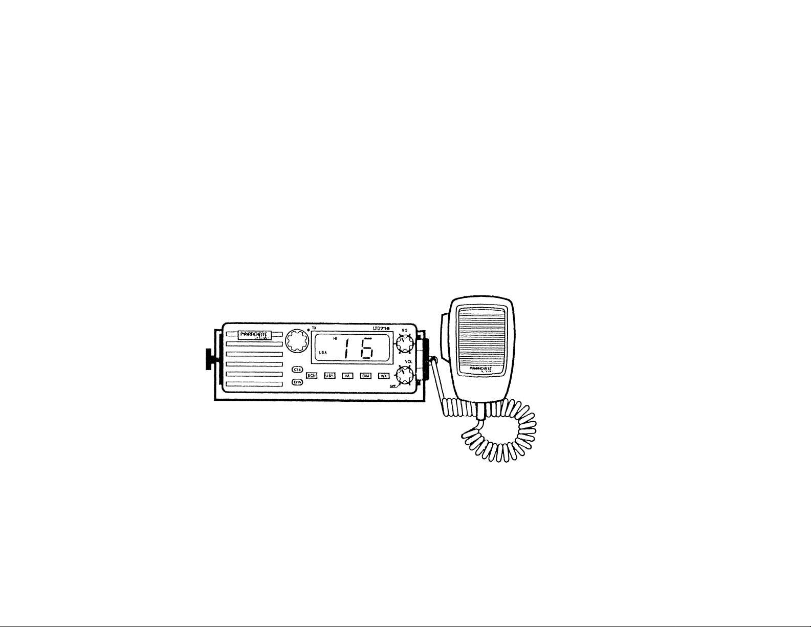
PRESIDENT LTD 715
Installation................................................................................................ 2
Choosing A Location
Engine Noise Suppression.................................................................... 3
Antenna Considerations.........................................................................3
Installing the LTD 715
Controls and Indicators............................................................................ 4
Front Panel Controls...............................................................................4
Front Panel Indicators
Rear Panel Connectors..........................................................................6
Operation.................................................................................................. 7
Dual V'/atch.............................................................................................7
Manual Tuning........................................................................................7
Timed Scan (SEEK)................................................................................7
Normal Scan tSCAN)..............................................................................8
Weather Scan......................................................................................... 8
Instant Channel 16 Communications......................................................8
US/International Channels......................................................................9
Transmitting............................................................................................ 9
Dimming the LCD Display Backlight and theTX Indicator
................................................................................
..............................................................................
............................................................................
............................................................................
....................
10
PRESIDENT LTD 715
The PRESIDENT LTD 715 VHP marine radio transceiver has been
1
2
3
5
designed to give you a rugged, reliable instrument that will provide you
with years of trouble-free service.
With proper care and maintenance, your PRESIDENT LTD 715 will
outlast your present vessel and serve you well on-board several more.
The full features and flexibility designed into this quality transceiver will
prevent it from becoming obsolete regardless of changes in craft or
geographic locations.
The technical excellence of the PRESIDENT LTD 715 is demonstrated
by the multiplicity of uses for which it has been found acceptable by the
U.S. Federal Communications Commission. The PRESIDENT LTD 715
is acceptable for compulsoiy use on “party boats," for use on vessels
subject to the Great Lakes Radio Agreement or bridge-to-bridge
requirements, for general pleasure and commercial vessels, and certain
land stations in marine service.
The PRESIDENT LTD 715 is of all solid state design with conservatively
rated rugged components and materials compatible with the marine
environment. The transceiver utilizes a number of gaskets, sealing rings,
waterproof membranes, and other sealants to effect a splashproof
housing for protection of the electronics. The unit may be mounted in
any number of convenient locations on your vessel by utilizing the
universal mounting bracket.
You are encouraged to thoroughly read the rest of this Operating Guide
to acquaint yourself with the characteristics and operation of your
transceiver so that you can contribute to the longevity of your investment.
Be sure to complete the Product Registration Card at the back of this
Guide, cut it out and mail it. You also need to complete the enclosed
Warranty Registration Card and mail it.
Channels and Functions (Table)
Specifications...........................................................................................13
Maritime Radio Services Operation.........................................................14
Care and Maintenance........................................................................... 15
Service.....................................................................................................16
...........................................................
11
Keep your receipt as proof-of-purchase in case warranty service is
required.
PRESIDENT is a trademark of Uniden America Corporation.
1
Page 3

INSTALLATION
CAUTION: The LTD 715 will operate only with nominal 12 volt
negative ground battery systems.
It is important to carefully determine the most suitable location for your
LTD 715 on your vessel. Electrical, mechanical, and environmental
considerations must all be taken into account. You must select the
optimum relationship among these considerations.
ENGINE NOISE SUPPRESSION
Interference from the impulse noise generated by the electrical systems
of engines is sometimes a problem with radios. The LTD 715 has been
designed to be essentially impervious to ignition impulse noise and
alternator noise. However, in some installations it may be necessary to
lake measures to further reduce the effect of noise interference. Ail DC
battery wires, antenna lead, and accessory cables should be routed away
from the engine and engine compartment, and from power cabling
carrying particularly high currents.
Keep in mind the flexibility designed into the LTD 715 so that you can
most convenientiy use your radio. Features which should be considered
are:
1. The universal mounting bracket may be installed on either the lop or
bottom of a sheif, on a bulkhead, or for overhead mounting.
2. The REMOTE speaker jack can be used with an auxiiiary speaker.
3. All connections are “piug-in" type for easy removal of the radio.
CHOOSING A LOCATION
Some important factors to consider in seiecting the iocation for your
LTD 715 .
1. Seiect a location that is free from spray and splash.
2. Keep the battery leads as short as possible. Direct connection to
the battery is most desirable. If direct connection cannot be made
with the supplied power lead, any extension should be made with
ff 10 AWG wire. Long extensions should use larger gauge wire.
3. Keep the antenna lead as short as possible. Long anteniia leads
can cause substantial loss of performance for botn receiving and
transmitting.
4. Locate your antenna as high as possible and clear from metal
objects. The reliable range of coverage is a direct function of
antenna height.
5. Select a location that does not allow the radio to be subjected to
direct sunlight (including that coming through windows).
6. Select a location that allows free air flow around the heal sink on the
rear of the radio.
7. Select a location well away from the ship’s compass. Auxiliary
speakers also should be located away from the compass.
In severe cases of impulse noise interference, it may be necessary to
install a noise suppression kit. Contact your PRESIDENT Dealer for
more information.
ANTENNA CONSIDERATIONS
A variety of antennas is available from a number of quality suppliers, it is
recomrnended you draw upon the advice of your PRESIDENT Dealer in
determining a suitable antenna for your vessel and range requirements.
In general, communication range is increased by using a high-gain
antenna placed as high as possible above the water line. Antennas
should be located away from metal objects. Antennas should not have
excessively long coaxial feed cables.
INSTALLING THE LTD 715
After you have carefully considered the various factors affecting your
choice of location, position the radio (with the bracket, microphone,
power cord, antenna and any auxiliary cables installed) into the selected
location to assure there is no interference with the surrounding items.
Mark the location of the mounting bracket. Remove the bracket from the
radio and use it as a template to mark the holes to be drilled for the
mounting hardware. Drill the holes and mount the bracket with hardware
compatible with the material of the mounting surface.
Connect the red wire of the supplied power cord to the positive (+) battery
supply. Connect the black wire of the power cord to ground. The power
cord is equipped with a fuse to protect the radio. Use only a Six (6)
AMPERE fast blow fuse for replacement. Connect the power cord to the
keyed connector on the power "pigtail" (See page 6).
Connect the antenna and all other auxiliary cables and accessories.
Install the radio in the mounting bracket and connect ail cables and
accessories to the appropriate jacks and connectors.
Page 4

CONTROLS AND INDICATORS
NOTE: For details of use of these Controls, see the OPERATION
section
FRONT PANEL
CONTROLS
12
1. VOL (On/OffA/olume) - Turns the LTD 715 power On or Off and
varies the audio ouput.
8. C16 (Channel 16) - Controls access to instant Channel 16
communications.
9. Rotary Channel Selector - This control is used to manually select
the desired Communication Channel (01 - 28 and 60 - 88), or
Weather Channel (0 - 5).
10. LCD Panel - Indicators for DUAL, SEEK, SCAN, USA, INT’L, HI,
LO, WX, and Channel Number.
NOTE: Refer to “INDICATORS" for detailed indicator descriptions.
11. SQ (Squelch) - Eliminates the background noise when no signal is
being received.
12. Press-To-Talk Switch - Press to transmit; release to receive.
INDICATORS
18 19 2021
22
2. WX (Weather) - Used to scan only Weather Channels 0 - 9.
3. DIM - This control is used to adjust the brightness of the LCD Panel
backlight, and the brightness of the TX indicator. The LCD Panel
backiight and TX indicator are at the brightest level when the LTD
715 is turned on.
4. H/L (Migh/Lovv) - Controls transmitter output power f25 Waft, where
allowed, or 1 Walt). The output power is 25 Watts wnen the LTD
715 is turned on.
5. US/1 (United States/International) - Switches operation between
US and International Channels.
6. SCN (Scant - Used to start timed Scan (SEEK), switch to standard
Scan (SCAN), and to resume scanning when stopped on a Channel.
7. DAN (Dual Watch) - Turns Dual Watch On/Off.
13. LCD Numerical Channel Display - Indicates Channel Number in
use. Weather Channels are displayed as single digits. (Example: 0,
1,2, 3, etc.) Communication Channels are displayed as two digits
(Example: 01,02, 03, etc.),
NOTE: LCD Status Indicators appear when status is selected by
pressing the corresponding button.
14. INT’L (International) - Indicates International Channel Mode.
15. USA - Indicates US Channel Mode.
16. SCAN - Indicates Normal Scan Mode.
17. SEEK - Indicates Timed Scan Mode on Communication Channels.
Page 5

18 19 2021
OPERATION
18. TX (Transmit) - LED lights when transmitting,
19. DUAL (Dual Watch) - Indicates Dual Watch Mode.
20. HI (High) - Indicates transmitted output is 25 Watts.
21. LO (Low) - Indicates transmitted output is 1 Watt.
22. WX (Weather) - Indicates Weather Channels.
REAR PANEL CONNECTORS
22
1. Turn the unit On by rotating the VOL control clockwise.
2. Adjust the SQ control counterclockwise until you hear background
noise; then turn it clockwise until the noise just disappears.
DUAL WATCH
Dual Watch monitors Channel 16 for activity every two seconds while
scanning or monitoring.
To activate Dual Watch, Press DA/V while in any mode. The DUAL
indicator will appear on the LCD Panel, indicating Dual Watch Mode. If a
signal is received on Channel 16, the radio remains on Channel 16 until
the signal ends.
Press D/W again to cancel Dual Watch Mode.
MANUAL TUNING
To manually select a channel, rotate the Rotary Channel Selector to the
desired channel. Weather Channels are located on Channels 0 - 9.
Communication Channels are located on Channels 01 - 28 and 60 - 88.
TIMED SCAN (SEEK)
Press SCN to start SEEK (Timed Scan).
23. Remote Speaker Connector - An external 4 ohm, 4 watt speaker
may be connected to this jack. The connecting wire must have a
miniature plug.
24. Antenna Connector - Connect the antenna here using a type
PL259 connector.
25. DC Power "Pigtail" and Connector - Connect supplied power cord
to the keyed connector.
When SCN is pressed for the first time after the LTD 715 is turned on,
scanning will be in the SEEK (Timed Scan) Mode, and SEEK and DUAL
will display on the LCD Panel.
The radio scans for active Communication Channels except for Channel
16. (CH 16 is not included in the Scan cycle.)
Notice that Dual Watch is on automatically to cover CH 16 as well.
If there is too much activity on CH 16, and you vdsh to exclude it from
SEEK, Press D/W to cancel Dual Watch. (DUAL no longer displays on
the LCD Panel.)
In SEEK, the radio stops on the first active channel and stays on for 4
(four) seconds, then resumes Timed Scanning to the next active channel.
Page 6

NORMAL SCAN (SCAN)
Press and Hold SCN until SEEK goes off and SCAN displays on the
LCD Panel This changes the scanning from Timed Scan to Normal
Scan.
In Normal Scan, the radio will stop on the first active channel and stay
until the signal i.s gone, or SCN is pressed to resume scanning.
Notice that Dual Watch is on automatically to cover CH 16 as well.
To cancel Channel 16 communications:
• Press C16, or
• Press SCN, or
• Press WX, or
• turn the Rotary Channel Selector.
NOTE: D/W, US/I, H/L and DIM work without interrupting Channei 16
Mode.
If there is too much activity on CH 16, and you wish to exclude it from
SEEK, Press DAV to cancel Dual Watch. (DUAL no longer displays on
the LCD Panel.)
To cancel scanning:
• Press Press-To-Talk, or
• Press C16, or
• turn the Rotary Channel Selector, or
• turn the power off.
NOTE: D/W, US/I, DIM and H/L work without interrupting the Scanning
Mode.
WEATHER SCAN
To scan only Weather Channels 0-9, Press WX. The WX indicator will
appear on the LCD Panel, indicating V'/eather Mode. Timed Scan
(SEEK) will not function in Weather Mode,
Press SCN to switch to Timed Scanning of Communication Channels, or
Press and Hold SCN until SCAN appears on the LCD Panel, or Normal
Scanning of Communication Channels.
INSTANT CHANNEL 16 COMMUNICATIONS
To access instant Channel 16 communications, Press Cl 6. This
overrides the channel selected with the Rotary Channel Selector. The
Channel Display will indicate the unit is on Channel 16. Press C16
again to release the switch (Off) and the transceiver will return to the
channel selected prior to accessing instant Channel 16 communications.
The Channel Display will indicate the selected channel.
US/INTERNATIONAL CHANNELS
To select operation (communication and scanning) on US Channels,
Press US/I. USA will appear on the LCD Panel.
To select operation (communication and scanning) on International
Channels, Press US/I. INT’L will appear on the LCD Panel.
TRANSMITTING
When the power is turned on, the transmitter is set for 25 Watts (except
for USA channels 13 and 67). The HI indicator will appear on the LCD
Panel, indicating 25 Watt output power. In order to comply with FCC
Regulations contained in 47 CFR 80.215 (g) (3), USA Channels 13 and
67 transmit at 1 Watt regardless of the H/L selector setting. However, 25
Watt output for emergency use is available by pressing H/L while
pressing the Press-To-Talk switch. When the H/L switch is released, the
radio returns to the 1 Watt position.
To switch to the LO (1 Watt) position. Press H/L. The LO indicator will
appear on the LCD Panel, indicating 1 Watt output power. The LO
position should always be used for in-port or short range communications.
Press H/L to switch to the HI (25 Watt) position. The HI indicator will
appear on the LCD Panel, indicating 25 Watt output power.
To activate the transmitter. Press the Press-To-Talk switch on the
microphone. The TX LED indicator will light, indicating a signal is being
transmitted. Release the switch to receive. When transmitting, hold the
microphone approximately two inches from your mouth and speak clearly
in a normal voice. The microphone provided with your radio is a 500 ohm
dynamic type.
NOTE: You cannot transmit on Weather Channels 0-9 or Channel 15.
The Channel Number in' the LCD Panel will blink to indicate
these channels are "receive-only".
Page 7

DIMMING THE LCD DISPLAY BACKLIGHT AND THE TX
INDICATOR
When the LTD 715 is turned on, the LCD Panel and TX LED will be
brightest. Successive presses of the DIM button will change the
brightness.
LCD Panel
ГХ Indicator
Note that the TX LED is not turned Off by the DIM button.
OPTIONAL ACCESSORIES
Flush mounting bracket for "in dash" installation.
Contact your President Marine Dealer for information.
VHP FM MARINE RADIOTELEPHONE
CHANNELS AND FUNCTIONS
(U.S.A. CHANNELS)
CHANNEL
DESIO
wxo 163,275
WX1
WX2
WX3
WX4
WX5 162,450
WX6 162,500
WX7 162.525
WX8
WX9
01
02
03
04
05 156,250
06 156,300
07
08
09
10 156,500 156,500
11
12
13 156,650
14
15
16
17
18 156,900
19
20
21
22
23 157,150 157,150
24
25 157,250 161,850
26
27
28
60
61 156,075
62 156,125
63
64
65
66
67
68
69
70
71
72
73 156,675
74 156,725
77 156,875 156,875 Port Ops
78
79
80
81
82 157.125
83
84
85
86
87
88
FREQUENCY (MHz)
TRANSMIT
156,050 156,050
156,100
156.150
156,200 156,200
156,350
156,400
156.450
156,550
156,600
156,700
156,800
156,650 156,850 State Control
156.950
157 000
157.050 157 050
157,100
157,200
157.300
157.350
157,400
156,025 156,025
156,175 156,175
156.225 156,225
156,275
156,325
156,375
156,425 156,425
156,475 156,475
156,525
156,575
156,625 156,625 Non Com'l Yes No
156,925
156,975 156,975
157,025
157.075 157.075 Coast Guard
157,175
157,225
157,275 161.875
157,325 161,925
157,375 161,975
157,425
RECEIVE
162 550
162,400
162.475
162,425
161,650 Can Weather
161,775
156,100
156,150
156,250
156,300
156,350
156,400
156,450 Com 1 & Non Com'l
156,550
156,600
156.650 Navigational
156,700 Port Ops
156.750
156.800 Safety Calling Yes Yes
156,900 Com'l
156,950
161.600
157,100 Coast Guard Yes Yes
161,800 Public Corresp
161,900 Public Corresp
161,950
162.000
156,075
156,125
156,275
156,325
156,375
156,525
156,575
156,675
156,725
156,925
157.025
157.125
157,175
161,825 Pubifc Corresp
157.425
NOAA Weather
NOAA Weather ПХ Only RX Only
NOAA Weather RX Only RX Only
NOAA Weather
NOAA Weather RX Only
NOAA Weather
NOAA Weather
NOAA Weather
Can Weather RX Only RX Only
VTS Yes
Port Ops Yes Yes
Port Ops
Port Ops
VTS
Safety
Com'l
Corn!
Com’l
Com'l
Port Ops
Environmental
Com’l Yes Yes
Port Ops
Coast Guard Yes
Coast Guard
Public Corresp
Public Corresp No
Public Corresp
Port Ops
Port Ops
Com'l
Non Com !
Non Com'l
Non Com'l
Non Com’l
Port Ops
Port Ops
Non Com’l
Com'l
Com)
US Govt Only
Coast Guard
Public Corresp
Public Corresp No
Public Corresp No
Com'l
TYPE OF
TRAFFIC
SHIP
TO SHIP
RX Only
RX Only
RXOnly RX Only
RX Only RX Only
RX Only
RX Only
Yes
Yes
Yes Yes
Yes No
Yes
Yes No
Yes Yes
Yes
Yes Yes
Yes
Yes Yes
Yes
RX Only
Yes Yes
Yes Yes
Yes Yes
Yes Yes
No
No
No
No
Yes
Yes Yes
Yes No
Yes Yes
Yes Yes
Yes
Yes
Yes
Yes
Yes
Yes
Yes
Yes
Yes
Yes Yes
Yes Yes
No
No
Yes
SHIP
TO SHORE
RX Only
RX Only
RX Only
RX Only
RXOnly
Yes
Yes
Yes
Yes
Yes
Yes
Yes
RX Only
Yes
Yes Busy Tel,
Yes
Yes
Yes
Yes .
Yes
No
Yes
Yes
Yes
No
Yes
Yes
Yes
Yes
Yes Busy Tel.
Yes Busy Tel.
Yes
Yes
No
PERMANENT
SCAN LIST
Weather
Weather
Weather
V/eat her
Weather
Weather
Weather
Weather
Weather
Weather
Coast Guard
Pish
Environrrtental
Coast Guard
Coast Guard
Coast Guard
Busy Tel.
Busy Tel.
Busy Tel,
Busy Tel,
pish
Fish
Pish
Fish
Fish
Coast Guard
Coast Guard
Busy Tel.
Busy Tel,
10
11
Page 8

VHF FM MARINE RADIOTELEPHONE CHANNELS
AND FUNCTIONS
(INTERNATIONAL CHANNELS)
CHANNEL
DESIO
wxo
WXl
WX2
VVX3
WX4
WX5
VVX6
WX7
wxa
WX9
01
02
03
СЛ
05
C6
07
06
CQ
10
1 1
12
13
14
15
16
17
18
19
20
21
22
23
24
25
26
27
28
60
61
62
S3
64
65
66
67
68
69
70
71
72
73
74
77
78
79
80
81
82
83
84
85
86
87
88
FREQUENCY (MHz)
TRANSMIT RECEIVE
156 050
156 100
156 150 160 750
156 200
156 250
156 300
156 350 160 950
156 400
156 450
156 500 156 500
156 550
156 600 156 600
156 650 156 650
156 700 156 700
156 750
156 800
156 850 156 850
156 900
156 950
157 000 161 600
157 050 161 650
157 100 161 700
157 ISO 161 750
157 200
157 250 161 850
157 300 161 900
157 350
157 400
156 025
156 075
156 125
156 175
156 225 160 825
'156 275
156 325
156 375 156 375
156 425 156 425
156 475 156 475
156 525 156 525
156 575
156 625
156 675 156 675
156 725
156 875
156 925
156 975 161 575
157 025 161 625
157 075
157 125
157 175
157 225
157 275
157 325
157 375
157 425
163 275
162 550
162 400
162 475
162 425
162 450
162 500
162 525
161 650
161 775
160 650
160 700
160 800
160 850
156 300
156 400
156 450
156 550
156 750
156 300
161.500
161 550
161 800
161 950
162 000
160 625
160 675
160 725
160 775
160 875
160 925
156 575
156 625
156 725
156 875
161 525
161 675
161 725
161,775
161 825
161,875
161 925
161 975
162.025
TYPE OF
TRAFFIC
NO.AA Weather
NOAA Weather
NOAA Weather
NOAA Weather
NOAA Weather
NOAA Weather
NOAA Weather
NOAA Weather
Can Weather
Can Weather
VTS
Port Ops
Port Ops
Pori Ops
VTS
Safety
Com'l
Corn!
Com'l 8 Non Com'l
Com'l
Com! Yes
Port Ops Yes
Navigational
Port Ops Yes
Environmental Yes Yes
Safety Calling
State Control Yes Yes
Com 1
Com!
Port Ops
Coast Guard
Coast Guard
Coast Guard
Public Corresp
Public Corresp
Public Corresp
Public Corresp
Public Corresp No
Port Ops
Por1 Ops
Com'l Yes
Non Com'l
Non Com'l
Non Com'l
Non Com'l Yes
Non Com'l Yes
Port Ops Yes Yes
Port Ops Yes
Port Ops
Non Com'l Yes Yes
Com'l Yes
Corn!
Coast Guard
US Govt Only
Coast Guard Yes Yes
Public Corresp No
Public Corresp
Public Corresp
Public Corresp
Com'l
SHIP
TO SHIP
RX Only
RX Only
RX Only
RX Only RX Only
RX Only RX Only
RX Only RX Only
RX Only RX Only
RX Only RX Only Weather
RX Only
RX Only
Yes
Yes Yes
Yes Yes
Yes Yes
Yes
Yes No
Yes
Yes
Yes Yes Fish
Yes Yes
Yes Yes
Yes Yes
Yes Yes
Yes Yes
Yes Yes
Yes
Yes
Yes
No
No Yes Busy Tel.
No Yes
No Yes Busy Tel.
Yes
Yes Yes
Yes
Yes
No No
Yes No
Yes Yes
Yes Yes
Yes Yes
No
No
No
Yes
TO SHORE
RX Only
RX Only
RX Only Weather
RX Only Weather
RX Only
Yes
Yes
Yes
No
Yes
Yes
Yes
Yes
Yes
Yes
Yes
Yes
Yes
No
Yes Fish
Yes Fish
Yes
No Fish
Yes
Yes
Yes
Yes
Yes
Yes
No
SHIP
PERMANENT
SCAN LIST
Weather
Weather
Weather
Weather
Weather
Weather
Weather
Environmental
Busy Tel.
Busy Tel
Busy Tel.
Fish
Fish
Coast Guard
Coast Guard
Busy Tel.
Busy Tel.
Busy Tel.
Busy Tel.
Busy Tel.
SPECIFICATIONS
GENERAL
Channels
Controls
Status Indicators
Channel Display
Selector Switch
Buttons
Connectors
Size
Weight
Supply Voltage
Standard Accessories
Antenna impedance
Microphone
Speaker
Operating Temperature Range
Shock and Vibration
FCC Approvals
TRANSMITTER
Power Output
Power Requirement
Modulation
Hum and Noise
Signal-to-Noise
Audio Distortion
Spurious Supression
Output Power Stabilization
Transmit 55
Receive 80 Marine
10 Weather
On-OffA/olume, Squelch
TX LED (transmit), DUAL. SEEK, SCAN,
USA, INTL, HI, LO, and WX on LCD
Panel
LCD (Dual 7 segment)
Rotary Channel Selector
H/L (25W/1W power), DIM, US/I, WX,
DAV. SCN, C16
Antenna, remote speaker and DC power
2 1/5"Hx6 2/5”Wx8"L
2.4 lbs
13.8V DC negative ground
Mounting bracket and hardware, DC
power cord, microphone hanger, spare
fuse
son, nominal
Rugged 5000 dynamic element with
coiled cord
1.82 inch, 80
-20°C to +50°C (-4®F to +122T)
Meets or exceeds EIA standards,
RS152B and RS204C
Type accepted under part 80 of the Rules;
meets Great Lakes Agreement and party
boat requirements
1 watt or 25 watt (sv/itch selectable)
1 watt output: 1.0A at 13.8V DC 25 watts
output: 4.5A at 13.8V DC
FM ±5 kHz deviation (FCC designator
F3E)
45 dB at 3 kHZ
Less than 5% with 3 kHz deviation with
1000 Hz modulating frequency
-60 dB at 1 watt, -65 dB at 25 watts
Built-in automatic level control (ALC)
12
13
Page 9

Frequency Range
Frequency Stability:
156 to 158 MHz
±300 Hz nominal
RECEIVER
Frequency Range
Sensitivity
Circuit
Squelch Sensitivity
Spurious Response
Adjacent Channel Selectivity
Audio Output Power
Power Requirement
156 to 163 MHz
0.25pV for 12dBSINAD
0.35pV for 20 dB S/N
Dual Conversion Super Heterodyne PLL
0.5pv Threshold
60 dB
70 dB at ±25 kHz
4.0 watts (10% Distortion)
0.2A at 13.8V DC squelched
0.9A at 13.8V DC at maximum audio
output
1st - 16.9 MHz
2nd - 455 kHz
MARITIME RADIO SERVICES OPERATION
You are required to comply with the Rules and Regulations as set forth
by the Federal Communications Commission. A complete set of FCC
Marine Radio Rules may be purchased from the US Government Printing
Office by requesting “Volume IV of the FCC Rules,” Among the more
significant rules are:
You may not make transmitter tuning adjustments unless you are
the holder of a valid first or second class commercial license issued
by the FCC. Please request the assistance of your PRESIDENT
Marine Dealer and your nearest FCC Field Office if you need other
than a Ship’s Station License.
__________
CARE AND MAINTENANCE
__________
Your LTD 715 is a precision piece of electronic equipment and you
should treat it accordingly. Due to the rugged design, very little
maintenance is required. However, a few precautions should be
observed:
• If your radio has been accidentally subjected to spray or splash, you
should immediately wipe it down with a soft cloth dampened with fresh
water.
• If the antenna has been damaged, you should not transmit except in
case of emergency. A defective antenna may cause damage to your
radio.
• You are responsible for the continued FCC technical compliance of
your radio.
• You are urged to arrange for periodic performance checks with your
PRESIDENT Marine Dealer.
1. You must obtain a Ship’s Station License by making application to
the FCC on FCC Form 506. An Interim Ship’s Station License may
be obtained by personal appearance at your local FCC Field Office.
The Ship's Station License must be posted at the station location.
2. A Restricted Radiotelephone Operator Permit (or higher grade
license) must also be obtained from the FCC in order to legally
operate your transmitter in international waters. Application is to be
made on FCC Form 753, An interim permit is automatically granted
upon submission of your application.
3. You must keep a current copy of the appropriate FCC Rules.
4. You must maintain a log book in which you record all calls and full
transmitter maintenance records.
5. Your transmitter must be verified, by an appropriately licensed
technician, to be in compliance with FCC requirements. This has
been done at the factory for your LTD 715. A signed Certificate of
Compliance card is included with your radio and should be kept with
your log book.
14
15
 Loading...