

Uniden LTD260 Owner's Manual

LTD260
DIGITAL DEPTH LOG
LTD260.qxd 12/15/98 8:24 AM Page 1
Digital Depth Sounder
LTD 260
TO OUR CUSTOMER:
We would like to extend our thanks to you for purchasing the LTD 260.This product is a
highly sophisticated instrument which is designed using the criteria “simplicity of operation”.
It is very important that you review this manual carefully and thoroughly prior to using your
President instrument. Successful instr ument operation can be achieved with proper
installation, background education, and a thorough understanding of how the equipment
operates.
Your LTD 260 is an aid to navigation and does not reduce the need for caution or judgment.
No electronic navigation system is absolutely reliable; outputs may occasionally be incorrect.
The careful navigator should never rely solely on one device, to the extent of endangering life
or property.Please remember that any time a display reading flashes on and off, the outputs
may be in error and should not be used for navigation.We recommend that you use this
system in combination with marine charts, and knowledge of the area where your are
boating.
Again, we want to thank you for purchasing a President product and are confident of your
satisfaction.
Sincerely,
PRESIDENT
PRESIDENT, 4700 Amon Car ter Blvd., Fort Worth, TX 76155, USA, Phone (817) 858-3300
2
LTD260.qxd 12/15/98 8:24 AM Page 2

This manual has been arranged in the sequence outlined below. This overview below will provide
you with a correct sequence of events required to successfully install and operate your
instrument.
DEPTH READINGS
The LTD 260 is designed to give depth readings from 2.5 feet to a maximum depth of 199 feet.
Depth readings are in 1/10 foot increments from 2.0 feet to 15 feet and then are shown as whole
numbers up to 199 feet.These readings are displayed on a large Liquid Crystal Display (LCD).
NIGHT VIEWING
The LTD 260 is back lit at all times with a soft glowing lamp designed to help your night time
navigational needs.
GENERAL OVERVIEW:
3
FEATURES:
INSTALLATION: WIRING . . . . . . . . . . . . . . . . . . . . . . . . . . . . . . . . . . . .4
INSTALLATION: LTD 260 . . . . . . . . . . . . . . . . . . . . . . . . . . . . . . . . . . . .4
GENERAL INFORMATION: DEPTH SOUNDER TRANSDUCER . . . . . . . . . . . . . . .5
INSTALLATION: POWER SOURCE . . . . . . . . . . . . . . . . . . . . . . . . . . . .5
INSTALLATION: DEPTH TRANSDUCERS . . . . . . . . . . . . . . . . . . . . . . .7
INSTALLATION: TRANSOM MOUNT TRANSDUCERS . . . . . . . . . . . . .8
INSTALLATION: THROUGH-THE-HULL TRANSDUCERS . . . . . . . . . . .9
INSTALLATION: POWERBOAT BRONZE TRANSDUCERS . . . . . . . . .10
INSTALLATION: INSIDE THE HULL TRANSDUCERS . . . . . . . . . . . . .11
OPERATION: How to set the alarm . . . . . . . . . . . . . . . . . . . . . . . . .12
GLOSSARY . . . . . . . . . . . . . . . . . . . . . . . . . . . . . . . . . . . . . . . . .13
TROUBLESHOOTING: GENERAL OPERATION . . . . . . . . . . . . . . . . . . . . . .14
TROUBLESHOOTING: SHALLOW WATER SENSITIVITY . . . . . . . . . . . . . . .15
CARE AND MAINTENANCE: . . . . . . . . . . . . . . . . . . . . . . . . . . . . . . . . . . . . . . . . .17
SPECIFICATIONS: . . . . . . . . . . . . . . . . . . . . . . . . . . . . . . . . . . . . . . . . .17
SPARE PARTS LIST: . . . . . . . . . . . . . . . . . . . . . . . . . . . . . . . . . . . . . . . . .17
APPENDIX PRESIDENT LIMITED WARRANTY . . . . . . . . . . . . . .18
APPENDIX OUT OF WARRANTY - FLAT RATE CHARGE . . . . . .19
LTD260.qxd 12/15/98 8:24 AM Page 3
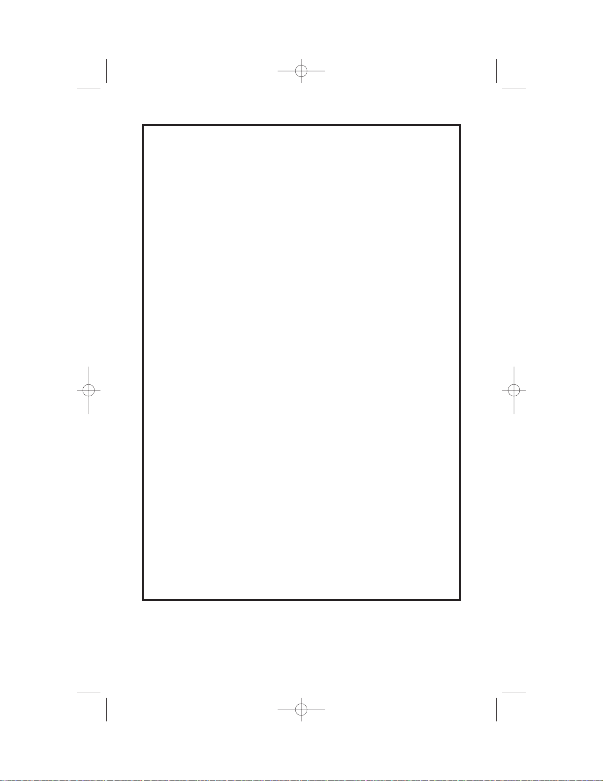
First, find a location on your dash panel which will give clear viewing and access to the LCD
window.After finding the right location for the indicator unit, mark a 2 in. hole to be cut out. Check
behind the panel for any cables or wiring which could be damaged and then cut out the 2 in.hole.
Test fit the unit in the hole and make any adjustments with our saw or drill. Extending out of the
back of the instrument, you will notice a brass shaft. First attach the U-shaped mounting bracket
over this shaft, place the washer on the shaft and then tighten the nut until the U-shaped bracket
presses tightly to the back of the dash panel.. Look at the front of the instrument to ensure that it
is aligned properly and then tighten securely.
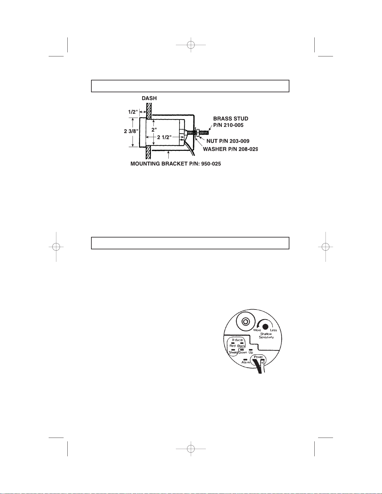
On the rear of the unit, locate the terminal lugs extending out of the rear of the instrument.These
terminal are used to connect the impeller wires.
When shipped from the factory, the transducer is wired with three female lugs attached that need
to be inserted into the male terminal located on the rear of the gauge. Exercise caution when
installing these connectors since improper wiring of the transducer to the wrong terminals can
cause internal damage to the instrument which could cause the unit to fail when power is applied.
BLACK=TRANSDUCER LOW
RED=TRANSDUCER HIGH
BARE SHIELD=BARE
Part Number=703-025
(Ter minals)
INSTALLATION: WIRING
INSTALLATION: LTD 260
4
LTD260.qxd 12/15/98 8:24 AM Page 4

BATTERY CONNECTION/POWER REQUIREMENT
Because the LTD 260 has no ON/OFF switch, you will need to wire it directly to a power source
which will turn the unit on as power is applied. It may be a power source which will turn the unit
on as power is applied. It may be convenient to wire the power cable directly to the Ignition Switch
so that when you turn the boat on, the depth sounder immediately starts working. Some boats
have already been prewired and labeled for a depth sounder so that when the switch is turned
ON, the depth sounder receives power.
1. Connect the main unit to a 12 volt battery using the power cable supplied with your unit. You
may extend this cable as necessary, but you must observe proper polarity (i.E., red is
positive, black is negative).
2. Connect the BLACK wire to the negative (-) battery terminal.
3. Connect the RED wire to the positive (+) battery terminal.
4. Make sure the connections are clean and tight so they do not vibrate loose during the boat’s
operation. Occasionally clean any accumulated corrosion from the battery terminals.
5. If for some reason the fuse is blown, replace with a 1 amp fuse, normal blow.
DO NOT OVER FUSE! Because the unit consumes .25 amps of current when it is on, you will
want to keep your battery fully charged.
UNDERSTANDING SONAR:
All depth sounders emit Ultra Sonic Sound signals by a transducer into the water located under
your boat.These sound signals travel through the water at a rate of 4,800 feet per second.The
depth sounder transmits a signal and receives a returning echo.The unit calculates the amount of
time in microseconds for the signal to travel to the bottom and return back to the transducer.It
then converts this time into depth and displays it on the screen.
It may help to imagine these sound signals bouncing up and down from the transducer to the
bottom by comparing it to a ping pong ball bouncing up and down from the floor.The closer the
ball is to the floor, the less time it takes for it to retur n. The higher the ball is bounced, the longer
time it takes for it to return. Bouncing a ball off a hard surface such as cement is the same as
bouncing a signal off a sandy or hard bottom. Bouncing this same ball off carpeting creates a
totally different effect.The ball (echo) returns with less force (weaker echo).The same analogy
applies to an echo bouncing on a muddy or grassy bottom - the echoes are weaker.
GENERAL INFORMATION: DEPTH SOUNDER TRANSDUCER
INSTALLATION: POWER SOURCE
5
LTD260.qxd 12/15/98 8:24 AM Page 5

AIR ECHOES:
Air echoes can be caused by too much turbulence under the face of the transducer.It is important
to know that ultra sonic signals from a transducer will not penetrate air. They react to air in the
same manner as they react to a hard bottom described above.Therefore, if your transducer is not
mounted properly and you are getting turbulence (air bubbles) under your transducer, you may
get false readings simply because signals are being returned by the turbulence and never
reaching the bottom.
Adjusting the Shallow Water sensitivity can reduce this problem.Adjustment of the transducer
location can also help solve these false readings.
TRANSDUCER REPLACEMENT/IDENTIFICATION TAG
On most transducers manufactured after 1987, the operating frequency and part number is
attached to the cable or is printed on a mylar tag near the connector end. Do not remove this tag
since it identifies the transducer and will help you identify the operating frequency of the
transducer.(Improper frequency will cause your instrument to not operate properly.) Removal of
the identification tag will void the warranty.
SALTWATER MAINTENANCE/ANTIFOULING PAINT
Antifouling Paint:If the vessel is kept in saltwater, sea growth can accumulate rapidly on the
transducer face and seriously reduce performance in a matter of weeks.If fouling does occur, use
a stiff brush or putty knife to remove this growth.Wet sanding of the fouled transducer face is
permissible with #220 or finer grade of wet or dry emery paper. (Use plenty of water.) Coating
transducers with antifouling paint is often necessary to achieve consistent perfor mance. All anti
fouling paints have a solvent base and solvents attack encapsulation materials and plastics to
varying degrees. If you need anti fouling protection use only paints with a mineral spirits base; do
not use acetone vinyl based paints. Glouchester (RULE) 7 is a hard, mineral spirits based paint
that we have found to be practically transparent to acoustic energy. Never apply paint to the
transducer by spraying;use a brush or roller.A sprayed surface “wets” very slowly and there are
often microscopic air pockets under the surface which attenuate the sound energy.
6
LTD260.qxd 12/15/98 8:24 AM Page 6
 Loading...