

Uniden GNVR 49xxW, GNVR 167 Series, GNVR 8640, GNVR 8680, GNVR 8740 Owner's Manual

GNVR 49xxW
Wireless Network Video Recorder
Security System
OWNER’S MANUAL
For more exciting new products please visit our website:
Australia: www.uniden.com.au
WARNING
RISK OF ELECTRICAL SHOCK
DO NOT OPEN
WARNING: TO REDUCE THE RISK OF ELECTRIC SHOCK, DO NOT
REMOVE COVER. NO USER SERVICEABLE PARTS INSIDE.
REFER SERVICING TO QUALIFIED SERVICE PERSONNEL.
The exclamation point within an equilateral triangle is intended to alert the user
to the presence of important operating and maintenance (servicing) instructions
in the literature accompanying the appliance.
The lightning flash with arrowhead symbol, within an equilateral triangle, is
intended to alert the user to the presence of uninsulated “dangerous voltage”
within the product’s enclosure that may be of sufficient magnitude to constitute
a risk of electric shock.
WARNING: TO PREVENT FIRE OR SHOCK HAZARD
DO NOT EXPOSE THIS UNIT TO RAIN OR MOISTURE.
In addition to the careful attention devoted to quality standards in the
manufacturing process of your product, safety is a major factor in the design of
every instrument. However, safety is your responsibility too. This section lists
important information that will help to ensure your enjoyment and proper use
of the product and accessory equipment. Please read them carefully before
operating and using your product.
IMPORTANT SAFEGUARDS

GENERAL PRECAUTIONS
1. All warnings and instructions in this manual should be followed.
2. Remove the plug from the outlet before cleaning. Do not use liquid aerosol
detergents. Use a water-dampened cloth for cleaning.
3. Do not use this product in humid or wet places.
4. Keep enough space around the product for ventilation. Slots and openings
in the storage cabinet should not be blocked.
5. It is highly recommended to connect the product to a surge protector to
protect from damage caused by electrical surges. It is also recommended
to connect the product to an uninterruptible power supply (UPS), which
has an internal battery that will keep the product running in the event of a
power outage.

1. Read and Follow Instructions - All the safety and operating instructions
should be read before the product is set up and used. Follow all operating
instructions.
2. Retain Instructions - These safety and operating instructions should be
retained for future reference.
3. Heed Warnings - Comply with all warnings on the product and in the
operating instructions.
4. Power Sources - This product should be operated only from the type of
power source indicated on the marking label. If you are not sure of the type
of power supplied to your location, consult your video dealer or local power
company. For products intended to operate from battery power or other
sources, refer to the operating instructions.
5. Overloading - Do not overload wall outlets or extension cords as this can
result in the risk of fire or electric shock. Overloaded AC outlets, extension
cords, frayed power cords, damaged or cracked wire insulation, and
broken plugs are dangerous. They may result in a shock or fire hazard.
Periodically examine the cord, and if its appearance indicates damage or
deteriorated insulation, have it replaced by your service technician.
6. Power-Cord Protection - Power supply cords should be routed so that
they are not likely to be walked on or pinched by items placed upon or
against them. Pay particular attention to cords at plugs, convenience
receptacles, and the point where they exit from the product.
7. Surge Protectors - It is highly recommended that the product be connected
to a surge protector. Doing so will protect the product from damage caused
by power surges.
8. Uninterruptible Power Supplies (UPS) - As this product is designed
for continuous, 24/7 operation, it is recommended that you connect the
product to an uninterruptible power supply. An uninterruptible power
supply has an internal battery that will keep the product running in the
event of a power outage.
9. Ventilation - Slots and openings in the case are provided for ventilation to
ensure reliable operation of the product and to protect it from overheating.
These openings must not be blocked or covered. The openings should
never be blocked by placing the product on a bed, sofa, rug, or other similar
surface. This product should never be placed near or over a radiator or
heat register. This product should not be placed in a built-in installation
such as a bookcase or rack unless proper ventilation is provided and the
product manufacturer’s instructions have been followed.
INSTRUCTIONS

10. Water and Moisture - Do not use this product near water - for example,
near a bath tub, wash bowl, kitchen sink or laundry tub, in a wet basement,
near a swimming pool, etc.
11. Heat - The product should be situated away from heat sources such as
radiators, heat registers, stoves, or other products (including amplifiers)
that produce heat.
12. Accessories - Do not place this product on an unstable cart, stand, tripod,
or table. The product may fall, causing serious damage to the product. Use
this product only with a cart, stand, tripod, bracket, or table recommended
by the manufacturer or sold with the product. Any mounting of the
product should follow the manufacturer’s instructions and use a mounting
accessory recommended by the manufacturer.
13. Camera Extension Cables - Check the rating of your extension cable(s) to
verify compliance with your local authority regulations prior to installation.
14. Mounting - The cameras provided with this system should be mounted
only as instructed in this guide or the instructions that came with your
cameras, using the provided mounting brackets.
15. Camera Installation - Cameras are not intended for submersion in
water. Not all cameras can be installed outdoors. Check your camera
environmental rating to confirm if they can be installed outdoors. When
installing cameras outdoors, installation in a sheltered area is required.
SERVICE
1. Servicing - Do not attempt to service this product yourself, as opening or
removing covers may expose you to dangerous voltage or other hazards.
Refer all servicing to qualified service personnel.
2. Conditions Requiring Service - Unplug this product from the wall outlet
and refer servicing to qualified service personnel under the following
conditions:
• When the power supply cord or plug is damaged.
• If liquid has been spilled or objects have fallen into the product.
• If the product has been exposed to rain or water.
• If the product has been dropped or the cabinet has been damaged.
• If the product does not operate normally by following the operating
instructions. Adjust only those controls that are covered by the
operating instructions. Improper adjustment of other controls may
result in damage and will often require extensive work by a qualified
technician to restore the product to its nor mal operation.

6
• When the product exhibits a distinct change in performance. This
indicates a need for service.
3. Replacement Parts - When replacement parts are required, have the
service technician verify that the replacements used have the same safety
characteristics as the original parts. Use of replacements specified by the
product manufacturer can prevent fire, electric shock, or other hazards.
4. Safety Check - Upon completion of any service or repairs to this product,
ask the service technician to perform safety checks recommended by the
manufacturer to determine that the product is in safe operating condition.
USE
1. Cleaning - Unplug the product from the wall outlet before cleaning. Do
not use liq uid cleaners or aerosol cleaners. Use a damp cloth for cleaning.
2. Product and Cart Combination - When product is installed on a cart,
product and cart combination should be moved with care. Quick stops,
excessive force, and uneven surfaces may cause the product and cart
combination to overturn.
3. Object and Liquid Entry - Never push objects of any kind into this product
through openings as they may touch dangerous voltage points or “shortout” parts that could result in a fire or electric shock. Never spill liquid of
any kind on the product.
4. Lightning - For added protection of this product during a lightning storm,
or when it is left unattended and unused for long periods of time, unplug
it from the wall outlet and disconnect the antenna or cable system. This
will prevent damage to the product due to lightning and power line surges.

7
INTRODUCTION .............................................................................................. 9
WHAT’S IN THE BOX? ..................................................................................11
GETTING TO KNOW YOUR NVR ................................................................. 12
INSTALLATION..............................................................................................14
SETUP.............................................................................................................20
OPERATION ...................................................................................................23
LIVE VIEWING ........................................................................................... 23
PREVIEW CONTROL ................................................................................ 24
SHORTCUT MENU .................................................................................... 26
USB DEVICE AUTO POP-UP .................................................................... 37
MAIN MENU ............................................................................................... 38
OPERATE
SEARCH .................................................................................................. 38
BACKUP .................................................................................................. 48
SHUTDOWN ........................................................................................... 49
INFORMATION
SYSTEM .................................................................................................. 50
EVENT ..................................................................................................... 55
NETWORK .............................................................................................. 55
LOG ......................................................................................................... 57
SETTING
CAMERA ................................................................................................. 59
NETWORK .............................................................................................. 70
WIFI AP ............................................................................................... 73
EMAIL .................................................................................................. 80
P2P....................................................................................................... 82
EVENT ..................................................................................................... 85
DETECT................................................................................................ 85
CONTENTS

8
STORAGE ............................................................................................. 95
SYSTEM ................................................................................................ 107
GUARDIAN LIVE PRO APP ...................................................................... 125
TROUBLESHOOTING ................................................................................ 149
APPENDIX A: HARD DISK CAPACITY CALCULATION .......................... 154
SPECIFICATION ......................................................................................... 154
WARRANTY ................................................................................................ 158

9
OVERVIEW
This series NVR is a high performance network video recorder designed for
security field. The GNVR series system operates with an embedded LINUX OS
to maintain reliable operation.
This series NVR has several network functions to provide strong network data
transmission and remote monitor operation.
ABOUT THIS MANUAL
This Owner’s Manual provides operating procedures for the GNVR system.
INTRODUCTION

10
Features
Real-time monitor
- It has analog output port, VGA port and HDMI port. You may use monitors to
watch real time video. The system supports VGA/HDMI dual output at the same
time.
Storage function
- Special data format to guarantee data security and avoid data modification.
Compression format
- Support multiple-channel audio and video (only when using camera with
microphone). An independent hardware decodes the audio and video signal
from each channel to maintain video and audio synchronization.
Backup function
- Support backup operation via USB port (such as USB drive, portable HDD).
Record playback function
- Support each channel real-time record independently, and at the same time
it can support search, forward play, network monitor, record search, download
and etc. It has various playback modes: slow play, fast play, backward play and
frame by frame play.
- Support time title overlay so that you can view event accurate occurred time
- Support specified zone enlargement.
Network operation
- Support network remote real-time monitor, remote record search and remote
PTZ control for certain selected cameras only.
11
If any item is missing or damaged, contact your place of purchase immediately.
Never use damaged products! Need help? Get answers at our website:
www.uniden.com.au for Australian models.
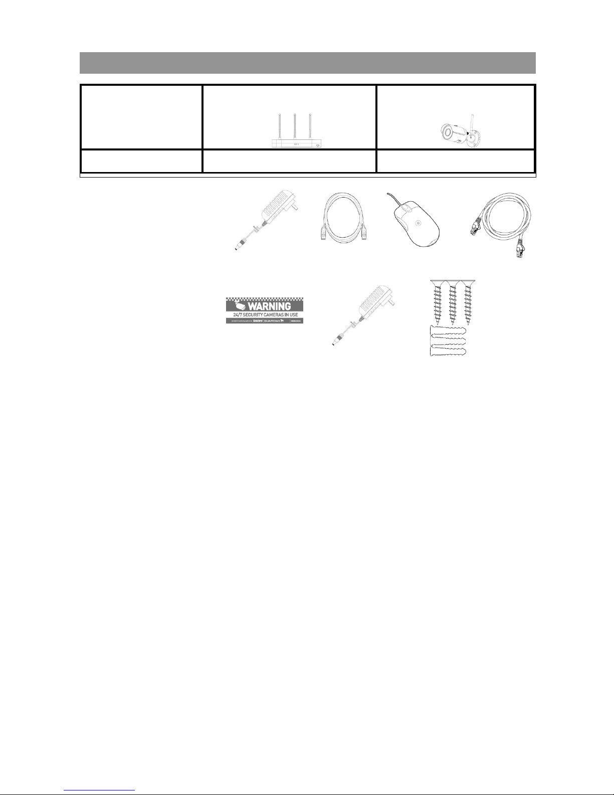
WHAT’S IN THE BOX?
Model GNVR49
Wi-Fi NVR 1TB
App Cam 35
3MP Wireless IP Camera
GNVR 4920W 1 2
Each NVR comes with:
1
2
3
4
5
7
1. NVR Power Supply
2. HDMI Cable
3. Mouse
4. 2m Ethernet Cable
5. Security stickers
Each App Cam 35
comes with:
6. Power Adapter
7. Mounting Screw Kit
6
12
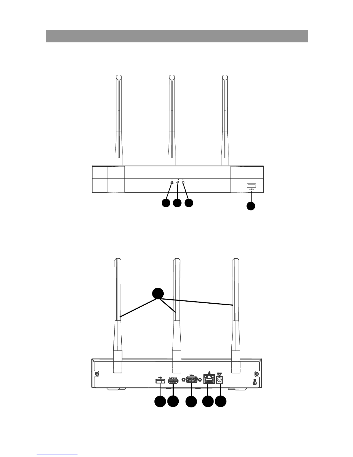
GETTING TO KNOW YOUR NVR
NVR (Front)
NVR (Rear)
21 3
4
5
6
7
8 9
10

13
Indicators & Connectors
No. Label Function
1 Network LED
indicator
The blue light is on when the network connection
is abnormal.
2 Power LED
indicator
The blue light is on when the power connection is
good.
3 HDD LED indica-
tor
The blue light is on when the HDD (Hard Disk
Drive) is malfunctioning.
4 USB2.0 port Connect to a mouse / USB storage device to back
up les or upgrade rmware.
5
6 HDMI video
output port
Connect to a monitor/TV that has HDMI input to
view HD video.
7 VGA video out-
put port
Connect to a monitor that has VGA input to view
video.
8 Network port Connect to the internet with Ethernet cable.
9 Power input port Connect 12V DC adapter to power up the unit.
10 Wi-Fi Antenna Supports 2.4GHz & 5Ghz dual band Wi-Fi.
14
PLACING THE NVR
Please take into consideration the following when placing the NVR.
Ideally, choose a location that is central and has easy access to power sockets.
• Choose a secure location to avoid tampering, however, avoid enclosed
areas as that might lead to overheating of the unit.
• Ensure that the ventilation holes at the side of the NVR are not blocked to
avoid unit from overheating.
INSTALLATION
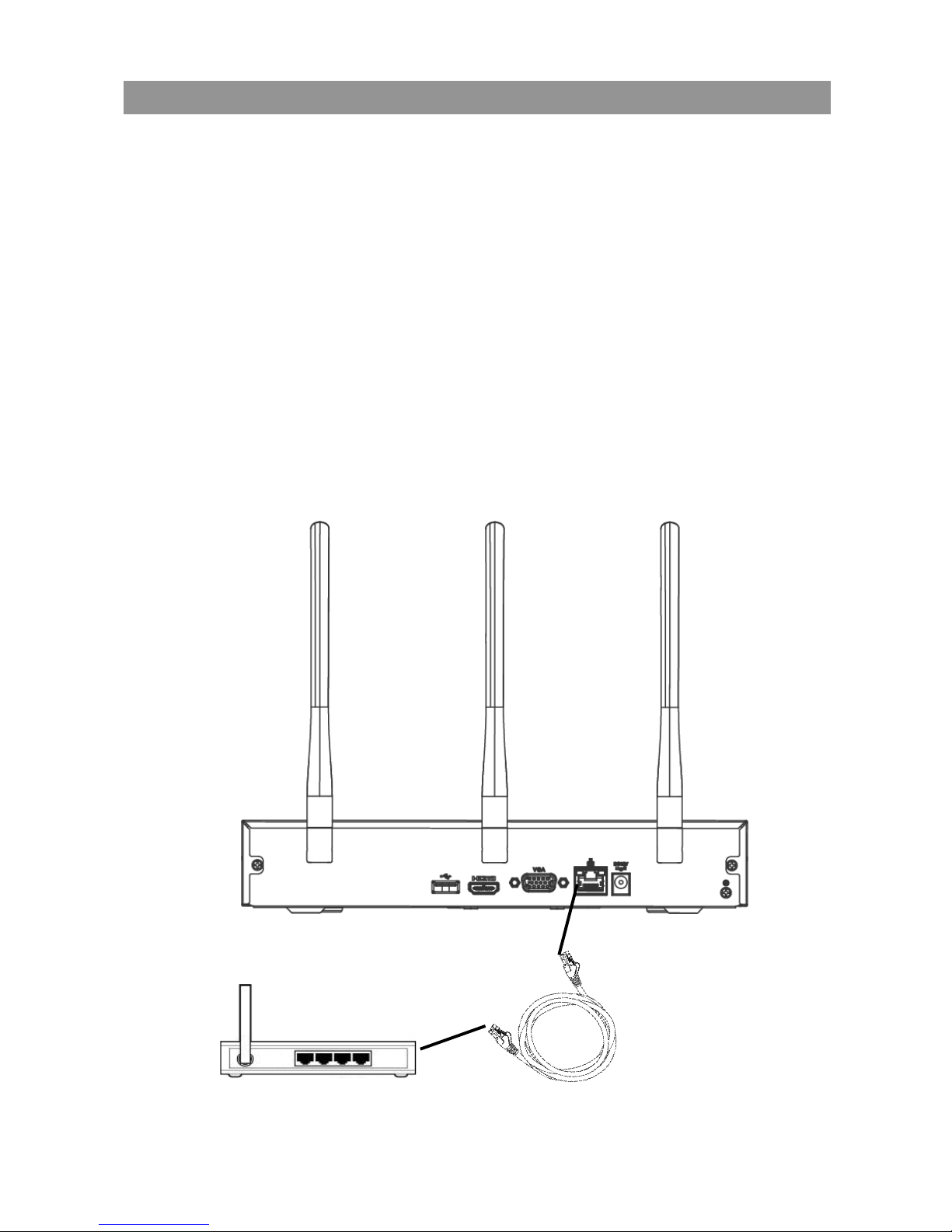
NETWORK CONNECTION
1. Connect the supplied Ethernet cable to the network port on the NVR unit.
2. Connect the other end of Ethernet cable to a router (not included). This will
allows the NVR connected to the internet.
Ethernet Cable
Router (not included)
15
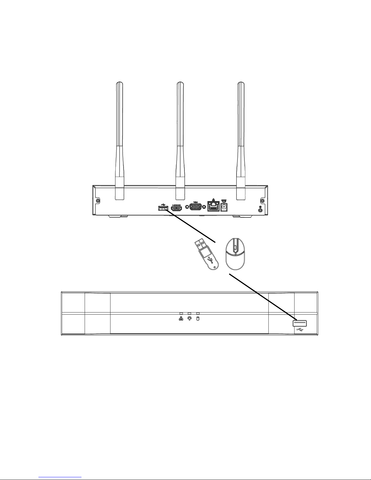
USB CONNECTION
1. Connect one of the USB ports on the NVR unit with the supplied mouse.
2. You can connect the other USB port with USB storage device (not included)
to back up les or to perform rmware upgrades.
or
Mouse
USB Storage Device
(not inlcuded)
16
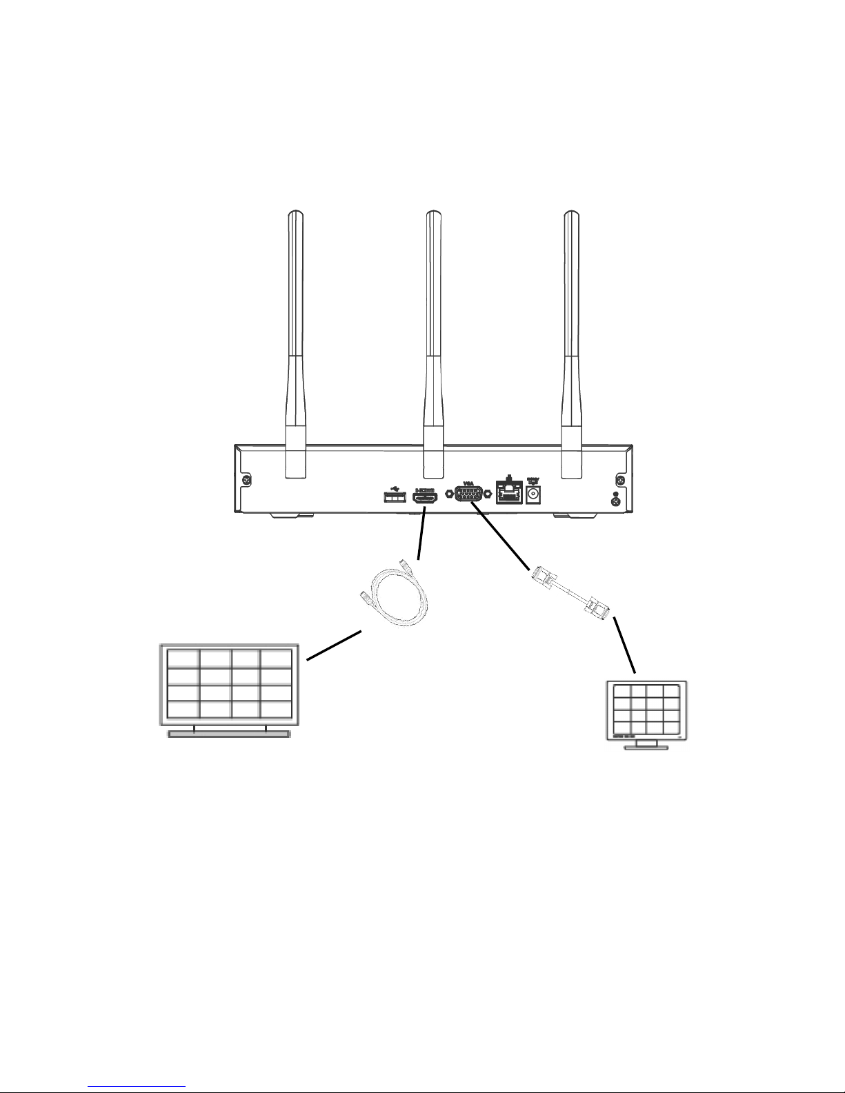
HDMI AND VGA CONNECTIONS
1. Connect the HDMI port on the NVR unit to a HDMI supported monitor or TV
with the supplied HDMI cable.
2. If your TV or monitor only has VGA input port please connect it with a VGA
cable (not included) to the VGA video output port on the NVR.
VGA monitor
(Not included)
HDMI suppo
rted
monito
r
(not included)
VGA Cable
(not included)
HDMI cable
17
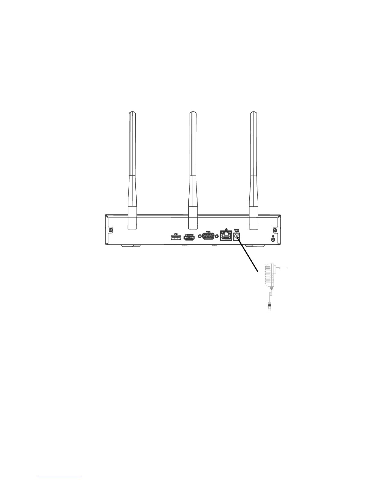
POWER CONNECTION
1. Connect the power input port on the NVR with supplied NVR 12V DC power
adapter.
2. Connect the power adapter to power outlet.
3. Ensure your connections are secured correctly, then switch on the power
outlet to supply power.
To Power
Socket

18
CAMERA CONNECTION
1. Connect the power input port on the camera with supplied App Cam 3x
DC power adapter.
2. Connect the power adapter to power outlet.
3. Ensure your connections are secured correctly, then switch on the power
outlet to supply power.
4. The wireless NVR will auto search nearby wired and wireless(<3m) IP
camera from Uniden.
5. The wireless NVR will add the camera into the system automatically.
6. If you did change the password for the camera before, you will need to
reset the camera. Please press and hold the reset button for 10 seconds
or till the power LED turn off only release it.
7. The wireless NVR will then automatically add the camera into the system.
8. If you have more than 4 IP cameras (wired and wireless) in your network
and couldn’t add the camera that you want, you will need to manual
delete the camera and then only add the camera in the system camera
registration page.
9. For security reason, please modify the camera password in the system
after the camera is added. Do not attempt the modify the camera
password before the system register the password. If you do so, please
perform reset on the camera.
19
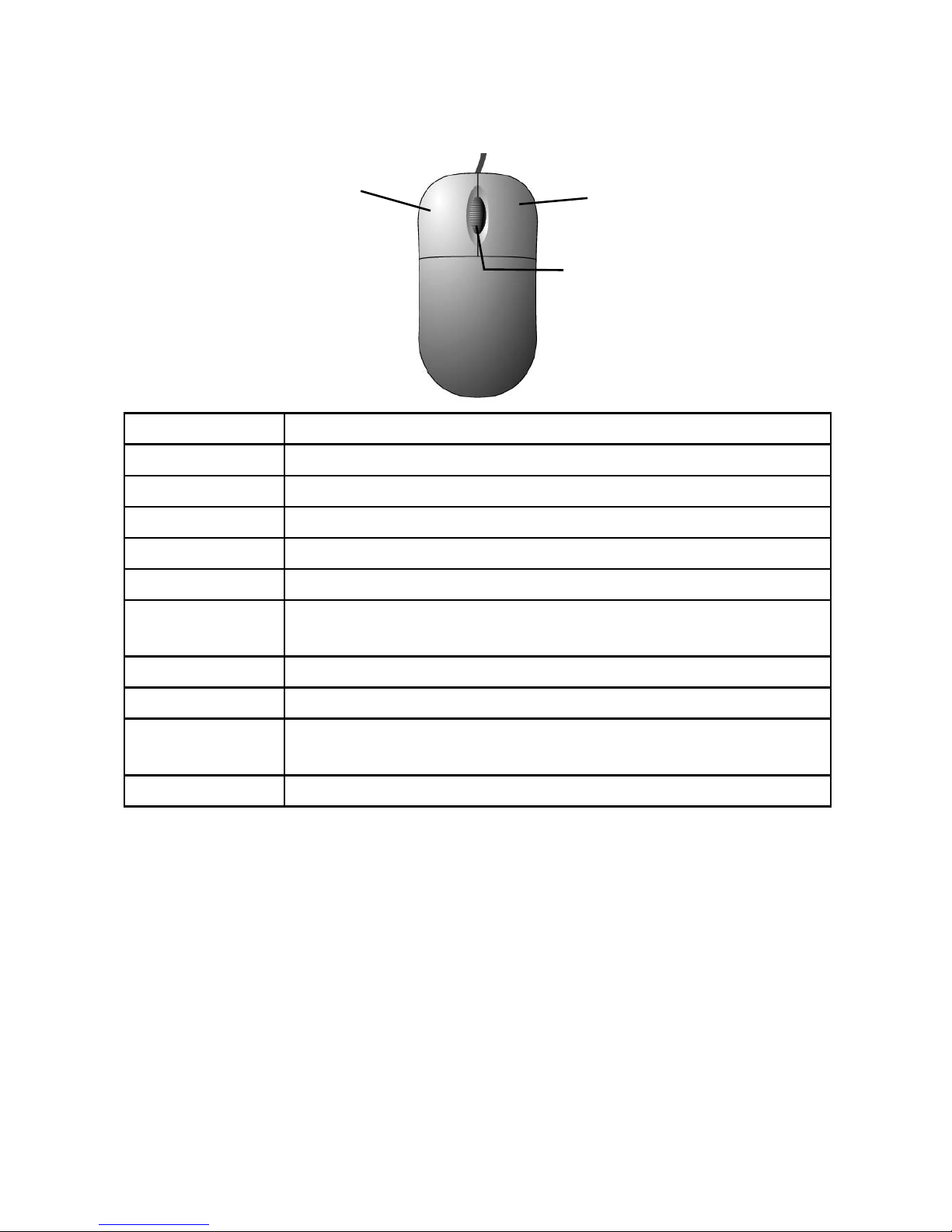
MOUSE CONTROL
The mouse is the primary control device for the system.
Left-button Click once to select an option.
Click once to open navigation bar.
Click once in live view mode go to main menu.
Click once to open menu option.
Double-click an individual channel to view it on full-screen.
Double-click again to return to split-screen display.
Click and drag to select privacy mask zone and motion
detection zone.
Right-button Click once in live view mode go to shortcut menu.
Click once to exit current menu.
Middle-button Click once in numeral input box to increase or decrease
numeral value
Scroll wheel to zoom in/out.
Left-button
Right-button
Middle-button
20
SETUP
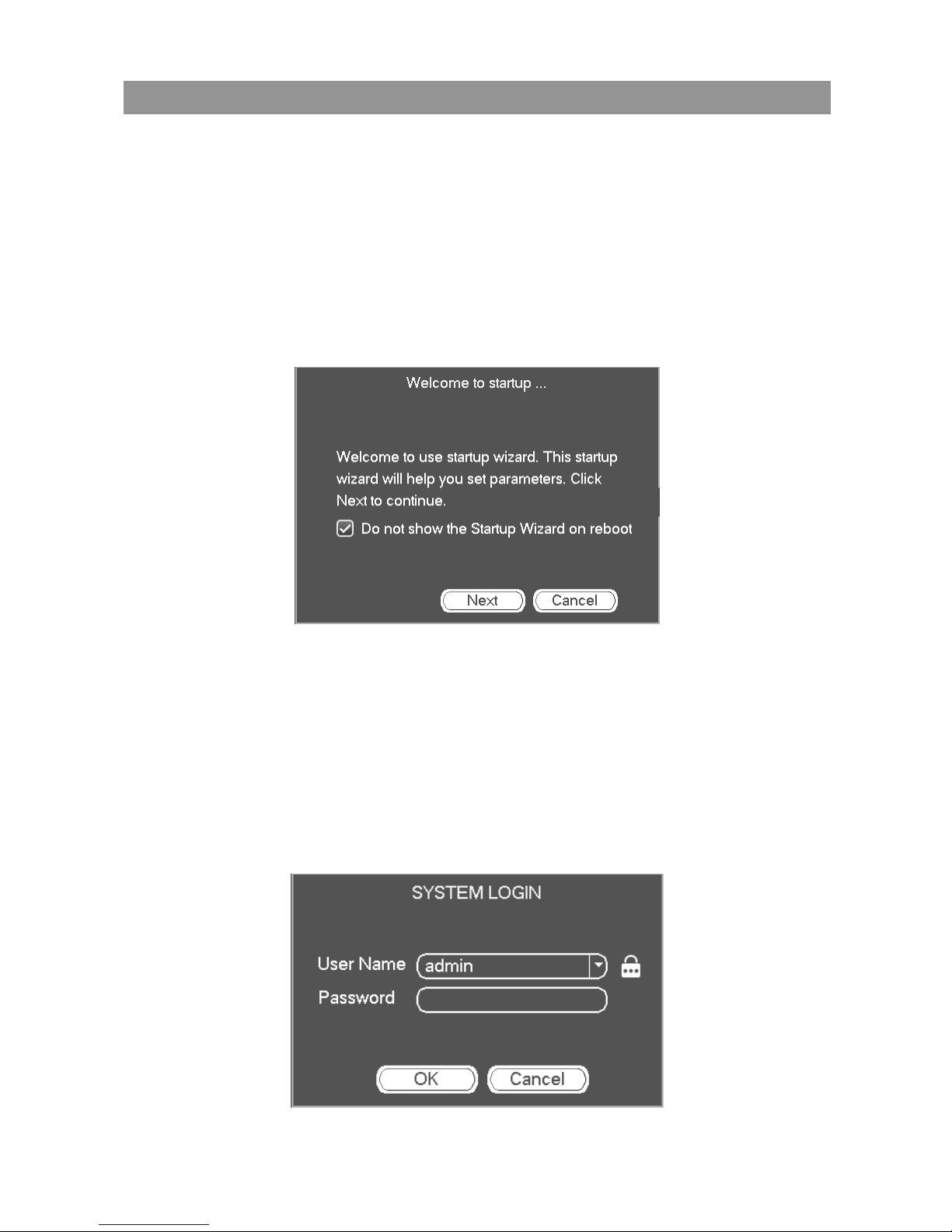
WELCOME TO STARTUP WIZARD
After the NVR unit and cameras are powered up, Startup Wizard will
automatically show up upon first start up. This wizard will guide you to set up
Date & Time and P2P function.
Tick the box if you do want the startup wizard to shows on next boot up.
Click cancel to exit startup wizard; this window will show up on next boot up.
Clicking either cancel or next button will prompt SYSTEM LOGIN screen.
SYSTEM LOGIN
By default, the User Name is admin with no password. You can refer to online
Owner’s Manual to change or add more user name or modify the password
for security reason in system setting.
Important! Do not enter the wrong password more than 5 times or the
account will lock. If this happens, you can try again in 30 minutes!
Click OK button to continue to Date & Time setting page.
21
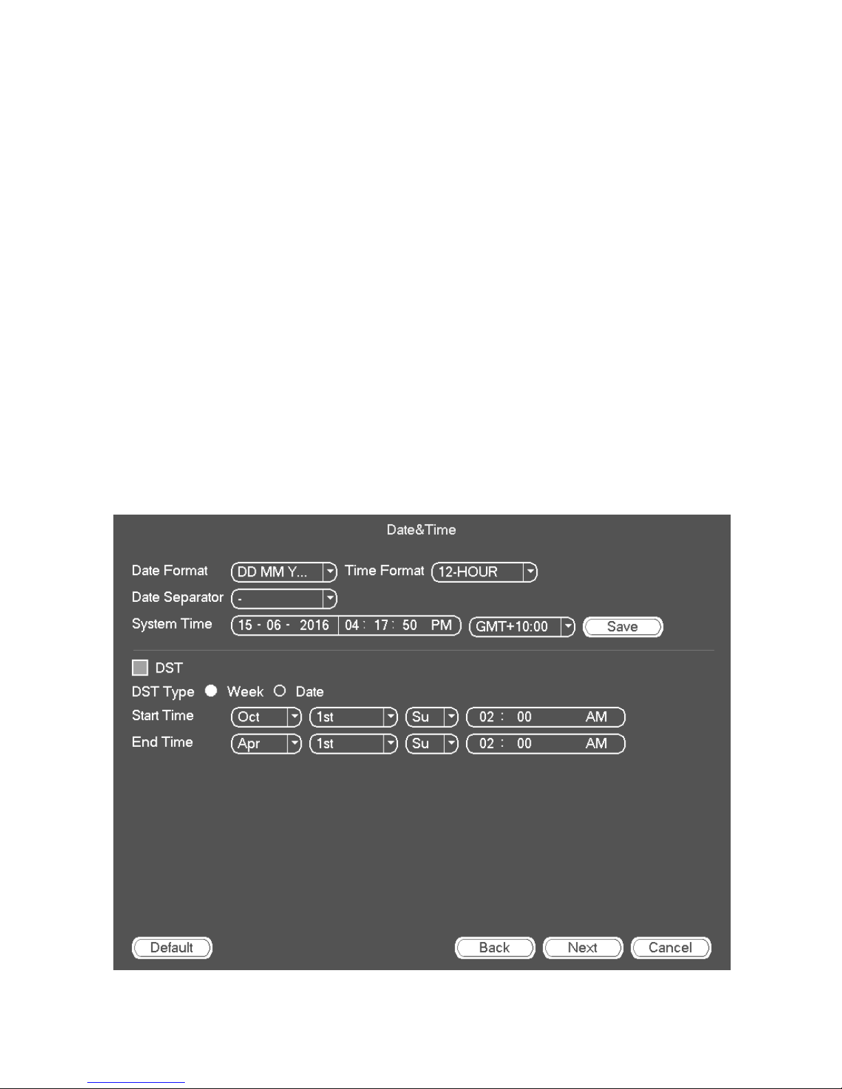
DATE & TIME
• DATE FORMAT: CHOOSE FROM THREE AVAILABLE DISPLAY, DD-MM-YYYY,
YYYYY-MM-DD OR MM-DD-YYYYY.
x Date Separator: Choose from three options to separate date, dot, dash or
slash.
x Time Format: Choose from 12-HOUR or 24-HOUR time format.
x System Time: Set your current date, time and the correct GMT time zone
Untick the DST box if Daylight Savings does not apply to you.
Tick DST box to allow the unit to adjust its time automatically for Daylight
Savings in your time zone.
x DST: You can set the DST Start Time and End Time to function either via
selecting ‘week’ or by manually inputting the date.
x IMPORTANT! Do not skip this step! You must set the date and time for
recorded video files to be correctly tagged. If they are not tagged correctly,
the Search Files functions will not work properly.
22
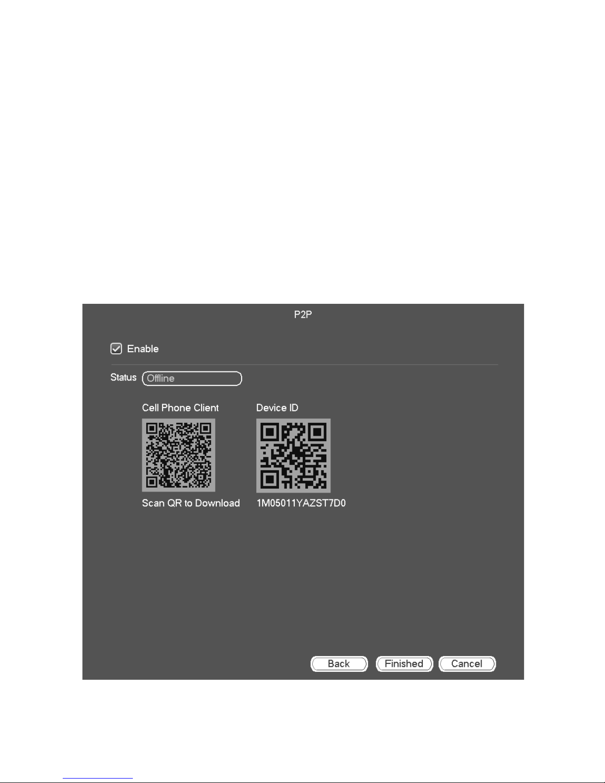
P2P/EASY4IP
P2P is peer-to-peer function that requires internet. If you do not wish to use
the remote viewing feature please untick the Enable box. Please click the
Finished button to complete the Startup Wizard.
If you wish to use remote viewing feature, please tick the Enable box to enable
P2P function if you want to use remote viewing feature.
If the status shows online, the network is connected to the internet.
If the status shows offline, the network is not connected to the internet. Please
ensure your network connections are connected correctly.
Use a Smartphone (not included) or Tablet (not included) to scan the QR
code, it will lead you to download the app called ‘Uniden Live Pro’ or ‘Uniden
Live Pro HD’ from App Store for iOS devices or Play Store for Android
devices.
23
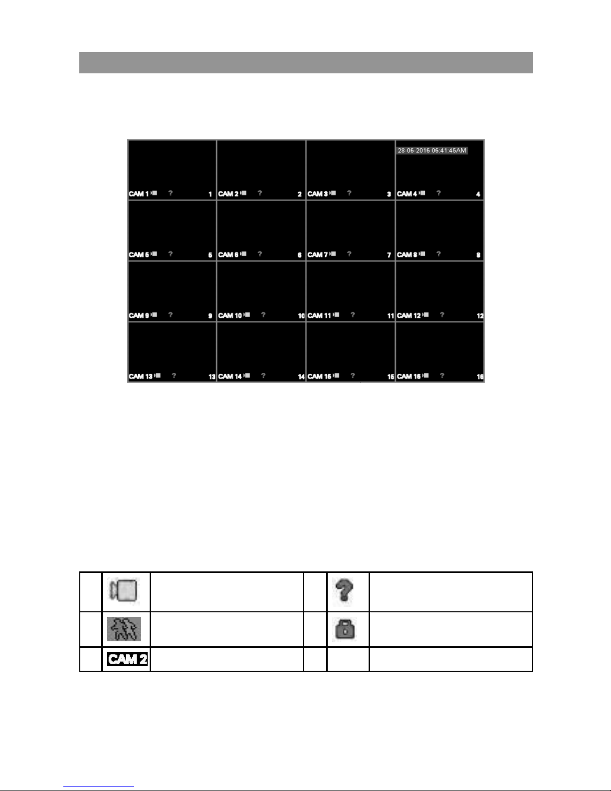
OPERATION
LIVE VIEWING
If all the connections correctly, the system will allow live viewing mode. The
screen will display the date and time at the top right corner of the screen.
Display area:
Double click on a channel to view in full-screen and double click again to
return to split screen.
Right-click to open shortcut menu.
Move the mouse to the top of a channel to view preview control bar.
Click and drag cameras to rearrange channel display but this does not change
the channels of the camera connected.
Icon Labels:
1
Recording Status
3
Video Loss
2 Motion Detection 4
Camera Lock
5 Channel name
24
PREVIEW CONTROL
The preview control has following features.
• Support preview playback.
• In the preview desktop, system can playback previous 5-60 minutes record
of current channel.
• Support drag and play function. You can use your mouse to select any
playback start time.
• Support playback, pause and exit function.
• Support digital zoom function.
• Support real-time backup function.
Digital channel bar (IP Camera connected)
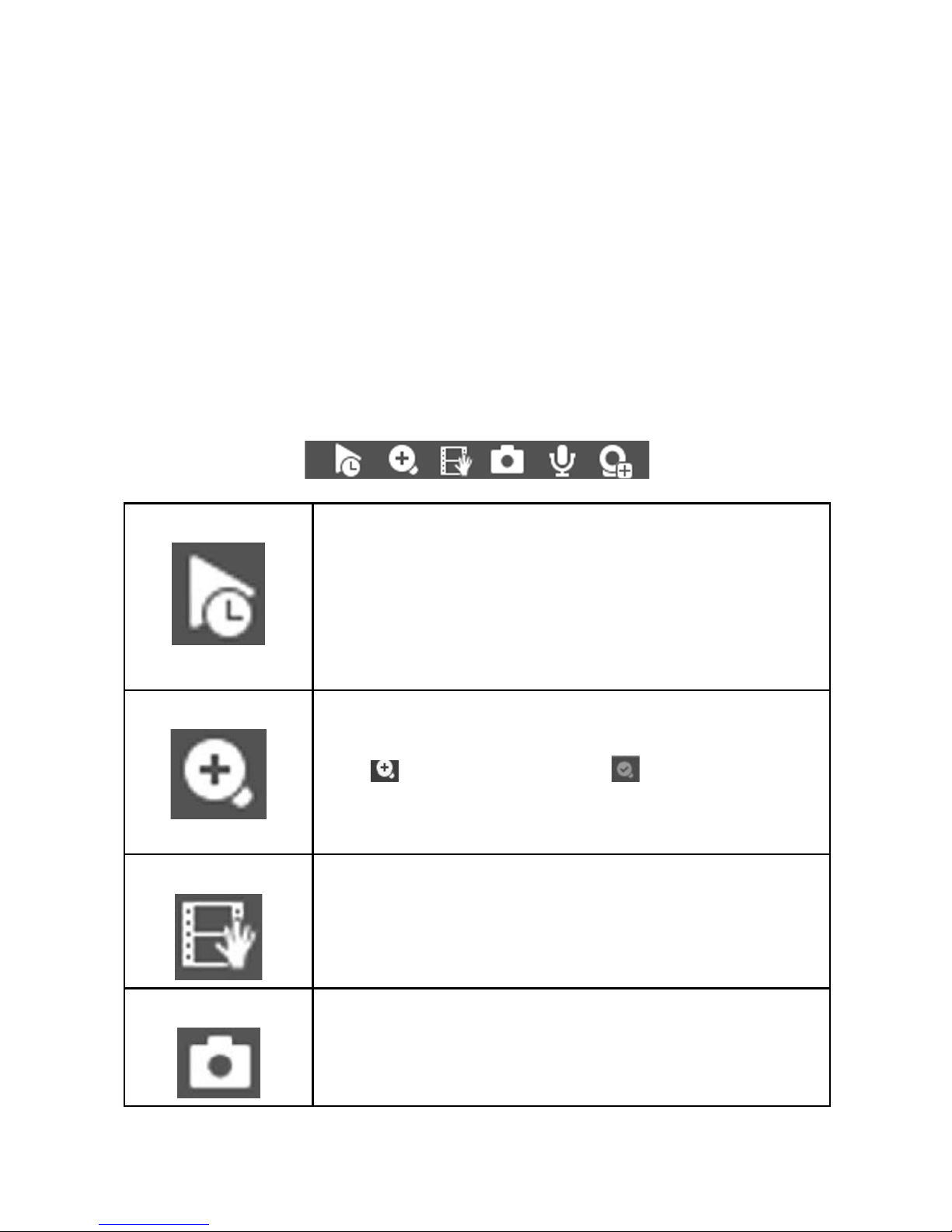
Realtime playback It is to playback the previous 5-60 minutes record of
current channel.
Please go to the Main menu->Setting->System->
General to set real-time playback time.
System may pop up a dialogue box if there is no such
record in current channel.
Digital zoom It is to zoom in specified zone of current channel. It
supports zoom in function of multiple-channel.
Click , then it will change to .
• Click and drag the mouse to select a zone to zoom
in.
Manually record It is to backup the video of current channel to a USB
drive. System can not backup the video of multiplechannel at the same time. Click to begin recording.
Click again to stop recording. You can find the record
file in the USB drive.
Manual snapshot Click to snapshot current channel. The snapshot file
will be saved in the USB drive.
25
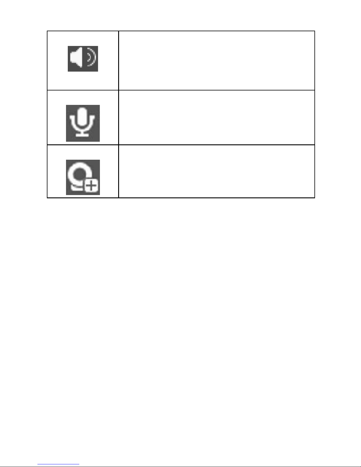
Mute Click to mute. Click again to enable audio function
when preview.
Please note this function is only for one-channel
viewing mode.
Two-way talk If the connected camera supports bidirectional talk
function, you can use this function. Click to start
bidirectional talk function. Click again to cancel
bidirectional talk. You need a microphone (not
included) for this use this function
Remote device Click to go to the remote device interface to add/delete
remote device or view its corresponding information
26
SHORTCUT MENU
Click right button of the mouse during live view mode to view shortcut menu.
Window Switch
System supports 1/4/8/9/16 window (The options depend on your product
channel amount). You can select from the dropdown list.
27
Previous Screen/Next Screen
Click to go to the previous screen/next screen.
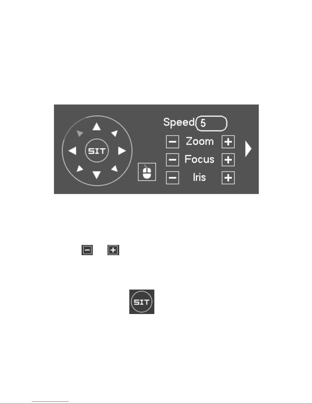
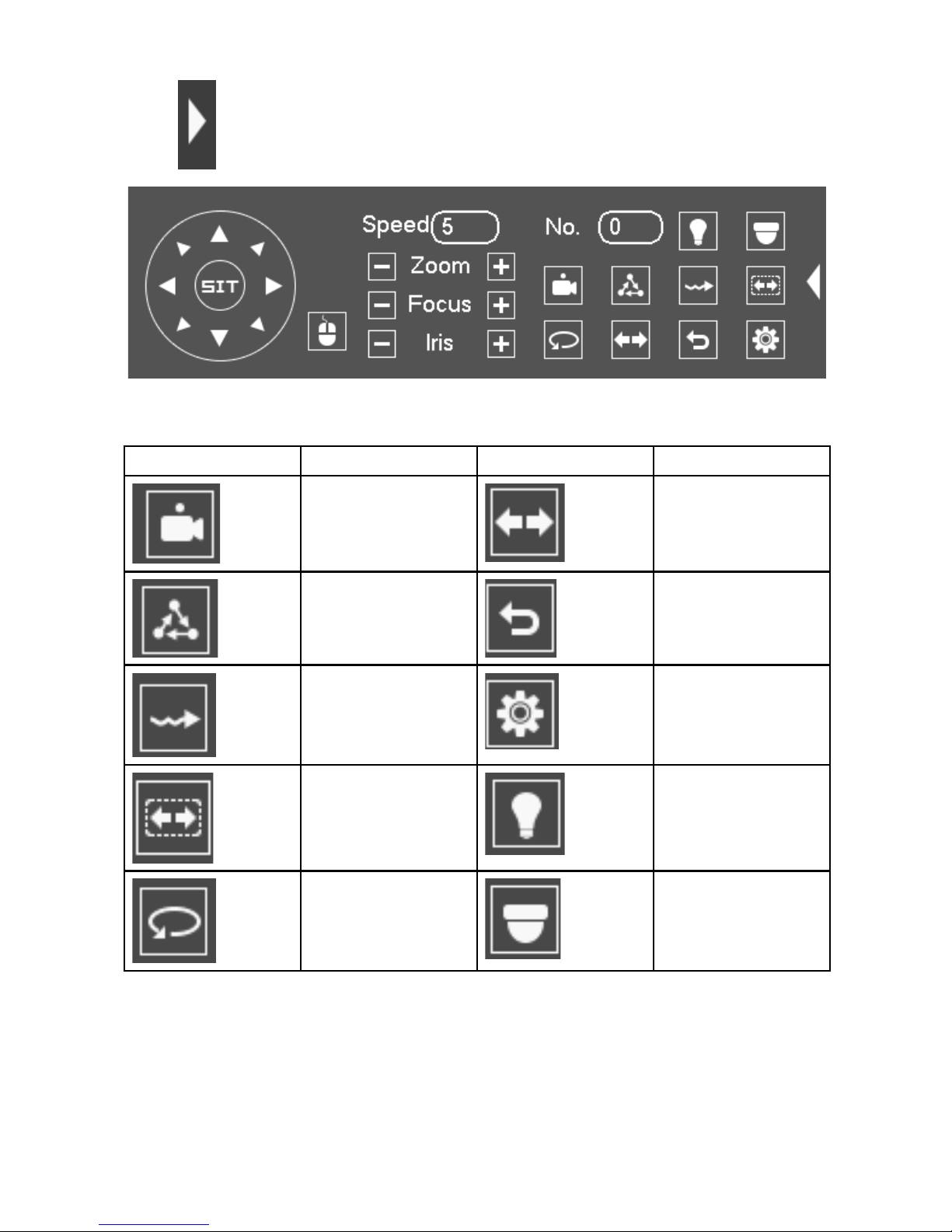
PTZ Control
This function will only works with a PTZ camera. Some functions may not work
with certain PTZ camera. Please refer to your PTZ camera owner’s manual for
compatibility.
Please note this function is only for one-channel viewing mode.
You can control PTZ direction, speed, zoom, focus, iris, preset, tour, scan,
pattern aux function, light and wiper, rotation and etc.
Speed is to control PTZ movement speed. The value ranges from 1 to 8.The
speed 8 is faster than speed 1. You can use the remote control to click the
small keyboard to set.
You can click and of the zoom, focus and iris to zoom in/out, depth of
field and aperture.
The PTZ rotation supports 8 directions.
In the middle of the eight direction arrows, there is a 3D intelligent positioning
key.
Please make sure your protocol supports this function and you need to use
mouse to control.
Click this key, system goes back to the single screen mode. Drag the mouse
in the screen to adjust section size. The dragged zone supports 4X to 16X
speeds. It can realize PTZ automatically. The smaller zone you dragged, the
higher the speed.
28
Click to open the menu, you can set preset, tour, pattern, scan and
etc.
Functions may vary between supported device. Please look into the
device manufacturer for more details.
Icon Function Icon Function
Preset Flip
Tour Reset
Pattern Setting
Scan AUX
Rotate Go to menu
29
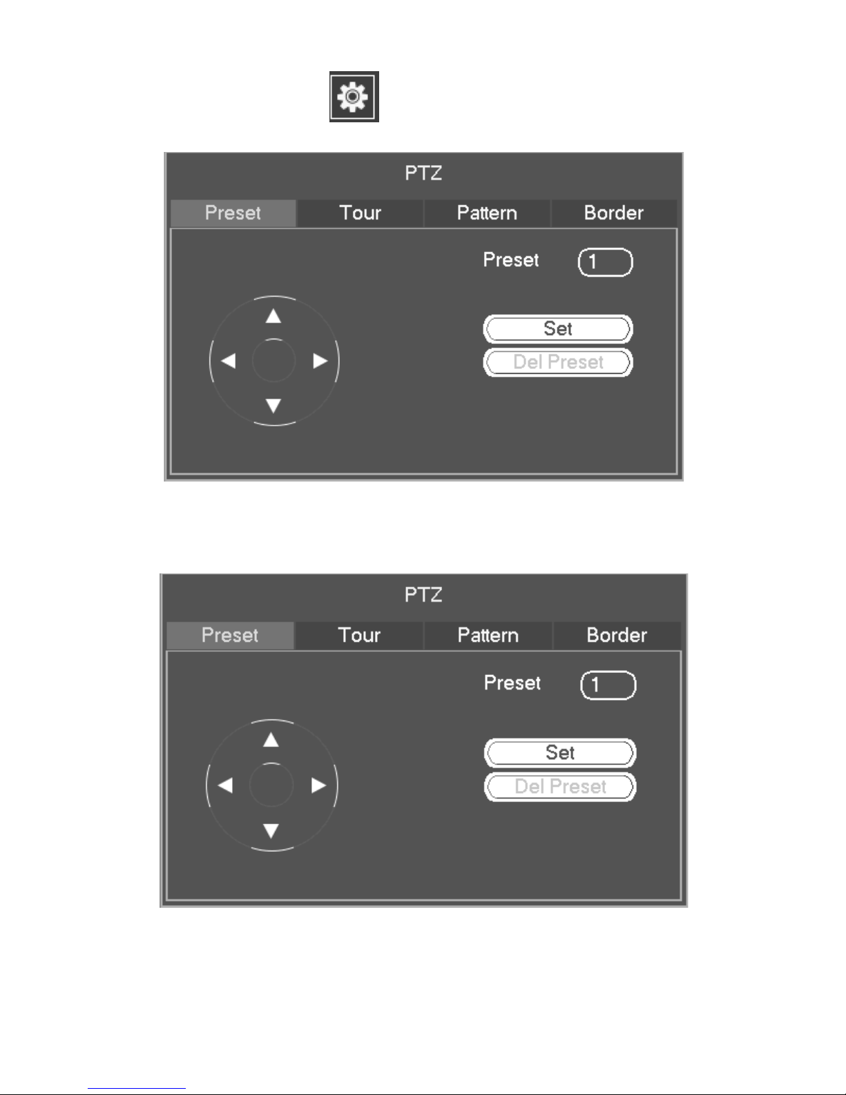
PTZ Function Setup Click , you can go to the following interface to set
preset, tour, pattern, and scan.
Preset Setup
Click preset button and use eight direction arrows to adjust camera to the
proper position.
Click Set button and then input preset number.
Click Set button to save current preset.
30
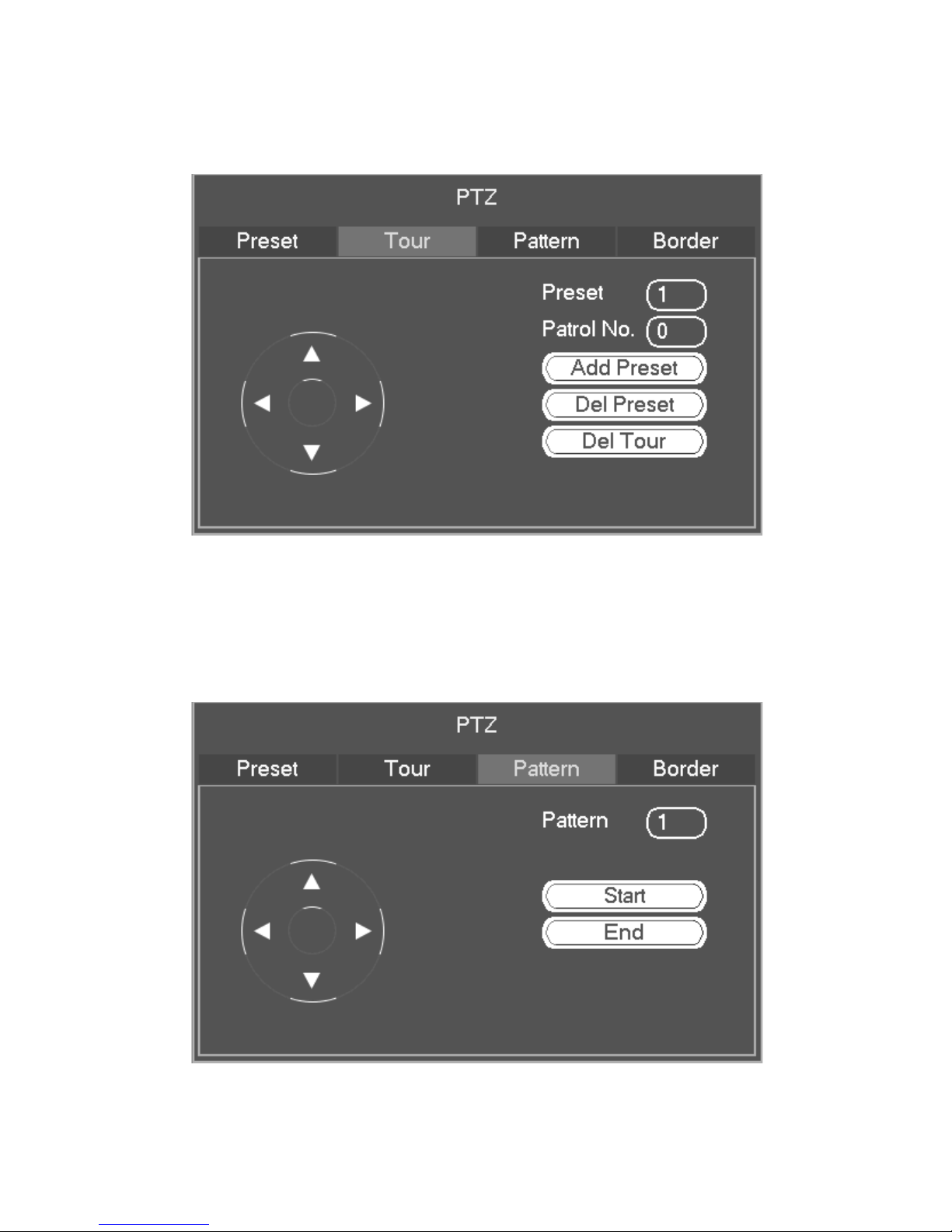
Tour Setup
Input tour value and preset number. Click Add preset button to add current
preset to the tour.
Repeat the above steps if you want to add more presets to the tour. Click Del
preset button to remove it from the tour. Please note not all device support
delete preset function.
Pattern Setup
Click Pattern button and input pattern number.
Click Start button to start direction operation.
Click End button to stop direction operation.
 Loading...