

Uniden GDVR 42 Series, GDVR 82 Series Owner's Manual

GDVR 42/82 Series
Security System
OWNER’S MANUAL
For more exciting new products please visit our website:
Australia: www.uniden.com.au
WARNING
RISK OF ELECTRICAL SHOCK
DO NOT OPEN
WARNING: TO REDUCE THE RISK OF ELECTRIC SHOCK, DO NOT
REMOVE COVER. NO USER SERVICEABLE PARTS INSIDE.
REFER SERVICING TO QUALIFIED SERVICE PERSONNEL.
The exclamation point within an equilateral triangle is intended to alert the
user to the presence of important operating and maintenance (servicing)
instructions in the literature accompanying the appliance.
The lightning flash with arrowhead symbol, within an equilateral triangle, is
intended to alert the user to the presence of uninsulated “dangerous voltage”
within the product’s enclosure that may be of sufficient magnitude to constitute
a risk of electric shock.
WARNING: TO PREVENT FIRE OR SHOCK HAZARD
DO NOT EXPOSE THIS UNIT TO RAIN OR
MOISTURE.
In addition to the careful attention devoted to quality standards in the
manufacturing process of your product, safety is a major factor in the design of
every instrument. However, safety is your responsibility too. This section lists
important information that will help to ensure your enjoyment and proper use
of the product and accessory equipment. Please read them carefully before
operating and using your product.
IMPORTANT SAFEGUARDS

GENERAL PRECAUTIONS
1. All warnings and instructions in this manual should be followed.
2. Remove the plug from the outlet before cleaning. Do not use liquid
aerosol detergents. Use a water-dampened cloth for cleaning.
3. Do not use this product in humid or wet places.
4. Keep enough space around the product for ventilation. Slots and
openings in the storage cabinet should not be blocked.
5. It is highly recommended to connect the product to a surge protector to
protect from damage caused by electrical surges. It is also recommended
to connect the product to an uninterruptible power supply (UPS), which
has an internal battery that will keep the product running in the event of a
power outage.

1. Read and Follow Instructions - All the safety and operating instructions
should be read before the product is set up and used. Follow all operating
instructions.
2. Retain Instructions - These safety and operating instructions should be
retained for future reference.
3. Heed Warnings - Comply with all warnings on the product and in the
operating instructions.
4. Power Sources - This product should be operated only from the type of
power source indicated on the marking label. If you are not sure of the
type of power supplied to your location, consult your video dealer or local
power company. For products intended to operate from battery power or
other sources, refer to the operating instructions.
5. Overloading - Do not overload wall outlets or extension cords as this
can result in the risk of fire or electric shock. Overloaded AC outlets,
extension cords, frayed power cords, damaged or cracked wire insulation,
and broken plugs are dangerous. They may result in a shock or fire
hazard. Periodically examine the cord, and if its appearance indicates
damage or deteriorated insulation, have it replaced by your service
technician.
6. Power-Cord Protection - Power supply cords should be routed so that
they are not likely to be walked on or pinched by items placed upon or
against them. Pay particular attention to cords at plugs, convenience
receptacles, and the point where they exit from the product.
7. Surge Protectors - It is highly recommended that the product be
connected to a surge protector. Doing so will protect the product from
damage caused by power surges.
8. Uninterruptible Power Supplies (UPS) - As this product is designed
for continuous, 24/7 operation, it is recommended that you connect the
product to an uninterruptible power supply. An uninterruptible power
supply has an internal battery that will keep the product running in the
event of a power outage.
9. Ventilation - Slots and openings in the case are provided for ventilation
to ensure reliable operation of the product and to protect it from
overheating. These openings must not be blocked or covered. The
openings should never be blocked by placing the product on a bed, sofa,
rug, or other similar surface. This product should never be placed near
or over a radiator or heat register. This product should not be placed in a
INSTRUCTIONS

built-in installation such as a bookcase or rack unless proper ventilation is
provided and the product manufacturer’s instructions have been followed.
10. Water and Moisture - Do not use this product near water - for example,
near a bath tub, wash bowl, kitchen sink or laundry tub, in a wet
basement, near a swimming pool, etc.
11. Heat - The product should be situated away from heat sources such as
radiators, heat registers, stoves, or other products (including amplifiers)
that produce heat.
12. Accessories - Do not place this product on an unstable cart, stand,
tripod, or table. The product may fall, causing serious damage to the
product. Use this product only with a cart, stand, tripod, bracket, or
table recommended by the manufacturer or sold with the product. Any
mounting of the product should follow the manufacturer’s instructions and
use a mounting accessory recommended by the manufacturer.
13. Camera Extension Cables - Check the rating of your extension
cable(s) to verify compliance with your local authority regulations prior to
installation.
14. Mounting - The cameras provided with this system should be mounted
only as instructed in this guide or the instructions that came with your
cameras, using the provided mounting brackets.
15. Camera Installation - Cameras are not intended for submersion in
water. Not all cameras can be installed outdoors. Check your camera
environmental rating to confirm if they can be installed outdoors. When
installing cameras outdoors, installation in a sheltered area is required.
SERVICE
1. Servicing - Do not attempt to service this product yourself, as opening or
removing covers may expose you to dangerous voltage or other hazards.
Refer all servicing to qualified service personnel.
2. Conditions Requiring Service - Unplug this product from the wall outlet
and refer servicing to qualified service personnel under the following
conditions:
• When the power supply cord or plug is damaged.
• If liquid has been spilled or objects have fallen into the product.
• If the product has been exposed to rain or water.
• If the product has been dropped or the cabinet has been
damaged.

6
• If the product does not operate normally by following the operating
instructions. Adjust only those controls that are covered by the
operating instructions. Improper adjustment of other controls
may result in damage and will often require extensive work by a
qualified technician to restore the product to its nor mal operation.
• When the product exhibits a distinct change in performance. This
indicates a need for service.
3. Replacement Parts - When replacement parts are required, have the
service technician verify that the replacements used have the same
safety characteristics as the original parts. Use of replacements specified
by the product manufacturer can prevent fire, electric shock, or other
hazards.
4. Safety Check - Upon completion of any service or repairs to this product,
ask the service technician to perform safety checks recommended by the
manufacturer to determine that the product is in safe operating condition.
USE
1. Cleaning - Unplug the product from the wall outlet before cleaning.
Do not use liq uid cleaners or aerosol cleaners. Use a damp cloth for
cleaning.
2. Product and Cart Combination - When product is installed on a cart,
product and cart combination should be moved with care. Quick stops,
excessive force, and uneven surfaces may cause the product and cart
combination to overturn.
3. Object and Liquid Entry - Never push objects of any kind into this
product through openings as they may touch dangerous voltage points
or “short-out” parts that could result in a fire or electric shock. Never spill
liquid of any kind on the product.
4. Lightning - For added protection of this product during a lightning storm,
or when it is left unattended and unused for long periods of time, unplug it
from the wall outlet and disconnect the antenna or cable system. This will
prevent damage to the product due to lightning and power line surges.

7
INTRODUCTION ...............................................................................................9
WHAT’S IN THE BOX? ..................................................................................10
GETTING TO KNOW YOUR DVR ................................................................. 11
GETTING TO KNOW YOUR CAMERAS .......................................................12
INSTALLATION ..............................................................................................13
SETUP.............................................................................................................14
SYSTEM LOGIN .................................................................................14
REQUIRED SETTINGS ......................................................................14
DEFAULT OPERATION SETTINGS ...................................................15
HOW DO I - .........................................................................................16
SEARCH FOR FILES ..........................................................................16
SET UP ALARMS AND ALARM NOTIFICATION? .............................16
PLAY BACK RECORDED FILES ........................................................16
FIND AND VIEW SHAPSHOTS ..........................................................16
MASK MOTION SENSITIVE AREAS ..................................................16
SET UP EMAIL NOTIFICATION AND ALERT ....................................16
CONFIGURE ALARMS .......................................................................16
CREATE A RECORDING SCHEDULE ...............................................17
TRANSFER RECORDED FILES ........................................................17
ADD OR CHANGE A PASSWORD .....................................................17
GUARDIANLIVE APP ....................................................................................18
USING THE APP .............................................................................................18
BASIC OPERATION .......................................................................................23
SYSTEM LOGIN .................................................................................23
LIVE VIEW .........................................................................................23
SYSTEM MENU ..................................................................................25
MAIN MENU OVERVIEW ...............................................................................27
SETUP ICON ...................................................................................... ...28
BASIC
SCREEN ..................................................................................28
LIVE SCREEN .....................................................................................32
RECORD SCREEN .............................................................................34
SCHEDULE SCREEN .........................................................................39
ALARM SCREEN ................................................................................40
NETWORK SCREEN ..........................................................................46
USERS ICON ......................................................................................49
PTZ ICON ............................................................................................52
ADVANCED ICON ..............................................................................54
CONTENTS

8
SEARCH ICON ...................................................................................... 58
TIME SEARCH TAB ............................................................................59
EVENT SEARCH TAB ........................................................................60
FILE MANAGEMENT TAB ..................................................................61
IMAGE TAB .........................................................................................62
BACKUP ICON ...................................................................................... 63
INFORMATION ICON ............................................................................ 64
SYSTEM SCREEN ..............................................................................64
EVENT LIST SCREEN ........................................................................65
LOG LIST SCREEN ............................................................................65
NETWORK SCREEN ..........................................................................66
ONLINE USERS LIST SCREEN .........................................................66
EXIT SCREEN ....................................................................................66
DISK MANAGEMENT ICON .................................................................. 67
LOG OFF ICON ..................................................................................... 68
SHUT DOWN ICON ............................................................................... 68
REMOTE ACCESS .........................................................................................69
FIRMWARE UPDATES ...................................................................................70
TROUBLESHOOTING ....................................................................................71
SPECIFICATIONS ..........................................................................................75
WARRANTY ...................................................................................................78

9
OVERVIEW
The Guardian DVR D1 (GDVR D1) system operates with an embedded LINUX
operating system for increased stability. It also uses standard H. 264 video
compression and G. 711 audio compression technology which provide high
quality, detailed playback and analysis. TCP/IP network technology provides
the GDVR D1 system with strong network data transmission.
The GDVR D1 works as a stand-alone surveillance system or as part of
a larger surveillance network. Its professional network video surveillance
software provides strong network communication and telecommunication
ability.
ABOUT THIS MANUAL
This OM provides operating procedures for the GDVR D1 system. The GDVR
D1 models operate identically. There are only 2 differences between the
models: the number of channels and the number of cameras.
• GDVR 4222: 2 outdoor cameras, 2 indoor cameras, 4 channels.
• GDVR 4220: 2 outdoor cameras, 4 channels.
• GDVR 4240: 4 outdoor cameras, 4 channels.
• GDVR 8242: 4 outdoor cameras, 2 indoor cameras, 8 channels.
All procedures apply to all models unless specifically noted. Some screen
illustrations show entries for all 8 channels and some show for only 4
channels.
INTRODUCTION
10
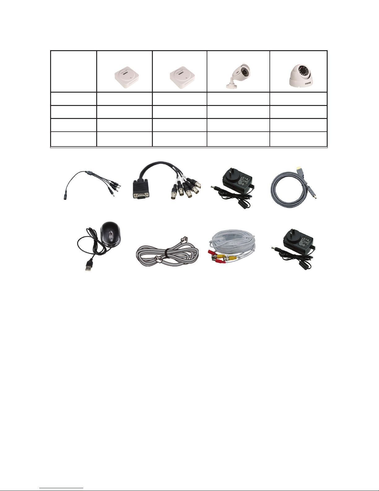
What’s in the Box
Model 4-Ch DVR 8-Ch DVR Outdoor Camera Indoor Camera
GDVR 4220 1 2
GDVR 4222 1 2 2
GDVR 4240 1 4
GDVR 8242 1 4 2
Each DVR comes with:
7. Video Power Cable
8. AC Adaptor
9. Mounting Screws (not shown here)
1
2
3
4
5
6
7 8
1. Power Splitter Cable
2. Video Splitter Cable
3. AC Adaptor
4. HDMI Cable
5. Mouse
6. Ethernet Cable
With 500GB HDD
With 500GB HDD
Each Camera comes with:
11
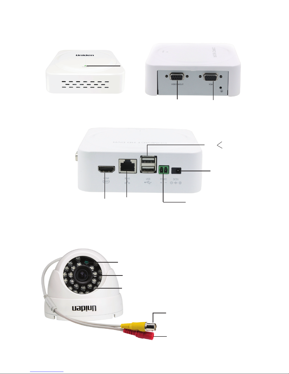
Getting to Know Your DVR
Getting to Know Your Cameras
Indoor Camera
VIDEO IN/OUT
(Connect Video
Splitter Cable)
VGA
HDMI
(Connect
HDMI Cable)
RJ45
(Connect
Ethernet Cable)
USB
RS485
DC5V
(Connects to
external display)
(Connect to
the Mouse)
(Connects
to external
hard disk)
(Connect AC
Adaptor)
(If using PTZ
camera)
Power
LED
Infra-red LEDs
Camera Lens
Light Sensor
BNC Video Connector
(Yellow)
Power Connector
(Red)
12
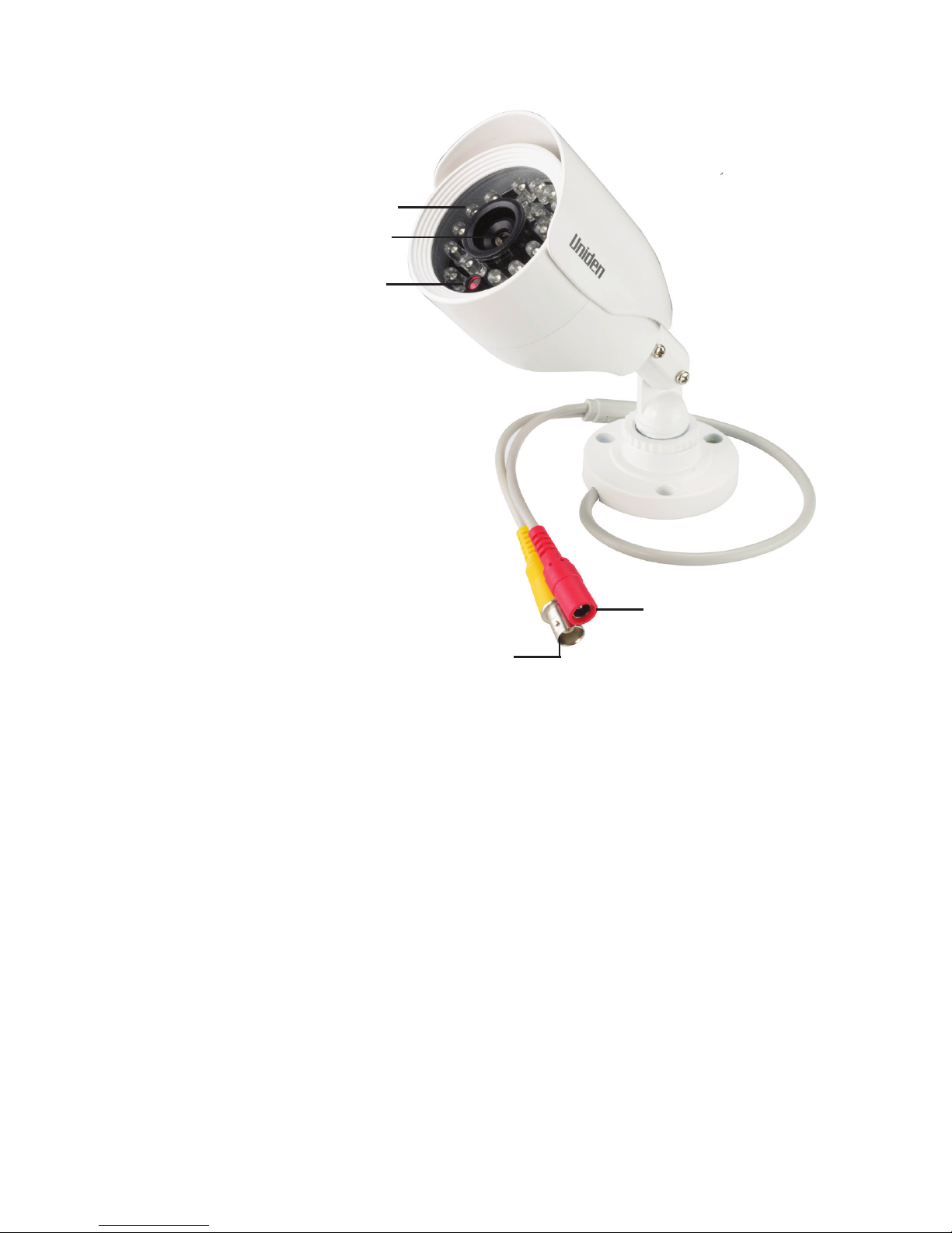
Outdoor Camera
Ideally, indoor cameras should not be easily visible whereas outdoor cameras
should be visible, making it a deterrent for intruders.
Light Sensor
Camera Lens
Infra-red LEDs
BNC Video Connector
(Yellow)
Power Connector
(Red)
13
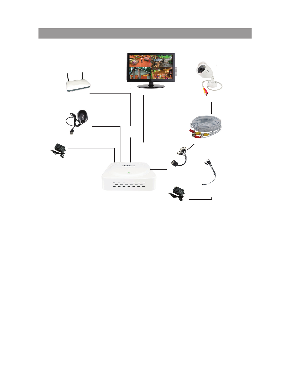
1. Connect the camera to the connectors on the Video Power cable.
2. Connect the yellow BNC connector of the Video Power cable to the Video
Splitter cable. Then, plug the Video Splitter cable into the VIDEO/IN/OUT
port on the DVR.
3. Connect the red power connector of the Video Power cable to the Power
Splitter cable.
4. Connect the HDMI cable (supplied) to the HDMI port on the DVR and to the
external display device (TV/PC) or use the VGA cable (not supplied) for the
VGA port.
5. Connect the Mouse to one of the USB ports on the DVR.
6. Connect the Ethernet cable to the RJ45 port on the DVR and to your
modem/router (for remote viewing).
7. Connect the Power Splitter cable to the camera’s AC adaptor, which
connects to a power outlet.
8. Plug the DVR’s AC Adaptor jack into the DC5V port (on the DVR) and the
other end to a power outlet.
INSTALLATION
Follow the steps below to connect the DVR and the camera(s).
DVR
Mouse
Camera
Video Power Cable
Power Splitter
Cable
Video Splitter
Cable
HDMI
Cable
Ethernet
Cable
AC Adaptor
(To Power Outlet)
External Display
Modem/Router
AC Adaptor
(To Power Outlet)
14
SETUP
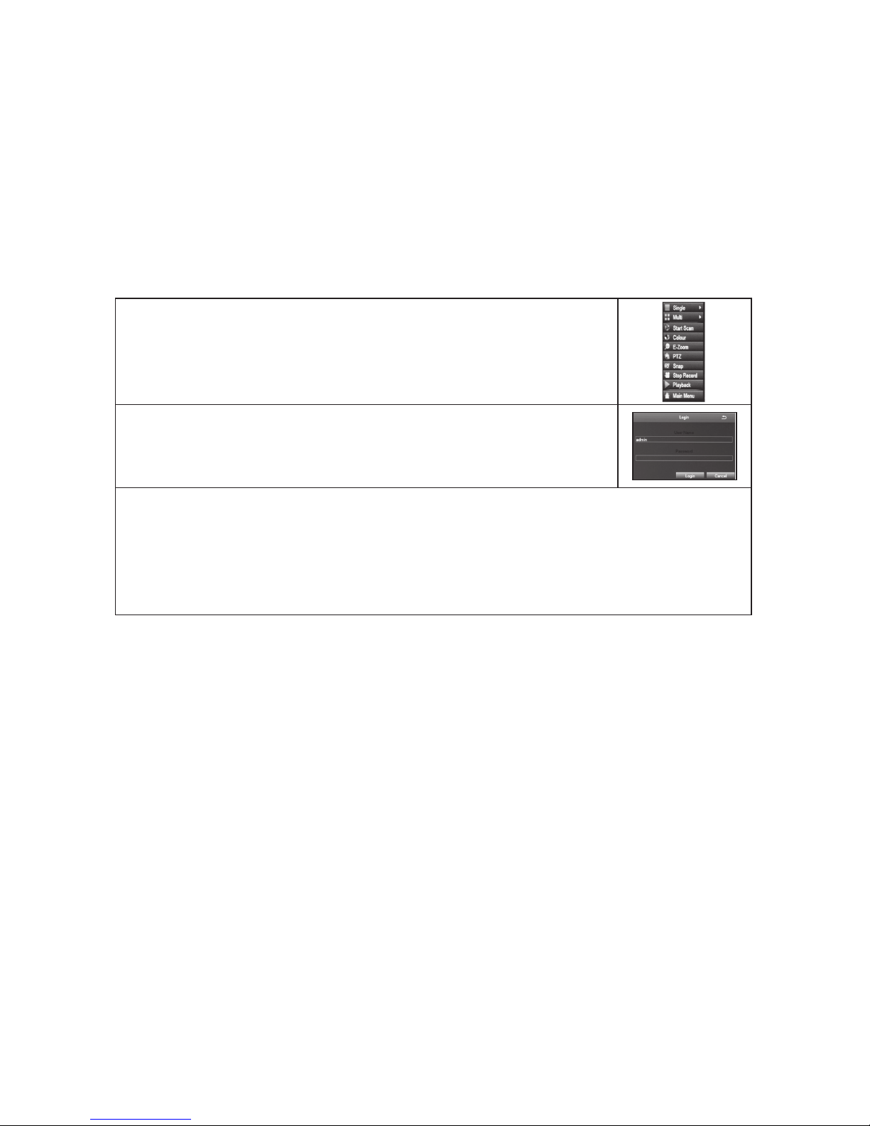
Live video displays when you power up the system. However, until you log in,
you can only view live video; you cannot access any other system operations.
(For the initial set up, a series of Wizard screens pop up. Change the default
parameters, if necessary, if not, click Next, till you reach the screen that
displays Finish. Click Finish.)
System Login
1. Right-click on the screen. The system menu displays.
2. Select any option. The
Login
screen displays.
3. The default values are
admin
(user name) with no password. Select
Login
. The system displays the active screen for the selection you
made in the previous step. (See page 52 to set up a password.)
It is strongly recommended that you add a password to the admin
account and to all other accounts you may add to the system.
Required Settings
Set the system date and time so recorded files will be correctly timestamped.
Next, create a password for the “admin” user.
Set Date and Time
The correct date and time are critical for the timestamp on recorded files. If the
timestamp is incorrect, searching for a specific recorded file will be difficult.
From
Main Menu/Setup/Basic
, select the
Date & Time
tab. See page 30 for
detailed descriptions of the tab’s fields.
Set Password
Passwords prevent unauthorized access to system configuration screems. The
Admin user originally has no password so you can log into the system for setup.
Uniden strongly recommends that, once you have logged into the system,
you create a password for the Admin user.

15
From
Main Menu/Users/User Management
, select the
Password
field. See
page 52 for a detailed description on how to set up a password.
Default Operation Settings
Uniden’s default settings allow you to begin monitoring your network
immediately. After you have monitored your network for a week or two, you
may find you need to slightly adjust your settings. For example, you may need
to mask areas from motion detection (trees, etc).

16
HOW DO I -
Search for Files
There are three basic methods for searching files – search for files within a
certain timeframe, search a timeframe for triggered files, and search for events
through the Information screen.
The first two methods use the
Search
screen (
Main Menu/Search
).
1. Select
Main Menu/Search
. The
Search
screen displays.
2. Select the
Time Search
tab to find files within a specific time frame or the
Event Search
tab to find motion sensor, sensor-triggered, or all triggered
files.
3. From the Main Menu/
Information/Event
List, set up what time frame and
cameras you want to search and whether you want to search for Motion,
Sensor, or Video Loss (this screen is similar to the
Search
screen above).
Select
Search
tab and records that meet those criteria, display.
Set Up Alarms and Alarm Notication
Main Menu/Setup/Alarm/OtherAlarm
Play Back Recorded Files
• Right-click
Playback
on
System
Menu to view the last 30 minute segment.
• Main Menu/
Setup/Search
(Time Search or Event Search tab)
Find and View Snapshots
Main Menu/Search/Image
Mask Motion Sensitive areas
Main Menu/Setup/Alarm/Motion, Area field
Set Up Email Notication and Alert
Main Menu/Setup/Network, Email tab
Congure Alarms
Main Menu/Setup/Alarms. Select type of alarm (Motion, Video Loss, or Other
Alarm).

17
Create a Recording Schedule
Main Menu/Setup/Schedule. You can set up recording by a specific calendar
schedule.
Transfer Recorded Files from the Hard Drive to a
USB Device
Main Menu/Setup/Advanced/Inport/Export tab.
Add or Change a Password
Main Menu/Setup/Users/User Management, Change Password field.
18
GUARDIANLIVE APP
USING THE APP
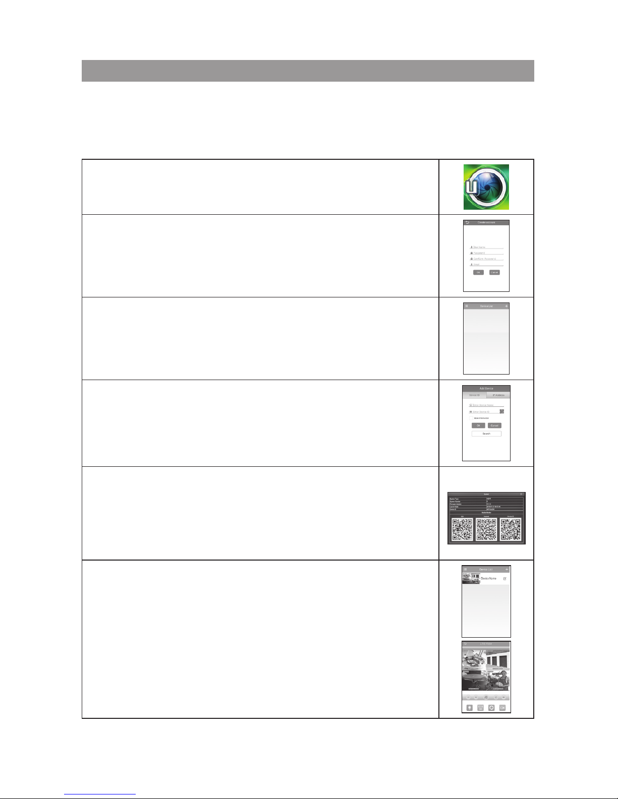
View live and recorded video remotely using an iOS or Android device and
Uniden’s GuardianLive App.
1. From the Apple App Store or Google Play, download
the Uniden GuardianLive app.
2. Open the app. Tap Create Account. The
Create
Account
screen displays.
3. Complete the fields and then select OK. The login
screen appears again. Input your device name and
password again and the Device List screen displays.
4. Select the + icon at the top right corner to add your
DVR system to the app. The
Add Device
screen
displays.
5. Name your DVR system. Select the QR code icon
and scan the QR code label on the DVR receiver or
the applicable Device ID QR code from
Main Menu/
Information/System
screen on the monitor. This will
add the DVR Device ID code to the app. Select OK.
6. The
Device List
displays again, with your system now
listed. Select your system and live video displays on
your device.
19
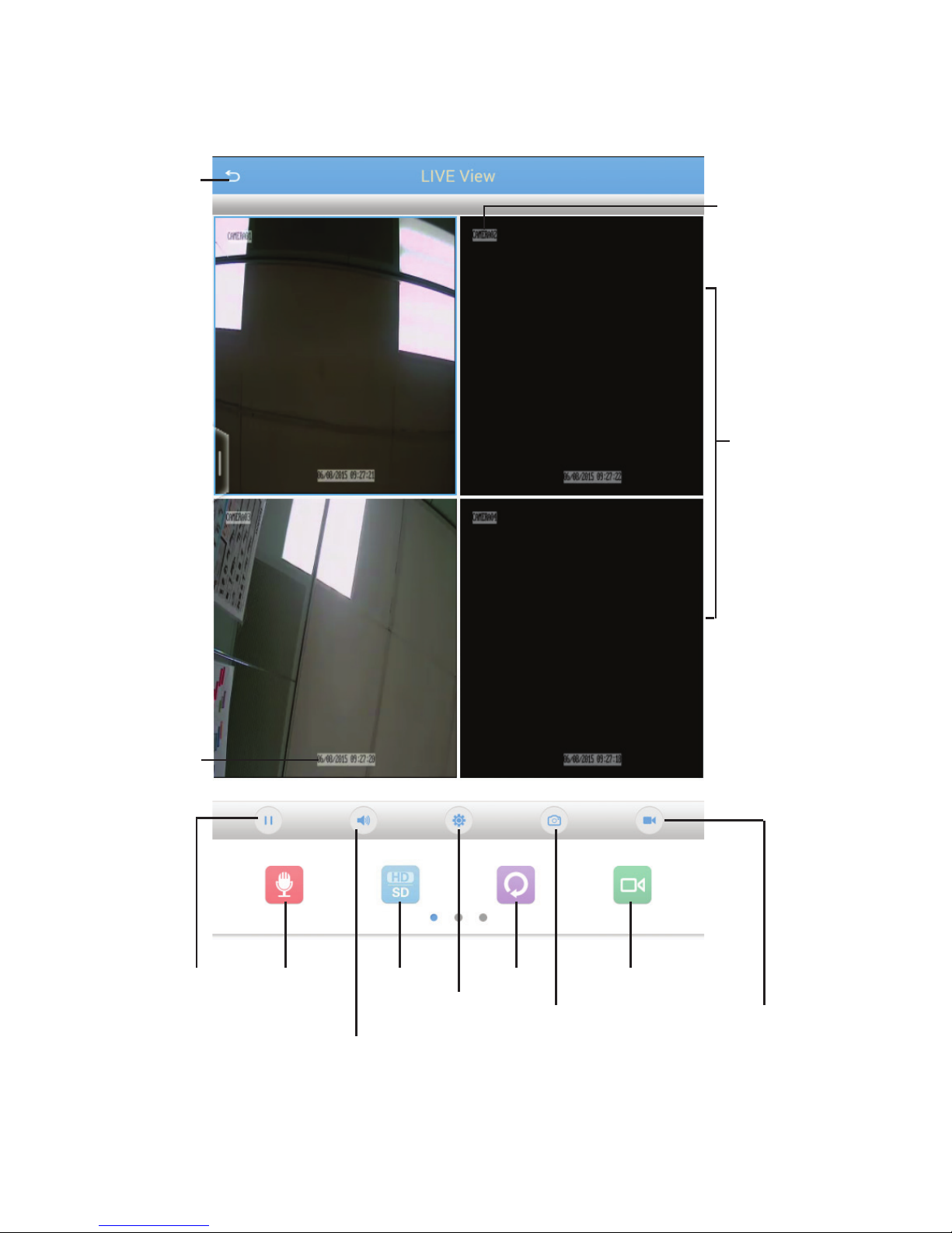
LIVE SCREEN
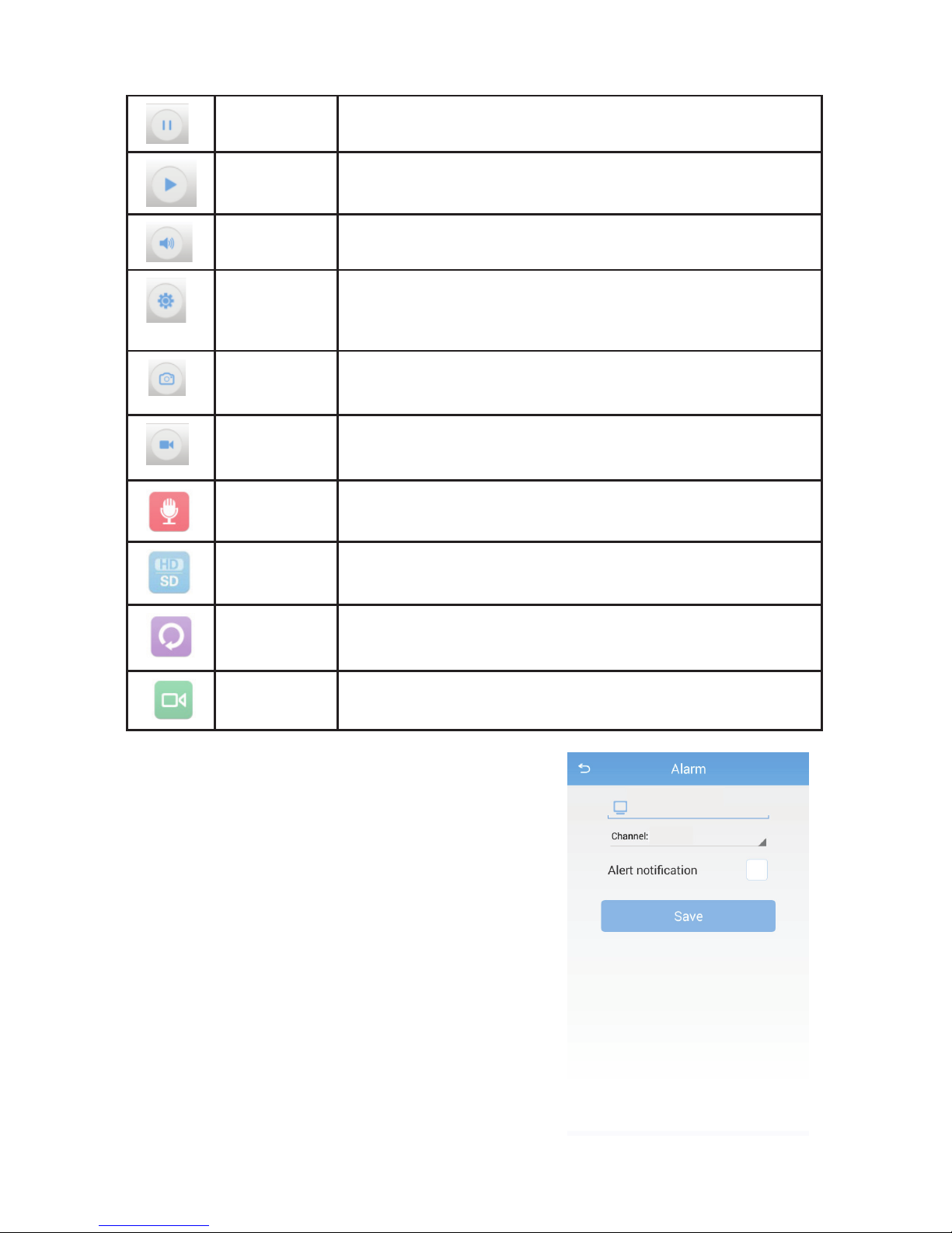
Live Screen is the main screen in the GuardianLive app.
Quad
View
Pause Microphone
Audio
HD/SD
Alarm
Refresh
Snapshot
Remote Playback
Record
Back
Camera
Name
Date
&Time
display
20
Pause Tap on a camera view and tap the Pause icon to
stop live view.
Play Tap on a camera view and tap the Play icon to start
the streaming of live view.
Audio Tap to turn on audio (not available on all models).
Alert Tap to open the Alarm setting screen and save
configuration, so that you can be alerted when
motion is detected.
Snapshot Tap the camera view that you want take a snapshot
of and then tap the snapshot icon.
Recording Tap the camera view that you want to record and
then tap the Record icon.
Mic Tap to record sound.
HD/SD Tap to view either in ‘High Definition’ or ‘Standard
Definition’.
Refresh Tap to refresh live view.
Playback Tap to playback recorded video.
ALERT SCREEN
On the app, in the live view, tap the Alert icon to
get the Alarm screen displayed.
Tap the Alert Notification check box, then
tap save, to get an alert on the app when the
camera detects motion.
Please ensure that the motion dection is turned
on in your system.
21
ABOUT SCREEN
On the Device List screen, tap on the Menu
icon (top left corner) to reveal menu options,
About, Recordings, Snapshots and Logout.
Tap the option, About. It displays the latest
firmware version.
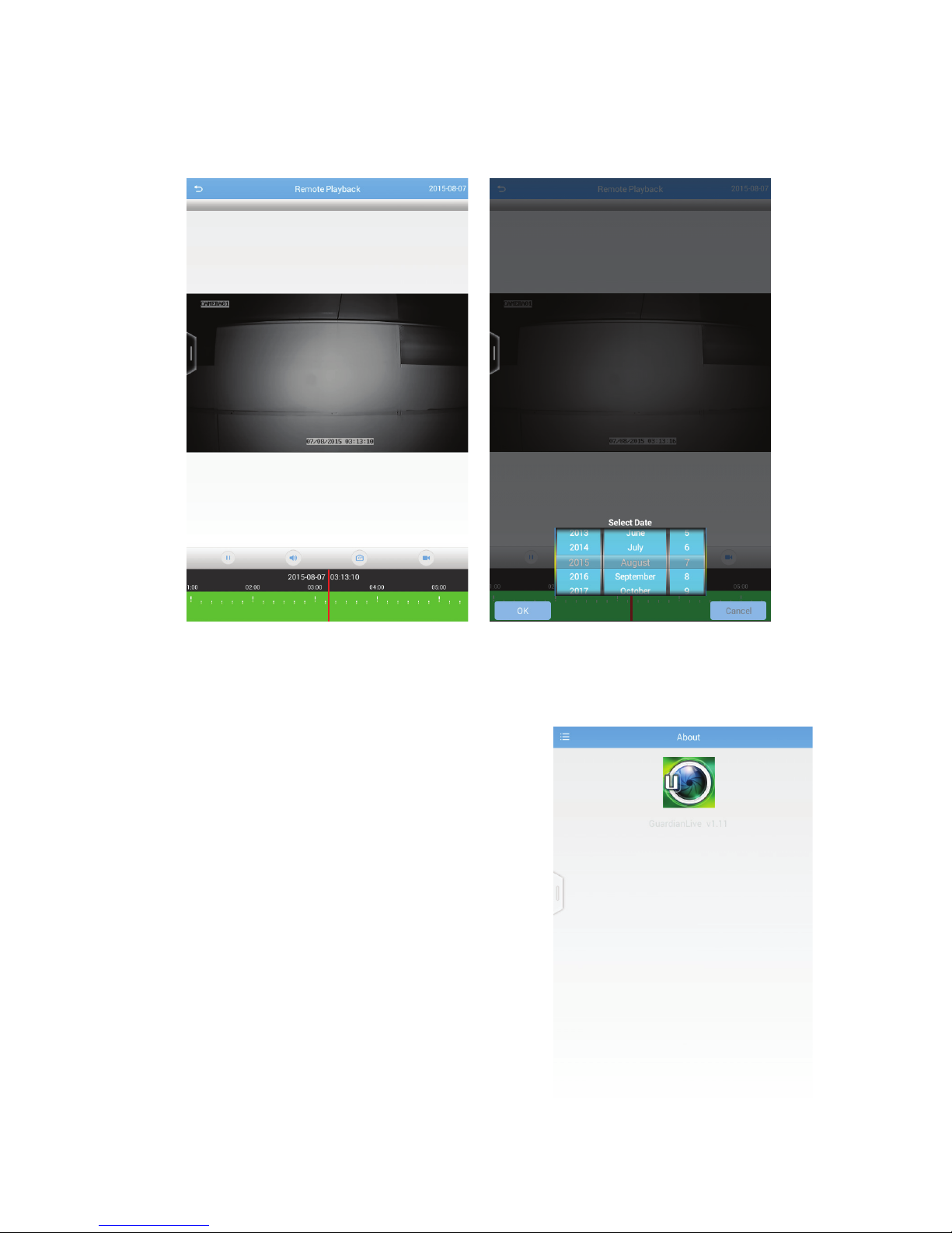
REMOTE PLAYBACK SCREEN
On the app, in the live view, tap the Playback icon to get the Remote Playback
screen displayed.
Tap the date displayed on the top right corner of the screen to get the Select
Date pop-up box. Tap to scroll through the dates and select the dates that you
want to play the recorded video.

22
SNAPSHOT SCREEN
On the Device List screen, tap on the Menu icon (top left corner) to reveal
menu options, About, Recordings, Snapshots and Logout.
Tap the option, Snapshots, to view the images that have been taken using the
app. Please note, these images are NOT stored on the hard disk.
LOGOUT
Tap to logout of the app.
RECORDINGS SCREEN
On the Device List screen, tap on the Menu icon (top left corner) to reveal
menu options, About, Recordings, Snapshots and Logout.
Tap the option, Recordings, to view the recordings that have been initiated on
the app. Please note, these recordings are NOT stored on the hard disk.

23
Live video displays when you power up the system. However, until you log in,
you can only view live video; you cannot access any other system operations.
SYSTEM LOGIN
1. Right-click on the screen. The system menu displays.
2. Select any option. The
Login
screen displays.
3. The default values are
admin
(user name) with no password. Select
Login
. The system displays the active screen for the selection you
made in the previous step. (See page 52 to set up a password.)
It is strongly recommended that you add a password to the admin
account and to all other accounts you may add to the system.
LIVE VIEW
Live view displays video images from all 4/8 cameras. The date, time, and
camera number display in each viewing window. The recording and alarm
status icons display in the lower left-hand corner of each window.
Double-click the left mouse button on a live view image to view that image in
full screen rather than in a 4-part window. Double-click the left-mouse button
again to return to quad view.
BASIC OPERATION
24
IMAGE MEANING
Recording Type - indicated by box color
• Green - Manual or triggered recording
• Yellow - Motion detection recording
• Blue - Timing recording
• Red - Alarm recording
Motion Detected. This icon displays when the camera
for that view detects motion.
Network Disconnected
DD/MM/YYYY
HH:MM:SS
Date and Time Stamp for recorded files
 Loading...