

Page 1
GC45 AND GC45W ACCESSORY
CAMERA USER’S MANUAL
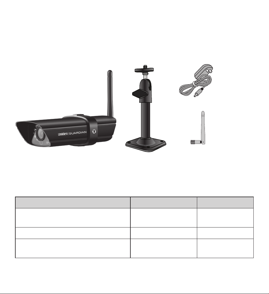
WHAT’S IN THE BOX
AC adapter
GC45 or GC45W video camera
Camera stand
If any items are missing or damaged, contact our Customer Care Line
immediately. Never use damaged products!
Need Help? Get answers 24/7 at our website: www.uniden.com.
Camera
antenna
Four Wall
Anchors and
screws
(Not Shown)
If You... Contact Uniden’s... Phone Number
have a question or problem
need a replacement part or accessory Parts Department* 800-554-3988
need special help due to a disability
* During regular business hours, Central Standard Time. Visit our website for detailed
business hours.
Customer Care
Line*
Accessibility Help
Line
817-858-2900 or
800-658-8068
800-874-9314
(voice or TTY)
Page 2

Important Safety Instructions!
This manual contains important information about this product’s operation. If
you are installing this product for others, you must leave this manual or a copy
with the end user.
When using your equipment, always follow basic safety precautions to reduce the risk of
re, electric shock and injury to persons, including the following:
• This equipment is NOT waterproof.
• DO NOT immerse any part of the product in water. Do not use this product near water,
e.g., near a bath tub, wash bowl, kitchen sink or laundry tub, in a wet basement or near
a swimming pool.
• To avoid any risk of electric shock from lightning, avoid handling any electronic
devices (except battery powered ones) during an electrical storm.
• Use only the power cord and/or batteries indicated in this manual. Never dispose of
any batteries in a re: they may explode. Check with local codes for possible special
disposal instructions.
• Never tug or pull on any power cord: be sure to leave some slack in the cord when
placing your equipment, and always use the plug to unplug cord from the wall outlet.
• Never leave power cords where they can become crushed, cut, or frayed; when
running power cords, avoid letting them rub against any sharp edges or lie across any
high trac areas where people might trip over them.
• Do not use the device if the adapter cords or plugs have been damaged, the unit has
been exposed to liquids, or the unit has been dropped or is damaged.
Warnings to Parents and Other Users
Failure to follow these warnings and the assembly instructions could result in serious
injury or death. This product is not designed or intended for use as a medical monitor,
nor should this product be used as a substitution for medial or parental supervision.
Always be sure that both the transmitter and receiver are working properly and are
within range of each other.
• STRANGULATION HAZARD. Keep the adapter cords out of the reach of children.
Page 3

• WARNING: KEEP OUT OF THE REACH OF CHILDREN. This product is not a toy and is not
intended for use by any children under the age of 13. If you are between the ages of
13 and 18, review these terms, conditions and safety warnings with your parents or
guardian to make sure that you and your parent or guardian understand these terms,
conditions, and safety warnings.
• Allow for proper ventilation when units are in use. Do not cover the camera or receiver
with any object such as a blanket. Do not place it in a drawer or in any location which
would mue the sound or interfere with the normal ow of air.
SAVE THESE INSTRUCTIONS!
For best results:
To avoid damage to your equipment, follow these simple precautions:
• Do not drop, puncture or disassemble any part of the equipment. There are no user-
serviceable parts inside.
• Do not expose the equipment to high temperatures; avoid leaving the equipment in
direct sunlight for more than a few minutes. Heat can damage the case or electrical
parts.
• Do not place heavy items on top of the equipment or expose the equipment to heavy
pressure.
• Remove the power adapter during long periods between usages.
• Clean only with a dry cloth.
Failure to follow the instructions in this operating manual will void the warranty.
Uniden assumes no liability for damages to property or injury to persons caused
by improper handling or failure to comply with these safety instructions.
Page 4

CONTENTS
Important Safety
Instructions! .......................2
Warnings to Parents and
Other Users ................... 2
For best results: .................... 3
Getting to know the camera .5
Camera components and
indicators ................................. 5
What the lights mean ............. 5
Mount the Camera Stand ......6
General Guidelines .................. 6
Placement Considerations ... 6
Attach the camera ................... 7
Pairing Cameras .....................9
Some things to know about
pairing cameras ..................... 9
Pair Camera ................................ 9
Troubleshooting camera
Pairing ..................................... 10
Product Specications ........11
Additional Information .......13
Recycling and Disposal
Information ......................13
FCC Compliance Information 13
Part 15 Compliance
Statement .....................13
RF Exposure Information 14
IC Compliance Information .14
Radio Equipment Notice 14
CE Compliance Information 14
One-year Limited Warranty 15
4
Page 5
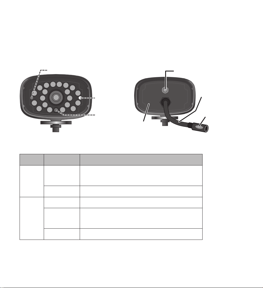
GETTING TO KNOW THE CAMERA
Power status
Antenna
CAMERA COMPONENTS AND INDICATORS
Front view Back view
connector
Link status
Light sensor
WHAT THE LIGHTS MEAN
Light State What it means
Power
status
Link
status
On
(Red)
Off The camera is off.
Flashing The camera is in pairing mode.
On
(Green)
Off The camera is in standby.
The camera is on.
The camera is connected to the receiver.
Power
pigtail
Power/Pair
button
Microphone
5
Page 6

MOUNT THE CAMERA STAND
GENERAL GUIDELINES
The Uniden Guardian GC45 and GC45W cameras are weatherproof and have an
IP66 rating. Water can be sprayed on them and they will still work; however, the
cameras cannot be submerged underwater.
Although the cameras can be exposed directly to the rain, it is recommended
that, if they are used outdoors, they be mounted under some type of cover like
a patio overhang or eave. As rainwater drops start to dry on the camera glass, it
can create spots that will reflect the light from the infrared LEDs used for night
vision, thus causing lower quality video.
Also, as dust, grime, and cobwebs accumulate on the camera glass, they can
reflect light from the infrared LED and might lower video quality. Periodically
clean the lens glass with a soft cloth.
PLACEMENT CONSIDERATIONS
Consider the following when placing cameras:
• The clearest line-of-sight between the camera and monitor is best.
— Walls, especially brick and concrete, shorten the transmission distance.
— Placement next to windows allows better transmission.
• Optimized motion detection range is 6 - 18 feet for the GC45 camera. The
farther away an object is, the less accurate the motion detection.
• Avoid having a direct light source in the view of the camera, including street
lights, ceiling or floor lamps, spotlights in the driveway, etc.
6
Page 7

• Rainfall, pool water ripples/reflections, tree/shrub leaves blowing in the wind
- and the shadows they create - can generate motion detection false alarms.
You can mount the camera with the stand on the bottom (on a wall or tabletop) or on the top (on the ceiling). When you are positioning the camera, you
might want to bring the receiver along; it’s much easier to get the camera into
the right position when you have the display handy.
1. Hold the base of the camera stand where you want to mount it and mark
the location of the screw holes.
2. Use the included screws and anchors to attach the base to the wall or
ceiling.
ATTACH THE CAMERA
Before attaching the camera, tug gently on the stand to make sure it is securely
in place.
1. For each camera, attach the camera bracket to the mounting screw. You
can attach the stand to the top or the bottom of the camera as needed.
Tighten it a few turns, then turn the camera
to face the direction you want.
2. Tighten the camera brace up against the
camera to secure it into place.
3. Unlock the mounting post by turning the
wingnut to the left a few turns.
4. Set the mounting post to the correct angle,
then tighten the wingnut until the post is
locked into place.
5. Attach the antenna to the rear of the camera.
7
Page 8

6. Connect one end of an AC adapter to the camera’s power pigtail and plug
Attach the camera
the other end into a 120 volt AC (standard indoor) power outlet (if
necessary, connect
the extension cord to
the camera’s pigtail
and connect the AC
Tighten the brace against
2
the camera to
secure it
in place.
1
to the mounting
screw and turn it
to the desired
direction.
adapter to the
extension cord).
Be sure the power
plug and the
connector are tightly
twisted together to
avoid water leaking
3
Loosen the
wingnut to
unlock the
mounting
post.
Adjust the post to
4
the correct angle,
then tighten the
wingnut to lock the
post into place.
in.
7. Make sure the
status
light turns
on. If it doesn’t, try
Power
reconnecting the AC
adapter, and make sure the power outlet isn’t controlled by a wall switch.
Antenna
Power/
Pair button
8
Page 9

PAIRING CAMERAS
Your receiver supports a total of four active cameras at a time. When you add
a camera, you have to pair it to the receiver (that is, you have “introduce” the
camera and receiver so they can communicate).
SOME THINGS TO KNOW ABOUT PAIRING CAMERAS
• If a camera is already assigned to the selected channel, the receiver
overwrites that camera link with the new one.
• Only pair one camera at a time! The receiver links to the first camera it
detects. If two or more cameras are in pairing mode, you can’t control which
camera the receiver will detect first.
PAIR CAMERA
1. From the Pairing Camera screen (refer to the G455/G755 Owner’s Manual),
tap the camera image you want to pair. A processing icon displays for a 60
second countdown.
2. During the 60 second countdown, quickly press and release the Pairing
button on that camera’s power cord (refer to the G455/G755 Owner’s
Manual).
3. The system automatically adjusts the Camera On screen accordingly.
If you have any trouble, consult the table on page 10.
Use this Pairing Camera procedure to move a camera from one channel
to a different channel.
9
Page 10

TROUBLESHOOTING CAMERA PAIRING
Consult the following table for camera pairing troubleshooting suggestions:
If... Try...
• making sure the camera is plugged in and the red
LED is on.
the camera’s signal
status icon shows no
bars
the camera’s signal
status icon shows
one or two bars or the
video quality is poor
the camera won’t pair
with the receiver
• making sure that the camera’s antenna is attached
and the receiver’s antenna is extended.
• making sure the camera is paired to the correct
channel
• re-pairing the camera and receiver
Refer to the G455/G755 Owner’s Manual, “General
Guidelines” for tips on improving video quality.
• making sure the camera is plugged in and the red
LED is on.
• pressing and releasing the pairing button quickly. Do
not press and hold the pairing button.
10
Page 11

PRODUCT SPECIFICATIONS
The following specifications apply to both the GC45 and GC45W cameras.
Radio Frequency Transceiver
RF Frequency 2.4 GHz
Modulation GFSK
Spread spectrum Frequency Hopping
Anti Interference Clean Channel Dynamic Select
Selectable camera channel 4
Data rate 2 Mbps
Transmitting range
Image Specification
Output Image resolution 480 X 272/ 320 x 240 (QVGA)
Image processing H.264
Exposure Auto
White balance Auto
Camera Specifications
Weight 13 oz (370 g)
Dimension 5.94 x 2.9 x 1.9” (151 x 74 x 49 mm)
Operating temperature +14° F (-10° C) to 122° F ( +50° C)
Input voltage 100-240 V AC @ 60 or 50 Hz
Operating voltage 5 V DC @ 1 Amp
Power consumption 650 mA max
Low light solution 20 IR LEDs, 1 Low light sensor
Low light sensitivity 1-8 lux
500 feet (152 meters) in an open area (line of
sight)
11
Page 12

Camera Specifications
Picture sensor OV7725 1/4’ Color CMOS
Lens F3.6mm H:53 V:40
12
Page 13

ADDITIONAL INFORMATION
Recycling and Disposal Information
• Do not dispose of electronic devices or any of their components (especially batteries
and LCD displays) in your municipal trash collection.
• Consult your local waste management authority or a recycling organization like
Earth911.com to nd an electronics recycling facility in your area..
• If you are unable to locate proper recycling facilities in your area, please return this
product to Uniden for recycling.
FCC Compliance Information
Part 15 Compliance Statement
This device complies with Part 15 of the FCC Rules. Operation is subjected to the
following two conditions: (1) this device may not cause harmful interference, and (2)
this device must accept any interference received, including interference that may
cause undesired operation.
This equipment has been tested and found to comply with limits for a Class B digital
device, pursuant to Part 15 of the FCC rules and ETSI (EN) 300328. These limits are
designed to provide reasonable protection against harmful interference in residential
installations. This equipment generates, uses, and can radiate radio frequency energy,
and if not installed and used in accordance with the instructions, may cause harmful
interference to radio communications.
However, there is no guarantee that interference will not occur in a particular
installation. If this equipment does cause interference to radio or television equipment
reception, which can be determined by turning the equipment o and on, the user
is encouraged to try to correct the interference by one or more of the following
measures:
• Reorient or relocate the receiving antenna.
• Move the equipment away from the receiver.
13
Page 14

• Plug the equipment into an outlet on a circuit dierent from that to which the
receiver is connected.
• Consult the dealer or an experienced radio/television technician for additional
suggestions.
CAUTION! Any changes or modifications to this equipment not expressly
approved by the party responsible for compliance could void your authority to
operate the equipment.
RF Exposure Information
The antenna used for this transmitter must be installed to provide a separation
distance of at least 20 cm (7.9”) from all persons and must not be collocated or
operating in conjunction with any other antenna or transmitter.
IC Compliance Information
Radio Equipment Notice
The term “IC:” before the radio certication number only signies that Industry Canada
technical specications were met. Operation is subject to the following two conditions:
(1) this device may not cause interference, and (2) this device must accept any
interference, including interference that may cause undesired operation of the device.
“Privacy of communications may not be ensured when using this device”.
CE Compliance Information
Products with CE Marking comply with EMC Directive (2004/108/EC); Low Voltage
Directive (73/23/EEC); R&TTE(1999/5/EC) issued by the Commission of the European
Community. Compliance with these directives implies conformity to the following
European Norms:
• EMC: EN 301 489
• LVD: EN 60950
• Radio: EN 300 328
14
Page 15

One-year Limited Warranty
Important: Evidence of original purchase is required for warranty service.
WARRANTOR: Uniden America Corporation (“Uniden”) ELEMENTS OF WARRANTY:
Uniden warrants, for one year, to the original retail owner, this Uniden Product to be
free from defects in materials & craftsmanship with only the limitations or exclusions
set out below.
WARRANTY DURATION: This warranty to the original user shall terminate & be of no
further eect 12 months after the date of original retail sale. The warranty is invalid if
the Product is (A) damaged or not maintained as reasonable or necessary, (B) modied,
altered, or used as part of any conversion kits, subassemblies, or any congurations
not sold by Uniden, (C) improperly installed, (D) serviced or repaired by someone other
than an authorized Uniden service center for a defect or malfunction covered by this
warranty, (E) used in any conjunction with equipment or parts or as part of any system
not manufactured by Uniden, or (F) installed or programmed by anyone other than as
detailed by the owner’s manual for this product.
STATEMENT OF REMEDY: In the event that the product does not conform to this
warranty at any time while this warranty is in eect, warrantor will either, at its
option, repair or replace the defective unit & return it to you without charge for parts,
service, or any other cost (except shipping & handling) incurred by warrantor or its
representatives in connection with the performance of this warranty. Warrantor, at its
option, may replace the unit with a new or refurbished unit.
THE LIMITED WARRANTY SET FORTH ABOVE IS THE SOLE & ENTIRE WARRANTY
PERTAINING TO THE PRODUCT & IS IN LIEU OF & EXCLUDES ALL OTHER WARRANTIES
OF ANY NATURE WHATSOEVER, WHETHER EXPRESS, IMPLIED OR ARISING BY
OPERATION OF LAW, INCLUDING, BUT NOT LIMITED TO ANY IMPLIED WARRANTIES OF
MERCHANTABILITY OR FITNESS FOR A PARTICULAR PURPOSE. THIS WARRANTY DOES
NOT COVER OR PROVIDE FOR THE REIMBURSEMENT OR PAYMENT OF INCIDENTAL
OR CONSEQUENTIAL DAMAGES. Some states do not allow this exclusion or limitation
of incidental or consequential damages so the above limitation or exclusion may not
apply to you.
15
Page 16

LEGAL REMEDIES: This warranty gives you specic legal rights, & you may also have
other rights which vary from state to state. This warranty is void outside the United
States of America & Canada.
PROCEDURE FOR OBTAINING PERFORMANCE OF WARRANTY: If, after following the
instructions in the owner’s manual you are certain that the Product is defective, pack
the Product carefully (preferably in its original packaging). Disconnect the battery from
the Product & separately secure the battery in its own separate packaging within the
shipping carton. The Product should include all parts & accessories originally packaged
with the Product. Include evidence of original purchase & a note describing the defect
that has caused you to return it.
The Product should be shipped freight prepaid, by traceable means, to warrantor at:
Uniden America Service
4700 Amon Carter Blvd. Fort Worth, TX 76155
16
© 2012 Uniden
America Corporation
All rights reserved
Printed in China
Page 17

17
Page 18

18
 Loading...