

Uniden G24 Series, G27 Series Owner's Manual

1
G24/27 Series
VIDEO SURVEILLANCE SYSTEM
For more exciting new products please visit our website:
Australia: www.uniden.com.au
New Zealand: www.uniden.co.nz

2
This manual contains important information about this product’s operation. If you are installing this
product for others, you must leave this manual or a copy with the end user.
• When using your equipment, always follow basic safety precautions to reduce the risk of fire,
electric shock and injury to persons, including the following:
• This equipment is NOT waterproof. DO NOT expose it to rain or moisture (for the weatherproof
video camera: DO NOT expose it to excessive water or moisture).
• DO NOT immerse any part of the product in water. Do not use this product near water, e.g., near
a bathtub, wash bowl, kitchen sink or laundry tub, in a wet basement or near a swimming pool.
• To avoid any risk of electric shock from lightning, avoid handling any electronic devices (except
battery powered ones) during an electrical storm.
• Use only the power cord and/or batteries indicated in this manual. Never dispose of any
batteries in a fire: they may explode. Check with local codes for possible special disposal
instructions.
• Never tug or pull on any power cord: be sure to leave some slack in the cord when placing your
equipment, and always use the plug to unplug cord from the wall outlet.
• Never leave power cords where they can become crushed, cut, or frayed; when running power
cords, avoid letting them rub against any sharp edges or lie across any high traffic areas where
people might trip over them.
• Do not use the device if the adaptor cords or plugs have been damaged, the unit has been
exposed to liquids, or the unit has been dropped or is damaged.
IMPORTANT SAFETY INSTRUCTIONS

3
Warnings to Parents and Other Users
Failure to follow these warnings and the assembly instructions could result in serious injury or
death. This product is not designed or intended for use as a medical monitor, nor should this product be used as a substitution for medial or parental supervision. Always be sure that both the transmitter and Monitor are working properly and are within range of each other.
• STRANGULATION HAZARD. Keep the adaptor cords out of the reach of children.
• WARNING: KEEP OUT OF THE REACH OF CHILDREN. Allow for proper ventilation when units are
in use. Do not cover the camera or Monitor with any object such as a blanket. Do not place it in a
drawer or in any location which would mue the sound or interfere with the normal ow of air.
SAVE THESE INSTRUCTIONS!
For best results:
To avoid damage to your equipment, follow these simple precautions:
• Do not drop, puncture or disassemble any part of the equipment. There are no user-serviceable
parts inside.
• Do not expose the equipment to high temperatures, and avoid leaving the equipment in direct
sunlight for more than a few minutes. Heat can damage the case or electrical parts.
• Do not place heavy items on top of the equipment or expose the equipment to heavy pressure.
• Remove the power adaptor during long periods between usages.
• Clean only with a dry cloth.
Failure to follow the instructions in this operating manual will void the warranty. Uniden assumes no liability for damages to property or injury to persons caused by improper handling or
failure to comply with these safety instructions.

4
IMPORTANT SAFETY INSTRUCTIONS ......................................2
GETTING STARTED .....................................................................5
WHAT’S IN THE BOX? ................................................................................ 5
GETTING TO KNOW THE MONITOR AND THE CAMERAS ........... 6
What the Lights Mean? ........................................................................7
SETTING UP THE EQUIPMENT ...............................................................8
Set Up the Monitor ................................................................................ 8
Mount the Camera Stand .................................................................... 8
Attach The Outdoor Camera ........................................................... 10
Attach The Indoor Camera ............................................................... 11
SETTING UP YOUR SYSTEM ................................................................. 12
Camera Settings .................................................................................. 12
System Settings ................................................................................... 12
Recording Settings ............................................................................. 12
G SERIES SOFTWARE OPERATION OVERVIEW .................... 13
LIVE SCREEN .............................................................................................. 13
What The Icons Mean ........................................................................ 14
Changing How the Live Screen Displays .................................... 17
Using the Pentazoom™ Feature ..................................................... 17
USING YOUR SYSTEM ........................................................................... 18
Recording Live Video ......................................................................... 18
Playing Back Recorded Video ......................................................... 18
Adding New Cameras ........................................................................ 19
G SERIES SCREEN DESCRIPTIONS ......................................... 21
OVERVIEW .................................................................................................. 21
G SERIES SETTINGS SCREEN .............................................................. 21
Main Screen ........................................................................................... 22
Sub Screens ........................................................................................... 22
What it does .......................................................................................... 22
CAMERA SETUP SCREEN ..................................................................... 23
Pairing ..................................................................................................... 23
Camera On ............................................................................................. 24
RECORDER SETUP SCREEN .................................................................. 25
Email Alert .............................................................................................. 26
For Gmail ................................................................................................ 28
NETWORK SETUP SCREEN ................................................................... 30
ALARM SETUP SCREEN ......................................................................... 33
SYSTEM SETUP SCREEN ........................................................................ 35
QUICK TIPS ................................................................................................. 41
REMOTE ACCESS ..................................................................... 42
OVERVIEW .................................................................................................. 42
System Requirements ........................................................................ 42
Connecting to the Internet .............................................................. 42
Connecting to the Intranet (HOME NETWORK) ........................ 43
REMOTELY VIEW YOUR G SERIES SYSTEM .................................... 44
Record Video ......................................................................................... 45
Take a Snapshot ................................................................................... 45
Zoom ....................................................................................................... 45
DOWNLOADING APPS .......................................................................... 46
Android ................................................................................................... 46
iPhone ..................................................................................................... 51
MAINTAINING YOUR SYSTEM ............................................... 56
UPGRADING YOUR G SERIES FIRMWARE .................................... . 56
TAKING CARE OF YOUR HARDWARE ............................................. 56
Monitor .................................................................................................. 56
Cameras ................................................................................................ . 58
SOLVING PROBLEMS ............................................................................. 57
ADDITIONAL INFORMATION ................................................. 59
PRODUCT SPECIFICATIONS ................................................................ 59
INDEX ....................................................................................... 61
ONEYEAR LIMITED WARRANTY ........................................... 62
CONTENTS
5
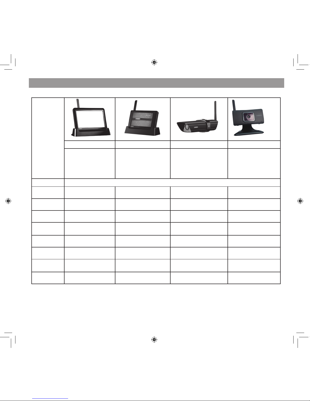
What’s in the Box?
If any items are missing or damaged, contact your place of purchase immediately.
Never use damaged products!
Need Help? Get answers at our website:
www.uniden.com.au for Australian model or
www.uniden.co.nz for New Zealand model.
7” Monitor 4.3” Monitor Outdoor Camera Indoor Camera
1x Monitor
1x Cradle
1x AC adaptor
1x Ethernet Cable
1x SD Card
1x Monitor
1x Cradle
1x AC adaptor
1x Ethernet Cable
1x SD Card
1x Camera
1x Antenna
1x AC adaptor
1x Stand
4x Mounting Screws
4x Expansion Anchors
1x Camera
1x AC adaptor
1x Stand
MODEL Quantities Of Each
G2701
1 0 1
G2710
1 1 0
G2711
1 1 1
G2720
1 2 0
G2401
1 0 1
G2410
1 1 0
G2411
1 1 1
G2420
1 2 0
GETTING STARTED
6
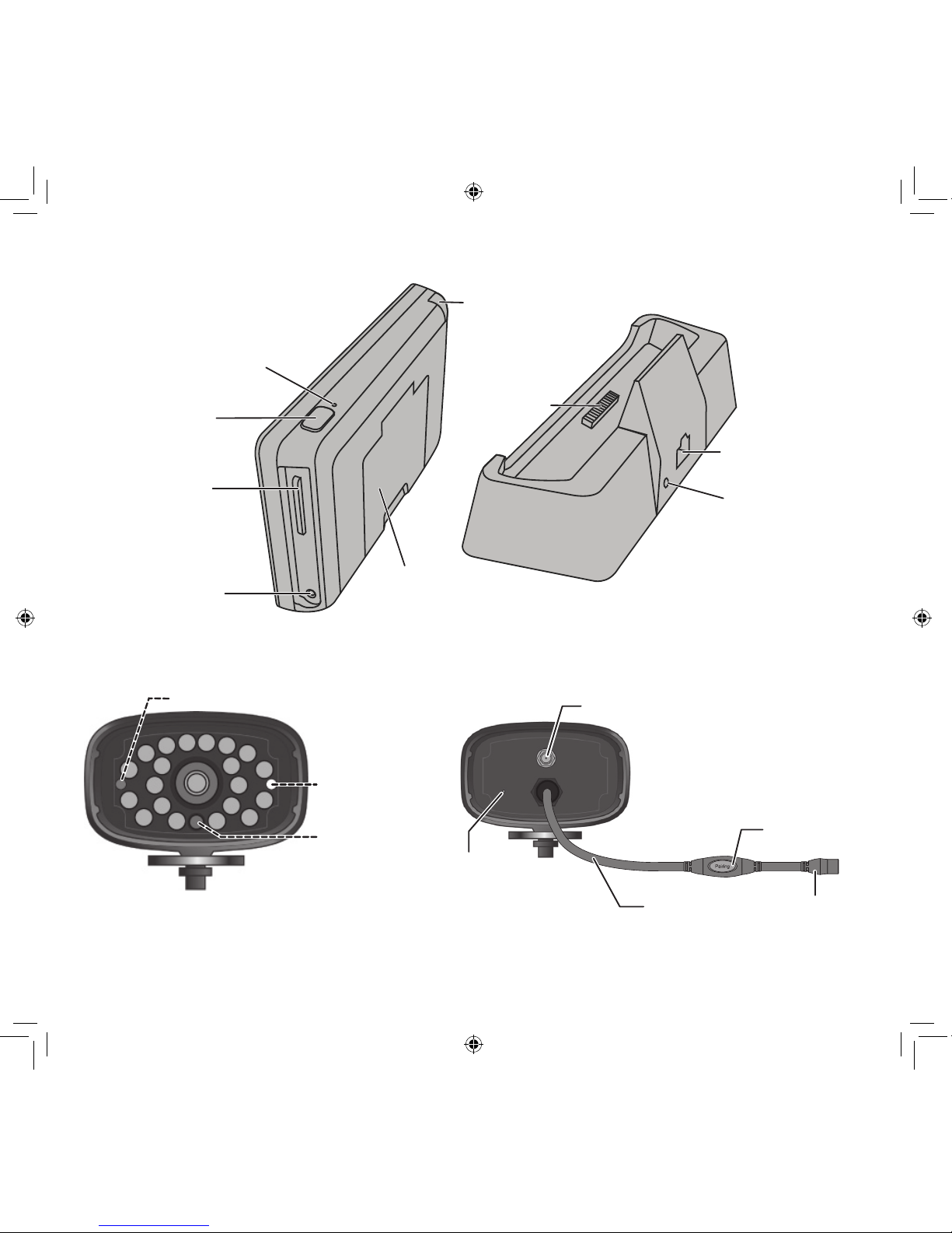
GETTING TO KNOW THE MONITOR AND THE CAMERAS
Power status
Link status
Light sensor
Front View
Back View
OUTDOOR CAMERA
Monitor-
Power Dock
Ethernet Cable
Connection
AC Power
Connection
Power
On/O
SD slot
AC Power
Connection
Monitor
(back/side)
Cradle
Pull-Out
Stand
Reset
Antenna
Back view
Antenna connector
Power pigtail
Microphone
Pair button
Power jack
7
Light State What it means?
Power Status
On The camera is on.
Off The camera is off.
Link Status
Flashing The camera is in pairing mode.
On The camera is connected to the Monitor.
Off The camera is in standby.
Charge Status
On (Green) The battery is charging.
Off The battery has charged.
What the Lights Mean?
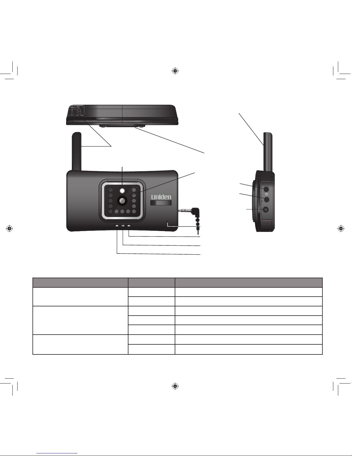
INDOOR CAMERA
LINK
POWER
Camera lens
Light sensor
Antenna (ip up)
Antenna (ip up)
Swivel stand receiver
AC adaptor
power jack
LINK
POWER LED
LINK LED
CHARGE LED
Microphone

8
Also, as dust, grime, and cobwebs accumulate on the camera glass, they can reect light from the
infrared LED and might lower video quality. Periodically clean the lens glass with a soft cloth.
The G Series outdoor camera is weatherproof and has an IP66 rating. Water can be sprayed on them
and they will still work; however, the cameras cannot be submerged underwater.
Although the outdoor cameras can be exposed directly to the rain, it is recommended that, if they
are used outdoors, they be mounted under some type of cover like a patio overhang or eave. As
rainwater drops start to dry on the camera glass, it can create spots that will reflect the light from
the infrared LEDs used for night vision, thus lowering the quality of the video.
The G Series indoor camera is not weatherproof.
General Guidelines
Mount the Camera Stand
The screen remains dark until the cameras are powered up.
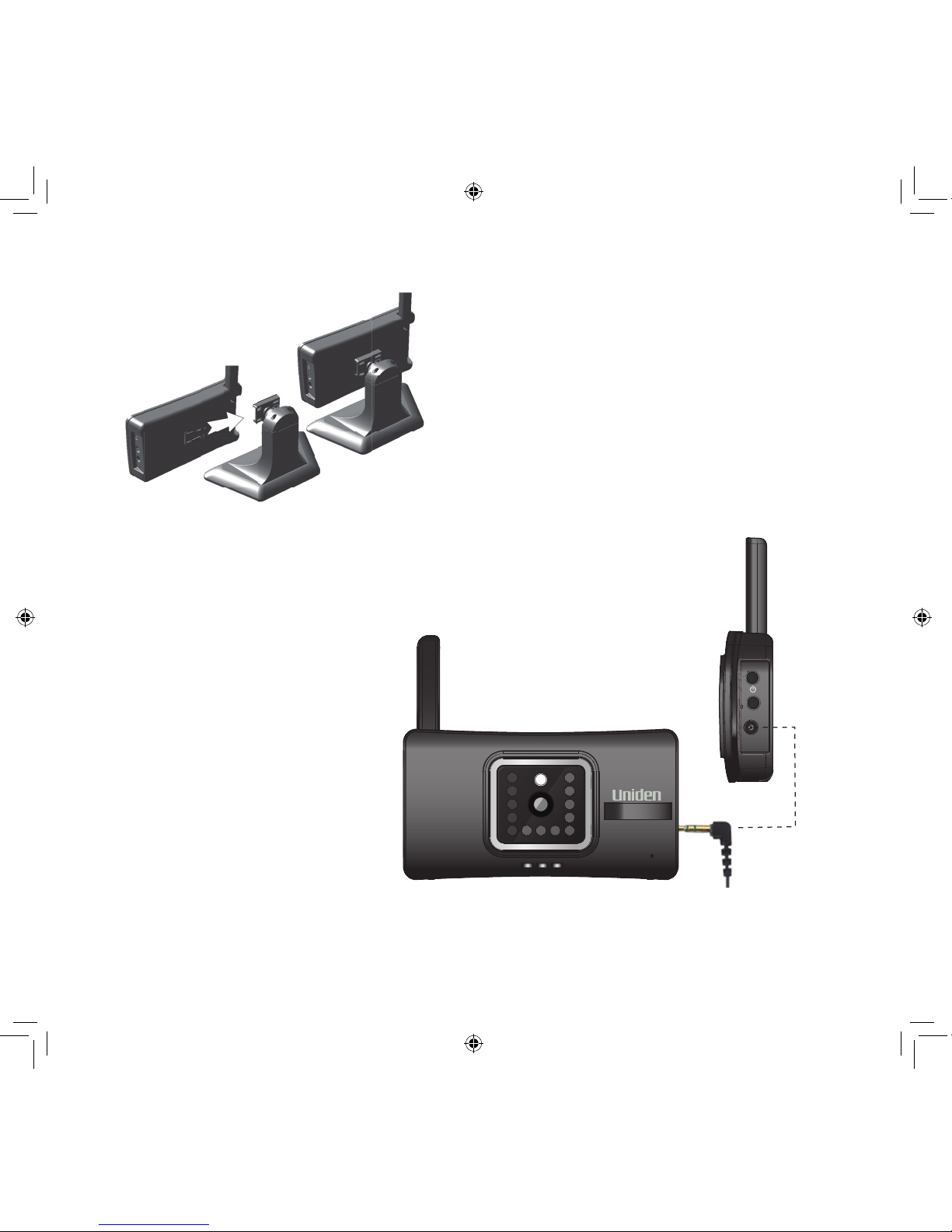
SETTING UP THE EQUIPMENT
Set Up the Monitor
1. If you are using the Monitor as a stand-alone unit, flip out the stand on the back of the Monitor,
and extend the antenna. Connect an AC adaptor to the power input on the side of the Monitor.
If you are using the Monitor in the cradle, insert the Monitor into the cradle and connect an AC
adaptor to the input on the back of the cradle.
2. Connect the other end of the adaptor to a 240 volt AC (standard indoor) power outlet.
3. Press and hold the
POWER
button on the top of the Monitor for 3 - 4 seconds to power it up.
4. The Monitor displays the Uniden
Welcome
screen for a few seconds and then transitions to the
LIVE view.

9
Placement Considerations
Consider the following when placing cameras:
• The clearest line-of-sight between the camera and monitor is best.
– Walls, especially brick and concrete, shorten the transmission distance.
– Placement next to windows allows better transmission.
• Optimized motion detection range is 1.8 - 5.5 metres for the outdoor camera. The farther away
an object is, the less accurate the motion detection.
• Avoid having a direct light source in the view of the camera, including street lights, ceiling or
oor lamps, spotlights in the driveway, etc.
• Rainfall, pool water ripples/reections, tree/shrub leaves blowing in the wind - and the shadows
they create - can generate motion detection false alarms.
You can mount the outdoor camera with the stand on the bottom (on a wall or table-top) or on the
top (on the ceiling). The indoor camera can be mounted with the stand on any at surface. When
you are positioning the camera, you might want to bring the Monitor along; it’s much easier to get
the camera into the right position when you have the display handy.
1. Hold the base of the camera stand where you want to mount it and mark the location of the
screw holes.
2. Use the included screws and anchors to attach the base to the wall or ceiling.
3. Before attaching the camera, tug gently on the stand to make sure it is securely in place.
10
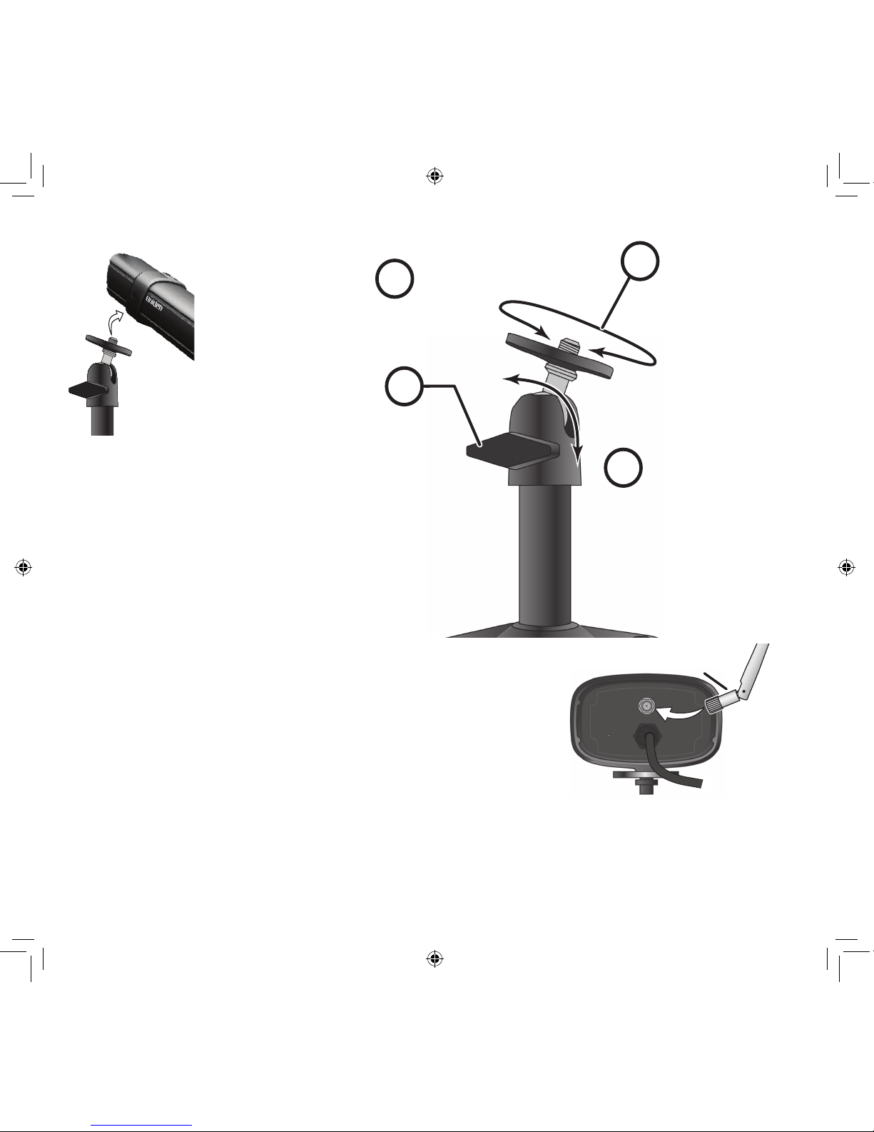
Attach The Outdoor Camera
1
2
4
3
Loosen the
wingnut to
unlock the
mounting
post.
Attach the camera
to the mounting
screw and turn it
to the desired
direction.
Adjust the post to
the correct angle,
then tighten the
wingnut to lock the
post into place.
Tighten the brace against
the camera to
secure it
in place.
Antenna
1. For each camera,
attach the camera bracket to the
mounting screw. You
can attach the stand
to the top or the bottom of the camera as
needed.Tighten it a
few turns, then turn
the camera to face
the direction you want.
5. Attach the antenna to the rear of the camera.
6. Connect one end of an AC adaptor to the camera’s power pigtail
and plug the other end into a 240 volt AC (standard indoor) power
outlet. (If necessary, connect the extension cord to the camera’s pigtail and connect the AC adaptor to the extension cord.)
Be sure the power plug and the connector are tightly twisted
together to avoid water leaking in.
7. Make sure the Power status light turns on. If it doesn’t, try reconnecting the AC adaptor, and
make sure the power outlet isn’t controlled by a wall switch.
2. Tighten the camera brace up against
the camera to secure it into place.
3. Unlock the mounting post by turning
the wingnut to the left a few turns.
4. Set the mounting post to the correct
angle, then tighten the wingnut until
the post is locked into place.
11
Attach The Indoor Camera
1. Connect one end of an AC
adaptor to the camera and
plug the other end into a 240
volt AC (standard indoor)
power outlet.
2. Make sure the Power status
light turns on. If it doesn’t, try
reconnecting the AC adaptor,
and make sure the power
outlet isn’t controlled by a
wall switch.
Slide the camera on to the stand swivel
mount until it clicks in place.
AC adaptor
power plug
LINK

12
SETTING UP YOUR SYSTEM
You can now set your cameras and system to your preferred settings.
Camera Settings
• Brightness (“G Series Settings Screen” on page 25)
• Motion Detection (“G Series Settings Screen” on page 25)
• Schedule Recordings (“Schedule Record” on page 29)
System Settings
• Power Saving (“Power Saving” on page 35)
• Screen Auto Lock (“Screen Auto Lock” on page 36)
• Time (“Time” on page 37)
• Security code (“Security Code” on page 32)
• Language (default language is English; “Changing the Language” on page 40)
Recording Settings
• Motion Detection (“Motion Detection” on page 25)
• Schedule Recordings (“Schedule Record” on page 29)
13
Your Monitor’s G Series software operates through a series of screens that let you choose groups
of operations. For example, when you tap on the camera icon in the Pop-up menus, you can set
how you want the main viewing screen - called the Live screen - to display images from the paired
cameras. You can scan between cameras, show all cameras on a single screen (Quad view), or only
display a speci c camera.
The Live screen lets you view the camera transmissions. It also lets you set up your screen display
and make adjustments to it. Icons on the screen itself let you monitor power and camera status.
The G Series system always defaults to the Live screen in Quad mode after being idle for 2
minutes while in any other system screen. This default ensures that the system is ready to record video even if you forget to return to the Live screen. The system can only start a recording while in Live screen mode.
The operation of the G24 or G27 monitor is identical. The only di erence between the two
systems is the physical size of the monitor/receiver and how you extend the antenna.
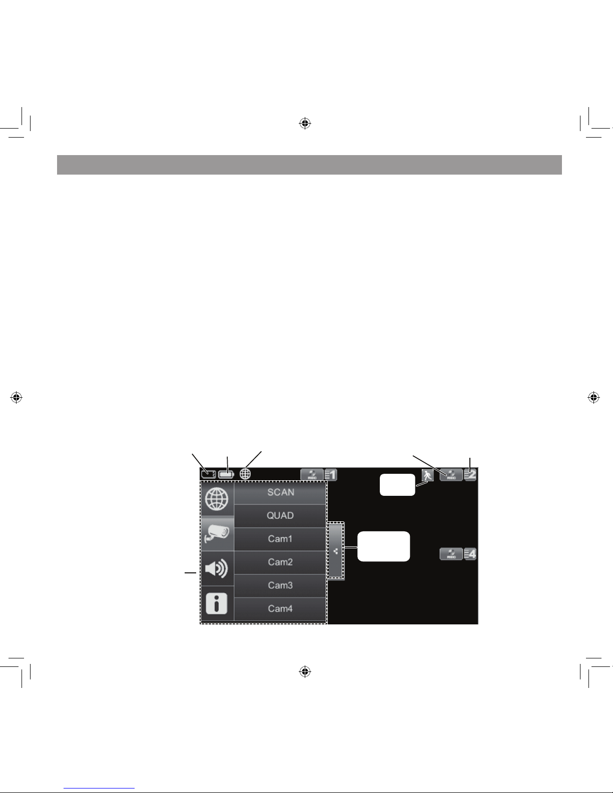
LIVE SCREEN
G SERIES SOFTWARE OPERATION OVERVIEW
SD card
status
Battery
status
Record
status
Camera number/
Signal strength
Pop up
menus
Pop up
menu tab
Motion
status
Internet
connection
status
14
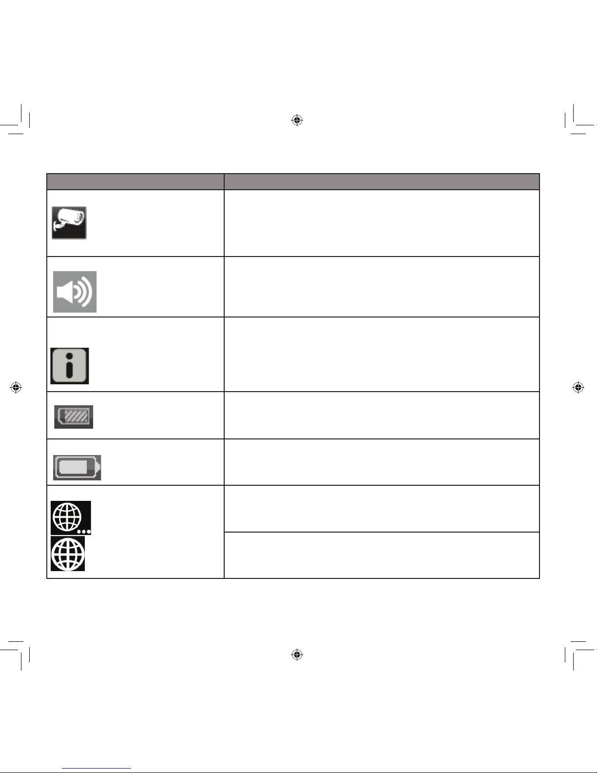
Icon What does it mean
CAMERA MODE
Select how you want the Live screen to display camera input:
•Scan between cameras (5 seconds)
•Quad view (all paired cameras display)
•Full view (1 camera displays on full screen)
VOLUME
Adjust the volume level.
G SERIES SYSTEM
SETTINGS
Access the G Series Software Operation screens or view recorded events.
SD CAPACITY
Indicates memory capacity remaining.
BATTERY CAPACITY
Displays battery capacity. This graphic shows battery at nearly
full.
INTERNET/INTRANET STATUS
Appears in LIVE view. Indicates connection to the internet is in
progress.
Appears in LIVE view and Pop-Up Menu. Indicates internet
connection is established.
What The Icons Mean
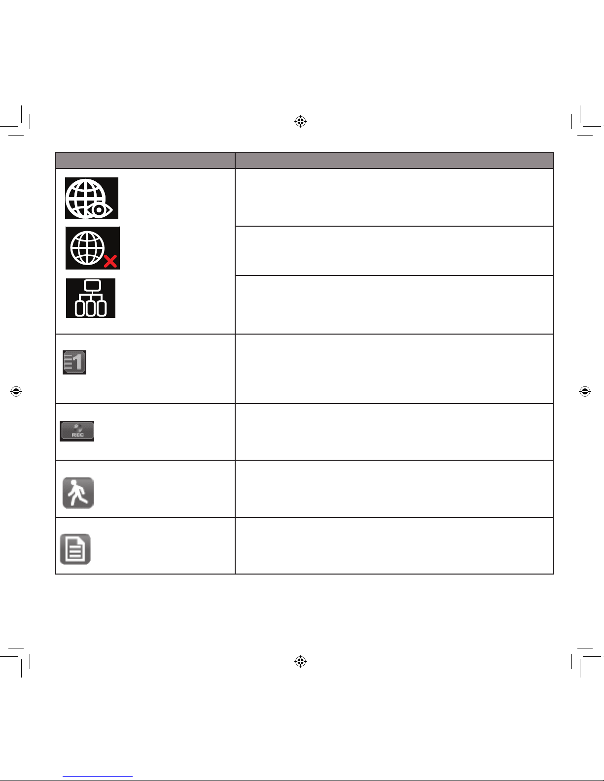
15
Icon What it does
Appears in LIVE view. Indicates remote viewing in progress.
Appears in LIVE view. Indicates system not connecting to internet.
Appears in LIVE view. Indicates the intranet connection is established.
CAMERA NUMBER
Displays the camera number and signal strength through the
status lines to the left of the number.
RECORD STATUS
•Tap to start or stop recording for that camera
•Steady on - Not recording
•Flashing - Recording
MOTION
System indicates motion detection recording in progress.
SCHEDULED
System indicates scheduled recording in progress.
16
Icon What it does
POP UP MENU TAB
Opens and closes the pop up menu display.
NO SD CARD INDICATOR
Displays red when the SD card is not present or is damaged.
17
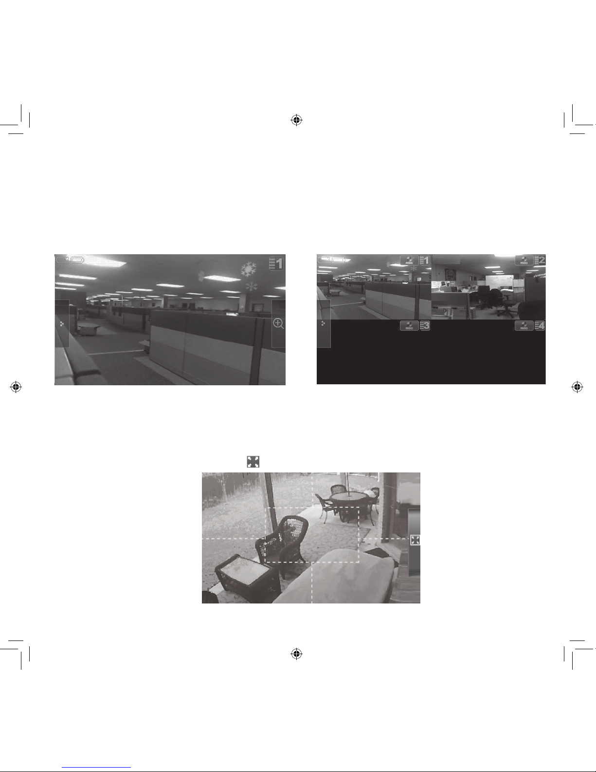
Changing How the Live Screen Displays
The Live screen displays in 2 views - Quad View or Full View. Quad View divides the screen’s image
area into 4 quadrants and displays camera video in each quadrant. If less than 4 cameras are on,
only those cameras’ video will display on the Live screen.
Full view displays a single camera’s video on the entire screen. If you are in Quad View, tap on the
camera quadrant you want to expand to Full View. Tap on that image to return to Quad View.
Using the Pentazoom™ Feature
While in any camera’s full screen view, selecting the + icon on the right side of the screen enables
the PentaZoom feature. PentaZoom lets you select from 5 sections of the video image. Tap on a
section and it will digitally zoom to full screen. Tap on the video to return to full screen mode or to
go back to the PentaZoom screen, tap .
18
USING YOUR SYSTEM
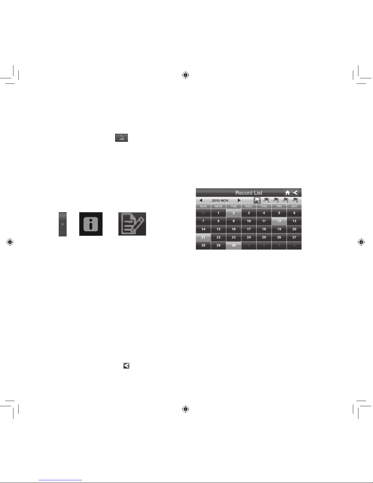
Recording Live Video
1. On the Live screen, tap
for the camera to begin recording.
2. Tap it again to stop recording.
You can record from all cameras at the same time.
Playing Back Recorded Video
From the pop-up menus, tap
the following icons as they
appear on the screens:
The Record List screen displays.
1. Tap on the highlighted day containing the recording you want to view or on a specific camera
to only view that camera’s recordings. The Record List screen displays those recordings listed
in a folder.
If you tap on a day that is not highlighted, a folder displays with no recordings listed.
2. Tap on the recording you want to view. It displays on the screen.
3. Tap on any area of the screen that does not have control icons to bring up the playback
progress bar. Tap that area again to close it.
4. While playback progress is visible, you can fast forward/rewind by dragging the playback bar
forwards or backwards.
5. When playback ends, tap to return to the Record List.
You can delete a recording by tapping X, next to the camera icon.
Recordings are saved to the SD card (approximate recording time per GB is 225 minutes).
The SD card must be installed for recording to begin.
On the playback progress bar, tap the double arrow to skip forward or backwards about 10 seconds. Tap the arrow and bar to skip to the next or previous video.
19
Adding New Cameras
Your Monitor supports a total of four active cameras at a time. When you add a camera, you have to
pair it to the Monitor (that is, you have “introduce” the camera and Monitor so they can communicate).
• If a camera is already assigned to the selected channel, the Monitor overwrites that camera link
with the new one.
• Only pair one camera at a time! The Monitor links to the rst camera it detects. If two or more
cameras are in pairing mode, you can’t control which camera the Monitor will detect rst.
SOME THINGS TO KNOW ABOUT PAIRING CAMERAS
PAIR CAMERA
1. From the Pairing Camera screen (see “Pairing” on
page 23), tap the camera image you want to pair. A
processing icon displays for a 60 second countdown.
2. During the 60 second countdown, quickly press and
release the Pairing button on that camera’s power
cord (see ”Pairing” on page 23).
3. The system automatically adjusts the Camera On
screen accordingly.
4. If you have any trouble, consult the the table on page 20.
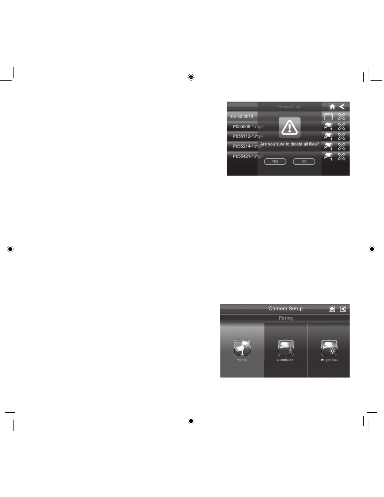
Deleting Recorded Files
You can delete a single recorded le or a folder containing
all recorded les for a speci c day.
1. On the Record List screen (see previous Record List
screen), tap the day with recorded files you want to
delete. The list of recorded files displays.
2. Tap the X on the right-hand side of the entry. If you are
deleting a folder, a confirmation screen displays. If you
are deleting a single recorded file, that file deletes without a confirmation required.
20
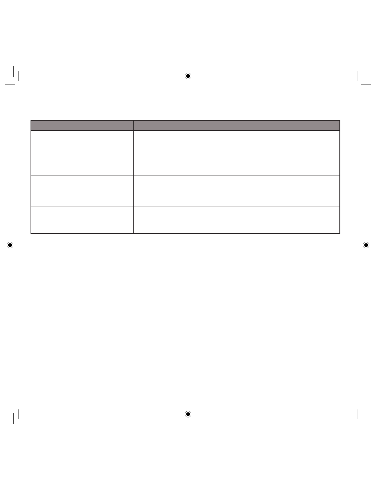
TROUBLESHOOTING CAMERA PAIRING
Consult the following table for camera pairing troubleshooting suggestions:
If... Try...
the camera’s signal status icon
shows no bars
•making sure the camera is plugged in and the red LED is on.
•making sure that the camera’s antenna is attached and the
Monitor’s antenna is extended.
•making sure the camera is paired to the correct channel
•re-pairing the camera and Monitor
the camera’s signal status icon
shows one or two bars or the
video quality is poor
See “General Guidelines” on page 8 for tips on improving video
quality.
the camera won’t pair with the
Monitor
•making sure the camera is plugged in and the red LED is on.
•pressing and releasing the pairing button quickly. Do not press
and hold the pairing button.
 Loading...