

Page 1

Page 2

INTRODUCTION
Welcome to the world of sophisticated,
microprocessor controlled CB radio com
munications. Your Uniden PRO 31 Oe repre
sents the most advanced porta ble/mobile
radio ever designed for use in the Citizens
Band Radio Service. It will operate on any
of the 40 AM frequencies authorized by
the Department of Communications, Your
PRO 31 Oe features a superheterodyne cir
cuit with PHASE LOCK LOOPtechnrquesto
assure precise frequency control. It can be
powered by your vehicle battery or with
the snap-on battery pack (batteries not in
cluded). This radio has been type acccepted
and certified by the D.O.C.
WARNING
Before transmitting with your transceiver,
you must obtain a Department of Commu
nications (D.O.C.) Citizens Radio Licence.
Obtain an application form, from the
D.O.C. Before completing the form you
should read the conditions governing the
licensing and operation of the C.R.S,
(D.O.C, brochure RB 14). This brochure al
so can be obtained from the D.O.C. After
completing the application form, mail it
with the appropriate fee to the Superin
tendant Regulatory of Licensing in the
State or territory in which the station will
be operated.
Page 3
INSTALLATION
MOBILE INSTALLATION
Plan the location of the radio and micro
phone bracket before starting instailation,
Seiect a location that is convenient for op
eration and does not interfere with the
driver or passenger in the vehicie. The mic
hanger bracket shouid be secureiy
fastened to a soiid surface using the seif
tapping screws which are provided. The
button on the back of the radio wiil siide
into the mic hanger to hoid it secureiy in
place.
Mobile Antenna
Since the maximum allowable power out
put of the transceiver is limited by the
D.O.C, the antenna is a very important fac
tor afferting transmission distance. The
magnetic mount base and screw-in teles
copic antenna will provide maximum range
when properly installed.
Screw the antenna into the base. Place the
base on a flat metallic area of your vehicle
roof. The center of the roof is ideal for 360“
transmission. Feed the coaxial cable thru a
window or door. With the battery pack off,
connect the antenna to the bottom of the
unit.
If another external antenna is desired con
sult your local CB Dealer for a com
patible model. You have purchased a
superior quality transceiver. Don't diminish
its performance by installing an inferior
antenna.
Only a properly matched antenna system
will allow maximum power transfer from
the 50-ohm transmission line to the radiat
ing element. We recommend that you
have your system checked with an SWR
meter when installing your antenna. Vbur
local dealer is qualified to assist you in
the selection an installation of a proper
antenna to meet your application
requirements.
Connecting the Power
Connect the power cord to the jack on the
bottom of the unit [battery pack must be
removed). Plug the cord into the cigarette
lighter of your vehicle. The PRO 31 Oe may
also be connected directly to the fuse
block with the proper wiring (not
included).
IMPORTANT - The cigarette lighter plug
is designed to be used with negative
ground vehicles. Do not attempt to oper
ate the unit with the power cord con
nected to a positive ground vehicle.
Ground Information
Most newer cars and smali trucks use a ne
gative ground system, while some older
cars and some newer, larger trucks may use
a positive ground system. A negative
ground system is generally identified by the
" battery terminal being connected to
the vehicle motor block. If you cannot de
termine the polarity ofyour vehicle, consult
your vehicle dealer for information.
Positive Ground System
If you are operating on a positive ground
system, the unit must be wired directly to
the fuse block. Connect the black lead
from the radio to the negative bat
tery terminal or other convenient point
and connect the red power lead to the
chassis or vehicle frame, or the positive
" + " terminal of the battery.
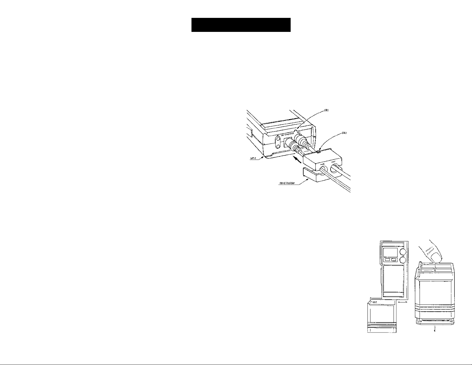
Cord Holder
install the cord holder with ANT. iabei
on right-hand side and PWR. Iabei on
left-hand side as shown. Match key (A)
with notch (B) as illustrated.
While pressing the cord-holder's upper
and lower sides, insert the cord holder
securely into the grooves at the bottom
ofyour PRO 31 Oe. Cord holder will snap
into place when pressure is released.
PORTABLE USE
The PRO 3I0e can operate under its
own battery power. The snap-on bat
tery pack included withyour unit makes
it a true Emergency CB. It also makes a
great portable CB for long range com
munications outdoors.
Installing the Batteries and Bat
tery Pack
Hold the battery pack in one hand and
press on the top of the pack where indi
cated. The battery holder will slide out.
install 8 "AA" size nonrechargeable
batteries. Slide the battery holder back
into the battery pack until it is flush
with the bottom. Slide the battery pack
onto the bottom of the radio from left to
right until it snaps in place. Make sure
the slots on the battery pack and the ra
dio fit correctly.
NOTE: When the batteries become weak
the battery LED will light. Be sure to
replace the batteries as soon as possible.
You can preserve battery power by select
ing the LOW position on HI/LOW switch.
The LOW setting has substantially shorter
transmission range.
Connecting the Antenna
For portable use the telescopic antenna
will give good results. Simply unscrew it
from the magnetic mount base and
screw it into the antenna connector on
the top of the unit. Fully extend the an
tenna for maximum range.
HI/LOW Switch
The PRO 3I0e has a transmission power
selector switch - HI/LOW. In the HI posi
tion the unit win transmit at the higher
output power and achieve longer range.
In the LOW positron the transmission
output power (range) is substantially
reduced; however, the battery life will be
increased. For longer range select the HI
position. For maximum battery life select
the LOW position.
Page 4

CONTROLS AND FUNCTIONS
?. Instant CH 9 - Select CH 9 position
to instantly select the Emergency
channel. Switch back to return to
normal 40 channel operation.
2. TX Indicator * An LED lights to indi
cate when the radio is transmitting.
3. Battery Low LED - Lights when the
batteries in the snap-on battery pack
need to be replaced.
4. Built-in Mie - A professional quality
microphone built into the unit. The
push to talk switch is conveniently
located on the side of the unit,
5. Channel Display - A large LED dis
play shows the channel currently in
use.
6. Channel Selector - Up and Down
electronic channel keys makes it easy
to select any of the forty channels.
Press once to change one channel.
Press and hold to rapidly change
channels.
7. IMPORTANT - All channels except
channel 9, may be used for normal
communications. Channel 9 has been
reserved by the D.O.C. for emergency
communications involving the imme
diate safety of Individuals or the pro
tection of property. Channel 9 may al
so be used to render assistance to a
motorist. This is a D.O.C. rule and ap
plies to all operators of CE radios.
8. Squelch Control - The Squelch con
trol is used to eliminate background
noise during the absence of a trans
mission. Turn the control fully counter
clockwise, then slowly rotate it back,
clockwise until all noise disappears. At
this setting any transmission must be
slightly stronger than the background
noise to "Break Squelch” and to be
heard. Further clockwise rotation will
increase the threshold at which a sig
nal will be heard. You can select any
level to "Break Squelch".
9 Volume with Power On/Off
Control - Turn the unit on and adjust
the volume.
10. HI/LOW Switch - Select the LOW
position for short transmission range
or to conserve battery power. Select
the HI position for longer range.
J). Power Cord - The power cord with
cigarette lighter plug includes a fuse. |
12 Magnetic Mount Antenna - A
telescopic magnetic mount antenna
attaches to most any vehicle. The 16' |
coaxial cable connects directly to the
unit.
13. Portable Antenna Connector -
This female connector permits con
nection of the telescopic antenna for |
portable use. |
14. Mobile Antenna Connector -
Connect the coaxial cable from the
magnetic mount antenna for mobile
use.
15. Power Connector - Connect the
fused cigarette lighter power cord.
16. Snap-on Battery Pack - Over
40% of vehicle trouble is related to
battery failure. The PRO 310e
comes complete with a snap-on bat
tery pack [batteries not included).
Essential equipment for every vehi
cle. Thebatterypackalsoallowsyou
to take your radio anywhere you
.■ . ■ . " ■■ .
want to go - providing long range
communications.
17. Cord Holder - Your PRO 31 Oe in
cludes a special cord holder to pre
vent the Antenna cord and the Pow
er cord from getting loose.
18. Protective Case - The attractive
vinyl case neatly stores ail compo
nents when not in use.
V-
---
Si
- -V^.- -7-.. ^'i
Page 5

OPERATION
OPERATING PROCEDURE
TO RECEIVE
1. Be sure that the power source, antenna
and microphone are properly
connected.
2. Turn the unit on by rotating the Volume
control clockwise,
3. Set the channel selector switch to the
desired channel,
4. Set the Volume control to a comfort
able listening level.
5. Listen to the background noise from
the speaker. Turn the Squelch control
clockwise until the noise disappears (no
signal should be present]. Leave the
control at this setting. The squelch is
now properly set. The receiver will re
main quiet until a signal is actually
received. Do not advance the cohtrol
too far, or some weaker signals will not
be heard.
NOTE: The PRO 31 Oe has a unique power
saving feature that is particularly impor
tant when operating with the battery
pack. The channel display will auto
matically turn off if the unit is neither
transmitting nor receiving [Squelched).
Since the channel display uses a sub
stantial amount of power this feature will
effectively prolong the life of your
batteries.
OPERATING PROCEDURE
TO TRANSMIT
1, Be sure the operator has read and
understands D.O.C, rules and regul
ations prior to operating the transmit
ter.
2, Check the HI/LOW switch for proper
setting,
3. Select the desired channel for trans
mission.
4. If the channel is clear, depress the push-
to-talk switch on the side of the unit
and speak into the microphone with a
normal voice.
IMPORTANT NOTICE
Tour portable CB radio has been designed
to transmit at 4 wats output power when
connected to your vehicle battery. When
used with the battery pack, the transmit
power may be lower. The quality of the
batteries used in the battery pack will also
have an affect on the output power. For
best results use the optional NiCad battery
pack - BPS 1OC and B10 NiCad batteries or
good quality alkaline batteries
Page 6

SPECIFICATIONS
Channels: 40 AM
Freguency Range;
Frequency Control:
Frequency Tolerance; +/-0.005%
Operating Temp.:
Microphone:
Input Voltage:
Current Drain: TX: full mod., 1.4A
Size;
Complete Package:
Antenna Connector:
TRANSMITTER
26.965 to 27.405 MHz
Phase Locked Loop (PLL) synthesizer
-30"C to +50°C
Built-in type: electric
12.0 VDC nom. (-ground)
RX: with max audio output, 0.5A
2^/g“Wx V/2~D X 572”H
2 lb. 8 oz.
RCA Pin Jack
Power Output:
Modulation: Class B amplitude modulation
Freq. Response; 300 - 3000 Hz
Output Impedance: 50 ohms, unbalanced
Selectable HI or LOW
RECEIVER
Sensitivity:
Selectivity:
Image Rejection;
I.F Frequency;
Automatic Gain Controi
Squelch:
Audio Output Power;
Freq. Response:
Distortion:
Internal Speaker:
SERVICING YOUR CB
Technical information, diagrams and charts
will be provided upon request. It is the
user's responsibility to see that this radio is
operating at all times in accordance with
the D.O.C Citizens Band Radio Service
regulations. We highly recommend that
0.7fiV for 1 OdB; (S + N)/N typical
6dB (a 7KHz, 70dB (a 1 OKHz typical
75dB typical
Double Conversion Superheterodyne
1st 10.695 MHz
2nd 455 KHz
(AGC): less than lOdB change in audio output for inputs
from 10 to 50,000 microvolts
Adjustable; threshold less than 1 |jlV
0.5 watts max. into 8 ohms
300 to 2500 Hz
less than 10% at 0.4 watts, lOOOHz
16 ohms, 0.4 watts round
you consult a gualified radiotelephone
technician for service and alignment of this
radio. When ordering parts, it is important
to specify the correct model number and
serial number of this radio.
Please refer to the WARNING information
on the first page of this manual.
Page 7

TROUBLE SHOOTING
If your PRO 3I0e is not performing up to
your expectations, please try these simple
steps. If you still cannot get satisfactory
results after reading this manual and fol
lowing the troubleshooting steps, please
call your local dealer.
TROUBLE
Unit will not turn on. I. Check power cord and all
No power connections
Poor reception
Weak transmission
CHECK
2 Check power cord fuse.
3.
Check vehicle electrical
system.
4. Check battery pack
connection.
5, Check if batteries are
weak.
1. Check and adjust Squelch.
2. Check antenna system and
cable, connectors,
3. Make sure antenna is
fully extended.
4. Check operation mode of
the radio.
1. Check antenna system and
cable, connectors.
2. Make sure antenna is
fully extended.
3. Check antenna grounding.
4. Check for corrosion on
connectors.
If you determine that service is necessary
contact your local dealer or pack the unit
in its original carton. Send it along with a
brief, concise description of the problem,
your name, address, phone number, and a
copy of the original purchase receipt to
the address listed in the warranty.
Page 8

WARRANTY
TWO YEAR LIMITED WARRANTY
WARRANTOR. UNIDEN AUSTRALIA PTY LTD 345
Princes Highway, Rockdale, N.S.W. 2216
I'UNIDEN";.
ELEMENTS OF WARRANTY. UNIDEN warrants, for
the duration of this warranty, its UNIDEN CB Product
to be free from defects in materials and craftsmanship
with only the limitation or exclusions set out below.
WARRANTY DURATION. This Warranty shall termi
nate and be of rra further effect Two |2) years after the
date of original purchase of the Product or at the time
the Product is |a) damaged or not maintained as
reasonable and necessary, jb) rrvxlified, |c) improperly
installed, (d) Is repaired by someorte other Warrantor
for a defect or malfunction covered by this Warranty, or
(e| used in a manner or purpose for which the Product
was not intented.
PARTS COVERED. This Warranty covers all compo
nents of the Products.
STATEMENT OF REMEDY. In the event that the
Product does not conform to this Warranty at anytime
while this Warranty Is effective. Warrantor will repair
the defect and return it to you prepaid, without
change for parts, service, or any other costs incurred by
Warrantor or its representatives in connection with the
performance of this Warranty In addition, if the
Product contains a defect or malfunction which is not
repaired after a reasonable number of attempts by
Warrantor to repair the Product, the Product or
defective component will at our discretion, be replaced
without charge, when the defective product is deli
vered to the warrantor at 345 Princes Highway,
Rockdale. N S W. 2216 free and clear of all liens and
encumbrances. Please note that while the Pnaduct will
be remedied under this Warranty without charge. THIS
WARRANTY DOES NOT COVER OR PROVIDE FOR
THE REIMBURSEMENT OR PAYMENT OF INCIDEN
TAL OR CONSEQUENTIAL DAMAGES,
PROCEDURE FOR OBTAINING PERFORMANCE
OF WARRANTY, In the event that the Product does
not conform to this Warranty, the Product should be
shipped prepaid, to Warrantor at 345 Princes High
way, Rockdale, N.S.W. 2216, THE ORIGINAL OR
COPY OF THE SALES RECEIPT OR OTHER VALID
EVIDENCE OF THE DATE OF THE ORIGINAL PURCEIASE MUST ACCOMPANY THIS PRODUCT.
UTUA013I1CA(SK)
345 Princes Highway, Rockdale,
BRISBANE
3/12 Randall StreeL
Slacks Creek,
Old 4127
Phone (07) 290-1I8S
Fax|07) 808 4251
MELBOURNE
446-448 Bell Street,
East Preston,
VIC 3072
Phone (03) 484 0373
Fax (031 484 6057
& TASMANIA
uniden*
Australia Pty. Ltd,
HEAD OFFICE :
N.S.W. 2216
Phone: 599 3355
Fax: (02) 599 7657
PERTH
23 Geddes Street
Balcatta,
WA. 6021
Phone (09) 344 3937
Fax (09) 349 8165
ADELAIC£
72-74 Halifax Street
Adelaide
SA. 5000
Phone (08) 223-4235
Fax (08) 223 1471
Printed in the Philippines
 Loading...