

Page 1

Operating instructions
Hydraulic workshop press
WPP 15 E
WPP 15 E
WPP 15 E
Page 2

Publication details
Contents
Product identification
Hydraulic workshop press Item number
WPP 15 E 630 0016
Manufacturer
Stürmer Maschinen GmbH
Dr.-Robert-Pfleger-Str. 26
D-96103 Hallstadt
Germany
Hotline: 0049 (0) 900 19 68 220
(0.49 Euro from German landlines)
Fax: 0049 (0) 951 - 96555-55
email: info@unicraft.de
URL: www.unicraft.de
Publication details..................................................... 2
1 Introduction .............................................................3
1.1 Copyright............................................................ 3
1.2 Customer service................................................ 3
1.3 Disclaimer........................................................... 3
2 Safety....................................................................... 3
2.1 Legend of symbols............................................. 3
2.2 Operator responsibility ....................................... 4
2.3 Operating staff qualification ............................... 4
2.4 Personal protective equipment........................... 5
2.5 Safety identifications on the workshop press ..... 5
3 Intended use ............................................................6
3.1 Foreseeable misuse ........................................... 6
3.2 Remaining risks .................................................. 6
4 Technical data .........................................................6
4.1 Table................................................................... 6
4.2 Environmental conditions ................................... 6
4.3 Type plate........................................................... 7
4.4 Pressure gauge .................................................. 7
5 Transport, packaging, storage...............................7
6 Machine description................................................8
7 Setup ........................................................................8
8 Installation ...............................................................8
8.1 Installing the crossbeam feet and press table ... 9
8.2 Installing the pump unit ...................................... 9
8.3 Installing the pressure gauge............................. 9
Information about the operating instructions
Genuine operating instructions
Edition: 24 March 2016
Version: 1.02
Language: English
Author: DM
Copyright information
Copyright © 2016 Stürmer Maschinen GmbH, Hallstadt,
Germany.
Stürmer is the sole owner of the content of these operating instructions.
Forwarding and reproduction of this document as well
as use and notification of its content is not permitted
without explicit consent. Infringements shall oblige to
payment of compensation.
9 Before commissioning..........................................10
10 Operation .............................................................10
10.1 Adjusting the table height............................... 10
10.2 Setting up the work area................................. 11
10.3 Adjusting the horizontal working position....... 11
10.4 Aligning hydraulic cylinders ........................... 11
10.5 Building up pump pressure............................ 11
10.6 Marking the cylinder limit position.................. 11
10.7 Retracting hydraulic cylinders........................ 12
10.8 Processing the workpiece .............................. 12
11
Maintenance and repairs
11.1 Cleaning maintenance.................................... 13
11.2 Maintenance and repairs................................ 13
12
Disposal, reusing used machines
12.1 Decommissioning........................................... 15
12.2 Lubricant disposal.......................................... 15
.....................................13
.......................15
13 Liability for defects (warranty)...........................16
14 Spare parts...........................................................17
14.1 Spare parts orders.......................................... 17
14.2 Spare parts drawings ..................................... 18
14.3 Hydraulics circuit diagram ............................. 20
15 EU Declaration of Conformity ............................21
Subject to technical modifications and changes.
2 WPP 15 E | Version 1.02
Page 3

Introduction
1Introduction
You have made an excellent choice in purchasing a Unicraft hydraulic workshop press.
Carefully read the operating instructions prior to commissioning.
They describe correct commissioning, intended use
and safe as well as efficient operation and maintenance
of your hydraulic workshop press.
The operating instructions form part of the hydraulic
workshop press. Keep these operating instructions at
the installation location of your hydraulic workshop
press. Please also note the locally applicable accident
prevention regulations and general safety regulations
for the use of hydraulic workshop presses.
1.1 Copyright
The contents of these operating instructions are protected by copyright. Their application is permitted within
the context of the use of the hydraulic workshop press.
Any further use shall not be permitted without written
consent by the manufacturer.
1.2 Customer service
1.3 Disclaimer
All data in these operating instructions has been compiled on the basis of the state-of-the-art, valid standards
and guidelines as well as our many years of expertise
and experience.
The manufacturer shall not be liable for damage in the
following cases:
- Non-observance of these operating instructions
- Unintended use
- Deployment of untrained staff
- Conversions at one's own responsibility
- Technical modifications
- Use of unauthorised spare parts
The actual scope of delivery may deviate from the descriptions and illustrations in this document as a result of
special variants, optional extras or recent, technical
modifications.
The obligations defined in the supply contract shall apply in addition to the general terms and conditions and
the manufacturer's general terms and conditions as well
as the statutory regulations valid at the time of the conclusion of the contract.
Please contact your specialist retailer if you have any
questions regarding your workshop press or require any
technical information. Your specialist retailer will be
happy to support you with specialist advice and information.
Germany:
Stürmer Maschinen GmbH
Dr.-Robert-Pfleger-Str. 26
D-96103 Hallstadt
Germany
Repair service:
Hotline: 0049 (0) 900 19 68 220
(?0.49 from German landlines)
Fax: 0049 (0) 951 96555-111
Email: service@stuermer-maschinen.de
Spare parts orders:
Fax: 0049 (0) 951 96555-119
Email: ersatzteile@stuermer-maschinen.de
Please submit any information and experiences you
make during application of the machine as these may
be valuable for product improvements.
2 Safety
This section provides an overview of all important safety
packages for personal protection as well as safe and reliable operation. The sections on individual service life
phases contain additional, specifically applicable safety
information.
2.1 Legend of symbols
Safety instructions
Safety instructions in these operating instructions have
been highlighted with symbols. Safety instructions are
indicated by signal terms that express the degree of risk
involved.
DANGER!
This combination of symbol and signal term indicates a directly dangerous situation which may
cause death or serious injury if not averted.
WPP 15 E | Version 1.02 3
Page 4

Safety
WARNING!
This combination of symbol and signal term indicates potentially hazardous situations which may
cause death or serious injury if not averted.
ATTENTION!
This combination of symbol and signal term indicates a potentially hazardous situation which may
cause minor or light injuries if it is not averted.
IMPORTANT!
This combination of symbol and signal term indicates a potentially dangerous situation which may
cause material damage or harm the environment if it
is not averted.
NOTE!
This combination of symbol and signal term indicates
a potentially dangerous situation which may cause
material damage or harm the environment if it is not
averted.
Tips and recommendations
Obligations of the operator:
If the machine is used for commercial purposes, operators are subject to the legal stipulations in terms of occupational safety. For this reason, the safety instructions in
these operating instructions as well as the safety, accident prevention and environmental protection regulations valid at the installation location must be complied
with. In this process, the following shall apply in particular:
- Operators shall obtain information about valid occupational safety regulations and determine additional hazards as part of a risk assessment which
result from the specific operating conditions at the
machine's installation location. Said risk assessment shall be reflected in operating instructions for
machine operation.
- During the entire machine operating time operators must check whether the operating instructions
they created meet current standards and adapt
the operating instructions where necessary.
- Operators shall clearly manage and specify the responsibilities for installation, operation, troubleshooting, maintenance and cleaning.
- Operators must make sure that all persons handling the machine have read and understood
these operating instructions. Operators must also
regularly train staff and notify of the hazards.
- Operators shall provide staff with the required protective equipment and wearing the required protective equipment shall be mandatory.
Tips and recommendations
This symbol highlights useful tips and recommendations as well as information for efficient and reliable
operation.
Observe the safety information in these operating instructions to minimise the risk of personal injury as well
as material damage and prevent hazardous situations.
2.2 Operator responsibility
Operators are defined as the persons who operate the
machine for commercial or profit-based purposes or
provide the machine to third parties for use or application and bear the legal product responsibility in terms of
the protection of users, staff or third parties during operation.
Operators shall also be responsible for maintaining the
machine in a technically perfect condition. For this reason, the following shall apply:
- Operators shall make sure that the maintenance
intervals described in these operating instructions
are complied with.
- Operators shall regularly check that the safety
equipment is fully functional and complete.
4 WPP 15 E | Version 1.02
Page 5

Safety
1
2
2.3 Operating staff qualification
The different tasks described in these operating instructions require different levels of skills in terms of the qualifications of operating staff working with the machine.
WARNING!
Risk from inadequately qualified persons!
Inadequately qualified persons are unable to assess
the risks when handling the workshop press, thus
putting themselves and others at risk of severe or
fatal injuries.
- All work must be carried out by qualified persons
only.
- Keep inadequately qualified persons away from the
work area.
Exclusively persons of whom it can be expected that
they reliably complete assigned tasks shall be authorised to carry out any tasks. Persons whose reactions
have been impaired shall not be authorized, e.g. drug
users, users under the influence of alcohol or medication.
These operating instructions specify the following personal qualifications for the different tasks:
Operating staff:
The personal protective equipment is described in the
following section:
Protective goggles
Protective goggles are intended to protect the eyes
from flying parts.
Protective gloves
Protective gloves are intended to protect the hands
from components with sharp objects as well as friction, abrasion, and deep-cut injuries.
Safety shoes
Safety shoes protect feet from pinching, falling parts
and slipping on slippery surfaces.
Protective clothing
Protective clothing is tight-fitting work clothing without protruding parts, usually with a low tear resistance.
Operating staff has undergone an induction by the operator about the entrusted tasks and potential hazards resulting from improper behaviour. Operating staff shall
exclusively be permitted to carry out any tasks beyond
operation in normal mode if this has been specified in
the operating instructions and operators have explicitly
entrusted operating staff with the task.
Specialist staff:
As a result of specialist training, expertise, experience
and skills in terms of the relevant standards and regulations, specialist staff is able to complete the tasks they
are entrusted with and independently identify hazards
and avert risks.
Manufacturer:
Certain work must be carried out by manufacturer specialist staff only. Other staff is not permitted to carry out
this work. Contact our customer service to have the work
carried out.
2.4 Personal protective equipment
Personal protective equipment is intended to protect the
health and safety of persons at work. Staff must wear the
personal protective equipment indicated in individual
sections of these operating instructions when carrying
out the different tasks on the machine.
2.5 Safety identifications on the workshop press
The following safety identifications have been attached
to the workshop press (Fig. 1) which must be observed.
Fig. 1: Safety identifications
1 Pinching hazard for the upper limbs |
2 Safety information: read operating instructions, wear eye protection,
wear protective clothing and safety shoes
Safety identifications attached to the machine must not
be removed. Damaged or missing safety identifications
may cause errors, personal injury and material damage.
They must be replaced immediately.
If the safety identifications are not visible and comprehensible at first glance, the machine must be stopped
until new safety identifications have been attached.
WPP 15 E | Version 1.02 5
Page 6

Intended use
3 Intended use
The hydraulic workshop press is intended for use in the
automotive and mechanical engineering industry only. It
is suitable for pressing in/out bearings, bushes, embossing, deformation and stamping. The capacity
stated in the technical data must not be exceeded. Do
not apply excessive force to workpieces. Check pressure loads on the pressure gauge.
The hydraulic workshop press must be operated by persons who have been instructed on the use of the machine only.
The intended use shall also include adherence to all information in these operating instructions. Any other use
or use beyond the intended use shall be deemed misuse.
WARNING!
Risk of misuse!
Misuse of the machine may cause hazardous situations.
- Operate the machine within the performance range
stated in the technical data only.
- Do not bypass or disarm safety equipment.
- The workshop press must be operated in technically perfect condition only.
All persons working with the workshop press must be
aware of the remaining risks and observe the instructions to prevent these remaining risks from causing accidents or damage:
- Risk of pinching upper limbs during operation
- It may be necessary to remove installed protective
equipment to configure and equip the machine.
This causes various remaining risks and potential
hazards each user must be aware of.
4 Technical data
4.1 Table
Model WPP 15 E
Compression force 15 t
Foot width x depth 700 x 540 mm
Total height 1616 mm
Inside width 500 mm
Work area 173 - 985 mm
Piston stroke 160 mm
Piston travel 169 mm
Conversions at one's own responsibility or modifications
to the workshop press may invalidate the CE conformity
of the workshop press and this shall not be permitted.
Stürmer Maschinen GmbH shall not assume any liability
for design-based or technical modifications to the workshop press.
Unintended use of the workshop press as well as nonobservance of the safety instructions or operating instructions shall exclude the manufacturer's liability for
any resulting damage or injury and this shall void any
warranty claims!
Any claims resulting from damage due to unintended
use shall be excluded.
3.1 Foreseeable misuse
If the intended purpose of the workshop press is observed, there is no actually foreseeable misuse that may
cause hazardous situations involving personal injury.
3.2 Remaining risks
Weight 91.5 kg
4.2 Environmental conditions
Model WPP 15 E
Operating temperature -5°C to 40°C
Storage temperature -25°C to 55°C
Transport temperatures -25°C to 70°C (< 24 h)
Altitude range max. 1,000 m
Humidity max. 85% relative hu-
midity
Working environment Non-flammable, dry and
free from dust
Even when observing all safety instructions, operation of
the workshop press involves the remaining risks described in the following.
6 WPP 15 E | Version 1.02
Page 7

Transport, packaging, storage
4.3 Type plate
Fig. 2: Type plate of the WPP 15 E hydraulic workshop press
4.4 Pressure gauge
The pressure gauge used features two scales:
- Outer scale [1] shows US tons [1tn. sh.=907.18 kg]
- Inner scale [2] shows metric tons
[1 t = 1000 kg], usual throughout Europe
The hydraulic workshop press must be transported upright only. Do not stack hydraulic workshop presses on
top of each other. Do not place any other objects onto
workshop presses.
Secure the upright hydraulic workshop press on a pallet
using bolts. Said pallet must be correctly secured in the
cargo area. Any loose parts must be securely fastened
to the hydraulic workshop press, secured separately or
safely stored in a separate container.
Blank metal parts have been greased to protect them
from humidity and dirt.
Tips and recommendations
Make sure the corrosion protection is active or
replaced (if necessary) in the event of prolonged
transport.
Transport using industrial trucks/pallet trucks:
The hydraulic workshop press must be positioned on an
even, stable surface (e.g. a pallet) and be secured with
bolts in the event of transport using a suitably dimensioned pallet truck or industrial truck.
Fig. 3: Pressure gauge
5 Transport, packaging, storage
Delivery
Check the hydraulic workshop press for visible transport
damage upon delivery. Immediately notify the haulage
company or retailer if you identify damage on the hydraulic workshop press.
Transport
NOTE!
Take into account the weight of the machine when
transporting and lifting it. Transport and hoisting
equipment must be able to carry the load.
Packaging
All packaging materials and packing aids used for the
hydraulic workshop press are suitable for recycling and
must always be disposed of using material-based recycling systems.
Packaging materials made of cardboard must be shredded and disposed of as part of waste paper recycling.
The foils are made of polyethylene (PE), padding is
made of polystyrene (PS). Dispose of these substances
at a recycling centre or hand them over to the relevant
waste disposal company.
Storage
As a rule, the hydraulic workshop press must be stored
in a clean condition and a dry, clean and frost-free environment. The pistons must be fully retracted.
NOTE!
Protect the machine from humidity.
WPP 15 E | Version 1.02 7
Page 8

Machine description
1
2
3
4
5
13
9
12
11
10
8
7
6
6 Machine description
Figures in these operating instructions may deviate from the
original.
7Setup
The hydraulic workshop press must be set up and operated in dry, well-ventilated indoor areas only.
It must be positioned securely and set up on an even,
stable surface that is free from vibrations and be secured using suitable ground anchors.
Make sure there is a sufficient amount of clearance, approximately 1 m clearance on each side (see Fig. 6) and
the work area is adequately lit.
Fig. 4: WPP 15 E hydraulic workshop press
1 Hydraulic cylinder
2 Pressure gauge
3 Manual hydraulic pump
4 Pump lever for the manual hydraulic pump
5 Switching valve to move the hydraulic cylinder up/
down
6 Trigger valve
7 Pedal
8 Crossbeam feet
9 Frame
10 Press table support bolt
11 Press table
12 Support blocks
13 Stamp
6.1 Optional accessories
- Protective grille
- Pressure barb set
Fig. 5: Correctly set up the hydraulic workshop press
8Installation
Wear head protection!
Wear protective gloves!
Wear safety shoes!
Wear protective clothing!
Do not exceed the maximum pressure of 15 tons
when using the pressure barb set.
8 WPP 15 E | Version 1.02
IMPORTANT!
Page 9

Installation
ATTENTION!
Risk of pinching!
Risk of injury to fingers and hands caused by incorrect installation work on the workshop press.
- Keep in mind the workshop press' weight. Ensure
stable supports and support equipment.
The following parts of the hydraulic workshop press are
provided in disassembled condition in the cardboard
box:
- Crossbeam feet
- Press table
- Pump unit
- Pressure gauge
These parts must be assembled or converted and secured with screws.
8.1 Installing crossbeam feet and press table
8.2 Installing the pump unit
Fig. 7: Installing the pump unit
Step 1: screw the pump unit onto the outside of the
frame using the screws and shims (see Fig. 7).
Step 2: install the pressure lines.
Fig. 6: Installing crossbeam feet
Step 1: secure the crossbeam feet and the two cross-
beams to both sides of the frame using the
screws, shims, spring washers and nuts (see
Fig. 6).
Step 2: insert the support bolts into the frame at the de-
sired height and secure them using the safety
splints. The position the press table onto the
support bolts in the frame.
8.3 Installing the pressure gauge
The machine is delivered with a seal plug instead of the
pressure gauge to prevent escaping oil. Replace it with
the pressure gauge.
Step 1: remove the sealing plug and seal.
Step 2: securely fasten the pressure gauge and seal to
the distributor (see Fig. 8). The connection
must not leak to prevent escaping oil.
Fig. 8: Installing the pressure gauge
WPP 15 E | Version 1.02 9
Page 10

Before commissioning
9 Before commissioning
Step 1: bleed the hydraulic system; for this purpose,
turn the switching valve in anti-clockwise direction. Operate the pump lever several times to remove the air from the hydraulic system. Then
once again close the switching valve.
Wear safety shoes!
Wear protective clothing!
Step 2: check all lines and connections are not leaking.
Check all machine parts are undamaged and
operate as intended.
10 Operation
WARNING!
Risk of death!
Non-observance of these instructions causes a risk
of death.
- Do not work on the hydraulic workshop press under
the influence of alcohol, drugs or medication and/
or if you are very tired or suffer from conditions impairing your concentration.
- The hydraulic workshop press must be operated by
one person only. Additional persons must keep out
of the work area during operation.
ATTENTION!
Risk of pinching!
Incorrectly working on the hydraulic workshop press
causes a risk of injury to fingers and hands.
- Securely position the workpiece for processing on
the support blocks and/or secure it to the support
blocks.
- Do not reach into the operating range of the hydraulic workshop press during operation.
- Do not reach into the press and keep away from
moving parts!
Wear head protection!
NOTE!
Carry out the following before operating the hydraulic workshop press for the first time.
- Check all screw connections on the installed, hydraulic workshop press and retighten if necessary.
- Fill the pump with hydraulic oil or top it up and seal
the filler neck using the yellow, plastic vent plug.
- Remove any air from the hydraulic system.
10.1 Adjusting the table height
ATTENTION!
Risk of pinching!
Pinching may result from the press table not having
been fully supported on the support bolts.
- Check the table is fully supported on the support
bolts before adjusting the table height.
- Make sure the safety splints have been attached
correctly!
Adjust the correct table working height using the support bolts to safely work on the hydraulic workshop
press.
Step 1: lift the press table on one side and keep it in this
position.
Step 2: pull the support bolt from the frame bore on the
side the table was lifted.
Step 3: lift the press table to the desired height or
slightly above the corresponding frame bore.
Step 4: insert the support bolt into the corresponding
frame bore.
Wear hearing protection!
Step 5: lower the press table onto the support bolt.
Step 6: also carry out these steps on the second side so
the table is positioned horizontally.
Wear protective goggles!
10.2 Setting up the work area
Wear protective gloves!
10 WPP 15 E | Version 1.02
The work area must have been set up properly to be
able to safely process the workpiece.
Page 11

Operation
Step 1: position the support blocks on the press table.
Step 2: press the four pins in the support blocks down
on each side so they are fully inserted in the
press table.
This prevents the support blocks from slipping or tilting
during processing.
10.3 Adjusting the horizontal working position
Step 1: align the workpiece so that it is horizontal to the
hydraulic cylinder.
As a result, it cannot tilt during hydraulic cylinder processing.
10.4 Aligning hydraulic cylinders
The hydraulic cylinder can be manually moved to the
desired position over the workpiece. For this purpose, it
can be moved towards the left or right.
For this purpose, operate the pneumatic foot-operated
pump and proceed as described for the pump lever until the required pressure has been built up.
10.6 Marking the cylinder limit position
NOTE!
Monitor both the work area and the piston rod during
the pressing process for the purpose of marking the
limit position to prevent potential damage to the cylinders caused by overloads.
IMPORTANT!
Make sure the workpiece has been centred under
the piston!
10.5 Building up pump pressure
NOTE!
Monitor both the working area and the pressure
gauge during pressing to exclude potential damage
to the press or workpiece caused by overloads.
Step 1: move the switching valve to the right-hand posi-
tion to access the hydraulic cylinder for filling.
Step 2: move the pump lever and the pedal up and
down until the stamp comes into contact with the
workpiece. Fill the hydraulic cylinder with oil.
Step 3: continue to pump until the required pump pres-
sure has built up. For this purpose, monitor the
pressure gauge.
Fig. 9: Cylinder limit position mark on the piston rod
1 - Cylinder
2 - Limit position mark on the piston rod
3 - Piston rod
If the marking on the piston rod [2] becomes visible during the pressing process, the pressing process must be
terminated to prevent potential damage to the cylinder.
In the event of non-observance and continued pumping
the cylinder will be damaged with the result that the cylinder may no longer retract correctly.
Retract the cylinder if the pressing process was insufficient up to the mark (see section 10.7). In this case, elevate the press table and repeat the pressing process
(from section 10.2).
10.7 Retracting hydraulic cylinders
IMPORTANT!
- Do not exceed the press capacity!
- Do not use extensions for the pressure lever
The pump pressure can also be built up using the pneumatic
foot-operated pump.
WPP 15 E | Version 1.02 11
The manufacturer has already configured the
retracting speed of the hydraulic cylinder. Modifications are required or permitted following maintenance work or repairs only. For this reason, the
adjusting screw has been covered.
Tips and recommendations
Page 12

Maintenance and repairs
Step 1: move the rotary button of the switching valve to
the left-hand position.
The hydraulic oil returns from the cylinder back into the
pump oil tank. The hydraulic cylinder returns to its base
position/standby position.
10.8 Processing the workpiece
IMPORTANT!
- Make sure the securing bolts have been installed
correctly!
- Make sure the workpiece has been centred under
the piston!
- Do not exceed the press capacity!
- Do not use extensions for the pressure lever
- Do not reach into the press and keep away from
moving parts!
Step 1: lock the support blocks on the press table.
Step 2: position and/or secure the workpiece on the
support blocks.
Step 3: turn the hydraulic pump control valve in clock-
wise direction until it has been closed completely.
Step 4: operate the hand/foot-operated pump. The
pump is activated and the hydraulic cylinder
lowers.
11 Maintenance and repairs
11.1 Cleaning maintenance
Keep the hydraulic workshop press clean.
IMPORTANT!
- Do not use solvent to clean plastic parts or painted
surfaces. This may cause the surface to disintegrate and cause consequential damage.
Wear protective gloves!
NOTE!
Do not use sharp cleaning tools for any cleaning. This
may cause damage or destroy the machine.
Clean all plastic parts and painted surfaces with a soft,
moist close and some neutral cleaning agent.
Remove any excess lubricant or escaped oil using a
clean and lint-free cloth.
We recommend to have specialist staff clean and check
the hydraulic workshop press at minimum once a year.
Step 5: release the hand/foot-operated pump once the
hydraulic cylinder is over the workpiece.
Step 6: align the workpiece and hydraulic cylinder.
Step 7: operate the foot-operated/hand pump to press
the stamp onto the workpiece. Monitor the pressure gauge display.
Step 8: turn the control valve in anti-clockwise direction
after having processed the workpiece. The hydraulic cylinder returns to its base position/
standby position.
Step 9: remove the workpiece.
11.2 Maintenance and repairs
Maintenance and repairs must be carried out by specialist staff only.
If the hydraulic workshop press is not operating correctly, contact a specialist retailer or our customer service. The contact details are listed in section 1.2 Customer service.
All protective and safety equipment must be immediately reinstalled after having completed repair and
maintenance work.
An authorised person must check the hydraulic pipes
and connections once a year. In the event of increased
usage periods, frequent or increased pressure pulses
or severe external influences the machine must be
checked once every six months.
The hydraulic pipes must be replaced after an operating
period of six years. In the event of increased usage periods and stricter requirements pipes must be replaced
every two years.
12 WPP 15 E | Version 1.02
Page 13

11.2.1Visual inspection
Maintenance and repairs
Maintenance intervals
and operating hours
Daily Visual inspection of the hydraulic workshop press for dirt, clean if necessary
Weekly Visual inspection of the hydraulic workshop press, in particular the press table and support
Weekly Visual inspection of the hydraulic workshop press, in particular the functions of the hydrau-
200 Functional inspection of the entire hydraulic workshop press to verify the machine com-
Annually Have the hydraulic pipes and connections checked by an authorised person. In the event
Maintenance point
bolts:
if necessary, replace damaged components or request repairs
lic components and checking for oil leaks (pump, hoses, cylinders, pressure gauge, etc.):
If necessary, replace damaged components
pletes all steps and operates correctly and safely:
If necessary, request repairs
of increased usage periods, frequent or increased pressure pulses or severe external influences the machine must be checked once every six months.
If necessary, have damaged pipes replaced.
11.2.2 Maintenance tasks
Maintenance intervals
and operating hours
Maintenance task
200
300 Change the hydraulic oil.
When necessary Vent the hydraulic system.
When necessary Top up hydraulic oil and then vent the hydraulic system.
6 years Have hydraulic lines replaced. Every two years in the event of increased usage periods.
Lubricate the hydraulic workshop press (all moving parts, bearings and guides).
11.2.3Recommended processing materials
Processing material Specification Manufacturer/type
(non-binding recommendation)
Hydraulic oil ISO 32
Viscosity from 22 to 25 mm²/s
Grease SO XM 2 OMV SIGNUM M 283 As required
OMV HYDRAL 32
Quantity
11.2.4Lubrication
Machine component Lubrication point Lubrication medium
Manual hydraulic
pump
Stamp
Shaft on the switching valve
Grease:
Apply grease to the listed components using a greased
brush. Remove excess lubricant using a dry and lint-free
cloth.
WPP 15 E | Version 1.02 13
Page 14

Disposal, reusing used machines
11.2.5 Oil changes
Draining oil:
Step 1: open the screw connection on the retracted hy-
draulic cylinder.
Step 2: pump out the hydraulic oil and collect it in a suit-
able container using a hose.
NOTE!
Dispose of the removed oil separately.
Consult the lubricant manufacturer for appropriate
information.
Topping up oil:
Step 1: retract the piston so that it is in the base position.
Step 2: top up new oil via the filler neck.
Step 3: vent the hydraulic system. For this purpose, turn
the switching valve in anti-clockwise direction.
Operate the pump lever several times to remove
the air from the hydraulic system. Then once
again close the switching valve.
12 Disposal, reusing used machines
In your own interest and to protect the environment
make sure that all machine components are exclusively
disposed of in as intended and permitted.
12.1 Decommissioning
Disused machines must be decommissioned immediately to prevent misuse at a later point and putting the
environment or persons at risk.
Step 1: remove all environmentally hazardous process-
ing materials from the used machine.
Step 2: if necessary, disassemble the machine into as-
semblies and components that are easy to handle and suitable for recycling.
Step 3: the machine components and processing mate-
rials must be disposed of using the intended disposal methods.
12.2 Disposing of lubricants
Remove escaping, used or excess grease from the lubrication points featuring lubricant.
Lubricant manufacturers provide disposal information
for the lubricants used. If necessary, request productspecific data sheets.
13 Liability for defects (warranty)
Our customers also represent consumers and they are subject
to statutory regulations. Customers must give us the opportunity to audit the defect and transport the goods to our workshops for auditing upon our request and at our expense. The
following applies to our commercial customers:
(1) Customers shall check delivered goods for defects immediately on delivery. In this process, any identified, obvious damage must be immediately indicated in writing. Transport
damage and missing packaging items shall also be reported
to the haulage company immediately. Any defects that were
not identified despite thorough inspections shall be reported in
writing immediately after having been identified. In this case,
our customer must immediately stop processing and using the
ordered goods. Customers must give us the opportunity to
audit the defect and transport the goods to our workshops for
auditing upon our request and at our expense. After having
carried out a mutually agreed approval, any indication of
defects that were identified upon approval shall be excluded.
The statutory period of liability for defects of two years shall not
apply to commercial customers.
(2) The period of liability for defects shall be one year from the
transfer of risk, providing no other periods have been specified
in agreements or statutory regulations. If the manufacturer of
the item subject to delivery grants a longer period of liability for
defects or a warranty, we shall transfer our resulting rights to
the ordering party/purchaser upon making the purchase. We
can provide an up-to-date list of individual periods of liability
for defects and their terms and conditions as well as warranty
periods and their terms and conditions as specified by the
manufacturer.
(3) In the event of a warranty case we shall carry out improvements or provide replacement deliveries following coordination
with the manufacturer. We shall not be obliged to reimburse
any incurred costs, in particular for transport, travelling, labour
and material caused by transporting the item subject to the
purchase to a different location than the place of fulfilment,
unless specified in the statutory regulations. If any improvements or replacement deliveries as a result of defects fail twice
(provide verification) or if the elimination of the defect would
incur unfeasibly high costs, causing improvements to be
denied, customers shall be permitted to demand either a
reduction of the price or annulment of the contract. We hereby
notify customers that there shall be no liability for defects in
particular for damage caused at customer premises as a result
of misuse or unintended use as well as for damage caused by
subjecting products to damaging, external influences at customer premises (in particular extreme temperatures, humidity,
extraordinary physical or electrical loads, voltage fluctuations,
lighting strikes, static electricity, fire).
(4) If audits as part of claims for liability for defects result in that
the claim has been unjustified, we shall be authorised to
charge a conventionally applicable remuneration for the audit
of the goods as well as shipping costs.
(5) Our warranty shall not apply to natural wear, incorrect use
and storage, incorrect installation or damage caused after the
transfer of risk as a result of incorrect or irresponsible handling,
excessive use, unsuitable processing materials or as a result
of other influences that have not been specified in the contract.
(6) Any repairs carried out by ordering parties/purchasers or
third parties without our consent or incorrect repairs by a service partner that has not been authorised by the manufacturer
shall render any claims for liability for defects void.
14 WPP 15 E | Version 1.02
Page 15

Spare parts
(7) In the event of active, contractual infringements, delays,
non-performance, unauthorised actions or any other legal reason (except infringements occurring prior to conclusion of the
contract) we shall be liable in case of intent or gross negligence only. In the event of culpable damage to life, health or
injuries, in case of culpable infringements of major, contractual
obligations (main contractual obligations) or in the event of
malicious actions and claims for replacement as per Article
437, Section 2 of the German Civil Code (BGB), we shall be liable as per the statutory regulations, whereby our liability in the
event of an infringement of major, contractual obligations shall
be restricted to the typical, foreseeable damage. The term
"major, contractual obligations" shall either be used to specify
a specifically described, paramount infringement of obligations that put the objective of the contract at risk or, in abstract
terms, it shall be defined as an obligation as part of which its
compliance guarantees the correct implementation of the contract on which customers can rely on a regular basis. In the
event of delays, customers shall be permitted to demand compensation or alternatively withdraw from the contract.
(8) In the event of a loss of data we shall exclusively be liable if
our customers can verify that they have backed up the data
once a day (at minimum). The liability for data loss shall be
restricted to the recovery costs if there are backups, unless we
caused the data loss intentionally or as a result of gross negligence. In any other case, except in the event of intent or gross
negligence, liability shall be excluded.
(9) The scope of our liability as per product liability legislation
shall remain unaffected.
14.1 Spare parts orders
Spare parts are available from authorised retailers or directly from the manufacturer. The contact details have
been listed in section 1.2 Customer service.
The following key data is required for queries or spare
parts orders:
- Machine type
- Item number
- Spare parts drawing number
- Position number
- Year of manufacture
- Quantity
- Desired shipping type (post, freight, sea, air, express)
- Shipping address
Spare parts orders without the aforementioned data
cannot be taken into account. The supplier shall determine the shipping type if no relevant data was provided.
Data on the machine type, item number and year of
manufacture is listed on the type plate attached to the
workshop press.
14 Spare parts
DANGER!
Risk of injury caused by the use of
incorrect spare parts!
The use of incorrect or faulty spare parts may cause
risks for operating staff and damage as well as malfunctions.
- Exclusively genuine spare parts made by the manufacturer or spare parts authorised by the manufacturer shall be used.
- Always contact the manufacturer if you are unsure.
Tips and recommendations
The manufacturer warranty shall be rendered void in
the event of a use of unauthorised spare parts.
Example
You are required to order the pressure gauge for the
WPP 15 E workshop press. The pressure gauge is defined as number 38 in spare parts drawing 1.
- Machine type: WPP 15 E workshop press
- Item number: 630 0016
- Position number: 38
Order number: 0-630 0016-38
The order number is made up of the item number, spare
parts drawing number, position number and one digit of
the item number.
- The item number must feature a leading 0 (zero).
- Position numbers 1 to 9 shall also feature a leading
zero.
WPP 15 E | Version 1.02 15
Page 16

Spare parts
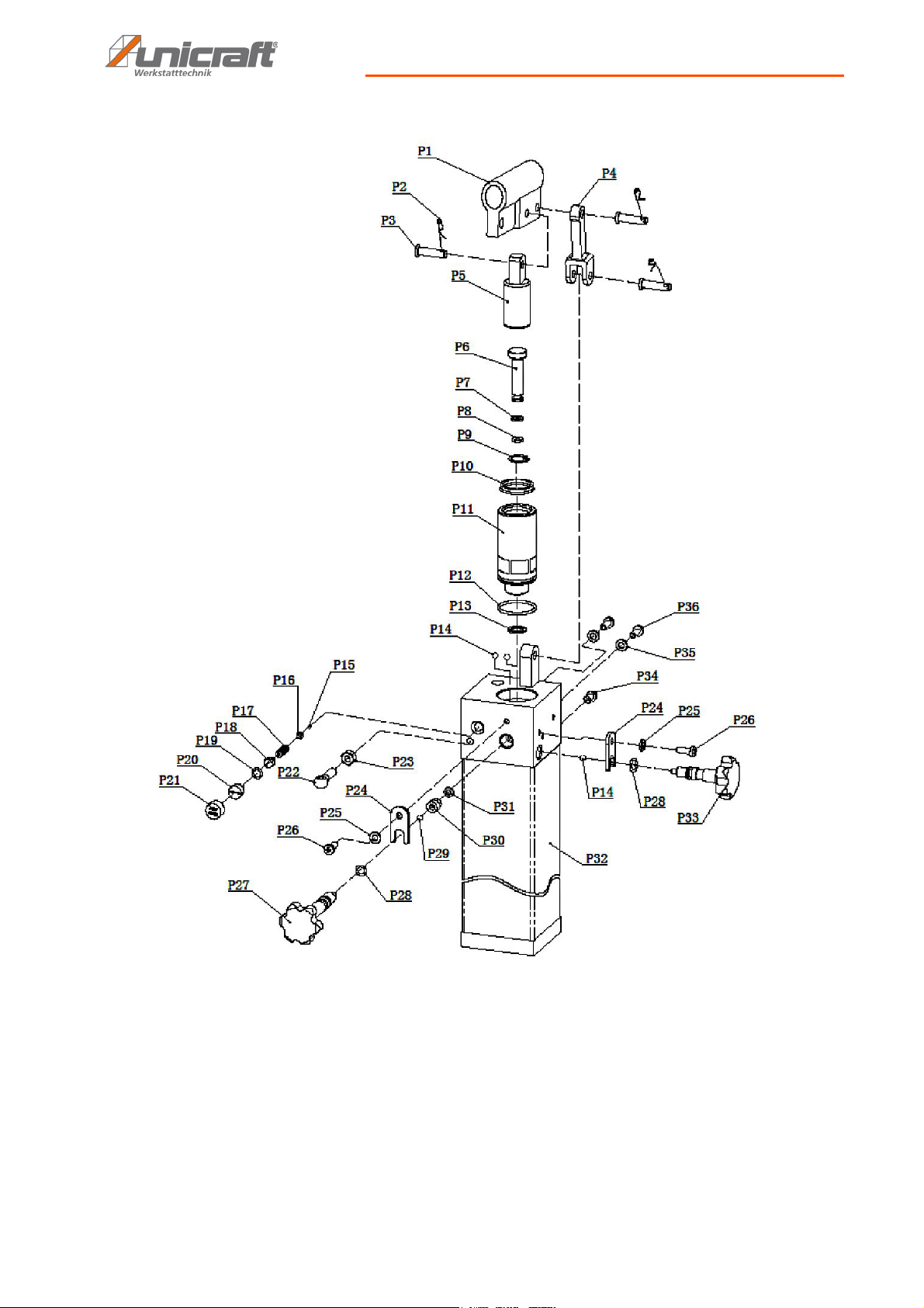
14.2 Spare parts drawings
The following drawings are intended to identify the required spare parts in the event of service. If applicable, submit a
copy of the parts drawing including the highlighted components to your authorised retailer.
Fig. 10: Spare parts drawing 1
16 WPP 15 E | Version 1.02
Page 17
Spare parts
Fig. 11: Spare parts drawing 2
WPP 15 E | Version 1.02 17
Page 18
Spare parts
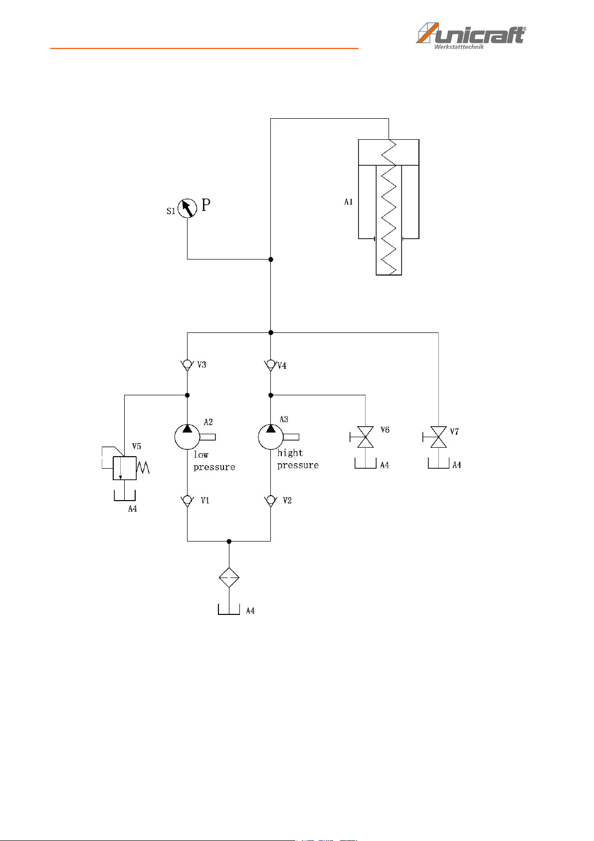
14.3 Hydraulics circuit diagram
Fig. 12: WPP 15 E hydraulics circuit diagram
18 WPP 15 E | Version 1.02
Page 19

15 EU Declaration of Conformity
As per machine directive 2006/42/EC, Annex II 1.A
Manufacturer/seller: Stürmer Maschinen GmbH
Dr.-Robert-Pfleger-Str. 26
D-96103 Hallstadt
Germany
hereby declares that the following product
Product group: Unicraft® workshop technology
Machine type: Hydraulic workshop press
Machine designation: WPP 15 E
Item number: 630 0016
EU Declaration of Conformity
Serial number: ____________
Year of manufacture: 20___
complies with all relevant regulations of the aforementioned directive as well as any other, applicable directives (subsequently added) -including the changes applicable at the time the declaration was made.
Relevant EU directive: 1997/23/EC Directive for pressurised devices (until 18.07.2016)
2014/68/EU Directive for pressurised devices (from 19.07.2016)
The following, harmonised standards have been applied:
DIN EN ISO 12100:2010 Safety of machinery - general design principles -
Risk assessment and reduction of risks
DIN EN 693:2009 Tooling machines - safety - hydraulic presses
DIN EN 1494:2009-05 Mobile or movable hoisting devices and related equipment
Responsible for documentation: Technology department, Dr.-Robert-Pfleger-Str. 26, D-96103 Hallstadt
Hallstadt, 30.04.2015
______________________
Kilian Stürmer
General Manager
WPP 15 E | Version 1.02 19
Page 20

www.unicraft.de
 Loading...