

Unicos URK-700 Service manual

SERVICE MANUAL
AURO REF / KERATOMETER URK-700
Revision 1.01 UNICOS Co., Ltd. www.e-unicos.com
Before use this instrument, be sure to read this manual collectively.

CONTENTS
1. General
1.1 Features ············································································································· 1
1.2 Dimensions ········································································································· 2
2. Operational Description
2.1 Measurement Principle
2.1.1 Refractometry ······································································································ 3
2.1.2 Keratometry ········································································································· 4
2.2 Layout of Optical System ················································································ 6
2.3 Electrical System
2.3.1 Block Diagram ······································································································ 8
2.3.2 Electrical Wiring ································································································ 9
2.3.3 Eyeball Diagram Generated by the REF Measurement ················································· 10
3. Repair Guide
3.1 Disassembly and Adjustments
3.1.1 Disassembling of Covers ·······················································································11
3.1.2 Disassembling of LCD module················································································· 13
3.1.3 Disassembling of Main PCB ···················································································· 13
3.1.4 Disassembling of Optical head assembly ································································ 14
3.1.5 Disassembling of Printer ····················································································· 15
3.1.6 Disassembling of SMPS ·························································································· 16
3.1.7 Disassembling of Headrest ···················································································· 17
3.1.8 Slit and photosensor Space Adjustment ·································································· 18
3.2 Calibration
3.2.1 Refractometry calibration ···················································································· 19
3.2.2 Keratometry calibration ······················································································· 24
4. SERVICE PARTS LIST
4.1 OPTICAL HEAD ASS’Y ························································································· 29
4.2 LOWER BASE ASS’Y ···························································································· 29
ⅰ

4.3 JOYSTICK ASS’Y ································································································ 29
4.4 UPPER BASE ASS’Y ···························································································· 29
4.5 COVER ASS’Y ····································································································· 30
4.6 HEADREST ASS’Y ································································································ 30
4.7 ACCESSORY ASS’Y ······························································································31
1

1. General
1.1 Features
Refracometry
Vertex Distance(VD) 0.0, 10.0, 12.0, 13.5, 15.0 mm
Sphere Power(SPH) -25.00 ~+22.00 D (atthevertexdistanceof 12mm)
(Incrementsselectablebetween0.12and0.25D)
Cylinder Power(CYL) 0.00 ~ ±10.00 D
(Incrementsselectablebetween0.12and0.25D)
Axis(AX) 1 ~ 180˚ (Increments: 1˚)
Cylinder Form -, +, MIX
IOL Switch ○
Pupil Distance(PD) 10 ~ 85 mm
Minimum Pupil Diameter 2.0 mm
Eye fixation target Scene with a red roof house
Keratometry
Radius of curvature (Increment) 5.0 ~ 10.2 mm (Increments: 0.01mm)
Refractive power (Increment) 33.00 ~ 67.50 D (whencorneaequivalentrefractiveindexis1.3375)
(Incrementsselectable from0.05,0.12,0.25)
Astigmatism (Increment) 0.00 ~ -15 D (Incrementsselectable from0.05,0.12,0.25)
Axis (Increment) 1 ~ 180 (Increments: 1)
Cornea equivalent refractive index 1.3375, 1.332, 1.336
Measurement range Ø2.0mm
Contact lens base curve measurement ○
Other Features
PD measurement 10 ~ 85 mm
Corneal size measurement 2.0 ~ 12.0 mm (Increments: 0.1mm)
User key LCD monitor down side
Vertical movement of measurement head By rotation of operation lever
Stage sliding method Sliding lever
Stage lock Stage holding knob
TV camera Basis (Two-dimensional sensor)
Image position and focus adjustment Mechanical
LCD monitor 6.4 inches
Printing method, paper width Thermal, 58 mm
Measurement button Pushbutton switch
Power saving system Select OFF, 3 MIN, 5 MIN and 10 MIN
Clock ○
Stage movement range Right and Left: 903 mm, Back and forth: 503 mm
Measurement Head Vertical movable range 253 mm
Chin Rest Vertical Moving amout 553 mm
1

Dimension 248(W) 476(D) 475(H)mm
Weight Approximately 21 kg
2
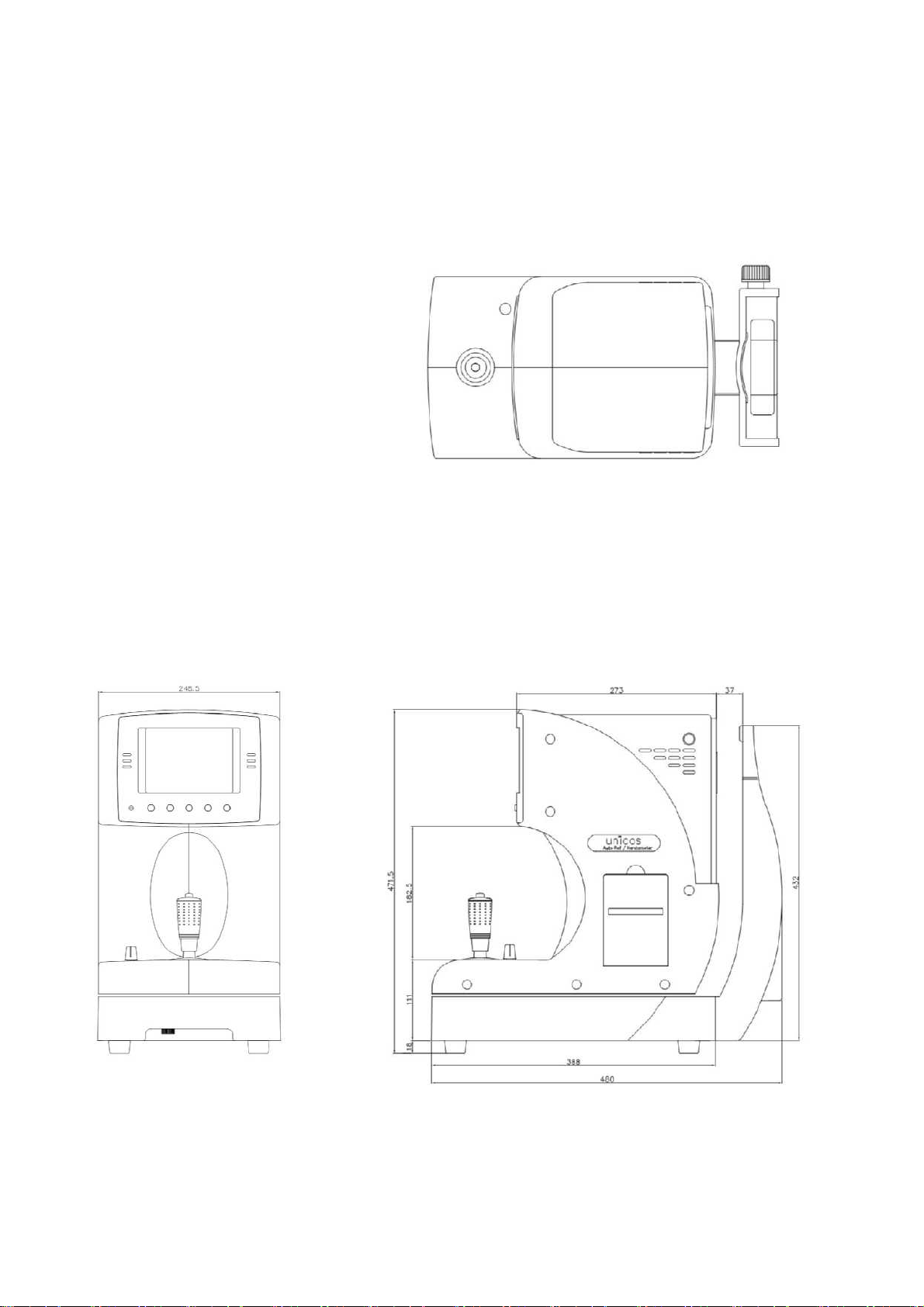
1.2 Dimensions
3
2. Operational Description
2.1 Measurement Principle
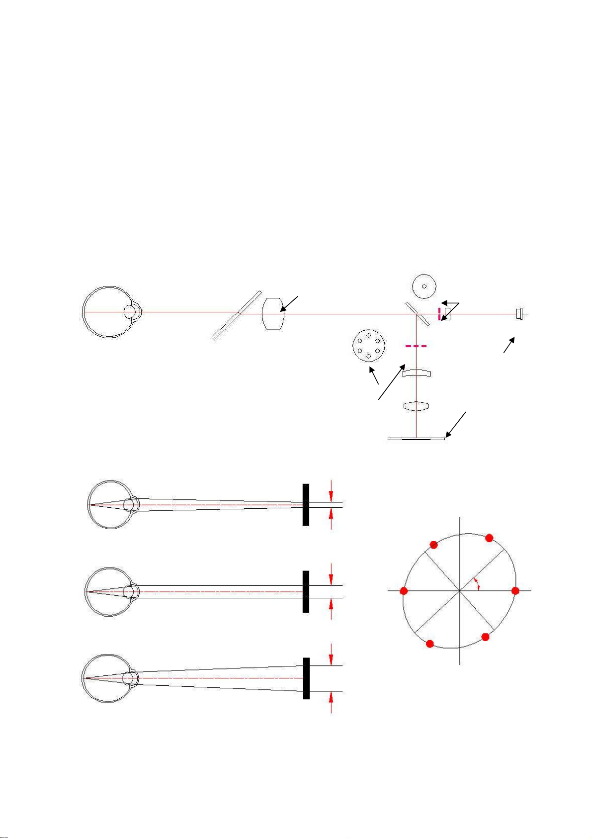
2.1.1 Refractometry
(1) A ray of light from the light source is reflected in the retina of examinee.
(2) According to refraction of examinee’s eye, the reflected light in the examinee’s eye exits as follow.
1) In case of emmetropia, the ray of light is parallel.
2) In case of near-sightedness, the ray of light is convergence.
3) In case of a farsighted eye, the ray of light is divergence.
(3) Then, the ray of light through the optical system imaged in the camera as six spot.
(4) Calculate the distance of coordinate of six spots and the center, obtain SPH, CYL and AX value.
Objective Lens
Aperture
Light source
Myopia
Emmetropia
Division pattern
For measurement
CCD Camera
-D
Short axis
α
0D
Long axis
Hyperopia
+D
4

2.1.2 Keratometry
Observational Lens
Aperture for m
easuring
Mire Light Source
CCD Camera
Objective Lens for Keratoscope
Mire Light is reflected examinee’s cornea, is imaged on the camera after through the Optical System.
Circular Mire Light is reflected circular or ellipse form by Radius of curvature and Astigmia of Examinee
cornea, coordinates of refracted light (XY Coordinates) on the camera is inputted the MPU, calculate that
data and obtain the Radius of Circle or the major axis and the minor axis of ellipse, Angle of Rotation .
Y
Y
The major axis
The minor axis
The minor axis
The major axis
θ
θ
2b2a
2b2a
2
2
X
X
2
2
a
a
θ/2
θ/2
Optical Axis
Optical Axis
X
X
θ/2 h
θ/2 h
R
2
2
Y
Y
+
+
= R
= R
2
2
b
b
R
θ
θ
θ/2
θ/2
R, θ and h are correlated Snell’s Low as follows (R is radius of curvature of cornea, θ is incident angle
of Mire Light in the cornea, h is distance between position of Mire Light image at the cornea and Optical
Axis), obtain the long or short radius of curvature of cornea by this formula.
R =
h
sin(θ/2)
5

R, D and n are correlated as follows (R is radius of curvature of cornea, D is refractive power of the cornea,
1)
equivalent refractive index
=
1.3375
,
,
n is refractive index of the cornea), obtain the diopter(D) of cornea by R, long or short radius of curvature
of the cornea..
D =
6
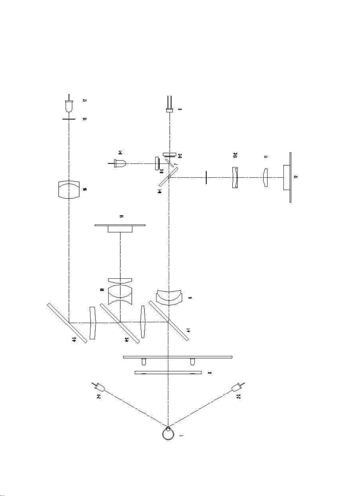
2.2 Layout of Optical System
7

Layout of Optical System
1: Examinee’s Eye
2-1, 2-2: External Led
3: Mire Ring Unit for Keratometry
4-1: Half Mirror
4-2: Half Mirror
4-3: Total Reflection Mirror
5: Objective Lens
6-1: Aperture Mirror
6-2: Aperture
7: Half Mirror
8-1: Aiming Light Source
8-2: Aiming Pattern
9: Light Source for Refractometry
10-1: Division Pattern
10-2: Prism Lens
11: Relay Lens
12: Camera for Refractometry
13: Coneal Relay Lens
14: Camera for Keratometry
15: Refractive Poser Revision Lens
16: Internal Chart
17: Internal Chart Illuminator
Route of Optical System
External illumination system: 2-1 2-1 1
System for the fogging method system: 1716 15 4-34-24-11
Keratometry system: 3 14-14-2 1314
Refractometry system: 9 7 6-2 6-154-114-1 5 6-1 10-1 10-211 12
Automatic measurement system: 3 1
8
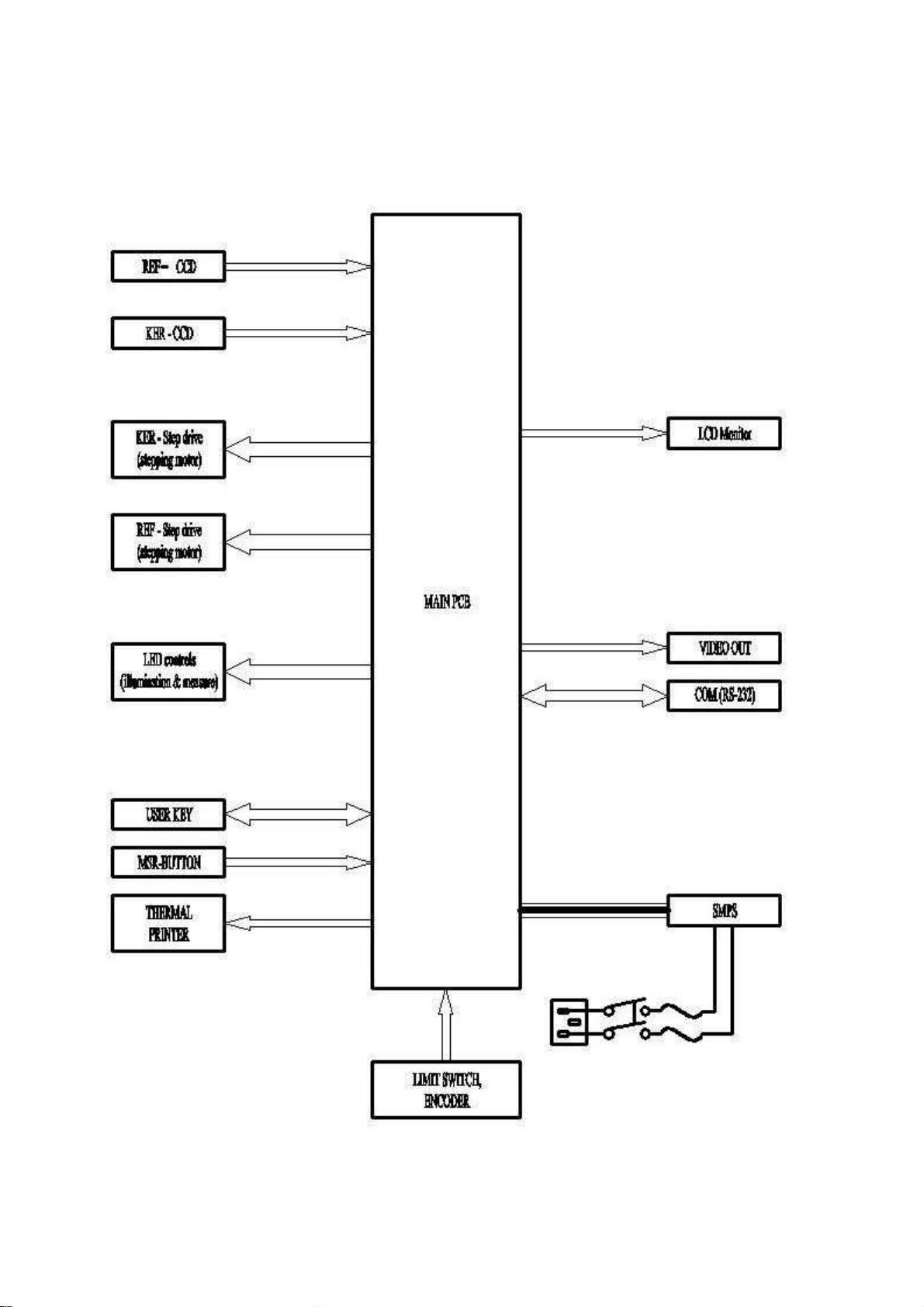
2.3 Electrical System
2.3.1 Block Diagram
9

2.3.2 Electrical Wiring
10

2.3.3 Eyeball Diagram Generated by the REF Measurement
It is possible to print the refrection state diagram regarding the result of the REF measurement to the
internal printer. This function will be performed when ‘PRINT=ALL’ in the Page 2/5 of the SETUP MODE.
See the following table and diagram for further information.
Classification of Data NOT NEA FAR AS
Emmetropia -0.5 S +0.5 -0.5 C 0.0 ◎
Myopia S < -0.5 -0.5 C 0.0 ◎
Simple Myopic
-0.5S 0.0 C < -0.5 ◎ ◎
Astigmatism
Compound
Myopic
S < -0.5 C < -0.5 ◎ ◎
Astigmatism
Mixed
0.0 < S C < -0.5 S+C < 0.0 ◎
Astigmatism
Hyperopia +0.5 < S -0.5 C 0.0 0.0 < S+C ◎
Simple Hyperopic
+0.5 < S C < -0.5
Astigmatism
0.0 S+C
◎ ◎
+0.5
Compound
Hyper-
opic
+0.5 < S+C ◎ ◎
Astigmastism
Table Eyeball Output by REF Measurement
Emmetropia / Normal Mixed Astigmatism
Myopia / Near Sightedness Hyperopia / Far Sightedness
Simple Myopic Astigmatism Simple Hyperopic Astigmatism
11

Compound Myopic Astigmatism Compound Hyperopic Astigmatism
Figure Diagram of the eye ball output by REF Measurement
12

3. Repair Guide
3.1 Disassembly and Adjustments
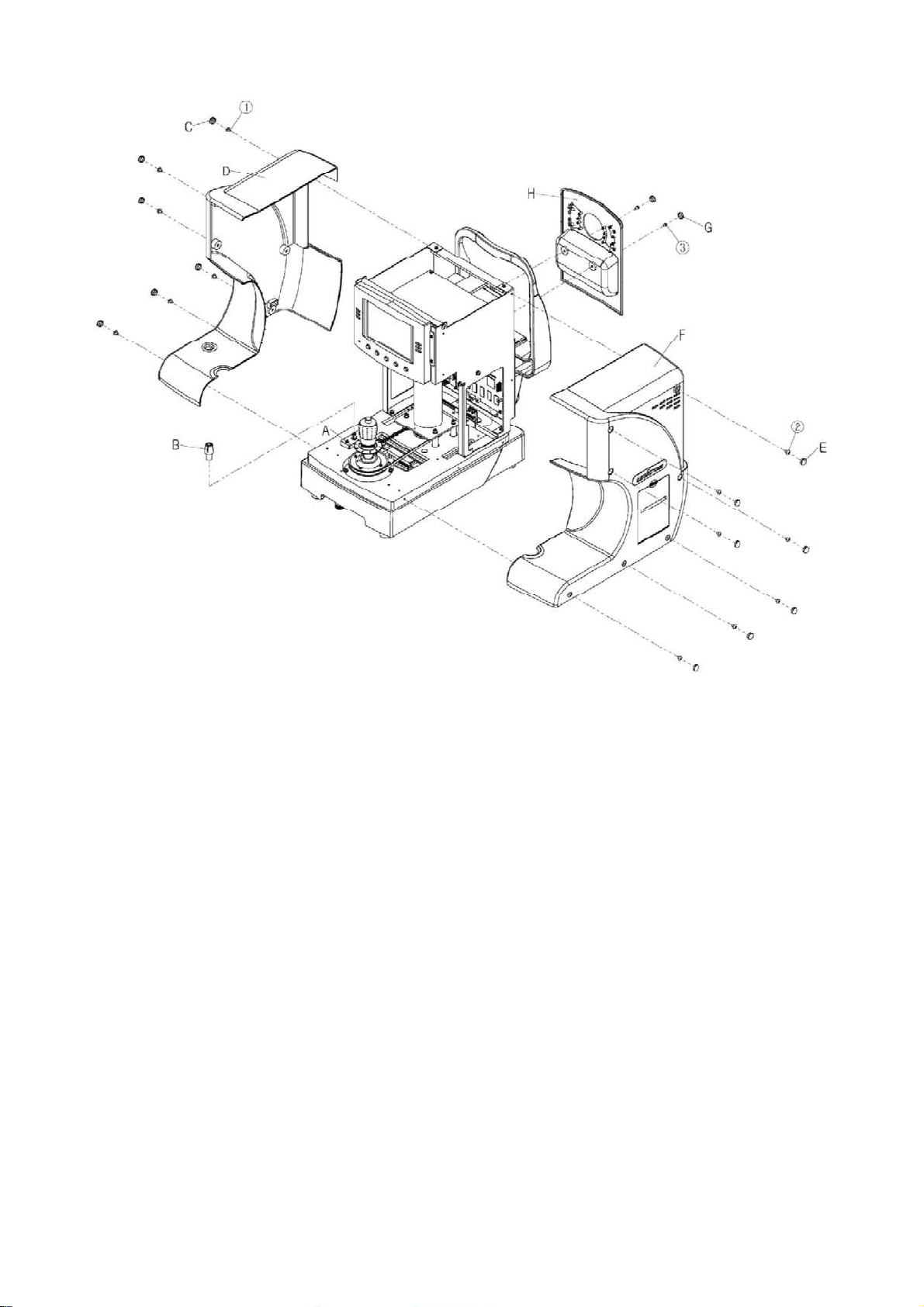
3.1.1 Disassembling of Covers
3.1.1.1 Joystick decoration (A)
1) Remove the Joystick decoration
3.1.1.2 Stage holding knob (B)
1) Remove the Stage holding knob
3.1.1.3 Main cover-L (D)
1) Remove the seven caps (C) and seven screws ①
3.1.1.4 Main cover-R (F)
1) Remove the seven caps (E) and seven screws ②
2) Remove the head left cover claw as pushing down the cover (2 point)
3) Remove the Printer cable connector
3.1.1.5 Rear cover (H)
1) Remove the two caps (G) and two screws ③
2) Remove the external led connector
11
12

3.1.2 Disassembling of LCD module
3.1.2.1 LCD module (A)
1) Remove the connectors
2) Remove the fourscrews ① and then remove the LCD module
3.1.2.2 LCD monitor (B)
1) Remove the three screws ③
2) Remove the fourscrews ④ & LCD Bracket ⑤
3.1.2.3 Remove the LCD window (D)
3.1.2.4 User key module (E)
1) Remove the four screws ⑥
13

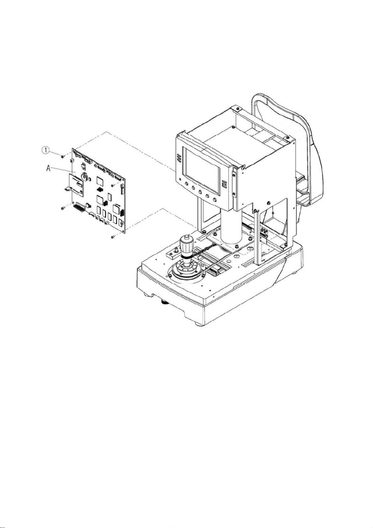
3.1.3 Disassembling of main PCB (A)
1) Remove the connectors
2) Remove the fourscrews ① and then remove the main PCB
14
15
 Loading...