

Page 1
ENDAT-4601 USERS MANUAL
UNICORN COMPUT ER CORP.
ENDAT-4601
User’s Manual
For ENDAT-4601 PCB ver. A3 or later
Jun.25.2014
Document version: Preliminary edition
1
Page 2

ENDAT-4601 USERS MANUAL
UNICORN COMPUTER CORP.
Copyright Notice
The content of this manual has been checked for accuracy. The manufacturer
assumes no responsibility for any inaccuracies that may be contained in this
manual. The manufacturer reserves the right to make improvements or
modification to this document and/or the product at any time without prior
notice. No part of this document may be reproduced, transmitted, photocopied or
translated into any language, in any form or by any means, electronic, mechanical,
magnetic, optical or chemical, without the prior written permission of the
manufacturer.
AMD is registered trademark of AMD T echnology Incorporation
GEODE LX is registered trademark of AMD Technology Incorporation
Realtek is registered trademark of Realtek Technologies Inc.
Multiscan is a trademark of Sony Corp of America
IBM, EGA, VGA, PC/XT, PC/AT, OS/2 and PS/2 are registered trademarks of
International Business Machines Corporation
Intel® is a registered trademark of Intel Corporation
VIA is registered trademark of VIA Technology Incorporation
Plug and Play is registered trademarks of Intel Corporation
Microsoft, Windows and MS-DO S ar e trademarks of Microsoft Corporation
Award is a trademark of Phoenix Software Inc.
PCI is a registered trademark of PCI Special Interest Group
Other product names mentioned herein are used for identification purpose only and
may be trademarks and/or registered trademarks of their respective companies.
Installation Notice
The manufacturer recommends using a grounded plug to ensure proper
motherboard operation. Care should be used in proper conjunction with a
grounded power recept acle to avoid possible electrical shock. All in tegrated circuits
on this motherboard are sensitive to static electricity. To avoid damaging
components from electrost atic discharge , please do not remove the board from the
anti-static pac king before di scharging any static electricity to your body, by wearing
a wrist-grounding strap. The manufacturer is not responsible for any damage to the
motherboard due to improper operation.
2
Page 3
ENDAT-4601 USERS MANUAL
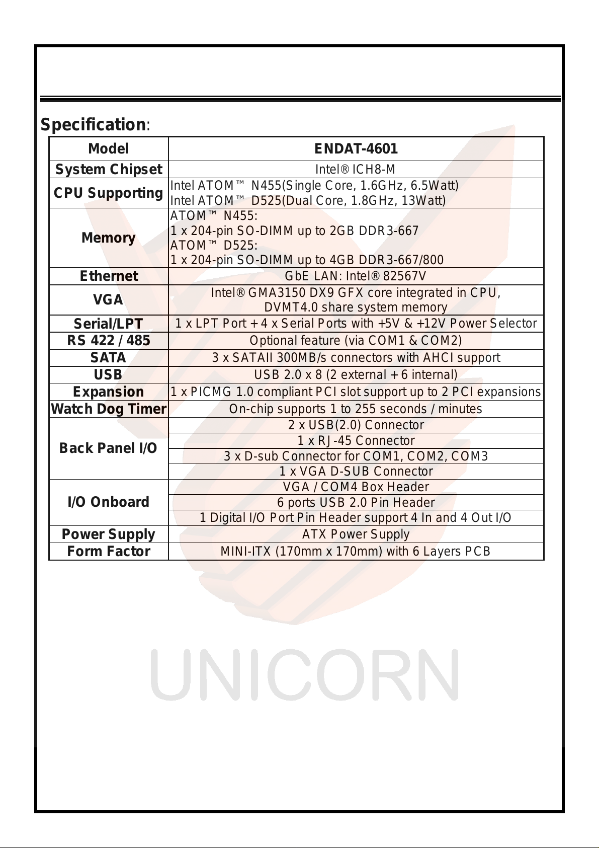
Specification:
Model ENDAT-4601
UNICORN COMPUT ER CORP.
System Chipset
CPU Supporting
Memory
Ethernet
VGA
Serial/LPT
RS 422 / 485
SATA
USB
Expansion
Watch Dog Timer
Back Panel I/O
I/O Onboard
Power Supply
Form Factor
Intel® ICH8-M
Intel ATOM™ N455(Single Core, 1.6GHz, 6. 5Watt)
Intel ATOM™ D525(Dual Core, 1.8GHz, 13Watt)
ATOM™ N455:
1 x 204-pin SO-DIMM up to 2GB DDR3-667
ATOM™ D525:
1 x 204-pin SO-DIMM up to 4GB DDR3-667/800
GbE LAN: Intel® 82567V
Intel® GMA3150 DX9 GFX core integrated in CPU,
DVMT4.0 share system memory
1 x LPT Port + 4 x Serial Ports with +5V & +12V Power Selector
Optional feature (via COM1 & COM2)
3 x SATAII 300MB/s connectors with AHCI support
USB 2.0 x 8 (2 external + 6 internal)
1 x PICMG 1.0 compliant PCI slot support up to 2 PCI expansions
On-chip supports 1 to 255 seconds / minutes
2 x USB(2.0) Connector
1 x RJ-45 Connector
3 x D-sub Connector for COM1, COM2, COM3
1 x VGA D-SUB Connector
VGA / COM4 Box Header
6 ports USB 2.0 Pin Header
1 Digital I/O Port Pin Header support 4 In and 4 Out I/O
ATX Power Supply
MINI-ITX (170mm x 170mm) with 6 Layers PCB
3
Page 4
ENDAT-4601 USERS MANUAL
UNICORN COMPUTER CORP.
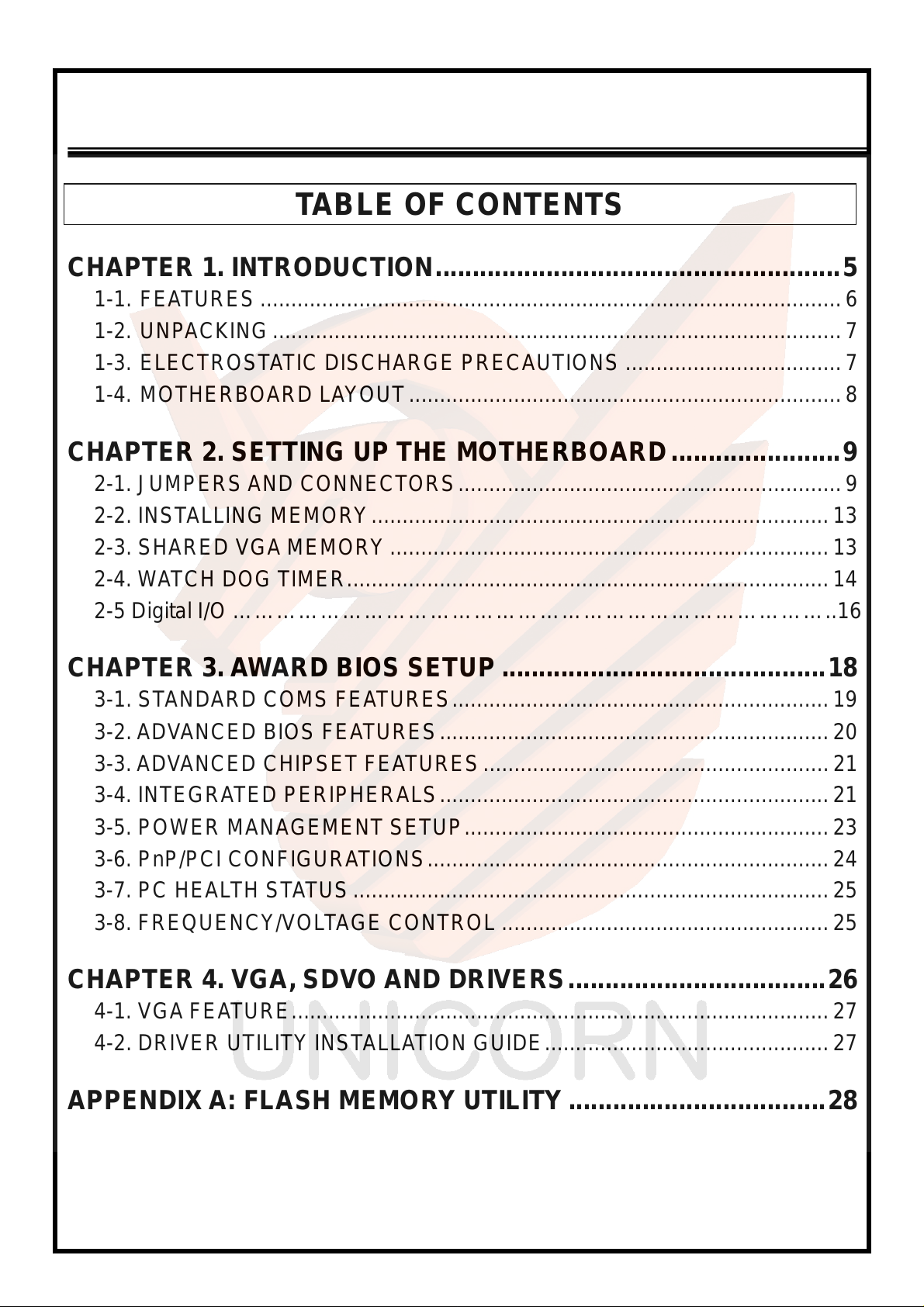
TABLE OF CONTENTS
CHAPTER 1. INTRODUCTION .......................................................5
1-1. FEATURES..............................................................................................6
1-2. UNPACKING............................................................................................ 7
1-3. ELECTROSTATIC DISCHARGE PRECAUTIONS ...................................7
1-4. MOTHERBOARD LAYOUT ...................................................................... 8
CHAPTER 2. SETTING UP THE MOTHERBOARD.......................9
2-1. JUMPERS AND CONNECTORS..............................................................9
2-2. INSTALLING MEMORY..........................................................................13
2-3. SHARED VGA MEMORY.......................................................................13
2-4. WATCH DOG TIMER..............................................................................14
2-5 Digital I/O ………………………………………………………………………..16
CHAPTER 3. AWARD BIOS SETUP............................................18
3-1. STANDARD COMS FEAT URES............................................................. 19
3-2. ADV ANCED BIOS FEA TURES............................................................... 20
3-3. ADV ANCED CHIPSET FEA TURES................ ........................................ 21
3-4. INTEGRATED PERIPHERALS............................................................... 21
3-5. POWER MANAGEMENT SETUP........................................................... 23
3-6. PnP/PCI CONFIGURATIONS.................................................................24
3-7. PC HEALTH STATUS.............................................................................25
3-8. FREQUENCY/VOLTAGE CONTROL .....................................................25
CHAPTER 4. VGA, SDVO AND DRIVERS...................................26
4-1. VGA FEATURE.......................................................................................27
4-2. DRIVER UTILITY INSTALLATION GUIDE..............................................27
APPENDIX A: FLASH MEMORY UTILITY...................................28
APPENDIX B: LIMITED WARRANTY............................................... 29
4
Page 5
ENDAT-4601 USERS MANUAL
UNICORN COMPUT ER CORP.
Chapter 1. Introduction
In order to cope with the challenges o f the system performance issues and demand
of much more visually embed d ed system in diverse application, ENDAT-4601
system board provides the ultimate solution with Intel® ATOM N455 / D525
Processors (667/800 MHz FSB). This package offers a high performance Intel®
CPU with optimal power efficiency on the embedded market.
ENDAT-4601 supports
capacity is up to 2GB (N455) or 4GB (D525).
ENDAT-4601 integrated Mobile Intel® Graphics Media Accelerator 3150
(GMA3150) which supp orts Microsoft DirectX 9 and MPEG-2 decoder for higher
visual application.
ENDAT-4601 provides one PCI slot to support one standard PCI interface.
single channel DDR3 667/800 MHz memory. The maximal
The ideal solutions of ENDAT-4601
- POS system
- KIOSK
- Vehicle system
- Interactive system
- Industrial controller
- Gaming system
- Medical system
- Embedded system equipment
5
Page 6
ENDAT-4601 USERS MANUAL
UNICORN COMPUTER CORP.
1-1. Features
Basic Feature:
Intel® Atom™ N455 / D525 processor.
Single channel DDR3 SO-DIMM socket supports 667/800 MHz up
to 4 GB.
One PCI Express interface Gigabit Ethernet chip on-board.
Intel® Graphics Media Accelerator 3150 (GMA3150).
PCI slot support.
Four fully functional serial ports.
Support ATX power supply.
Software Support
Drivers for major embedded operating systems: Linux, Windows7,
Windows XP, Windows XP embedded.
Ordering information:
Standard edition:
ENDA T-4601-N4: Atom™ N455
ENDA T-4601-D5: Atom™ D525
6
Page 7
ENDAT-4601 USERS MANUAL
UNICORN COMPUT ER CORP.
1-2. Unpacking
The motherboard comes securely packaged in a sturdy cardboard shipping carton. In
addition to the User's Manual, t h e motherboard package includes the following items:
ENDAT-4601 System Board
One SATA HDD Cable
LCD cable
CD with Driver utilities for on-board chipsets, VGA and LAN adapter
If any of these items is missing or damage, please contact the dealer whom you purchas e
the motherboard from. Save the shipping material and carton in the event that you want to
ship or store the board in the future.
(Optional)
Note:
Leave the motherboard in its original package until you are ready to install it!
1-3. Electrostatic Discharge Precautions
Make sure you properly ground yourself before handling the motherboard, or other system
components. Electrostatic discharge can easily damage the components. Note: You must
take special precaution when handling the motherboard in dry or air-conditioned
environments.
7
Page 8
ENDAT-4601 USERS MANUAL
UNICORN COMPUTER CORP.
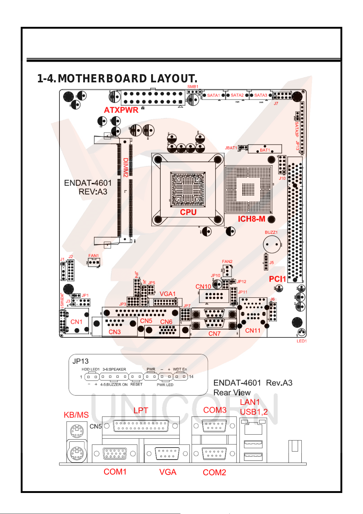
1-4. MOTHERBOARD LAYOUT.
8
Page 9
ENDAT-4601 USERS MANUAL
UNICORN COMPUT ER CORP.
Chapter 2. Setting up the Motherboard
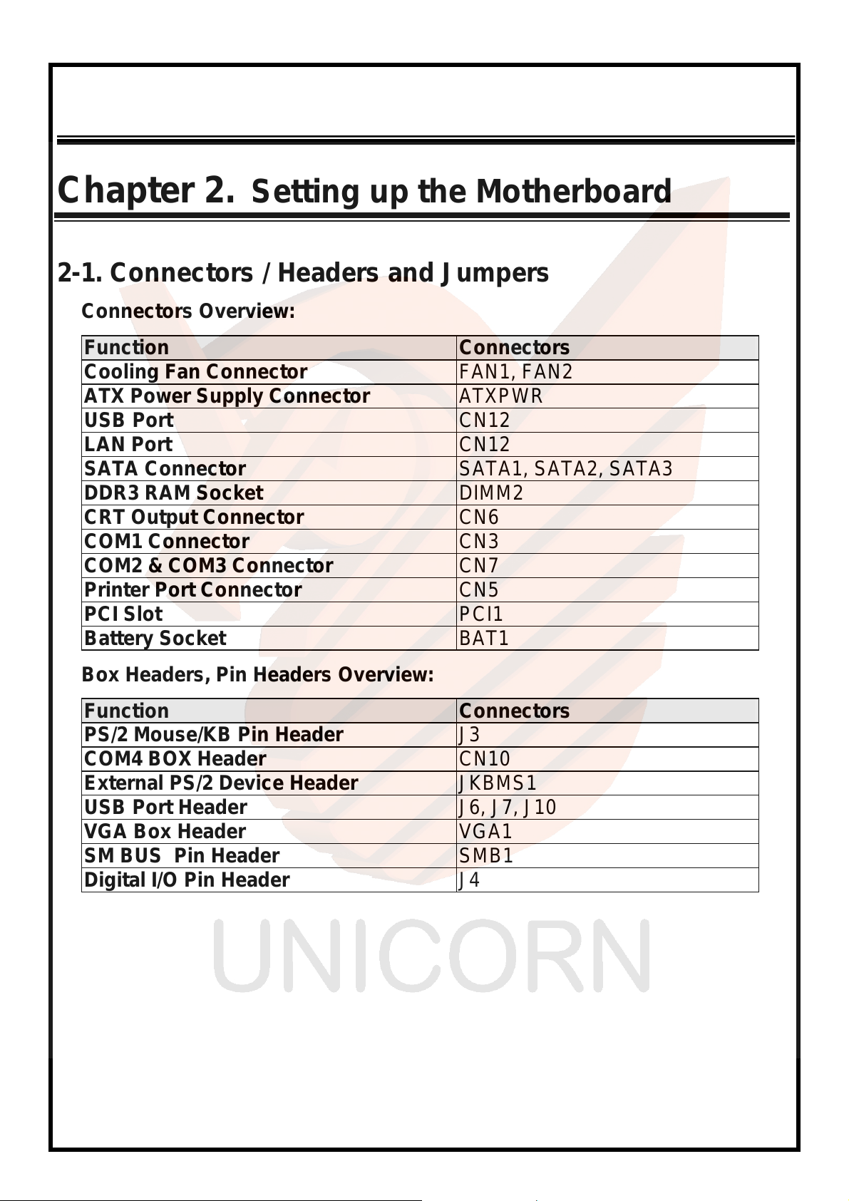
2-1. Connectors / Headers and Jumpers
Connectors Overview:
Function Connectors
Cooling Fan Connector FAN1, FAN2
ATX Power Supply Connector ATXPWR
USB Port CN12
LAN Port CN12
SATA Connector SATA1, SATA2, SATA3
DDR3 RAM Socket DIMM2
CRT Output Connector CN6
COM1 Connector CN3
COM2 & COM3 Connector CN7
Printer Port Connector CN5
PCI Slot PCI1
Battery Socket BAT1
Box Headers, Pin Headers Overview:
Function Connectors
PS/2 Mouse/KB Pin Header J3
COM4 BOX Header CN10
External PS/2 Device Header JKBMS1
USB Port Header J6, J7, J10
VGA Box Header VGA1
SM BUS Pin Header SMB1
Digital I/O Pin Header J4
9
Page 10
ENDAT-4601 USERS MANUAL
UNICORN COMPUTER CORP.
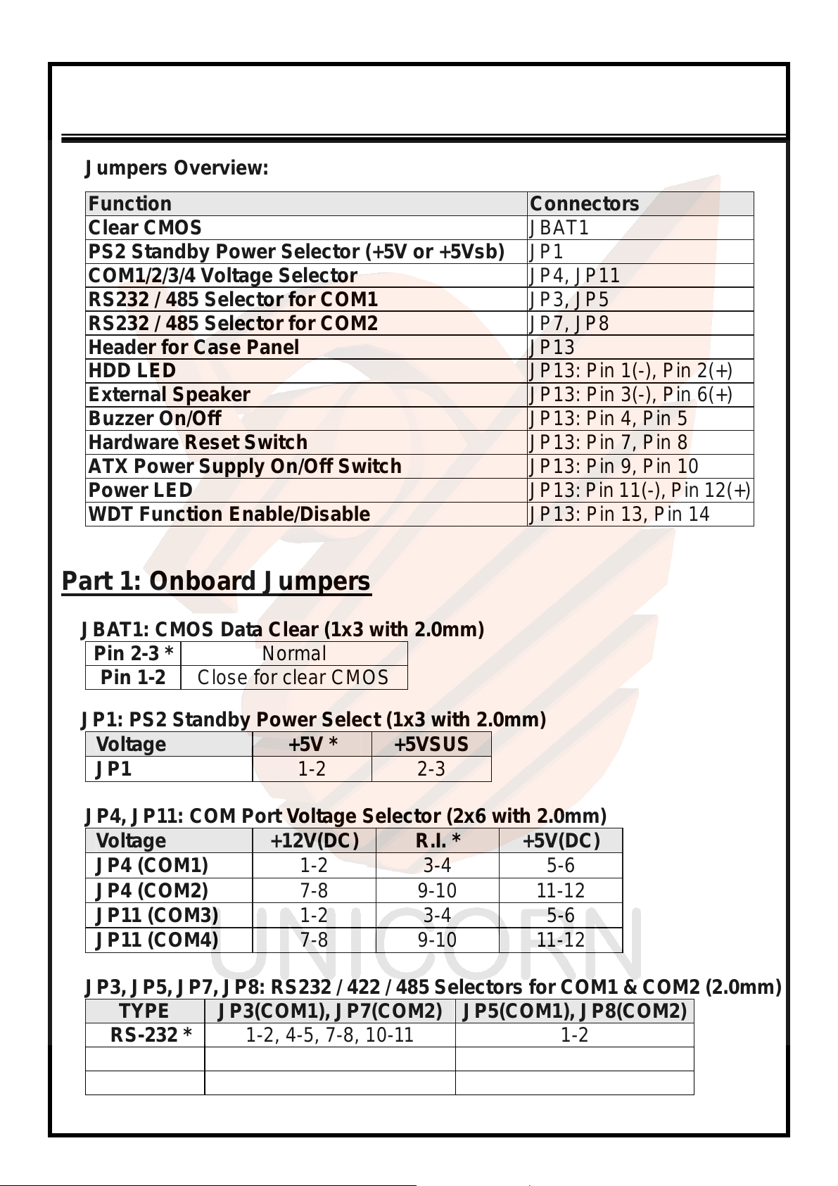
Jumpers Overview:
Function Connectors
Clear CMOS JBAT1
PS2 Standby Power Selector (+5V or +5Vsb) JP1
COM1/2/3/4 Voltage Selector JP4, JP11
RS232 / 485 Selector for COM1 JP3, JP5
RS232 / 485 Selector for COM2 JP7, JP8
Header for Case Panel JP13
HDD LED JP13: Pin 1(-), Pin 2(+)
External Speaker JP13: Pin 3(-), Pin 6(+)
Buzzer On/Off JP13: Pin 4, Pin 5
Hardware Reset Switch JP13: Pin 7, Pin 8
ATX Power Supply On/Off Switch JP13: Pin 9, Pin 10
Power LED JP13: Pin 11(-), Pin 12(+)
WDT Function Enable/Disable JP13: Pin 13, Pin 14
Part 1: Onboard Jumpers
JBAT1: CMOS Data Clear (1x3 with 2.0mm)
Pin 2-3 * Normal
Pin 1-2 Close for clear CMOS
JP1: PS2 Standby Power Select (1x3 with 2.0mm)
Voltage +5V * +5VSUS
JP1 1-2 2-3
JP4, JP11: COM Port Voltage Selector (2x6 with 2.0mm)
Voltage +12V(DC) R.I. * +5V(DC)
JP4 (COM1) 1-2 3-4 5-6
JP4 (COM2) 7-8 9-10 11-12
JP11 (COM3) 1-2 3-4 5-6
JP11 (COM4) 7-8 9-10 11-12
JP3, JP5, JP7, JP8: RS232 / 422 / 485 Selectors for COM1 & COM2 (2.0mm)
TYPE JP3(COM1), JP7(COM2) JP5(COM1), JP8(COM2)
RS-232 * 1-2, 4-5, 7-8, 10-11 1-2
RS-422 2-3, 5-6, 8-9, 11-12 3-4
RS-485 2-3, 5-6, 8-9, 11-12 5-6
10
Page 11
ENDAT-4601 USERS MANUAL
UNICORN COMPUT ER CORP.
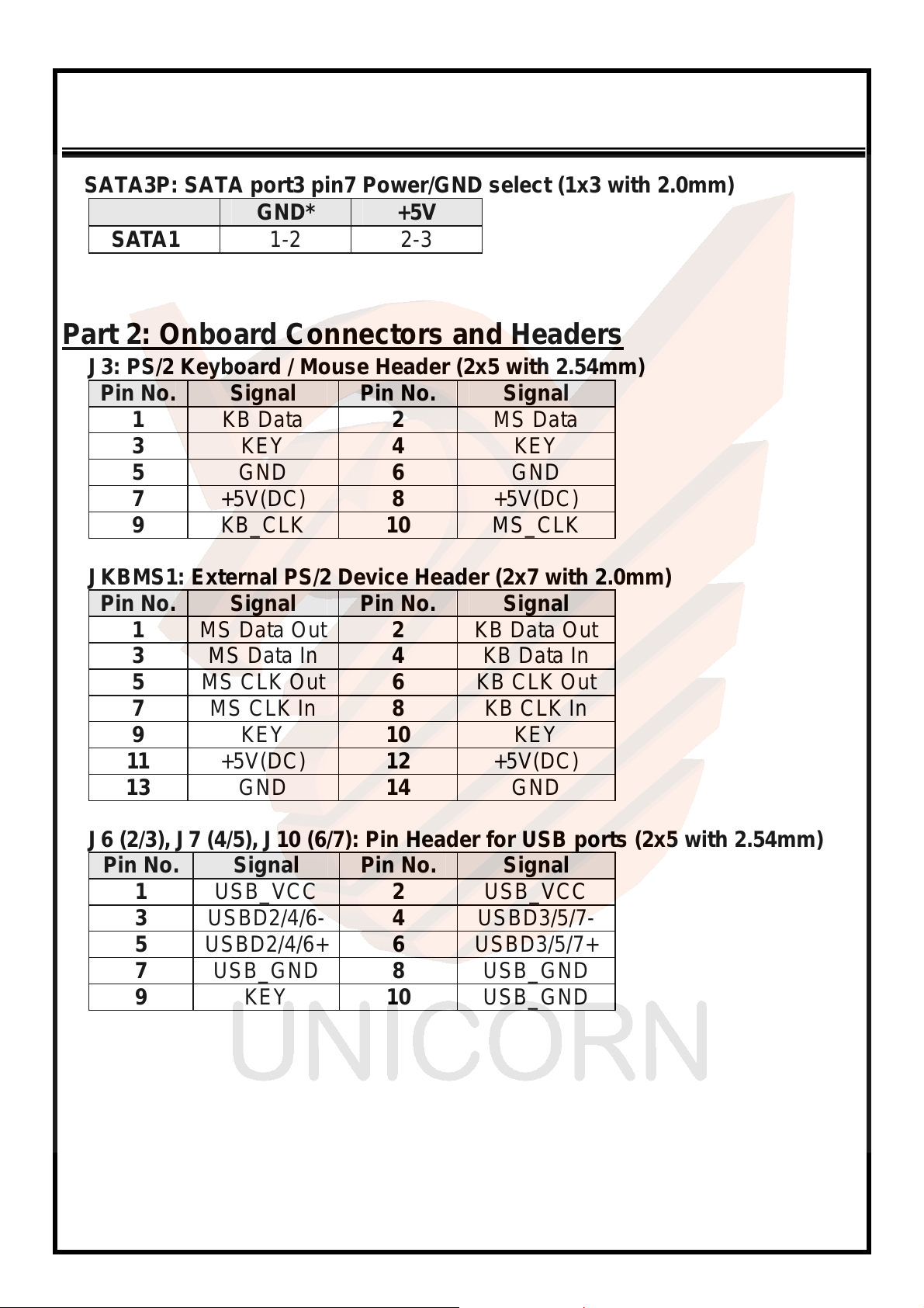
SATA3P: SATA port3 pin7 Power/GND select (1x3 with 2.0mm)
GND* +5V
SATA1 1-2 2-3
Part 2: Onboard Connectors and Headers
J3: PS/2 Keyboard / Mouse Header (2x5 with 2.54mm)
Pin No. Signal Pin No. Signal
1 KB Data 2 MS Data
3 KEY 4 KEY
5 GND 6 GND
7 +5V(DC) 8 +5V(DC)
9 KB_CLK 10 MS_CLK
JKBMS1: External PS/2 Device Header (2x7 with 2.0mm)
Pin No. Signal Pin No. Signal
1 MS Data Out 2 KB Data Out
3 MS Data In 4 KB Data In
5 MS CLK Out 6 KB CLK Out
7 MS CLK In 8 KB CLK In
9 KEY 10 KEY
11 +5V(DC) 12 +5V(DC)
13 GND 14 GND
J6 (2/3), J7 (4/5), J10 (6/7): Pin Header for USB ports (2x5 with 2.54mm)
Pin No. Signal Pin No. Signal
1 USB_VCC 2 USB_VCC
3 USBD2/4/6- 4 USBD3/5/7-
5 USBD2/4/6+ 6 USBD3/5/7+
7 USB_GND 8 USB_GND
9 KEY 10 USB_GND
11
Page 12
ENDAT-4601 USERS MANUAL
UNICORN COMPUTER CORP.
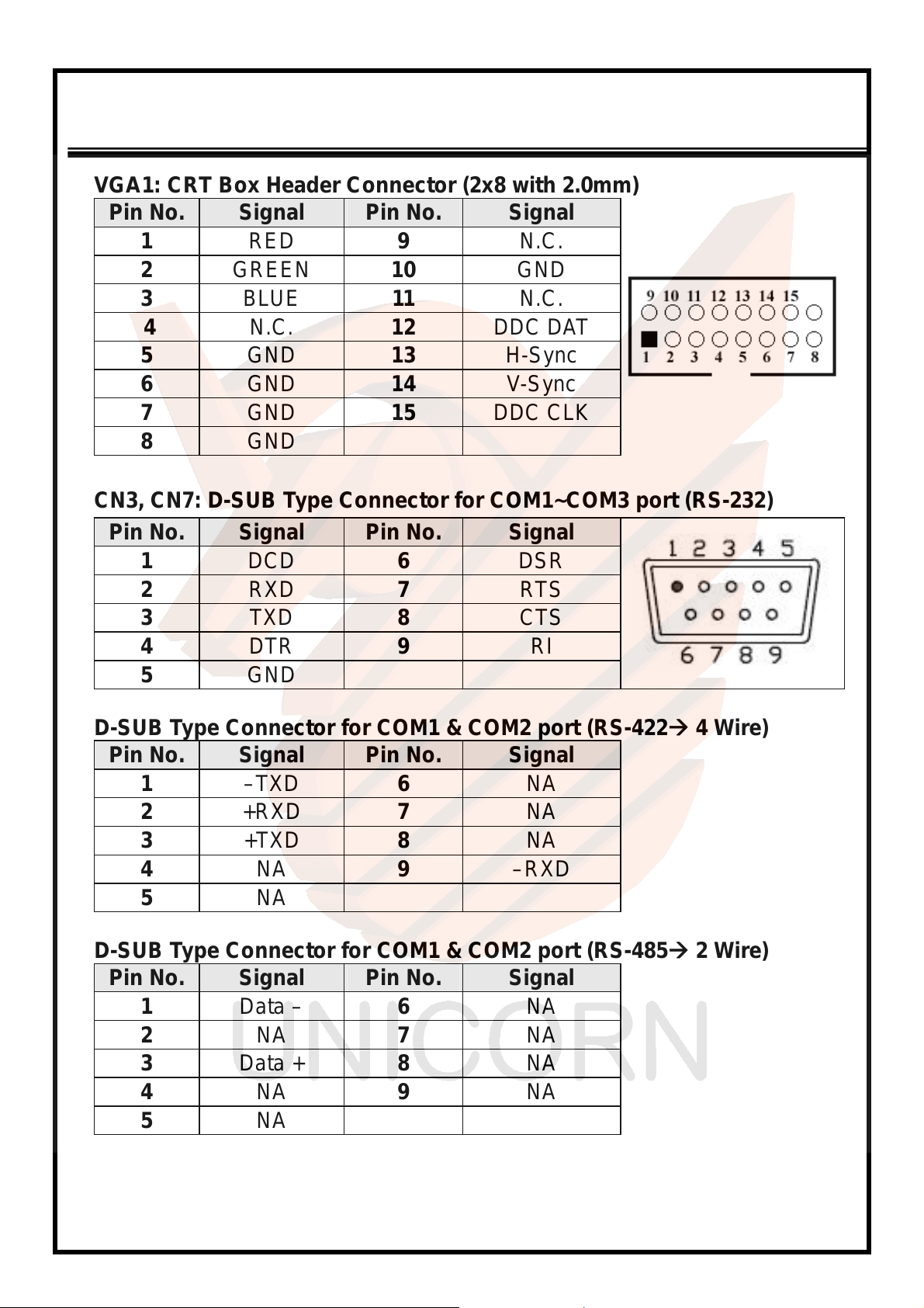
VGA1: CRT Box Header Connector (2x8 with 2.0mm)
Pin No. Signal Pin No. Signal
1 RED 9 N.C.
2 GREEN 10 GND
3 BLUE 11 N.C.
4 N.C. 12 DDC DAT
5 GND 13 H-Sync
6 GND 14 V-Sync
7 GND 15 DDC CLK
8 GND
CN3, CN7: D-SUB Type Connector for COM1~COM3 port (RS-232)
Pin No. Signal Pin No. Signal
1 DCD 6 DSR
2 RXD 7 RTS
3 TXD 8 CTS
4 DTR 9 RI
5 GND
D-SUB Type Connector for COM1 & COM2 port (RS-422 4 Wire)
Pin No. Signal Pin No. Signal
1 –TXD 6 NA
2 +RXD 7 NA
3 +TXD 8 NA
4 NA 9 –RXD
5 NA
D-SUB Type Connector for COM1 & COM2 port (RS-485 2 Wire)
Pin No. Signal Pin No. Signal
1 Data – 6 NA
2 NA 7 NA
3 Data + 8 NA
4 NA 9 NA
5 NA
12
Page 13
ENDAT-4601 USERS MANUAL
UNICORN COMPUT ER CORP.
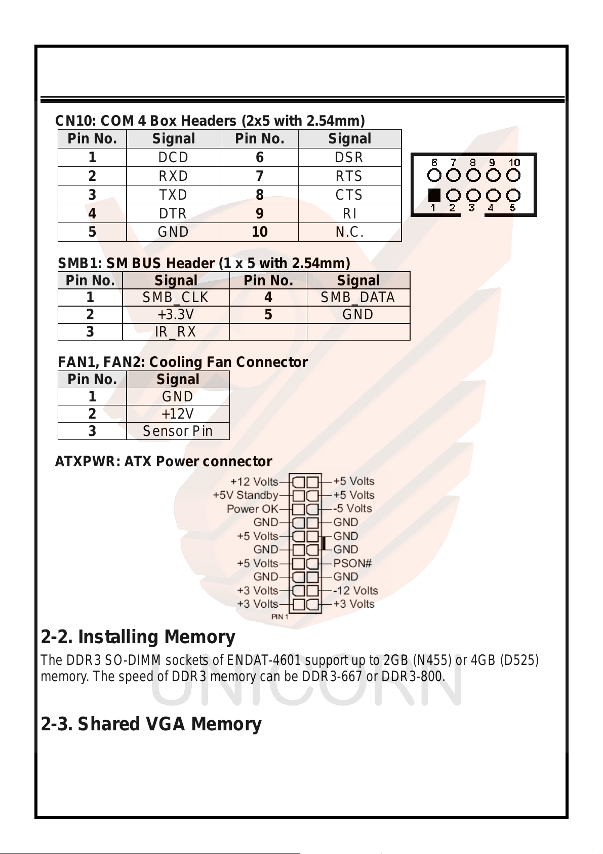
CN10: COM 4 Box Headers (2x5 with 2.54mm)
Pin No. Signal Pin No. Signal
1 DCD 6 DSR
2 RXD 7 RTS
3 TXD 8 CTS
4 DTR 9 RI
5 GND 10 N.C.
SMB1: SM BUS Header (1 x 5 with 2.54mm)
Pin No. Signal Pin No. Signal
1 SMB_CLK 4 SMB_DATA
2 +3.3V 5 GND
3 IR_RX
FAN1, FAN2: Cooling Fan Connector
Pin No. Signal
1 GND
2 +12V
3 Sensor Pin
A TXPWR: ATX Power connector
2-2. Installing Memory
The DDR3 SO-DIMM sockets of ENDAT-4601 support up to 2GB (N455) or 4GB (D525)
memory. The speed of DDR3 memory can be DDR3-667 or DDR3-800.
2-3. Shared VGA Memory
The ENDAT-4601 built-in
system memory. The amount of video memory on motherboard determines the number of
colors and the video graphic resolution.
Intel® GMA3150
graphic engine with DVMT 4.0 up to 384MB of
13
Page 14

ENDAT-4601 USERS MANUAL
UNICORN COMPUTER CORP.
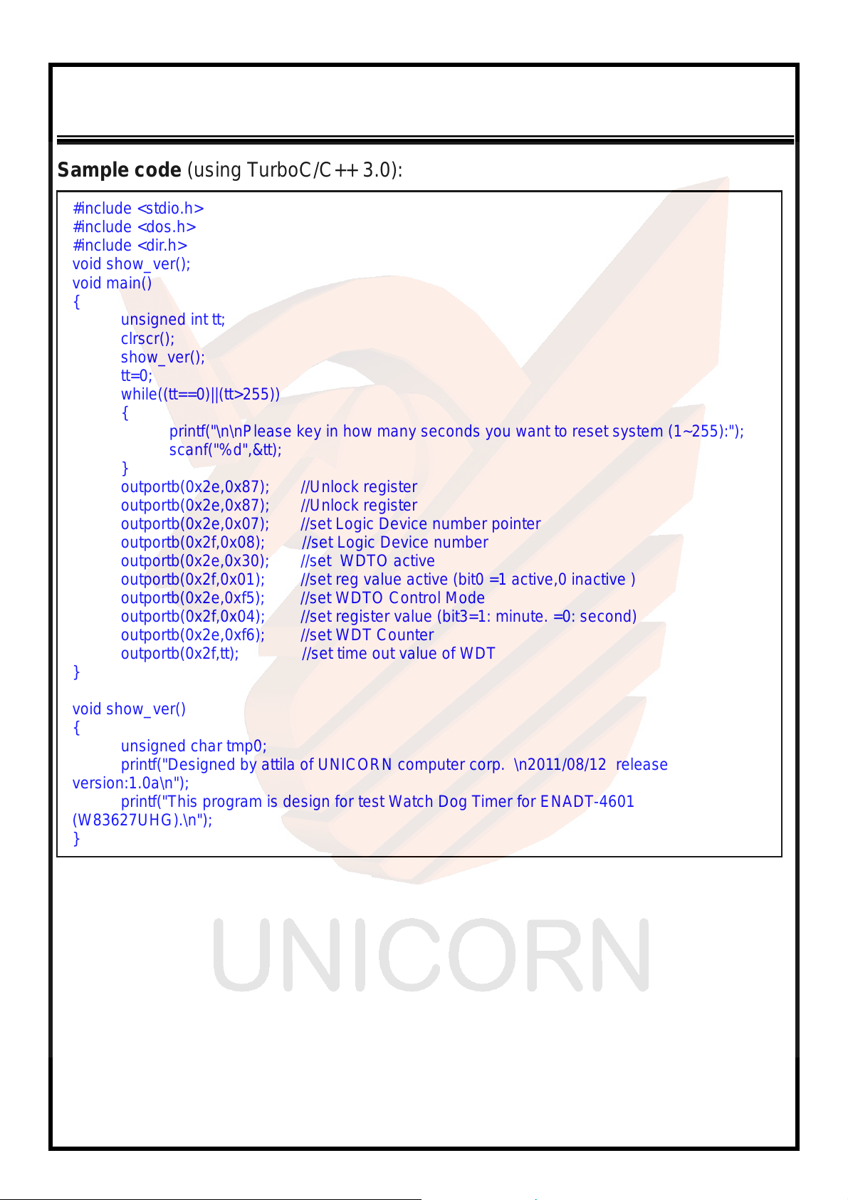
2-4. Watch Dog Timer
Watch dog Timer (WDT) is designed to monitor and secure the system work
normally. WDT has an independent clock from the oscillator that can set time and
clear/refresh WDT counter function . When time is up, WDT send hardware RESET
signal to reset system.
Timeout Value Range
-1 to 255
-Second or Minute
14
Page 15
ENDAT-4601 USERS MANUAL
UNICORN COMPUT ER CORP.
Sample code (using TurboC/C++ 3.0):
#include <stdio.h>
#include <dos.h>
#include <dir.h>
void show_ver();
void main()
{
unsigned int tt;
clrscr();
show_ver();
tt=0;
while((tt==0)||(tt>255))
{
printf("\n\nPlease key in how many seconds you want to reset system (1~255):");
scanf("%d",&tt);
}
outportb(0x2e,0x87); //Unlock register
outportb(0x2e,0x87); //Unlock register
outportb(0x2e,0x07); //set Logic Device number pointer
outportb(0x2f,0x08); //set Logic Device number
outportb(0x2e,0x30); //set WDTO active
outportb(0x2f,0x01); //set reg value active (bit0 =1 active,0 inactive )
outportb(0x2e,0xf5); //set WDTO Control Mode
outportb(0x2f,0x04); //set register value (bit3=1: minute. =0: second)
outportb(0x2e,0xf6); //set WDT Counter
outportb(0x2f,tt); //set time out value of WDT
}
void show_ver()
{
unsigned char tmp0;
printf("Designed by attila of UNICORN computer corp. \n2011/08/12 release
version:1.0a\n");
printf("This program is design for test Watch Dog T imer for ENADT-4601
(W83627UHG).\n");
}
15
Page 16
ENDAT-4601 USERS MANUAL
UNICORN COMPUTER CORP.
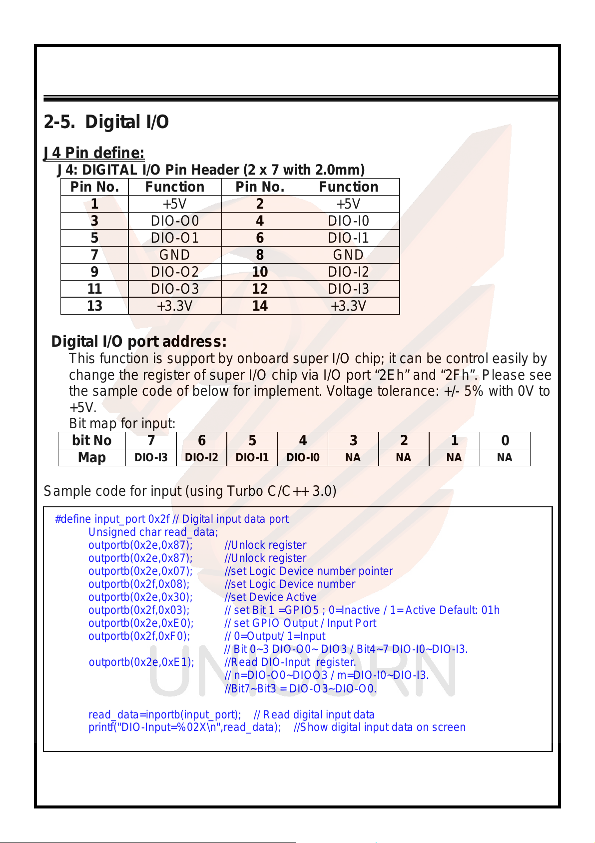
2-5. Digital I/O
J4 Pin define:
J4: DIGITAL I/O Pin Header (2 x 7 with 2.0mm)
Pin No. Function Pin No. Function
1 +5V 2 +5V
3 DIO-O0 4 DIO-I0
5 DIO-O1 6 DIO-I1
7 GND 8 GND
9 DIO-O2 10 DIO-I2
11 DIO-O3 12 DIO-I3
13 +3.3V 14 +3.3V
Digital I/O port address:
This function is support by onboard super I/O chip; it can be control easily by
change the register of super I/O chip via I/O port “2Eh” and “2Fh”. Please see
the sample code of below for implement. Voltage tolerance: +/- 5% with 0V to
+5V.
Bit map for input:
bit No 7 6 5 4 3 2 1 0
Map
Sample code for input (using Turbo C/C++ 3.0)
#define input_port 0x2f // Digital input data port
outportb(0x2e,0x87); //Unlock register
outportb(0x2e,0x87); //Unlock register
outportb(0x2e,0x07); //set Logic Device number pointer
outportb(0x2f,0x08); //set Logic Device number
outportb(0x2e,0x30); //set Device Active
outportb(0x2f,0x03); // set Bit 1 =GPIO5 ; 0=Inactive / 1= Active Default: 01h
outportb(0x2e,0xE0); // set GPIO Output / Input Port
outportb(0x2f,0xF0); // 0=Output/ 1=Input
// Bit 0~3 DIO-O0~ DIO3 / Bit4~7 DIO-I0~DIO-I3.
outportb(0x2e,0xE1); //Read DIO-Input register.
Unsigned char read_data;
//Bit7~Bit3 = DIO-O3~DIO-O0.
read_data=inportb(input_port); // Read digital input data
printf("DIO-Input=%02X\n",read_data); //Show digital input data on screen
DIO-I3 DIO-I2 DIO-I1 DIO-I0 NA NA NA NA
// n=DIO-O0~DIOO3 / m=DIO-I0~DIO-I3.
16
Page 17
ENDAT-4601 USERS MANUAL
UNICORN COMPUT ER CORP.
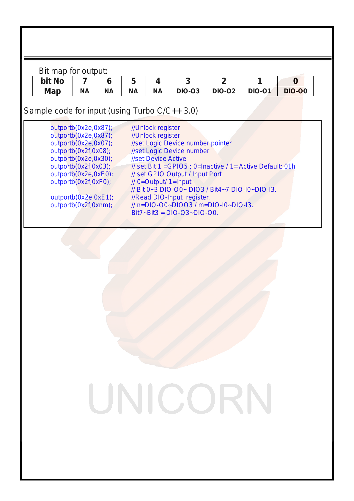
Bit map for output:
bit No 7 6 5 4 3 2 1 0
Map
Sample code for input (using Turbo C/C++ 3.0)
outportb(0x2e,0x87); //Unlock register
outportb(0x2e,0x87); //Unlock register
outportb(0x2e,0x07); //set Logic Device number pointer
outportb(0x2f,0x08); //set Logic Device number
outportb(0x2e,0x30); //set Device Active
outportb(0x2f,0x03); // set Bit 1 =GPIO5 ; 0=Inactive / 1= Active Default: 01h
outportb(0x2e,0xE0); // set GPIO Output / Input Port
outportb(0x2f,0xF0); // 0=Output/ 1=Input
// Bit 0~3 DIO-O0~ DIO3 / Bit4~7 DIO-I0~DIO-I3.
outportb(0x2e,0xE1); //Read DIO-Input register.
outportb(0x2f,0xnm); // n=DIO-O0~DIOO3 / m=DIO-I0~DIO-I3.
Bit7~Bit3 = DIO-O3~DIO-O0.
NA NA NA NA DIO-O3 DIO-O2 DIO-O1 DIO-O0
17
Page 18
ENDAT-4601 USERS MANUAL
UNICORN COMPUTER CORP.
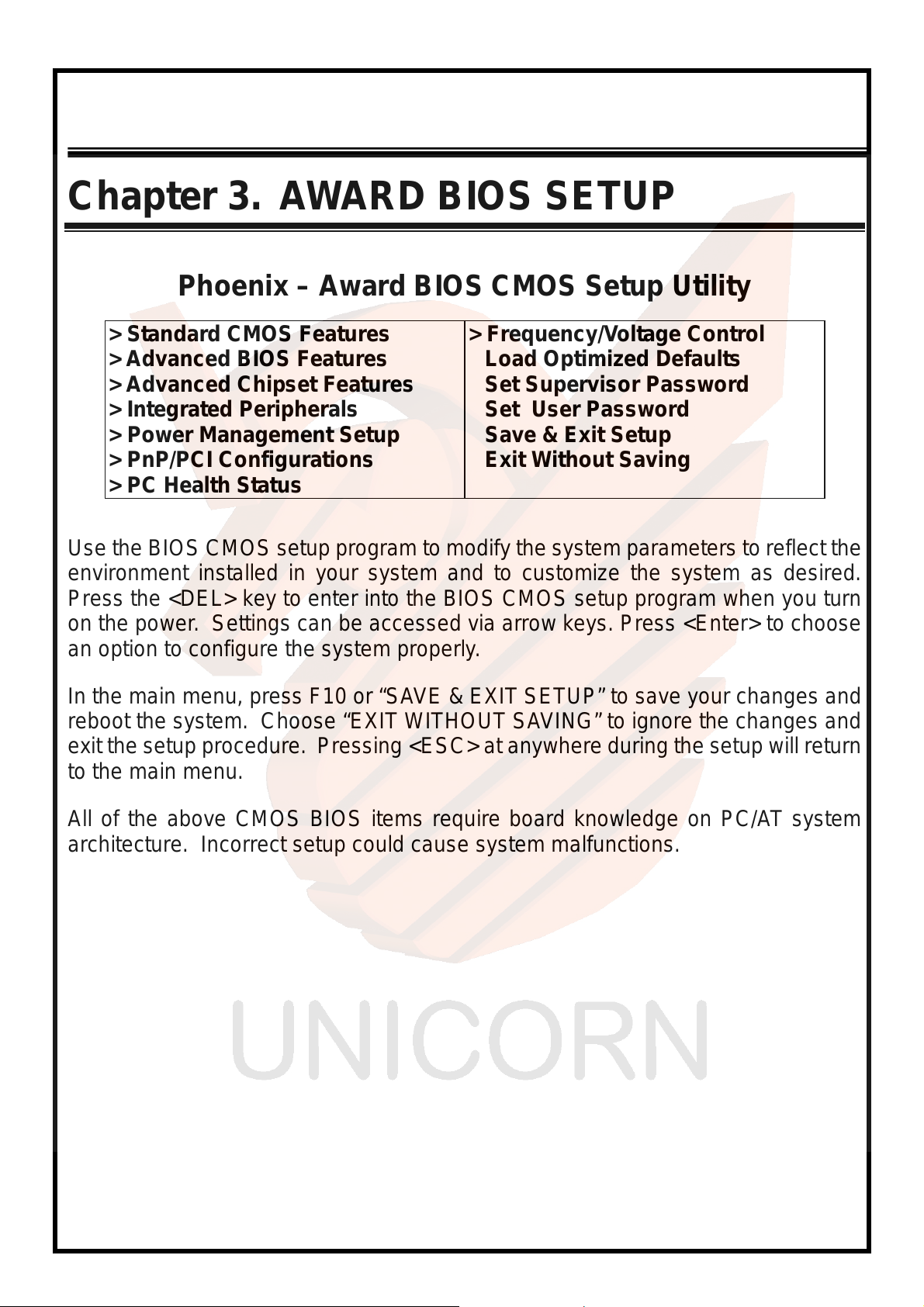
Chapter 3. AWARD BIOS SETUP
Phoenix – Award BIOS CMOS Setup Utility
> Standard CMOS Features
> Advanced BIOS Features
> Advanced Chipset Features
> Integrated Peripherals
> Power Management Setup
> PnP/PCI Configurations
> PC Health Status
Use the BIOS CMOS s etup progra m to modify the system p arameters to reflect the
environment installed in your system and to customize the system as desired.
Press the <DEL> key to enter into the BI OS CMOS set up pro gram when yo u tur n
on the power. Settings can be accessed via arrow keys. Press <Enter> to choose
an option to configure the system properly.
In the main menu, press F10 or “SAVE & EXIT SETUP” to save your changes and
reboot the system. Choose “EXIT WITHOUT SAVING” to ignore the changes and
exit the setup procedure. Press ing <ESC> at anywhere during the setup will return
to the main menu.
> Frequency/Voltage Control
Load Optimized Defaults
Set Supervisor Password
Set User Password
Save & Exit Setup
Exit Without Saving
All of the above CMOS BIOS items require board knowledge on PC/AT system
architecture. Incor rect setup could cause system malfunctions.
18
Page 19
ENDAT-4601 USERS MANUAL
UNICORN COMPUT ER CORP.
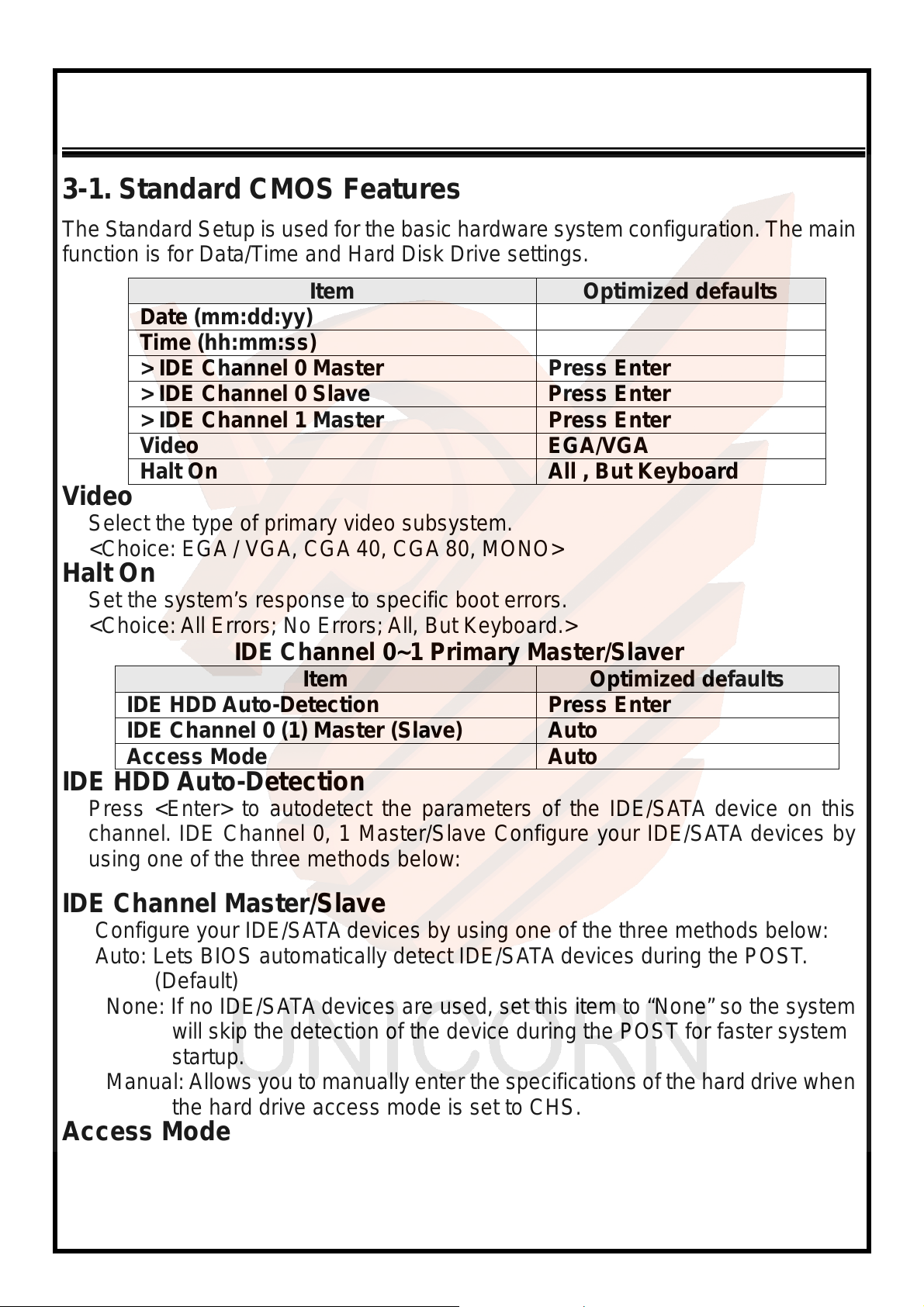
3-1. Standard CMOS Features
The S tandard Setup is used for the basic hardware system configuration. The main
function is for Data/Time and Hard Disk Drive settings.
Item Optimized defaults
Date (mm:dd:yy)
Time (hh:mm:ss)
> IDE Channel 0 Master Press Enter
> IDE Channel 0 Slave Press Enter
> IDE Channel 1 Master Press Enter
Video EGA/VGA
Halt On All , But Keyboard
Video
Select the type of primary video subsystem.
<Choice: EGA / VGA, CGA 40, CGA 80, MONO>
Halt On
Set the system’s response to specific boot errors.
<Choice: All Errors; No Errors; All, But Keyboard.>
IDE Channel 0~1 Primary Master/Slaver
Item Optimized defaults
IDE HDD Auto-Detection Press Enter
IDE Channel 0 (1) Master (Slave) Auto
Access Mode Auto
IDE HDD Auto-Detection
Press <Enter> to autodetect the parameters of the IDE/SATA device on this
channel. IDE Channel 0, 1 Master/Slave Configur e your IDE/SATA devi ces by
using one of the three methods below:
IDE Channel Master/Slave
Configure your IDE/SATA devices by using one of the thre e methods below:
Auto: Lets BIOS automatically detect IDE/SATA devices during the POST.
(Default)
None: If no IDE/SATA devices are used, set this item to “None” so the system
will skip the detectio n of the device during the POST for faster system
startup.
Manual: Allows you to manually enter the specifications of the hard drive when
the hard drive access mode is set to CHS.
Access Mode
Set the hard drive access m ode. Options are: Auto (de fault), CHS, LBA,
and Large.
19
Page 20
ENDAT-4601 USERS MANUAL
UNICORN COMPUTER CORP.
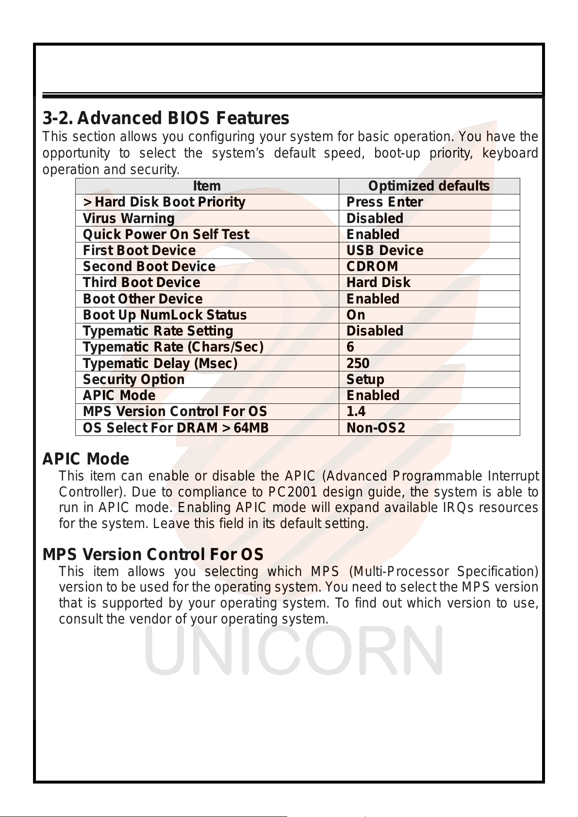
3-2. Advanced BIOS Features
This section allows you conf iguring yo ur syste m for basic ope ration. You have the
opportunity to select the system’s default speed, boot-up priority, keyboard
operation and se cu r it y.
Item Optimized defaults
> Hard Disk Boot Priority Press Enter
Virus Warning Disabled
Quick Power On Self Test Enabled
First Boot Device USB Device
Second Boot Device CDROM
Third Boot Device Hard Disk
Boot Other Device Enabled
Boot Up NumLock Status On
Typematic Rate Setting Disabled
Typematic Rate (Chars/Sec) 6
Typematic Delay (Msec) 250
Security Option Setup
APIC Mode Enabled
MPS Version Control For OS 1.4
OS Select For DRAM > 64MB Non-OS2
APIC Mode
This item can enable or disable the APIC (Advanced Programmable Interrupt
Controller). Due to compliance to PC2001 design guide, the system is able to
run in APIC mode. Enabling APIC mode will expand available IRQs resources
for the system. Leave this field in its default setting.
MPS Version Control For OS
This item allows you selecting which MPS (Multi-Processor Specification)
version to be used for the operating system. Y ou need to select the MPS version
that is supported by your operating system. To find out which version to use,
consult the vendor of your operating system.
20
Page 21
ENDAT-4601 USERS MANUAL
UNICORN COMPUT ER CORP.
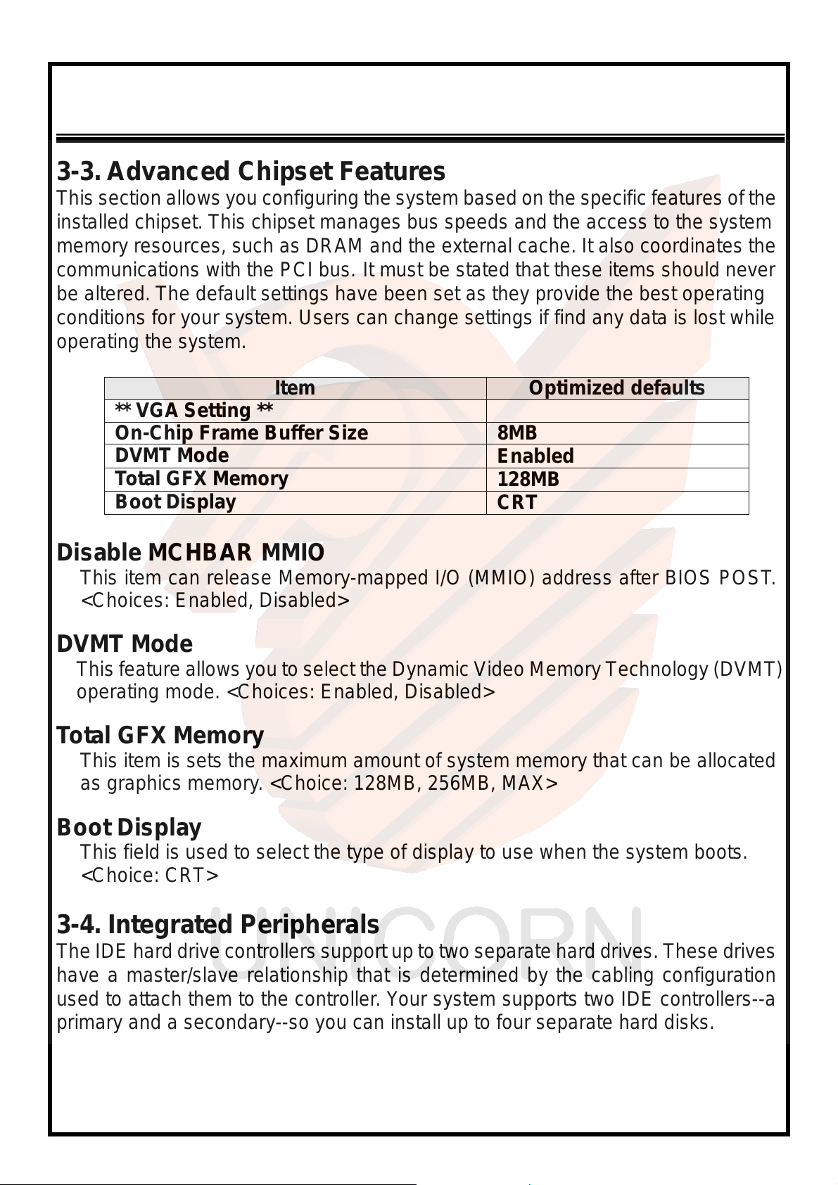
3-3. Advanced Chipset Features
This section allows you configuring the system based on the specific features of the
installed chipset. This chipset manages bus speeds and the access to the system
memory resources, such as DRAM and the external cache. It also coordinates the
communications with the PCI bus.
be altered. The default settings have been set as they provide the best operating
conditions for your syst em. Users can change settings if find any data is lost while
operating the system.
Item Optimized def a ul ts
** VGA Setting **
On-Chip Frame Buffer Size 8MB
DVMT Mode
Total GFX Memory
Boot Display
It must be stated that these items should never
Enabled
128MB
CRT
Disable MCHBAR MMIO
This item can release Memory-mapped I/O (MMIO) address after BIOS POST.
<Choices: Enabled, Disabled>
DVMT Mode
This feature allows you to s elect the Dynamic Video Memory Technology (DVMT)
operating mode. <Choices: Enabled, Disabled>
Total GFX Memory
This item is sets the maximum amount of system memory that can be allocated
as graphics memory. <Choice: 128MB, 256MB, MAX>
Boot Display
This field is used to select the type of display to use when the system boots.
<Choice: CRT>
3-4. Integrated Peripherals
The IDE hard drive controllers support up to two separate hard drives. These drives
have a master/slave relationship that is determined by the cabling configuration
used to attach them to the c ontroll er. Your system supports two I DE controlle rs--a
primary and a secondary--so you can install up to four separate hard disks.
21
Page 22
ENDAT-4601 USERS MANUAL
UNICORN COMPUTER CORP.
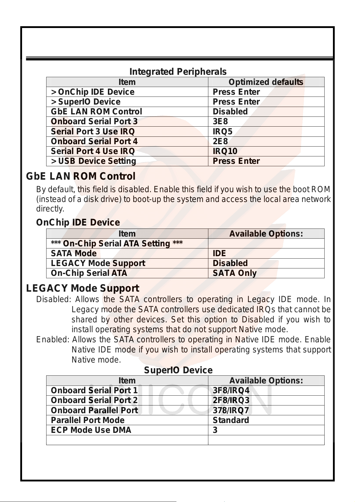
Integrated Peripherals
Item Optimized defaults
> OnChip IDE Device Press Enter
> SuperIO Device Press Enter
GbE LAN ROM Control Disabled
Onboard Serial Port 3 3E8
Serial Port 3 Use IRQ IRQ5
Onboard Serial Port 4 2E8
Serial Port 4 Use IRQ IRQ10
> USB Device Setting Press Enter
GbE LAN ROM Control
By default, this field is disabled. Enable this field if you wish to use the boot ROM
(instead of a disk drive) to boot-up the system and access the local area network
directly.
OnChip IDE Device
Item Available Options:
*** On-Chip Serial ATA Setting ***
SATA Mode IDE
LEGACY Mode Support Disabled
On-Chip Serial ATA SATA Only
LEGACY Mode Support
Disabled: Allows the SATA controllers to operating in Legacy IDE mode. In
Legacy mode the SATA controllers use dedicated IRQs that cannot be
shared by other devices. Set this option to Disabled if you wish to
install operating systems that do not support Native mode.
Enabled: Allows the SATA controllers to operating in Native IDE mode. Enable
Native IDE mode if you wish to install operating systems that support
Native mode.
SuperIO Device
Item Available Options:
Onboard Serial Port 1 3F8/IRQ4
Onboard Serial Port 2 2F8/IRQ3
Onboard Parallel Port 378/IRQ7
Parallel Port Mode Standard
ECP Mode Use DMA 3
PWRON After PWR-Fail off
22
Page 23
ENDAT-4601 USERS MANUAL
UNICORN COMPUT ER CORP.
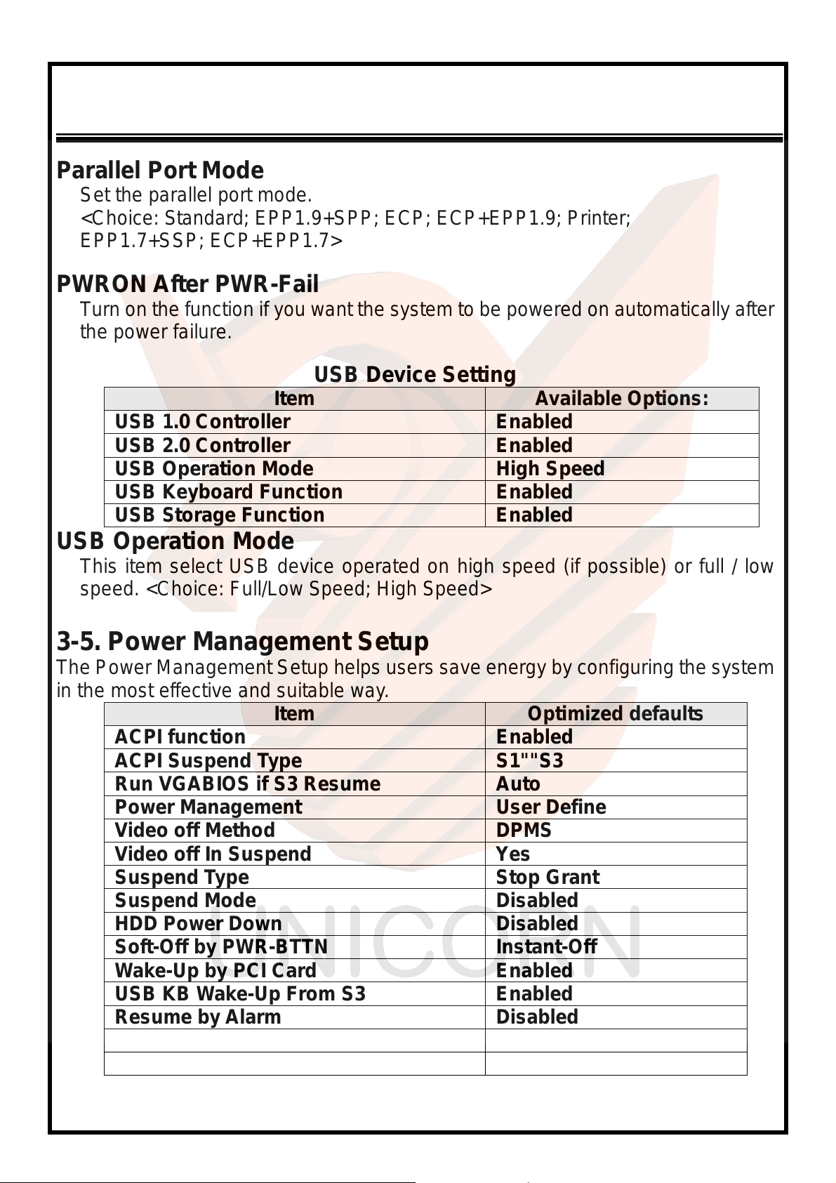
Parallel Port Mode
Set the parallel port mode.
<Choice: Standard; EPP1.9+SPP; ECP; ECP+EPP1.9; Printer;
EPP1.7+SSP; ECP+EPP1.7>
PWRON After PWR-Fail
Turn on the function if you want the system to be powered on automatically after
the power failure.
USB Device Setting
Item Available Options:
USB 1.0 Controller Enabled
USB 2.0 Controller Enabled
USB Operation Mode High Speed
USB Keyboard Function Enabled
USB Storage Function Enabled
USB Operation Mode
This item select USB device operated on high speed (if possible) or full / low
speed. <Choice: Full/Low Speed; High Speed>
3-5. Power Management Setup
The Power Management Setup helps users save energy by configuring the system
in the most effective and suitable way.
Item Optimized def a ul ts
ACPI function Enabled
ACPI Suspend Type S1""S3
Run VGABIOS if S3 Resume Auto
Power Management User Define
Video off Method DPMS
Video off In Suspend Yes
Suspend Type Stop Grant
Suspend Mode Disabled
HDD Power Down Disabled
Soft-Off by PWR-BTTN Instant-Off
Wake-Up by PCI Card Enabled
USB KB Wake-Up From S3 Enabled
Resume by Alarm Disabled
Date (of Month) Alarm 0
Time (hh:mm:ss) Alarm 0 : 0 : 0
23
Page 24
ENDAT-4601 USERS MANUAL
UNICORN COMPUTER CORP.
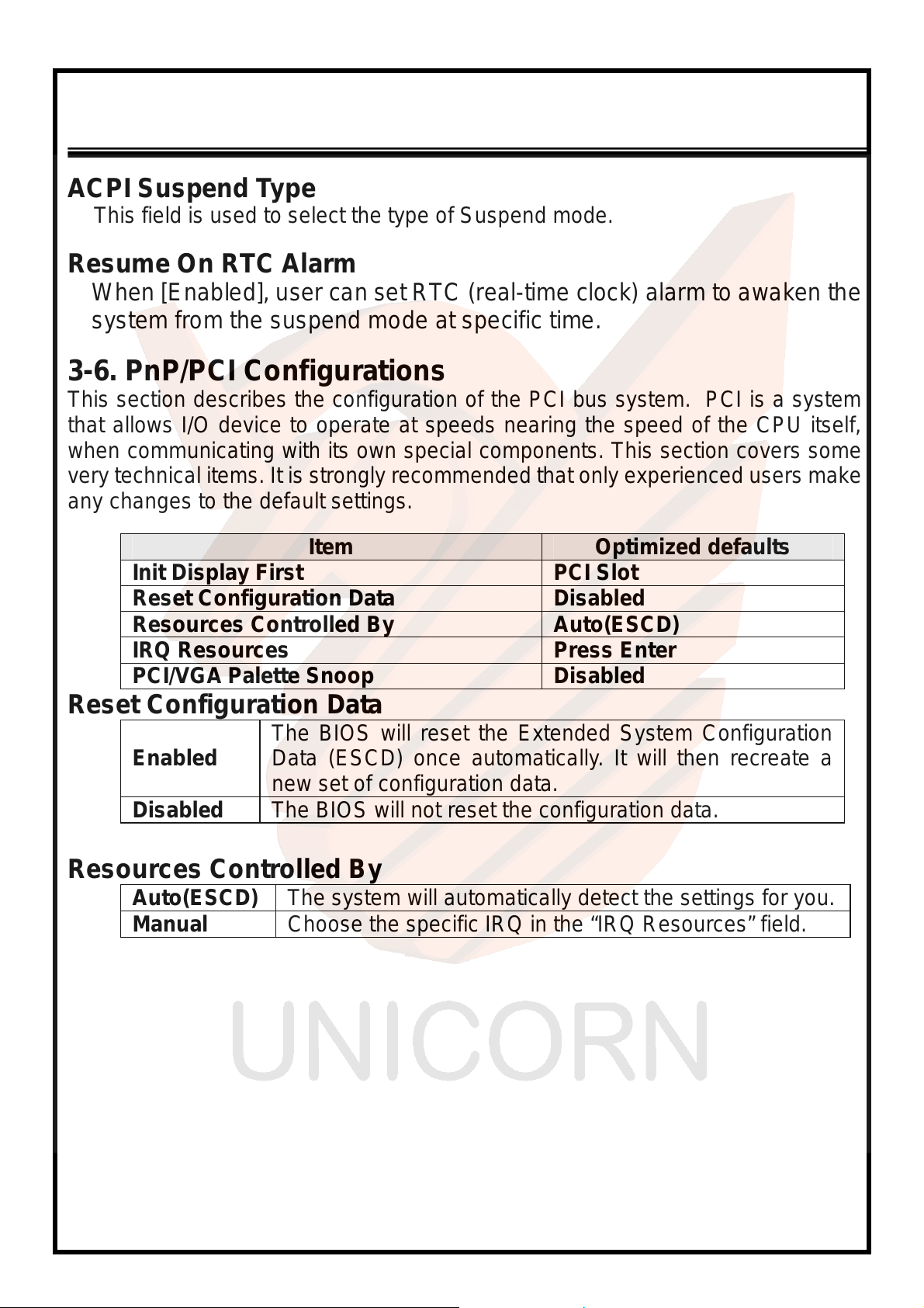
ACPI Suspend Type
This field is used to select the type of Suspend mode.
Resume On RTC Alarm
When [Enabled], user can set RTC (real-time clock) alarm to awaken the
system from the suspend mode at specific time.
3-6. PnP/PCI Configurations
This section describe s the configuration of the PCI bus system. PCI is a system
that allows I/O devi ce to operate at speeds nearing the speed of the CPU itself,
when communicating with its own special components. This section covers some
very technical items. It is strongly recommended that only experienced users make
any changes to the default set tings.
Item Optimized defaults
Init Display First PCI Slot
Reset Configuration Data Disabled
Resources Controlled By Auto(ESCD)
IRQ Resources Press Enter
PCI/VGA Palette Snoop Disabled
Reset Configuration Data
The BIOS will reset the Extended System Configuration
Enabled
Disabled The BIOS will not reset the configuration data.
Data (ESCD) once automatically. It will then recreate a
new set of configuration data.
Resources Controlled By
Auto(ESCD) The system will automatically detect the settings for you.
Manual Choose the specific IRQ in the “IRQ Resources” field.
24
Page 25
ENDAT-4601 USERS MANUAL
UNICORN COMPUT ER CORP.
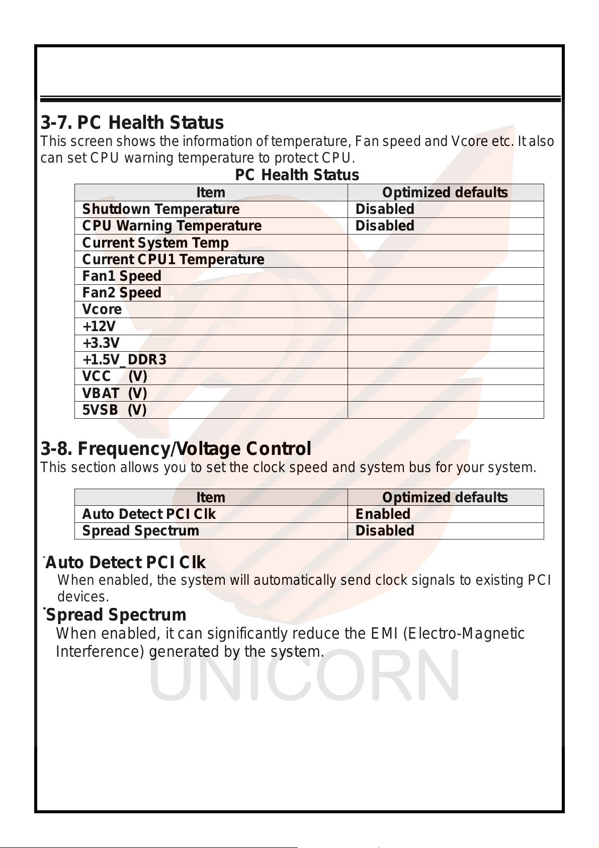
3-7. PC Health Status
This screen show s the information of temperature, Fan speed and Vcore etc. It also
can set CPU warning temperature to protect CPU.
PC Health Status
Item Optimized defaults
Shutdown Temperature Disabled
CPU Warning Temperature Disabled
Current System Temp
Current CPU1 Temperat ure
Fan1 Speed
Fan2 Speed
Vcore
+12V
+3.3V
+1.5V_DDR3
VCC (V)
VBAT (V)
5VSB (V)
3-8. Frequency/Voltage Control
This section allows you to set the clock speed and system bus for your system.
Item Optimized defaults
Auto Detect PCI Clk Enabled
Spread Spectrum Disabled
˙Auto Detect PCI Clk
When enabled, the system will automatically send clock signals to existing PCI
devices.
˙Spread Spectrum
When enabled, it can significantly reduce the EMI (Electro-Magnetic
Interference) generated by the system.
25
Page 26
ENDAT-4601 USERS MANUAL
UNICORN COMPUTER CORP.
Chapter 4. VGA, SDVO and drivers
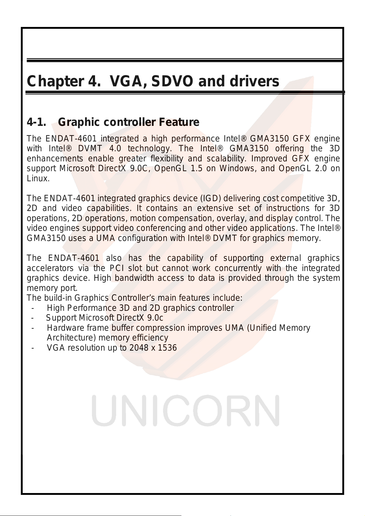
4-1. Graphic controller Feature
The ENDAT-4601 integrated a high performance Intel® GMA3150 GFX engine
with Intel® DVMT 4.0 technology. The Intel® GMA3150 offering the 3D
enhancements enable greater flexibility and scalability. Improved GFX engine
support Microsoft DirectX 9.0C, OpenGL 1.5 on Windows, and OpenGL 2.0 on
Linux.
The ENDAT-4601 integrated graphics device (IGD) delivering cost competitive 3D,
2D and video capabilities. It contains an extensive set of instructions for 3D
operations, 2D operations, motion compensation, overlay, and display control. The
video engines support video conferencing and other video applications. The Intel®
GMA3150 uses a UMA configuration with Intel® DVMT for graphics memory.
The ENDAT-4601 also has the capability of supporting external graphics
accelerators via the PCI slot but cannot work concurrently with the integrated
graphics device. High bandwidth access to data is provided through the system
memory port.
The build-in Graphics Controller’s main features include:
- High Performance 3D and 2D graphics controller
- Support Microsoft DirectX 9.0c
- Hardware frame buffer compression improves UMA (Unified Memory
Architecture) memory efficiency
- VGA resolution up to 2048 x 1536
26
Page 27

ENDAT-4601 USERS MANUAL
UNICORN COMPUT ER CORP.
4-2. Driver Utility Installation Guide
1.
2. Please cont act sal es depart ment of UNICORN for Embedded OS user driver
Please download or check from
information or last versions of driver as needs!
When finishing the installation of Windows XP, Vista, please install the relative
chipsets, display and AUDIO driver manually for compliance compatibility of hardware
environment.
(Linux, Windows CE and Windows XP embedded). All of embedded OS driver
is not be included in any versions of driver CD-ROM from UNICORN.
Intel®
web site:
www.intel.com
for more
Intel®
27
Page 28
ENDAT-4601 USERS MANUAL
UNICORN COMPUTER CORP.
Appendix A: FLASH MEMOR Y UTILITY
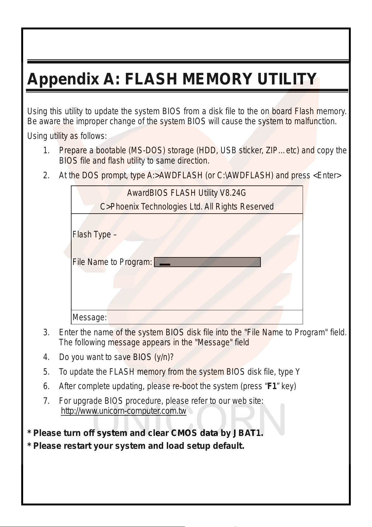
Using this utility to update the system BIOS from a disk file to the on board Flash memory.
Be aware the improper change of the system BIOS will cause the system to malfunction.
Using utility as follows:
1. Prepare a bootable (MS-DOS) storage (HDD, USB sticker, ZIP…etc) and copy the
BIOS file and flash utility to same direction.
2. At the DOS prompt, type A:>AWDFLASH (or C:\AWDFLASH) and press <Enter>
AwardBIOS FLASH Utility V8.24G
C>Phoenix Technologies Ltd. All Rights Reserved
Flash T ype –
File Name to Program:
Message:
3. Enter the name of the system BIOS disk file into the "File Name to Program" field.
The following message appears in the "Message" field
4. Do you want to save BIOS (y/n)?
5. To update the FLASH memory from the system BIOS disk file, type Y
6. After complete updating, please re-boot the system (press “
7.
For upgrade BIOS procedure, please refer to our web site:
http://www .unicorn-computer.com.tw
F1
” key)
* Please turn off system and clear CMOS data by JBAT1.
* Please restart your system and load setup default.
28
Page 29

ENDAT-4601 USERS MANUAL
UNICORN COMPUT ER CORP.
Appendix B: LIMITED WARRANTY
Standard Two years limited warranty on all our ENDAT series all-in-one
motherboards and embedded board. Products that become defective during the
warranty period shall be repaired, or subject to manufacturer’s option, replaced.
The limited warranty applies to normal proper usage of the hardware and does not
cover products that have been modified or subjected to unusual electrical or
physical stress. Unicorn Computer Corp is not liable to repair or replace defective
goods caused by improper using or use of unauthorized parts. The following
situations will be ch arged:
1. The products during the warranty but defective caused by improper using or
artificial extern al p ressure and resul t in the comp onent s da mages. According to
the damage situation, the manufacturer has the rights to decide to repair or not.
The manufacturer will charge the parts/repair cost and the returning shipping
charge.
2. The produ cts out of warranty wil l charge the parts /repair co st and the r eturni ng
shipping charge as per the repair status.
3. The manufacturer has the rights to decide to repair or not based on the stock of
parts for the products which are phased out of the pr oduction.
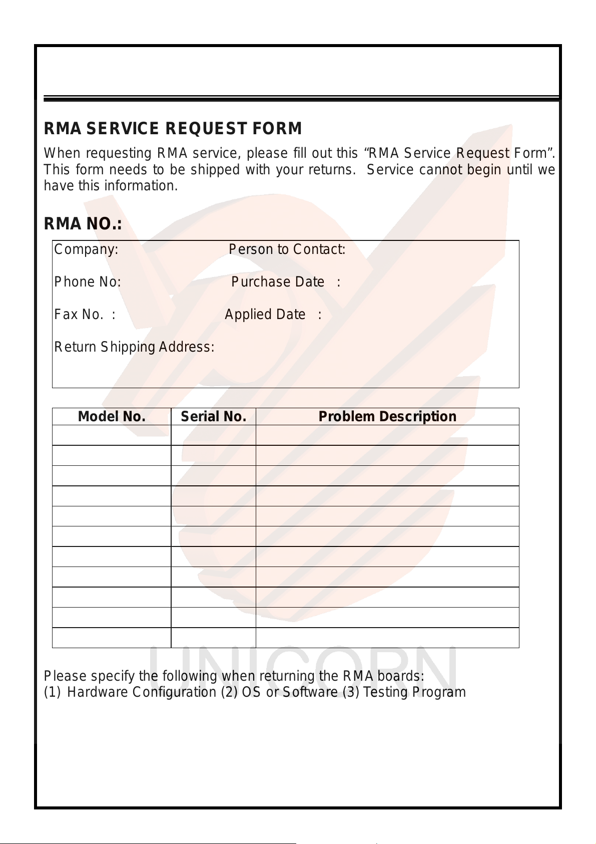
4. Please e-mail or fax the RMA Service Request Form when have the defective
products.
29
Page 30
ENDAT-4601 USERS MANUAL
UNICORN COMPUTER CORP.
RMA SERVICE REQUEST FORM
When requesting RMA service, please fill out this “RMA Service Request Form”.
This form needs to be shipped with your returns. Service cannot begin until we
have this information.
RMA NO.:
Company: Person to Contact:
Phone No: Purchase Date :
Fax No. : Applied Date :
Return Shipping Address:
Model No. Serial No. Problem Description
Please specify the following when returning the RMA boards:
(1) Hardware Configuration (2) OS or Software (3) Testing Program
___________________
Authorized Signature
30
 Loading...